ABB RMIO-12C is a widely used control unit in the field of industrial automation, with many advantages such as high performance and high reliability.
Basic information
Belonging to the RMIO series, brand ABB, model RMIO-12C, weighing 0.6kg, module size 150 × 100 × 80mm, certified by CE, UL, CSA, etc., in compliance with industry quality standards.
Performance parameters
The working voltage is 120V AC or 24V DC (some data shows 220V), the working frequency is 50kHz, and the output frequency is also 50kHz. It can provide precise control for equipment that requires high response speed and control accuracy, such as high-speed motors. Supports communication protocols such as Modbus RTU/TCP for easy communication with other devices that support this protocol, enabling system integration and remote monitoring. There are 16 input channels and 16 output channels, which can connect various sensors and actuators to meet the control needs of different industrial scenarios.
Functional features
Adopting advanced microprocessor technology, built-in multiple control algorithms, customizable programming, able to design control strategies according to different industrial needs, such as controlling the operation process and parameters of equipment in industrial automation production lines. Supporting remote control and monitoring, with the help of communication interfaces, operators can remotely operate and monitor the status of equipment, improving the convenience and efficiency of production management. Equipped with comprehensive safety protection functions, it can monitor the operating status of equipment, and take timely protective measures in case of abnormalities such as overload and short circuit to ensure the safety of equipment and personnel. Equipped with a software library that includes rich pre-defined and user-defined control elements, it is easy to design various control strategies, covering continuous control, timing control, etc., to adapt to complex industrial control requirements.
Application areas
Widely used in industrial automation production lines, controlling the operation of various equipment, improving production efficiency and product quality; In robot control systems, precise control of robots is achieved to enable them to complete complex tasks; In industries such as manufacturing, energy, and process control, control and monitor equipment such as motors, generators, and transformers to ensure stable system operation.
Related configuration
As part of the control unit in ABB ACS800 frequency converter, it works in conjunction with rectifier unit, energy storage unit, inverter unit, etc. to achieve drive control of the motor and stable operation of the entire system. It can seamlessly integrate with various ABB products, build comprehensive automation solutions, and enhance the overall performance and compatibility of the system.
Connector type and parameters
There are various types of connectors, such as X20 (constant voltage output) with 2-pole detachable screw terminal blocks, etc. Different connectors are suitable for different wire specifications, torques, spacing, etc.
Constant voltage output (X20, X21:1): Voltage of+10 VDC, 0, -10 VDC ± 0.5% (full-scale range) (at 25 ° C), maximum temperature coefficient of ± 100 ppm/° C, maximum load of 10mA, suitable for potentiometers 1 to 10 kohm.
Analog inputs (X21): Two programmable differential current inputs and one programmable differential voltage input, with analog inputs grouped together for galvanic isolation, etc.
Analog output (X21): Two programmable current outputs with a resolution of 0.1% (10 bits), etc.
Digital input (X22): Six programmable digital inputs and one startup interlock input, internal digital input power supply (+24 VDC) with short-circuit protection, etc.
24 VDC power output (X23): Voltage 24 VDC ± 10%, with short-circuit protection, maximum output current 250 mA (when no optional module is inserted).
Relay outputs (X25, X26, X27): Three programmable relay outputs with corresponding specifications for switch capacity.
Slot 1 (X31), Slot 2 (X32): Used for connecting related expansion modules, etc.
DDCS (X33): Used to connect RDCO-0x (C) DDCS communication module.
24 VDC power input (X34): Voltage 24 VDC ± 10%, typical current consumption (without option module) 250 mA, maximum current consumption 1200 mA (with option module inserted), etc.
Control panel connection (X39): used to connect the CDP-312R control panel.
PPCS link (V57, V68): Fiber optic connection to inverter (or IGBT power supply) module, optical component type 10 MBd, protocol ABB PPCS.
The ABB XO08R1-B4.0 extended output module is a key component used in the field of industrial automation to expand the input/output (I/O) capabilities of ABB PLC, which can endow automation control systems with more powerful functions. It demonstrates extremely high reliability and stability with advanced technological architecture, and can operate continuously and stably for a long time, providing solid support for automation control requirements in complex industrial environments.
Core functions
I/O channel expansion: This module provides multiple additional output channels for ABB PLC, specifically with 8 digital output channels, greatly expanding the system’s output control points. Through these new channels, it is possible to connect and control more external loads, such as relays, contactors, indicator lights, solenoid valves, and other actuating components, to meet the diverse needs of automation control scenarios. For example, on an automated production line, it may be necessary to control numerous device actions, and the XO08R1-B4.0 module can help PLC easily achieve precise control of more devices.
Signal conversion and amplification: It can convert and amplify the digital signals output by PLC. The signals output by PLC are usually of low power, making it difficult to directly drive some high-power loads. And this expansion module can convert digital signals into output signals with sufficient driving capability to adapt to the working requirements of different loads. For example, it can convert the low-level digital signals output by the PLC into high voltage and high current signals that can drive the contactor coils, ensuring reliable contactor engagement and controlling high-power equipment such as motors.
Protocol communication support: Standard Modbus RTU communication protocol is used for communication. This protocol is widely used in the industrial field, with strong universality and good compatibility. Through this protocol, the XO08R1-B4.0 module can efficiently and stably exchange data with PLCs and other devices that support Modbus RTU protocol. Whether working with a single PLC in a small automation system or collaborating with numerous devices in a large complex industrial network, seamless integration can be achieved through this communication protocol, ensuring the accuracy and timeliness of data transmission.
Technical parameters
Output type: The output type is relay output, and the relay contacts support normally open or normally closed contact forms. This output method has the advantages of good isolation performance and strong load capacity, which can effectively isolate the control circuit from the load circuit, avoid mutual interference, and can withstand large currents and voltages. It is suitable for various types of load control.
Output current: Each channel can carry a maximum current of 2A, which can meet the driving requirements of common industrial loads. Whether it’s small indicator lights, buzzers, or slightly high-power relays, solenoid valves, and other devices, they can all work stably within their driving capabilities.
Rated voltage: The rated working voltage is 24V DC, which is a commonly used DC voltage level in industrial automation control systems. It matches the power supply voltage of most PLCs and other industrial equipment, making it easy to configure and connect power in the system.
Power consumption: The power consumption of the module during normal operation is about 5W, which is relatively low. While ensuring efficient operation, it helps to reduce the energy consumption of the entire system and improve energy utilization efficiency.
Protection level: The protection level reaches IP20 (IEC529). This protection level can prevent solid foreign objects larger than 12mm from entering, such as fingers, and also prevent vertical water droplets from affecting the module. It is suitable for general indoor industrial environments. When installed and used in some relatively clean and dry control cabinets, it can effectively protect the internal circuit of the module from external foreign objects and water droplets, ensuring stable operation.
Working temperature range: The working temperature range is -25 ° C to+55 ° C, with a wide temperature adaptability. This enables the module to operate normally in different industrial environment temperatures, whether in factories in cold regions or workshops in hot environments, providing possibilities for the application of industrial automation systems in different regions and working conditions.
Installation and maintenance
Installation method: Supports two common methods: panel installation or DIN rail installation. Panel installation is suitable for situations where there are specific requirements for the installation position and the module needs to be fixed on the control cabinet panel or other positions for easy observation and operation; DIN rail installation is simple and fast to operate. Simply insert the module into the standard DIN rail, which saves space, facilitates centralized installation and layout in the electrical control cabinet, and makes it easy for technicians to install and maintain the equipment.
Maintenance points: During daily maintenance, it is necessary to regularly check the working status of the module. By using the indicator lights on the module, the working status of each output channel can be intuitively judged. If the indicator lights are on or off normally, it indicates that the corresponding channel is working properly; If the indicator light is abnormal, such as not on or constantly on, it may indicate a fault in the channel. In addition, it is necessary to regularly check whether the wiring terminals are loose, ensure that the electrical connections are firm and reliable, and prevent problems such as heating and ignition caused by poor contact, which may affect the normal operation of the module and the entire system. When a module malfunction is detected, its modular design facilitates quick replacement of faulty modules, reduces downtime, and minimizes the impact on production.
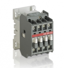
ABB 5SGX1060H0003 AC contactor, as a key equipment in the field of industrial electrical control, plays an important role in control and protection in many electrical systems. It can frequently connect and disconnect AC circuits, effectively control various AC loads, and is widely used in many fields such as manufacturing, energy industry, transportation, etc. that require extremely high electrical control reliability. With the profound foundation of ABB brand in the fields of power and automation technology, this AC contactor integrates advanced design concepts and exquisite manufacturing processes, providing solid guarantees for efficient and stable operation of industrial production.
Core functions
Circuit on-off control: This is the core function of AC contactors. When the electromagnetic coil is powered on, it generates a magnetic field that attracts the moving iron core, drives the contact to move, closes the main contact, and connects the circuit, thereby achieving power supply to the AC load; When the electromagnetic coil is powered off, the magnetic field disappears, and the moving iron core returns to its original position under the action of the reset spring, causing the main contact to disconnect and cutting off the circuit. Through this method, it is possible to efficiently and accurately control the on/off of AC circuits to meet the operational needs of different devices.
Undervoltage and Loss of Voltage Protection: Equipped with undervoltage and loss of voltage protection functions. When the circuit voltage drops to a certain level (usually below 70% of the rated voltage) or suddenly loses power, the electromagnetic attraction of the AC contactor weakens or disappears, the moving iron core is released, the main contact quickly disconnects, and the circuit is automatically cut off. When the voltage returns to normal, manual re operation is required to re engage the contactor and restore power supply to the circuit. This protection function can effectively prevent equipment damage and production accidents caused by abnormal voltage, ensuring the safety of equipment and personnel.
Remote control: Supports remote control function and can be operated remotely through control circuits. In an automated production system, operators can send control signals to the electromagnetic coil of the AC contactor through control buttons, PLC (Programmable Logic Controller) or other remote control devices in the control room, achieving remote control of the AC contactor and thus controlling the operation status of the equipment. This remote control function greatly improves the convenience and automation level of production operations, facilitating centralized management and scheduling of large-scale production processes.
Working principle
Working principle of electromagnetic mechanism: The electromagnetic mechanism of 5SGX1060H0003 AC contactor is mainly composed of electromagnetic coil, static iron core, dynamic iron core (armature) and other parts. When an electromagnetic coil is connected to a suitable AC power source, an alternating current will be generated in the coil. According to the Ampere’s law, the alternating current will generate an alternating magnetic field around it. This alternating magnetic field acts on both the stationary and moving iron cores, causing the moving iron core to experience electromagnetic attraction. When the electromagnetic suction force is greater than the reaction force of the reset spring, the moving iron core begins to move towards the stationary iron core, driving the contact system connected to the moving iron core to move.
Working principle of contact system: The contact system is divided into main contacts and auxiliary contacts. The main contact is used to connect and disconnect the main circuit, carrying a large current; Auxiliary contacts are used to control circuits, achieve signal transmission and interlocking control functions. When the moving iron core moves towards the stationary iron core under the action of electromagnetic attraction, the main and auxiliary contacts connected to it move accordingly. Close the main contact, connect the main circuit, and enable the load to obtain power and start working; The normally open contact of the auxiliary contact is closed, and the normally closed contact is disconnected, achieving the corresponding control signal switching. When the electromagnetic coil is powered off, the electromagnetic attraction disappears, and the moving iron core returns to its original position under the action of the reset spring. The contact system also resets accordingly, the main contact is disconnected, the main circuit is cut off, and the auxiliary contact returns to its initial state.
Technical parameters
Rated working voltage: Common rated working voltages include various specifications such as 220V AC and 380V AC, which can be selected according to different application scenarios and electrical system requirements. They can adapt to diverse power grid environments and ensure stable operation under different voltage conditions.
Rated working current: The rated working current has a wide range, such as 100A, 200A, and other different levels, which can meet the control requirements of various AC loads with different powers. Whether it is motor control for small equipment or electric drive for large industrial equipment, suitable specifications of 5SGX1060H0003 AC contactors can be found.
Rated insulation voltage: Generally, it has a high rated insulation voltage, such as 690V AC, which can effectively isolate high voltage in the circuit, prevent electric shock accidents, ensure the safety of operators and equipment, and enhance the adaptability and reliability of the product in complex electrical environments.
Rated voltage of coil: There are also multiple options for rated voltage of coil, such as 24V AC/DC, 110V AC/DC, 220V AC/DC, etc., which facilitate users to flexibly choose according to the power configuration of the control system and achieve precise control of the AC contactor.
Mechanical lifespan: Long mechanical lifespan, up to millions or even higher, means that under normal use, the mechanical components of AC contactors can withstand frequent actions without serious wear or failure, greatly reducing equipment maintenance frequency and replacement costs, and improving the stability and continuity of the production system.
Electrical lifespan: The electrical lifespan also performs well, reaching hundreds of thousands of times or more. During frequent circuit connections and disconnections, the contacts can maintain good conductivity and arc resistance, reducing contact erosion and adhesion, ensuring the long-term reliability of AC contactors in terms of electrical performance, and extending the overall service life of the product.
Precautions
Installation environment requirements: It should be installed in a dry, well ventilated, non corrosive gas and less dust environment. A humid environment may cause electrical components to short circuit, corrosive gases may corrode equipment components, excessive dust may affect heat dissipation, thereby reducing the performance of AC contactors and even damaging equipment. The installation location should be away from heat sources and strong electromagnetic interference sources to avoid excessive temperature affecting product life and electromagnetic interference causing AC contactor misoperation.
Electrical connection specifications: When making electrical connections, it is necessary to strictly follow the requirements of the product manual. Ensure that the wiring is secure and reliable to prevent poor contact from causing heating, sparking, or even burning out the equipment. Before wiring, carefully check the parameters such as power supply voltage and load current to ensure they match the rated parameters of the AC contactor. At the same time, attention should be paid to distinguishing the wiring between the main circuit and the control circuit to avoid short circuits or other electrical faults caused by incorrect wiring.
Daily maintenance: Regularly inspect and maintain the AC contactor, observe whether the contacts are burned or worn, whether the electromagnetic mechanism operates flexibly, and whether the wiring terminals are loose. If severe contact erosion is found, it should be polished or replaced in a timely manner; For loose wiring terminals, they should be tightened in a timely manner. Regularly clean the dust and debris on the surface of the communication contactor, keep the equipment clean, to ensure its normal heat dissipation and reliable operation. During maintenance, live operation is strictly prohibited. The power must be cut off first and necessary safety protection measures must be taken.
Application scenarios
Manufacturing: Widely used in the control of various motors on automated production lines in the manufacturing industry. In machine tool equipment, it is used to control the start, stop, and forward/reverse rotation of spindle motors and feed motors to ensure precise machining of the machine tool; In automated assembly equipment, control conveyor belt motors, robotic arm motors, etc. to achieve efficient assembly of products. By precisely controlling the operation of the motor, production efficiency is improved and product quality is ensured.
Energy industry: In power plants, motors are used to control various auxiliary equipment such as fans, pumps, and oil pumps. For example, in thermal power plants, controlling the motors of the air supply fan and induced draft fan ensures good ventilation in the furnace; In hydropower stations, control the cooling water pump motor to ensure the normal cooling of the generator set. In substations, it can be used to control the switching of capacitors and contactors, achieve reactive power compensation, improve the power factor of the power grid, and ensure the stable operation of the power system.
Transportation industry: In the field of rail transit, it can be used to control traction motors, auxiliary motors, etc. of electric trains. By controlling the on/off of the AC contactor, the switching of the train’s starting, accelerating, braking and other operating states can be achieved, ensuring the safe and smooth operation of the train. In electric vehicle charging stations, it is used to control the on/off of the charging circuit, achieving fast and safe charging of electric vehicles.
In the field of architecture, in the electrical control system of intelligent buildings, motors are used to control equipment such as air conditioning systems, lighting systems, and water supply and drainage systems. For example, controlling the start and stop of the air conditioning compressor motor to regulate indoor temperature; Control the contactors in the lighting distribution box to achieve centralized control and zoning control of lighting fixtures, achieving the goals of energy conservation and intelligent management.
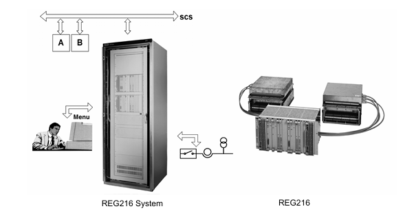
ABB REG216/REG216 Classic is a digital generator protection system designed specifically for the protection of generators and block transformers. It adopts modular hardware and software design, with extremely high installation flexibility. By combining software libraries with hardware modules, it can easily adapt to primary systems and protection solutions of different scales, providing cost-effective solutions in various application scenarios. There are two design versions of the system, with the main difference being the modules used for binary process connections: REG216 uses the E/A module 216GD61a, while REG216 Classic uses the 216GE61/216GA61 and 216GA62 modules.
Core functions and protection functions
The system has a rich library of protection functions, covering various functions required for generator and transformer protection, mainly including:
Differential protection: such as generator differential (87G) and power transformer differential (87T), suitable for three-phase and 2-3 winding transformers.
Current protection: including timed overcurrent (51), overcurrent or undercurrent with peak evaluation (50), voltage controlled overcurrent (51/27), etc.
Voltage protection: There are timed overvoltage (59), undervoltage (27), instantaneous overvoltage protection (59, 27), etc. It can also be used for stator grounding faults, rotor grounding faults, and other protections.
Other protections: such as negative sequence current protection (46), distance protection (21), power protection (32, 37), frequency protection (81), overheating protection (49), etc.
These protection functions can be selected from a comprehensive library through a personal computer, without the need for computer programming knowledge, and have a wide range of settings. The main parameters can be flexibly set.
Hardware composition
Main components: The system includes interfaces with the primary system (CT, PT, and auxiliary relays) as well as parallel buses and related electronic units (such as analog inputs and data processors), which are connected through standard prefabricated shielded cables.
Interface component: Input transformer component 216GW62 is used to adjust signal level and provide isolation; Auxiliary relays and optocoupler components are used to achieve functions such as potential separation and tripping of digital input and output signals.
Electronic unit: adopting a plug-in design, installed in a 19 “, 6U standard size equipment rack, including processing unit 216VC624, analog input unit 216EA62, digital output unit 216AB61, etc., data exchange is carried out through parallel bus B448C.
Setting and Control
Operation method: Set up and control through a personal computer connected to a serial interface. Console operation is assisted by menus, allowing for parameter settings, measurement value display, event display and printing, fault recording, and other operations.
Software Tools: Starting from firmware version V5.2, a Windows based configuration tool CAP2/316 is available, which can run on specific operating systems and supports online or offline programming.
Self monitoring and testing
Self monitoring: including continuous self-monitoring of hardware and periodic testing programs primarily executed by software.
Testing function: Various operational measurement data can be viewed, simulated numerical testing can be conducted through the “testing function” of the software HMI, and external testing equipment can be used for injection testing to achieve 100% system testing.
Redundant configuration
Hardware and software redundancy can be adjusted according to functional requirements, and two independent protection function groups can be installed in two separate hardware racks, or in only one rack but with two completely independent hardware groups.
Technical parameters
Input circuit: The rated current is 1A, 2A, or 5A, the rated voltage is 100V or 200V, the rated frequency is 50/60Hz, and there are corresponding parameters such as thermal rating.
Parameters of each protection function: Different protection functions such as generator differential, transformer differential, timed current function, etc. have their own technical parameters such as setting range, accuracy, response time, etc.
Other parameters: such as auxiliary power supply, general data (temperature range, humidity, seismic testing, etc.), mechanical design parameters, etc.
Order Information
Configuration information: When ordering, please provide information such as rated current, rated voltage, optocoupler voltage, number of different units (electronic parts) and interfaces, and refer to questionnaire 1MRB520026-Ken.
Subcode: The system has multiple subcodes corresponding to different system configurations, rated parameters, interface arrangements, etc., which can be selected according to requirements.
Attachments: including DC filter, PCC card interface, RS232C bay bus interface, human-machine interface, fiber PC connection cable, fault recorder evaluation program, etc.
The ABB VA-MC15-05 controller module plays a crucial role in industrial automation control systems. As the core control unit, it is responsible for precise monitoring and efficient regulation of the operating status of various equipment. This module, with its advanced technological architecture and outstanding performance, can work collaboratively with various industrial equipment to achieve refined management of complex production processes, effectively improving the stability, reliability, and production efficiency of industrial production processes. It is widely used in various industries such as manufacturing, energy, and transportation.
Specification parameters
Input voltage range: Supports wide input voltage and can adapt to AC input from 85V to 265V or DC input from 85V to 300V. It has strong grid compatibility and can flexibly adapt to different regions and types of power supply environments, meeting diverse industrial application needs.
Power efficiency: The power conversion efficiency is extremely high, exceeding 85%, which means that in the process of converting electrical energy, energy loss can be minimized to the greatest extent possible, converting more input electrical energy into effective working energy. This not only reduces energy consumption but also improves the overall operating economy of the equipment.
Power parameters: The maximum input power can reach 30W, and under normal operation without an expansion module, the power consumption is less than 10W. This low-power design not only helps reduce operating costs, but also reduces equipment heating, improving the stability and reliability of equipment operation.
Isolation characteristics: It has excellent electrical isolation performance, with an isolation voltage of up to DC 2500V, which can effectively isolate electrical interference between different circuits, enhance the anti-interference ability of the module in complex electromagnetic environments, and ensure accurate transmission of control signals and stable operation of equipment.
Protection function: Equipped with a comprehensive short-circuit protection mechanism, when a short-circuit fault is detected in the circuit, it can quickly respond, cut off the circuit, protect the module and connected equipment from the impact of short-circuit current damage, greatly improving the safety of equipment operation.
Relay output capability: The relay output specifications are AC 250V/3A or DC 24V/10A, which can meet the driving needs of various external devices, reliably control various actuators, and achieve precise control operations of industrial equipment.
Working principle
Signal collection: Real time collection of operating parameter signals from external devices through sensors and other devices, such as temperature sensors collecting temperature signals, pressure sensors collecting pressure signals, etc. These analog signals are converted into digital signals through an A/D conversion module for subsequent processing and analysis by the controller module.
Data processing and decision-making: The microprocessor inside the controller module performs high-speed operations and processing on the collected digital signals. Based on preset control algorithms and logic rules, the processed data is compared and analyzed with pre-set target values. If there is a deviation between the actual operating parameters and the target values, the microprocessor quickly calculates the corresponding control strategy and generates control instructions.
Control output: Based on the generated control instructions, the controller module transmits control signals to the execution mechanism of external devices through relay output, analog output, and other methods. For example, by controlling the opening and closing of relays to control the start and stop of motors, or by outputting analog voltage signals to adjust the opening of regulating valves, precise control of equipment operating status can be achieved, ensuring stable operation of equipment according to predetermined requirements.
Communication interaction: When communication with external devices or upper computers is required, the controller module uses its communication interface to upload the collected data information to the upper computer according to a specific communication protocol (such as Modbus protocol, etc.), while receiving control instructions and parameter setting information issued by the upper computer, achieving remote monitoring and intelligent management of the equipment.
Precautions
Installation environment requirements: The VA-MC15-05 controller module should be installed in a dry, well ventilated, non corrosive gas, and less dusty environment. A humid environment may cause short circuits in electronic components, corrosive gases may corrode equipment components, excessive dust may affect equipment heat dissipation, leading to decreased or even damaged equipment performance and shortened equipment lifespan. The installation location should be far away from strong electromagnetic interference sources to avoid electromagnetic interference affecting the normal operation of the module.
Electrical connection specifications: When performing electrical connection operations, it is necessary to strictly follow the requirements in the product manual for wiring. Ensure that the wiring is firm and reliable, avoid loosening, and prevent safety hazards such as heating and ignition caused by poor contact; At the same time, it is necessary to carefully check whether the wiring is correct to prevent serious electrical faults such as short circuits. Otherwise, it may not only affect the normal operation of the controller module, but also cause safety accidents and damage to personnel and equipment. When connecting the input power supply, it is necessary to confirm that the power supply voltage matches the input voltage range of the module to avoid module damage caused by voltage mismatch.
Parameter setting and maintenance: Before putting the equipment into use, it is necessary to accurately set the various parameters of the controller module based on the actual application scenario and the parameters of the controlled object, such as control mode, target value, alarm threshold, etc. Incorrect parameter settings may cause the device to malfunction or experience performance degradation. In addition, regular inspections and maintenance work should be carried out on the controller module, closely observing the operation status of the equipment, and paying attention to whether there are overheating, abnormal noise, odor and other phenomena of the components. If any problems are found, the machine should be stopped immediately and professional technicians should be contacted for repair and treatment in a timely manner. Users are strictly prohibited from disassembling the module without authorization to avoid causing greater damage.
The ABB VA-3180-10 variable speed drive is a device that plays a key role in the field of industrial automation, focusing on precise control of motor speed. It has become a core component for various industrial equipment to achieve efficient operation and precise control, thanks to its advanced technological architecture and outstanding performance. By flexibly adjusting the operating speed of the motor, this driver can effectively match the actual needs of equipment under different working conditions, significantly improving the overall operating efficiency and stability of the system. It is widely suitable for industries such as chemical, power, petroleum, and pharmaceutical industries that require strict precision and reliability in motor control.
Specification parameters
Input voltage: It can usually adapt to three-phase AC input voltage ranging from 230V to 500V, with a fluctuation range of ± 10%, and can flexibly connect to different regional power grid environments to meet diverse industrial power supply needs.
Output current: Depending on the specific application scenario and model configuration, the output current may vary, with a maximum of 1000A. The powerful current output capability ensures stable operation of motors of different power levels.
Speed regulation range: The speed regulation range can reach 1:10 to 1:100 (depending on the specific load and application scenario), which can achieve precise adjustment within a wide speed range. Whether it is for low-speed high torque heavy-duty equipment or high-speed high-precision precision equipment, it can provide accurate speed control.
Dynamic response: The response speed is extremely fast, less than 100ms (depending on the specific model), able to quickly capture and respond to load changes, adjust motor speed in a timely manner, maintain the stability of equipment operation, and effectively reduce the risk of equipment failure caused by load fluctuations.
Overload Capacity: With excellent overload protection capability, it can withstand 120% rated current for 1 minute and 150% rated current for 10 seconds. In the face of instantaneous overload situations, it can automatically limit the current, protect the driver and motor from damage, and greatly improve the reliability and safety of equipment operation.
Core functions
Precise speed regulation: With the help of high-performance control algorithms, the motor speed can be precisely controlled, with a wide range of speed regulation to meet the diverse needs of motor speed under different load conditions, ensuring the stability and efficiency of equipment operation. Whether it is fine production technology or high-power power drive, precise speed regulation can be achieved.
Soft start function: adopting advanced soft start technology, gradually increasing the starting frequency and voltage when starting the motor, effectively reducing the current shock during the starting process, reducing wear and tear on the motor and mechanical components of the equipment, extending the service life of the equipment, and reducing interference with the power grid during starting, ensuring the stable operation of the power grid.
Complete protection mechanism: Built in multiple protection functions, such as overcurrent protection. When an abnormal increase in current exceeds the set threshold is detected, the circuit is quickly cut off to prevent equipment from being burned due to overcurrent; Overload protection can automatically take measures such as speed reduction or shutdown when the motor runs under overload for a long time to protect the motor; Overvoltage and undervoltage protection ensure that the driver can automatically adjust or stop working when the power supply voltage fluctuates abnormally, avoiding equipment damage due to voltage issues; Overheating protection monitors the internal temperature of the drive in real-time. Once the temperature is too high, immediate cooling measures or shutdown protection are activated to ensure the safe operation of the equipment in all aspects.
Communication and Expansion Function: Equipped with multiple communication interfaces such as Modbus, Profibus, etc., it can achieve seamless real-time communication with the upper control system, facilitating remote monitoring and adjustment for users, and easily achieving centralized control and management of automated production lines. At the same time, the driver has good scalability and can flexibly expand input and output interfaces according to actual application needs, connecting various sensors, actuators, and other devices to meet the diverse functional requirements of complex industrial control systems.
Working principle
Rectification process: When the three-phase AC power is connected to the VA-3180-10 variable speed drive, it first enters the rectification circuit. This circuit utilizes the unidirectional conductivity of diodes to convert three-phase AC voltage into DC voltage, providing a stable DC power foundation for subsequent inverter and control processes. It integrates the AC input from the power grid into a DC form suitable for internal processing of the driver.
Inverter stage: After rectification, the DC voltage is quickly switched on and off by a series of power switching devices (such as IGBT) in the inverter circuit, converting the DC power into three-phase AC power with adjustable frequency and voltage, and outputting it to the motor. By precisely controlling the conduction and turn off time of power switching devices, changing the frequency and voltage amplitude of the output AC power, flexible adjustment of motor speed and torque can be achieved to match the operating requirements of equipment under different working conditions.
Control loop: The internal control circuit of the driver monitors the operating parameters of the motor in real time (such as current, voltage, speed, etc.) as well as external input control signals (such as speed setpoint, torque setpoint, etc.), and accurately regulates the rectification and inverter loops according to preset control algorithms. For example, when receiving a new speed given signal, the control circuit will quickly calculate and adjust the frequency and voltage of the AC power output from the inverter circuit, so that the motor speed can be quickly and stably adjusted to the target value, ensuring the accuracy and stability of the entire system operation.
Precautions
Installation environment requirements: The VA-3180-10 variable speed drive must be installed in a well ventilated, dry, non corrosive gas, and dust-free environment. Adverse environmental factors, such as humidity, may cause short circuits in electronic components, corrosive gases may corrode equipment components, excessive dust may affect equipment heat dissipation, leading to decreased or even damaged equipment performance and shortened equipment lifespan.
Electrical connection specifications: When performing electrical connection operations, it is necessary to strictly follow the requirements in the product manual for wiring. Ensure that the wiring is firm and reliable, avoid loosening, and prevent safety hazards such as heating and ignition caused by poor contact; At the same time, it is necessary to carefully check whether the wiring is correct to prevent serious electrical faults such as short circuits. Otherwise, it may not only affect the normal operation of the driver, but also cause safety accidents and damage to personnel and equipment.
Parameter setting and maintenance: Before putting the equipment into use, it is necessary to accurately set the various parameters of the driver according to the actual application scenario and motor parameters, such as speed setting, current limiting, acceleration time, deceleration time, etc. Incorrect parameter settings may cause the device to malfunction or experience performance degradation. In addition, regular inspections and maintenance work should be carried out on the drive, closely observing the operation status of the equipment, and paying attention to whether there are overheating components, abnormal noise, odors, and other phenomena. If any problems are found, the machine should be stopped immediately and professional technicians should be contacted for repair and treatment in a timely manner. Users are strictly prohibited from disassembling the drive without authorization to avoid causing greater damage.
ABB 72395-4-039123 is a power module specially designed for ABB excitation systems, playing a core role in the stable operation of the entire excitation system, providing continuous and reliable power supply. It is widely used in the industrial field, especially in scenarios involving power control, thanks to its advanced technology and excellent performance, ensuring that various devices can operate efficiently and stably.
Specification parameters
Input voltage: Refer to ABB PCD231B101 excitation control module for input voltage ranging from 380V AC to 690V AC. As a power module, 72395-4-039123 is likely to be able to adapt to similar wide AC input voltage ranges to meet the needs of different application scenarios.
Output voltage and current: Analogous to ABB UNITOL 1010 module, the output voltage is DC 0V -400V, and the output current is 0-10A. 72395-4-039123 may provide corresponding DC output voltage and current according to the excitation system requirements to supply power to the excitation winding. It is speculated that the output voltage may be in the range of tens to hundreds of volts DC, and the output current may be in the range of several amps to tens of amps.
Working temperature: Referring to other ABB excitation related modules, such as UNITOL 1010, the working temperature is -20 ° C to+60 ° C. 72395-4-039123 is expected to operate stably in the temperature range of -20 ° C to+60 ° C to adapt to different environmental temperature conditions in industrial sites.
Protection level: Referring to ABB PCD235A101 module, the protection level can reach IP54 or IP67 (depending on the specific configuration). 72395-4-039123 may also have a similar level of protection, with certain dust and water resistance, and can be used in harsh industrial environments.
Core functions
Stable power supply: providing a continuous and reliable power supply for ABB excitation system, ensuring the normal operation of various functions of the excitation system, and ensuring the stability of power transmission and control.
Energy Conversion and Regulation: Accurately convert the input AC power into DC power suitable for the excitation system, and precisely adjust the output voltage and current to meet the energy requirements of the excitation system under different operating conditions.
Working principle
Input rectification: When the AC input voltage is connected to the module, it is first converted into DC power through the internal rectification circuit. This process utilizes the unidirectional conductivity of rectifying devices such as diodes to convert alternating positive and negative AC power into unidirectional DC power, providing a foundation for subsequent circuit processing.
Filtering and voltage stabilization: After rectification, the DC power often has certain fluctuations. At this time, the filtering circuit starts to work. Through a filtering network composed of components such as capacitors and inductors, the ripple in the DC power is removed, making it smoother and more stable. At the same time, the voltage regulator circuit monitors the output voltage in real time. When the voltage fluctuates, the circuit parameters are adjusted to ensure that the output voltage is always maintained at the set stable value.
Output adaptation: After filtering and stabilizing the DC power, the voltage and current are precisely adjusted and adapted according to the actual needs of the excitation system through specific circuits and control algorithms, and output to the excitation system in the appropriate form of electrical energy to ensure its stable operation.
Key advantages
Efficient and energy-saving: By adopting advanced power conversion technology and optimized circuit design, stable power supply can be achieved while effectively reducing energy loss, improving energy utilization efficiency, and saving operating costs for enterprises.
High reliability: The product strictly follows ABB’s high standard quality control system in the design and manufacturing process, selects high-quality electronic components, undergoes multiple rigorous tests, and has excellent anti-interference ability and stability. It can operate stably for a long time, greatly reducing the risk of equipment failure and improving the reliability of system operation.
Easy installation: Its structural design is compact and reasonable, and the installation interface is standardized. In the actual installation process, it can effectively reduce installation difficulty, reduce installation time and labor costs, and be easily and quickly integrated into various ABB excitation systems.
Precautions
Installation environment: The module should be installed in a dry, well ventilated, non corrosive gas and less dust environment to avoid performance degradation or damage due to environmental factors.
Electrical connection: When making electrical connections, it is necessary to strictly follow the requirements of the product manual to ensure correct and secure wiring, prevent loosening, short circuits, and other problems, so as not to affect the normal operation of the module or even cause safety accidents.
Maintenance: Regularly inspect and maintain the module, observing for any abnormal phenomena such as overheating or damage to the components. If any problems are found, professional technicians should be contacted in a timely manner for maintenance and handling. Do not disassemble the module without authorization.
The ALSTOM NRD108031 TRVC070999000 BOTTOM high-speed counting module, as a key member of Alstom’s industrial automation product line, is designed to meet the stringent requirements for high-precision, high-speed counting and signal processing in complex industrial environments. This module, with its excellent performance, can accurately capture and process rapidly changing pulse signals, and is widely used in many fields such as automated production lines, industrial robot control, motor speed monitoring, flow measurement, etc. It plays a crucial role in improving the automation level of industrial production processes and ensuring the accuracy and stability of production processes.
Brand background
Alstom has long been renowned in the global industrial sector, particularly in areas such as rail transit, power equipment, and power transmission infrastructure. The company has a profound technical background and rich industry experience, and is committed to providing customers with high-quality solutions through innovative technology for a long time. Its products are renowned for their advanced technology, reliable quality, and outstanding performance. This high-speed counting module inherits Alstom’s brand advantages, embodies the company’s research and development achievements in the field of industrial control, and fully demonstrates Alstom’s continuous efforts and leading position in promoting industrial automation processes.
Core functions
High speed pulse counting
Capable of accurately counting input pulse signals at extremely high speeds, whether in high-speed motor speed monitoring scenarios or in counting applications on rapidly running automated production lines, it can quickly and accurately record the number of pulses, providing key data for equipment operation status monitoring and production process control.
Encoder signal processing
For complex signals output by encoders, such as AB phase orthogonal encoded signals, the module can efficiently decode and process them. By analyzing the phase relationship of AB phase pulse signals, not only can the rotational speed of rotating equipment be accurately calculated, but its rotation direction can also be determined, playing a core role in applications such as industrial robot motion control and CNC machine positioning that require extremely high position and velocity accuracy.
Data collection and transmission
Real time collection of pulse signal related data, and rapid transmission of processed counting results, frequency information, and other data to other industrial automation equipment connected to it through internal high-speed data processing channels, such as programmable logic controllers (PLCs), industrial computers, etc., to achieve data sharing and interaction, providing a data foundation for the decision-making and operation of the entire automation control system.
Frequency measurement and conversion
It can accurately measure the frequency of input pulse signals and convert the measured frequency information into a standard data format that is easy for other devices to understand and process according to system requirements. It has important applications in industrial application scenarios involving frequency analysis, such as flow measurement and vibration monitoring.
Precautions
Installation points
When installing modules, it is necessary to choose an environment with good ventilation, dryness, and away from strong electromagnetic interference sources to avoid adverse environmental conditions affecting the normal operation of the module. Strictly follow the instructions in the installation manual for wiring operations, ensuring that the wiring is firm and correct, and preventing signal transmission abnormalities or even module damage caused by loose or incorrect wiring. In addition, according to the protection level requirements of the module, it is necessary to avoid installation in environments that exceed its protection capabilities, such as high humidity, dusty or corrosive gas environments.
Operation and maintenance
Regularly inspect and maintain the module, clean the dust and debris on the surface of the module, ensure good heat dissipation, and avoid overheating of the module due to poor heat dissipation, which may affect performance. Check whether there are signs of aging or damage to the connecting lines, replace the damaged lines in a timely manner, and ensure the stability of signal transmission. During the operation of the module, avoid frequent power switch operations to prevent instantaneous current surges from damaging the module. At the same time, attention should be paid to monitoring the operating temperature, voltage, and other parameters of the module to ensure that it operates within the normal range.
Parameter settings
Before setting parameters, it is necessary to carefully read the user manual, deeply understand the meaning and function of each parameter, and carefully set various parameters such as counting mode, pulse frequency range, communication protocol, etc. according to actual industrial application scenarios and control requirements. After the parameter settings are completed, comprehensive testing and verification are required to ensure that the module can work as expected. If any abnormalities are found, the parameter settings should be checked and adjusted in a timely manner.
Application scenarios
Automated production line
On various automated production lines, this module is used to accurately count the quantity of products, monitor production progress in real-time, and ensure efficient and orderly production processes. At the same time, the operating speed of various equipment on the production line can be monitored and controlled, such as the operating speed of conveyor belts, the operating frequency of robotic arms, etc. By accurately controlling the operating parameters of the equipment, product quality and production efficiency can be improved.
Industrial Robot Control
In the motion control of industrial robots, the module processes the encoder signal to accurately calculate the rotation angle and displacement of the robot joints, achieving precise control of the robot’s motion trajectory. Whether in tasks such as handling, assembly, or welding, it can ensure that the robot completes operations accurately and without errors, improving the application accuracy and reliability of industrial robots in the production process.
Motor speed monitoring and control
For various types of motor equipment, the module can monitor the motor speed in real time and provide feedback on the speed information to the control system. The control system adjusts the speed of the motor based on feedback data to meet the requirements of different production processes for motor speed. This module can provide accurate data support for motor start, stop, and speed adjustment during operation, ensuring stable and efficient operation of the motor.
Flow measurement
In fluid transportation systems in industrial production, such as chemical, petroleum, water supply and drainage industries, modules can count and measure the frequency of pulse signals output by flow meters, thereby accurately calculating the flow rate of fluids. By monitoring and controlling the flow rate in real-time, it ensures stable fluid supply during the production process, meets the strict requirements of the production process for flow rate, and also helps to achieve rational energy utilization and cost control.
The ALSTOM CMU 42015-115-00 control module is a high-performance industrial control module launched by Alstom, specifically designed for industrial automation systems. It can provide precise and stable control services for various equipment and production processes in complex and changing industrial environments. With excellent performance, it is widely used in many industries such as power generation, manufacturing and processing, and process automation. It is a key component in the field of industrial automation to ensure efficient and reliable operation of the system, providing strong support for the intelligent and automated development of industrial production.
Brand background
Alstom is a globally renowned supplier of rail transit, power equipment, and power transmission infrastructure, with a long history and profound technological accumulation. The company has strong research and development capabilities and rich experience in energy, transportation, and other fields, and is always committed to providing customers with innovative, efficient, and reliable solutions. Its products are renowned for their high quality, high performance, and advanced technology, occupying an important position in the global market. As an important component of the industrial automation field, ALSTOM’s control module series products inherit the company’s consistent technological advantages and quality commitments, and are widely used in various industrial fields to help industrial production achieve automation and intelligent upgrades.
Specification parameters
Working voltage: 220V, compatible with common industrial power standards, capable of efficient operation under stable power supply, ensuring stable output of control commands.
Output frequency: 50kHz, precise frequency output can ensure precise control of equipment operation rhythm, meeting the strict requirements of control frequency in different industrial scenarios.
Size: 16.7cm × 14.8cm × 5.5cm. The compact design allows it to be flexibly installed in various control cabinets or equipment spaces, saving valuable installation space.
Weight: 0.6kg. The lightweight design not only facilitates transportation and handling, but also reduces operational difficulty during equipment installation.
Certification: Compliant with multiple international certification standards such as CE, UL, RoHS, etc., this means that the control module has reached internationally recognized levels in terms of safety, quality reliability, and environmental friendliness.
Protection level: up to IP65, with excellent dust and water resistance, can effectively resist dust particles and water splashes from all directions in industrial environments, and can work stably even in harsh working conditions.
Core functions
Accurate parameter control
It can accurately monitor and regulate various parameters in the industrial production process, including analog parameters such as equipment operating speed, temperature, pressure, as well as digital signals such as equipment start stop and valve opening and closing, ensuring that the production process strictly follows the preset process requirements.
Data collection and processing
It can collect various data information from sensors and other devices in real time, process and analyze the data quickly, provide accurate basis for control decisions, and upload the processed data to the higher-level control system to achieve data sharing and interaction.
Fault diagnosis and alarm
Equipped with comprehensive fault diagnosis functions, it can timely detect the fault information of the module itself and the controlled equipment, and remind operators in a timely manner through alarm signals, facilitating quick troubleshooting and problem-solving, and reducing the impact of faults on production.
Communication and linkage
Support communication with other industrial automation equipment, such as programmable logic controllers (PLCs), human-machine interfaces (HMIs), etc., to achieve information transmission and linkage control, and jointly build a complete automation control system.
Precautions
Installation aspect
When installing, choose a location with good ventilation, away from strong electromagnetic interference sources, and low vibration to ensure a stable working environment for the module. During the installation process, it is necessary to strictly follow the requirements of the installation manual to ensure correct and secure wiring, and to avoid module damage or abnormal operation caused by wiring errors. At the same time, it is important to pay attention to the protection level requirements of the module and avoid installing and using it in environments that exceed its protection capabilities.
Operation and maintenance
Regularly inspect and maintain the module, clean the dust and debris on the surface of the module, and ensure good heat dissipation. Check if the connecting wires are loose or aging, and promptly address any issues found. Prevent the module from running at full load for a long time to extend its service life. When conducting maintenance and repairs, the power must be cut off first to prevent electric shock accidents.
Parameter settings
Before setting parameters, carefully read the user manual and correctly set various parameters according to actual production needs to avoid a decrease in control accuracy or equipment failure caused by incorrect parameter settings. After the parameter settings are completed, testing and verification should be carried out to ensure that the module can work properly.
The GE P40 Agile series includes intelligent electronic devices (IEDs) such as P14N (non directional feeders), P14D (directional feeders), and P94V (voltage and frequency), designed to provide comprehensive protection, control, and monitoring functions for power systems. This series of products integrates the design rigor and technology of transmission applications, suitable for new construction and renovation projects in public utilities and industrial markets. It can be applied to scenarios such as overhead lines, underground cables, busbars, circuit breakers, transformers, reactors, and distributed generation, supporting various applications from distribution (as primary protection) to transmission voltage levels (as backup protection), and is suitable for direct grounding, resistance grounding, and arc suppression coil systems.
Model and Application
Different models are based on different hardware foundations and are suitable for different application scenarios, paired with different chassis models, as follows:
Model, hardware foundation, expected application, chassis model
P14NB、P14N、 Non directional feeder, 20, 30 or 40TE
P14NZ、P14N、 Non directional feeder with HIF, 20, 30 or 40TE
P14DA、P14D、 Directional feeder line compatible with 20TE chassis, 20TE
P14DB、P14D、 Directional feeder, 20, 30 or 40TE
P14DH、P14D、 Directional feeder with power direction grounding fault, 30TE or 40TE
P14DG、P14D、 Distributed generation, 30TE or 40TE
P14DL、P14D、 Advanced directional feeder protection (with automatic reclosing and fault locator), 20, 30 or 40TE
P14DZ、P14D、 Advanced directional feeder with HIF or TEFD, 30TE or 40TE
P94VB、P94V、 Voltage and frequency, 20, 30 or 40TE
P94VP、P94V、 Voltage and frequency with synchronous inspection, 20, 30 or 40TE
P94VR、P94V、 Voltage and frequency with automatic reclosing and synchronization check, 20, 30 or 40TE
(Note: TEFD is for transient grounding fault detection; HIF is a high impedance fault)
Core functions
Protection and control
It has comprehensive current, voltage, power, and frequency protection functions, including multi-stage independent protection components, multiple curves (4 setting groups), high impedance faults, load intrusion, switch closure to faults, and fault locators.
Support functions such as rate of change, automatic reclosing for all schemes, TEFD, and synchronization check.
Measurement and Monitoring
Provide comprehensive metering and power on diagnostic functions, including two-level circuit breaker faults and circuit breaker status monitoring.
Support switch device monitoring, including CT/VT, DC power supply, complete trip circuit monitoring, circuit breaker faults, switch control and status (up to 8), as well as up to 2048 events and 10.5 second disturbance records.
Advanced communication
Up to two Ethernet ports, optional redundancy protocol (RSTP or PRP/HSR).
Supports SNTP or IRIG-B time synchronization, multiple communication protocols including IEC 61850, Modbus, DNP 3.0, IEC 60870-5-103, and Courier/K-Bus, and supports simultaneous operation of IEC 61850 and DNP3 Ethernet protocols.
Ease of Use
Compact and withdrawable design, available in 4-inch, 6-inch, and 8-inch size options.
Through programmable binary input voltage, universal CT, and simplified standardization of power supply, seamless migration with K-series relays is achieved, facilitating on-site relay upgrades.