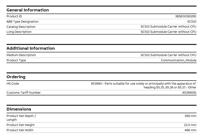
Media description: Consistent with the product name, clearly defining its functional positioning as a “CPU free submodule carrier”
Ordering and Customs Information
HS code: 853890, classified as “parts (other) applicable to equipment under items 85.35, 85.36, or 85.37”, belonging to the category of industrial control equipment related accessories.
Customs tariff number: 85389091, providing a basis for specific customs clearance and tax declaration.
Physical specifications
Size parameters:
Net depth/length: 288mm
Net height: 22.5mm
Net width: 486mm
Weight: Net weight 0.67kg, belonging to lightweight design, easy to install and integrate into various control systems.
Environmental and Compliance Information
RoHS compliance: Complies with the EU Directive 2011/65/EU, which restricts the use of certain hazardous substances (such as lead, mercury, etc.) in electronic and electrical equipment and meets environmental requirements.
WEEE category: classified as “5 Small equipment (with all external dimensions not exceeding 50 centimeters) “is applicable to the recycling and disposal standards for electronic and electrical equipment waste.
Battery situation: Number of Batteries is 0, no need to rely on battery power supply, reducing maintenance costs and environmental risks.
SCIP Information: Number 64ca723a-0669-4eec-a128-1d20dd256d13, registered in Sweden (SE), meets the requirements of the European Union Regulation on the Registration, Evaluation, Authorization and Restriction of Chemicals (REACH) regarding the transmission of item information.
Associated suite
3BSE011302R1: AMHWV16 HW PM510V16 SC510 and MB510, Kit
3BSE016433R1: Unclear description, Kit
3BSE016434R1: Unclear description, Kit
Product category
This product belongs to multiple control systems and communication module categories, reflecting its wide compatibility and application scenarios:
Control system products – Control and communication – AC 400- Communication module – SC510 submodule carrier – SC510 submodule carrier
Control System – Advant OCS with Master SW – Controller – Advant Controller 450- Advant Controller 450 Version 2.3- Communication Module
Control System – Advant OCS with Master SW – Controller – Advant Controller 450RMC – Advant Controller 450RMC 2. x – Communication Module
Control System Advant OCS with MOD 300 SW Controller AC460 Communication Module
Product Function and Positioning Speculation
Based on the attributes of “submodule carrier” and “communication module”, the core functions of SC510 can be inferred as follows:
As the installation and connection carrier for submodules, it provides physical interfaces and electrical connection support for other functional submodules (such as input/output modules, signal processing modules, etc.).
Participate in communication and interaction within the control system, assist in data transmission and collaborative work between different modules and controllers, and ensure the overall stability and efficiency of the system.
Due to the “CPU free” design, its functionality focuses more on hardware level carrier and communication adaptation, relying on external controllers (such as Advant Controller 450, AC460, etc.) to achieve complex logic control.
Applicable scenarios
Based on its category and associated suite, SC510 is mainly used in industrial automation control systems, especially ABB’s Advant OCS, AC 400 and other series control systems, which can be used for:
Equipment Control and Communication Integration in Manufacturing Production Lines
Construction of automated monitoring systems for industrial processes such as chemical, energy, and water treatment
Modular connection and collaborative operation of various subsystems in large industrial equipment
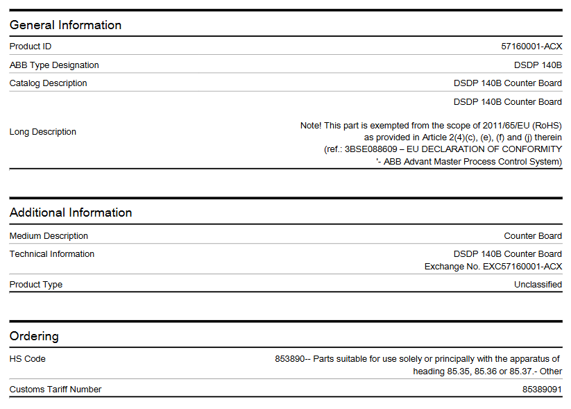
The DSDP 140B counter board, product ID 57160001- ACX, is a high-performance product carefully crafted by ABB for industrial automation control systems. Its main function is to achieve precise counting and play a key role in various complex industrial scenarios, helping to improve production efficiency and control accuracy.
Product Core Information
Product Name: DSDP 140B Counter Board
Product identification:
Product ID: 57160001-ACX
ABB model name: DSDP 140B
Physical specifications
Size:
Net depth/length: 350mm
Net height: 20mm
Net width: 255mm
Weight: Net weight is 0.44kg
Environmental and Compliance Information
RoHS status: Compliant with EU Directive 2011/65/EU requirements
WEEE category: 5 Small devices (all external dimensions do not exceed 50 centimeters)
Battery condition: No batteries included (Number of Batteries is 0)
Product category
This product belongs to multiple control systems and I/O module categories, as follows:
Control System Products – I/O Products – S100 I/O – S100 I/O – Modules – DSDP 140B Positioning Module
Control System -800xA – I/Os – S100 I/O – I/O Modules
Control System – Advance OCS (with Master software) – Controller – MasterPiece 200 and 200/1- I/O modules
Control System – Advant OCS (with Master software) – I/Os – S100 I/O – I/O Modules
Control System – Advant OCS (with MOD 300 software) – I/Os – S100 I/O – I/O Modules
Control System – Compact Product Suite – I/Os – S100 I/O – I/O Modules
Core functions
Accurate counting: With high-speed counting technology, it is possible to accurately count the number of products and equipment operation times on the production line, providing accurate data support for production management. For example, on an automotive parts production line, the number of parts produced per hour can be accurately counted.
Speed measurement: By analyzing the frequency of the input signal, it is possible to quickly calculate the operating speed of the equipment, such as the running speed of the conveyor belt, the speed of the motor, etc., to help operators understand the operating status of the equipment in a timely manner and optimize the production process.
Position control: By combining the characteristics of input signals and counting results, precise control of equipment position can be achieved, which plays an important role in the positioning operation of automated mechanical equipment, ensuring that the equipment accurately reaches the designated position and improving production accuracy.
Precautions
During the installation process, it is essential to ensure that the power is cut off to prevent electric shock hazards and equipment damage caused by misoperation. At the same time, it is necessary to strictly follow the steps in the product installation manual to ensure correct and secure installation.
When connecting with other devices, it is necessary to carefully check whether the input and output voltage, signal type, and other parameters match, in order to avoid equipment failure or damage caused by parameter mismatch. For example, if a device with mismatched voltage is connected to the input port of the DSDP 140B counter board, it may burn out the circuit inside the board.
During use, pay attention to the temperature and humidity of the working environment. If it exceeds the specified working temperature range (-40 ° C to 70 ° C), it may affect the performance and lifespan of the equipment; Excessive humidity may cause problems such as circuit board short circuits. Therefore, try to install the equipment in a dry and well ventilated environment as much as possible.
Regularly maintain and inspect the equipment, such as checking whether the connection lines are loose and whether the equipment is operating normally. If any abnormal situation is found, the machine should be stopped in a timely manner for troubleshooting and maintenance to prevent the fault from expanding.
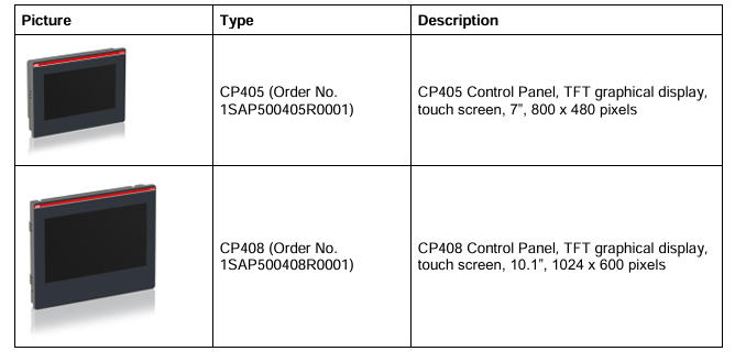
ABB CP405 is an industrial grade touch screen control panel designed specifically for discrete automation and various industrial HMI (Human Machine Interface) applications, suitable for industrial environments that require intuitive operation and monitoring. It adopts 7-inch TFT graphical display and resistive touch screen, which needs to be programmed and operated with CP400PB Panel Builder 400 software to achieve complex control logic and data visualization functions.
The order number of this product is 1SAP500405R0001, which complies with multiple international standards, including EMC Directive 2004/108/EC, RoHS Directive 2011/65/EC, etc. It has CE certification and can operate reliably in industrial environments.
Technical Parameter
Display and Touch
Screen specifications: 7-inch WVGA TFT LCD display screen with a resolution of 800 × 480 pixels, supporting 65536 colors, and capable of presenting various data and graphics clearly.
Touch screen: Adopting a 4-wire analog resistive touch screen, supporting over 1 million touch operations to ensure long-term reliability.
Backlight: LED backlight with a brightness of 250 cd/m ², with a backlight lifespan of up to 20000 hours at 25 ° C, and the brightness can be adjusted through the touch panel.
**Viewing angle * *: In industrial indoor environments, the vertical viewing angle is 140 ° and the horizontal viewing angle is 130 °, making it easy to view screen content from different angles.
Storage and Clock
User memory: Contains 8 MB NOR Flash and 128 MB NAND Flash, providing ample space for application and data storage.
Recipe Memory: Supports Flash storage or 128 kB battery backup RAM for convenient storage and retrieval of various recipe data.
Real time clock: Equipped with hardware clock/calendar function, powered by a 3 V 220 mAh lithium manganese dioxide (Li/MnO ₂) battery. Even when not in use and the ambient temperature is 20 ° C, the battery capacity can still maintain 95% after 5 years, ensuring accurate clock operation.
Interface and power supply
Serial port: equipped with RS-232, RS-485, RS-422 serial ports (Sub-D 9 female connector), can communicate with PLC or other controllers.
USB port: 1 USB Type A port, used to connect typical peripherals such as printers; 1 USB Type B port for programming.
Power supply: Input voltage is 24 VDC ± 10%, maximum power consumption is 10 W.
Weight: The net weight is 0.55 kg, and the total weight is 0.75 kg.
Environment and Protection
Working environment: The working temperature range is 0…+50 ° C (32… 122 ° F), and the working humidity is 10… 90% relative humidity (no condensation at 40 ° C), which can adapt to various environmental conditions in industrial sites.
Storage environment: The storage temperature range is -20…+60 ° C (-4… 140 ° F), and the storage humidity is 95% relative humidity (no condensation at 60 ° C), making it convenient for product storage and transportation.
Protection level: The front panel protection level is IP66 (requires correct installation), which can effectively prevent dust and water from entering.
Anti interference capability: Meets multiple electromagnetic compatibility standards, such as electrostatic discharge immunity testing (8 kV air discharge, 4 kV contact discharge), radiated RF electromagnetic field immunity testing, etc., to ensure stable operation in complex electromagnetic environments.
Functional Features
Software support
Run CP400PB Panel Builder 400 Runtime software, which supports offline and online simulation, facilitating program development and debugging.
It has rich HMI functions, including data acquisition, alarm processing, scheduler, recipe management, user and password management, etc., which can meet the diverse needs of industrial control.
Supports multilingual applications, making it easy to create and manage multilingual applications to meet the usage needs of different regions around the world, including Far Eastern languages.
Provide powerful scripting languages for automated HMI applications, and script debugging capabilities can improve application development efficiency.
Communication ability:
Support communication with AC500/AC500eCo PLC, Motion drivers and other devices;
Recommend using TK407 communication cable (order number 1SAP500467R0001) to connect AC500 series PLC.
Durability:
Backlight lifespan of 20000 hours (at 25 ° C);
The front panel film has a lifespan of 10 years in an environment without direct sunlight at 25 ° C.
Installation and Connection
Installation requirements:
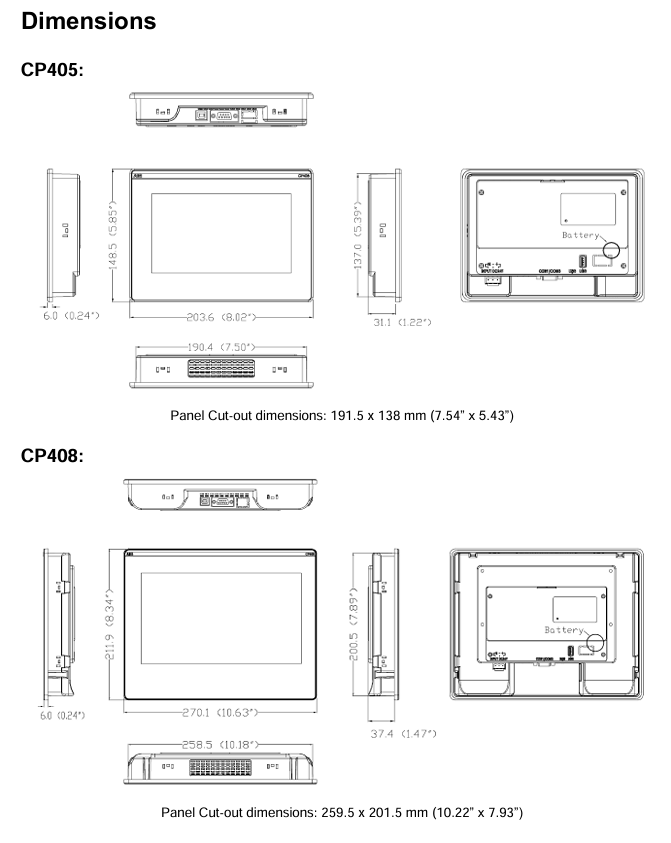
Panel opening size: CP405 is 191.5 × 138 mm, CP408 is 259.5 × 201.5 mm;
Ensure that the installation surface is flat and the gasket is well sealed to maintain IP66 protection.
Wiring:
Power supply: Connect 24 VDC through terminal and ground (terminal 3);
Serial port pin definition: Supports RS-232 (TxD/RxD), RS-485 (±), RS-422 (TxD ±/RXD ±).
Battery maintenance: The built-in non rechargeable lithium battery is used for clock backup and must be disposed of according to local regulations.
Operation and Settings
Panel Settings: Configure display brightness, touch calibration, date and time, communication parameters, etc. through the “Panel Setup” menu.
Programming and Debugging: Connect to a PC via USB Type B interface, download the project using CP405/CP408 Panel Builder 400 software, and support automatic runtime updates.
Cleaning and maintenance: Use only a soft cloth and neutral cleaning agent to wipe, avoid touching the touch screen with solvents or tools.
Scope of application: Suitable for ACS580 frequency converters with firmware version ASCDX 2.05, only compatible with CCU-23 and CCU-24 control units, firmware types (ASCD2, ASCD4) distinguished by frame size (R1-R5, R6-R11)
Startup and Control
Start the process
Complete language selection, motor parameter configuration (refer to motor nameplate), direction testing, and other steps through the “First Start Assistant” on the auxiliary control panel.
Support control of start/stop, speed adjustment, and motor identification run (ID run) through I/O interface for optimizing motor control parameters.
Control mode
Local control: Operated through the control panel or PC tools, suitable for debugging and maintenance.
External control: Remote control is achieved through I/O terminals (digital/analog inputs) or fieldbus (embedded Modbus RTU or optional adapter), supporting the switching of two external control positions, EXT1 and EXT2.
Control panel functions
Layout and buttons: including display screen, directional keys, start stop keys, local/remote switch keys, etc., supporting shortcut key operations (such as taking screenshots, adjusting brightness).
Main menu:
Basic settings: Configure control macros, motor parameters, ramp time, limit values, etc.
I/O menu: View and adjust the configuration of digital/analog input/output.
Diagnostic menu: displays faults, warnings, restriction status, and event logs.
Energy Efficiency Menu: Monitor energy consumption, energy-saving data, and CO ₂ emission reduction.
Controlling macro
Pre defined parameter configuration set, simplifying the settings for specific applications, including:
ABB standard macro: default configuration, supports 2-wire control and 3 fixed speeds.
3-wire macro: suitable for instantaneous button control.
PID macro: used for process PID control (such as pressure and flow regulation).
PFC macro: Pump and fan control, supporting linkage of multiple devices.
Other macros: such as manual/automatic switching macro, motor potentiometer macro, etc., suitable for different scenarios.
Core functions
motor control
Supports scalar control (default, suitable for simple scenarios) and vector control (requires ID operation, suitable for high-precision speed regulation).
Speed/frequency reference values can be set through analog input, digital input, fieldbus, and other methods.
Support functions such as acceleration/deceleration ramp adjustment, constant speed control, and critical speed avoidance.
Pid control
Built in 2 sets of PID controllers for closed-loop control of process variables such as pressure and liquid level, supporting sleep/wake function for energy saving.
Protection function
It includes fixed protections such as overcurrent, overvoltage, undervoltage, and motor overheating, as well as programmable external event protection.
Support safety functions such as automatic fault reset and safe torque shutdown (STO).
Communication function
Built in Modbus RTU fieldbus interface, supporting the extension of PROFINET, EtherNet/IP and other protocols through adapters.
Parameter configuration
Parameter groups: covering actual value monitoring (01 group), input reference (03 group), faults and warnings (04 group), I/O configuration (10-15 groups), control mode (19 groups), PID settings (40-41 groups), etc., a total of 99 parameter groups.
Parameter recovery: supports resetting to default values, clearing fault logs, and backing up and restoring configurations.
Fault diagnosis
Warning and Fault: Detailed list of fault codes (such as overcurrent and overvoltage), possible causes, and solutions, supporting viewing of historical records through the control panel or event log.
Fieldbus diagnosis: Monitor communication status, send and receive data, and assist in troubleshooting bus faults.
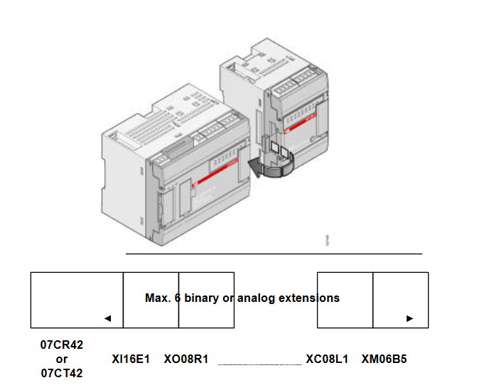
07CR42 and 07CT42 are expandable independent central units in the AC 31 automation system, suitable for various applications with input/output points ranging from 14 to 110. Its design makes it easy for both beginners and experienced automation users to operate, with components installed close to sensors/actuators. It supports integration with other automation systems in the enterprise through communication interfaces such as MODBUS and ASCII, expanding application possibilities.
Basic configuration rules
The AC 31 system must include a central unit, and both 07CR42 and 07CT42 integrate a certain number of binary inputs/outputs and analog inputs.
The number of inputs/outputs can be increased by adding input/output expansion units directly connected to the central unit, supporting up to 6 binary or analog expansion units.
Product model and reference information
07 CR 42-24VDC: Includes 8 isolated 24V DC inputs, 6 250V AC/2A relay outputs, 3 analog inputs (2 ± 10V voltage inputs and 1 temperature input), with RS232 interface, 24V DC power supply, 1SBP260023R1001
07 CR 42-120/230VAC: The input and output configuration is the same as the 24VDC version, with a power supply of 120/230V AC and a 24V DC output for input power supply. 1SBP260024R1001
07 CT 42-24VDC: Includes 8 isolated 24V DC inputs, 6 24V DC/0.5A transistor outputs, 3 analog inputs (2 ± 10V voltage inputs and 1 temperature input), with RS232 interface, 24V DC power supply, 1SBP260025R1001
Technical specifications
General characteristics
Characteristics: 07 CR 42 24V DC 07 CT 42 24V DC 07 CR 42 120/230V AC
I/O quantity
-Integrated binary input 8 8 8
-Integrated binary output 6 6 6
-Integrated analog input 3 3 3
-Analog potentiometer 2 2 2
-Maximum number of expansion units per central unit 6 6 6
-Maximum binary input number 104 104 104
-Maximum binary output 54 54 54
-Maximum number of analog inputs 51 51 51
-Maximum analog output 12 12 12
Interface without CS 31 interface, 1 RS232 interface (programming, MODBUS or ASCII) without CS 31 interface, 1 RS232 interface (programming, MODBUS or ASCII) without CS 31 interface, 1 RS232 interface (programming, MODBUS or ASCII)
Memory
-User program memory size (without ONLINE), 17000 words (approximately 8.5k instructions), 17000 words (approximately 8.5k instructions), 17000 words (approximately 8.5k instructions)
-User program memory size (with ONLINE), 8000 words (approximately 4k instructions), 8000 words (approximately 4k instructions), 8000 words (approximately 4k instructions)
-User program memory and constants, flash EEPROM, flash EEPROM, flash EEPROM
-Data memory SRAM、SRAM、SRAM
-Data backup, with battery, can be backed up for 20 days at 25 ° C, fully charged in 12 hours, with battery, can be backed up for 20 days at 25 ° C, fully charged in 12 hours, with battery, at 25 ° C
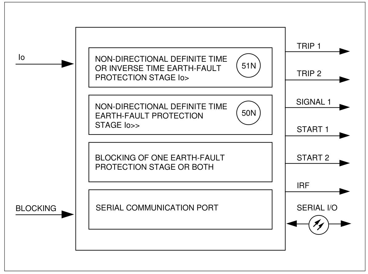
SPAJ 110 C is a non directional grounding fault relay designed for direct grounding or low resistance grounding power systems, used for selective grounding fault protection, and can be used as primary or backup protection. This relay consists of two protection stages: a low setting overcurrent stage (I ₀>) and a high setting overcurrent stage (I ₀>>). The low setting stage can choose between timed or inverse timed characteristics, while the high setting stage only supports timed characteristics and is suitable for ground fault protection of equipment such as feeders, transformers, generators, and motors.
Core functions
Protection function
Low setting neutral line overcurrent stage (I ₀>): Supports timed or inverse time characteristics (compliant with BS 142 and IEC 60255 standards, providing four types of curves: normal inverse time, extraordinary inverse time, extreme inverse time, and long-term inverse time).
High setting neutral line overcurrent stage (I ₀>>): Only supports timed characteristics and can be set to exit operation (∞).
The output relay function can be freely configured, supporting external locking signal input, and can be used in conjunction with residual voltage relays to achieve locking/unlocking operations.
Monitoring and recording
Digital display of set values, measured neutral current, memorized fault values, etc.
Record data such as maximum measured current, number of startups in each stage, and recent startup duration.
Communication and Self Inspection
The serial interface supports connecting fiber optic buses, substations, and network control systems.
Continuous self-monitoring function, automatically diagnose hardware and software faults, and trigger alarms when faults occur.
Specification parameters
Current input
Rated current (I ₙ): 1A or 5A (selected through terminals 25-27 or 25-26).
Thermal endurance: It can continuously carry 4A at 1A rated current and 20A at 5A rated current.
Dynamic current tolerance (half wave value): 250A at 1A and 1250A at 5A.
Output contact
Trip output (65-66, 68-69): rated voltage 250V AC/DC, continuously carrying 5A, can be connected and carrying 30A within 0.5s.
Signal contacts (70-71-72, etc.): rated voltage 250V AC/DC, continuously carrying 5A.
Auxiliary power supply
Module type SPTU 240 S1:80… 265V AC/DC.
Module type SPTU 48 S1:18… 80V DC.
Power consumption: about 4W statically and about 6W during operation.
Setting Range
Low setting current (I ₀>): 0.1… 0.8 × I ₙ.
High setting current (I ₀>>): 0.1… 4.0 × I ₙ or ∞ (exit).
Action time: 0.05… 100 seconds (divided into three levels).
Working principle
The relay measures the neutral line current (I ₀) through a current transformer. When the current exceeds the starting value of the low setting stage (I ₀>), the relay starts and acts after reaching the set action time; The high tuning stage (I ₀>>) is the same, but only supports timed features. The external locking signal can be input through terminals 10-11 to lock any stage or lock two stages simultaneously. When a fault occurs, the relay outputs an alarm signal, a trip signal, or activates an external automatic reclosing relay according to the configuration.
Key advantages
High flexibility: The output relay can be freely configured to adapt to different application scenarios; Support the implementation of complex protection logic in conjunction with residual voltage relays.
Strong reliability: With continuous self-monitoring function, it can detect hardware and software failures and trigger alarms, ensuring the reliability of the relay itself.
Easy to integrate: Supports serial communication interface, can be connected to fiber optic bus and control system, convenient for remote monitoring and data transmission.
Accurate measurement and recording: Digital display of key parameters, recording of fault data, facilitating fault analysis and system optimization.
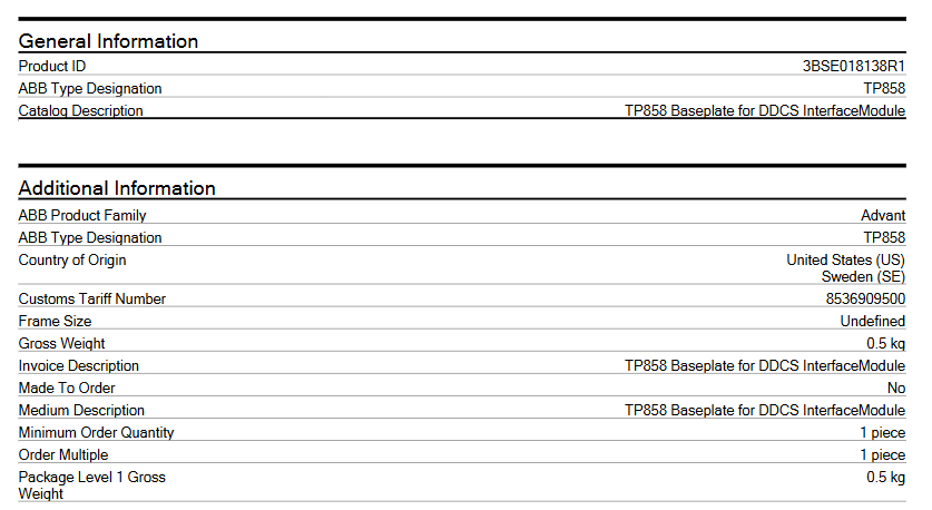
The ABB TP858 base, as a module terminal unit specially designed for distributed digital control system (DDCS) interface modules, plays a key role in industrial automation control systems. Its design aims to provide a stable installation foundation and reliable connection support for specific interface modules, ensuring the stable operation of the entire system communication and control. This base is mainly compatible with DDCS interface modules such as CI858K01 and CI872K01, and is an important component of ABB’s construction of efficient and stable industrial control systems.
Basic information
Product identification: The product number is 3BSE018138R1, the model is TP858, the product name is “Module Termination Unit”, and the catalog description is “TP858 Baseplate for DDCS Interface Module” (used as the base for DDCS interface modules).
Product attribute: Belonging to the ABB Advant product series, it is a brand new component (Part Type: New), non customized product (Made To Order: No), and does not involve exclusive quotation (Quote Only: No).
Specification and weight
The Gross Weight and Product Net Weight are both 0.5 kg.
The frame size is’ Undefined ‘.
Customs code: 8536909500.
Environmental classification: The WEEE category is “Product Not in WEEE Scope”.
Adaptation module: The technical information mentions that it is applicable to DDCS interface modules CI858K01 and CI872K01.
Core functions
Installation support: Provide a stable and safe installation environment for the DDCS interface module, ensuring that the module’s performance is not affected by factors such as vibration and displacement during operation. Through a standard installation structure, the interface module can be easily fixed in the designated position of the control cabinet or equipment, ensuring the stable operation of the module in complex industrial environments.
Connection communication: The base is equipped with necessary connection interfaces, responsible for signal transmission and communication between the interface module and other devices. Whether it is data exchange with field devices such as sensors and actuators, or instruction transmission with the upper control system, the TP858 base can provide a reliable physical connection path to ensure stable and accurate signal transmission.
System integration: As a key foundational component of system integration, the TP858 base can organically integrate multiple interface modules into a unified control system. It builds a bridge for collaborative work between different functional modules, helps to construct a complete and efficient industrial automation control network, and improves the operational efficiency and reliability of the entire system.
Precautions
Installation environment: It should be installed in a dry, well ventilated, and non violent vibration environment, avoiding installation in places with high temperature, high humidity, or corrosive gases to prevent damage to the base and modules and affect system performance. It is recommended to control the ambient temperature between 0-50 ℃ and the relative humidity not exceeding 90% (without condensation).
Installation operation: During the installation process, it is necessary to strictly follow the operation manual. Before installation, it is necessary to ensure that all equipment is powered off to avoid safety accidents such as short circuits caused by live operation. During installation, it is necessary to ensure that the base is tightly and stably connected to the interface module, and that all interfaces are correctly connected to prevent signal transmission abnormalities caused by loose connections.
Maintenance: Regularly inspect the base and connected modules for looseness, damage, and other issues. If any problems are found, they should be dealt with promptly, such as tightening loose parts, replacing damaged bases or modules. At the same time, it is necessary to keep the surface of the equipment clean and avoid dust accumulation that may affect heat dissipation and electrical performance.
Application scenarios
In the field of industrial automation, it is widely used in automation control systems in industries such as manufacturing, energy, transportation, and construction. For example, in the automated production line of an automobile manufacturing factory, the TP858 base is equipped with relevant interface modules, which can be used to connect various sensors (such as position sensors, pressure sensors) and actuators (such as motors, cylinders), achieve precise control and data acquisition of production line equipment, and ensure efficient and stable operation of the production line.
Process control system: used in petrochemical, metallurgical, papermaking and other process industries to collect process data (such as temperature, pressure, flow rate, etc.) and control actuators (such as regulating valves, pumps, etc.). Through the collaborative work of TP858 base and interface module, real-time monitoring and precise control of the production process are achieved, ensuring the safety and stability of the production process, and improving product quality and production efficiency.
Energy industry: plays an important role in energy production and distribution systems such as electricity and water conservancy. For example, in power plants, it can be used to connect power monitoring equipment and control systems, achieve real-time monitoring and control of the operating status of power generation equipment, and ensure stable and reliable power supply; In hydraulic engineering, it can be used to control equipment such as water gates and pumps, achieving rational allocation and management of water resources.
Infrastructure field: In the construction of infrastructure such as water supply and drainage, sewage treatment, etc., the TP858 base with interface modules can be used to control related equipment, such as the start and stop of water pumps, the opening and closing of valves, etc., to achieve automated management of infrastructure operation, improve operational efficiency, and reduce maintenance costs.
Product identification: Product number EXC3BSC610037R1, model SD821, product type Power Supply Device, described as “SD821 Power Supply Device Exchange”.
Additional note: The replaced parts must be returned through RMA according to the terms and conditions, otherwise additional fees may be incurred; Refer to the cover of the power plug 5FSE707630-103.
Size and weight
The net weight of the product is 0.6 kg.
Environmental and Classification Information
Environmental related: Belongs to the “Product Not in WEEE Scope”, which means it is not within the scope of the WEEE (Waste Electrical and Electronic Equipment) directive.
Customs code: Customs tax number 8504318090.
Category
Involving multiple categories of control systems, such as 800xA under Control Systems and AC 800M related power supply in Compact Product Suite, including:
Control Systems → 800xA → I/Os → S800 I/O → S800 I/O 4.0 → Power Supplies
Power Supplies for Control Systems → 800xA → Controllers → AC 800M Hardware versions
Control Systems – Compact Product Suite – Controllers – Power Supplies for various versions of AC 800M.
Installation precautions
Environmental adaptation
The installation location should be well ventilated, away from high-temperature heat sources (such as heaters, high-power equipment), corrosive gases, dust, and sources of severe vibration. It is recommended to control the ambient temperature between -10~50 ℃ and humidity ≤ 90% (no condensation) to avoid equipment overheating or corrosion caused by environmental factors.
It needs to be installed on a sturdy flat surface or DIN rail (if supported) to ensure a secure installation and prevent looseness from causing poor contact.
Electrical Connection Specification
Confirm that the input power parameters are compatible with the device (specific parameters should refer to the official manual, industrial power supplies usually support wide voltage input). Before wiring, be sure to disconnect the upper power supply to avoid live operation.
Strictly distinguish between live wire (L), neutral wire (N), and ground wire (PE), and ensure that the grounding terminal is reliably connected to the protective grounding system to prevent electric shock or equipment damage.
The power plug should use the matching model mentioned in the document (refer to 5FSE707630-103) to avoid using non-standard plugs that may cause poor contact or safety hazards.
Space reservation
Reserve at least 10cm of space around the equipment for heat dissipation and later maintenance operations, avoiding being obstructed by other devices or cables.
Precautions for operation and maintenance
Operation Monitoring
After the first power on, observe whether the device indicator lights (such as power indicator lights and fault lights) are lit up normally, without any abnormal heating, noise or odor. If there is any abnormality, immediately turn off the power and check.
Regularly (recommended monthly) check whether the input/output voltage is stable, ensure it is within the rated range of the equipment, and avoid voltage fluctuations that may cause equipment damage or output abnormalities.
Replacement and maintenance
When replacing equipment, it is necessary to follow the document requirements: return the old parts through the RMA process, otherwise additional costs may be incurred. The replacement process must be operated by professionals to ensure that it is carried out after power failure.
When the equipment is not in use for a long time, the input power supply should be disconnected to avoid no-load losses or grid fluctuations that may affect the lifespan of the equipment.
Safety regulations
Wear insulated gloves and use insulated tools during operation to avoid direct contact with exposed wiring terminals and prevent electric shock.
When the equipment malfunctions, it is prohibited to disassemble it by oneself. ABB’s official after-sales service or professional technical personnel should be contacted for maintenance to avoid expanding the fault due to improper operation.
Basic positioning: REF615 is a protection, control, measurement, and monitoring equipment designed specifically for feeders (overhead lines, cables, etc.) in public substations and industrial power systems. It supports radial, ring, and mesh distribution networks and can serve as backup protection for primary or redundant protection systems.
Core features: Designed based on the IEC 61850 standard, supporting multiple communication protocols (IEC 61850, IEC 60870-5-103, Modbus, DNP3), with compact and pluggable design, providing local HMI (human-machine interface) and web HMI, supporting hot plugging and online configuration.
Function and Configuration
Standard configuration: Provides 9 standard configurations (A-J), covering different combinations of protection functions and adapting to different grounding methods (isolated grounding, resistance grounding, compensation grounding, direct grounding, etc.). The main functions include:
Protection functions: overcurrent protection, ground fault protection (directional/non directional, based on admittance/power/harmonic principles), negative sequence overcurrent protection, phase discontinuity protection, overvoltage/undervoltage protection, frequency protection, circuit breaker failure protection, arc protection, etc.
Control functions: circuit breaker control, isolation switch control, grounding switch control, automatic reclosing, synchronization and energizing inspection, etc.
Monitoring and measurement: disturbance recorder, three-phase current/voltage measurement, sequence current/voltage measurement, power and energy measurement, circuit breaker status monitoring, trip circuit supervision, etc.
Optional functions: arc protection, automatic reclosing Modbus TCP/IP、DNP3、 Ground fault protection based on admittance/power/harmonics, power quality functions (total harmonic distortion of current/voltage, voltage fluctuations), etc.
Hardware and Interface
Physical hardware: composed of plug-in units and shells, including auxiliary power/BO modules, BI/O modules, AI/BI modules, etc., supporting multiple input/output configurations.
Interface specifications:
Analog inputs: phase current, residual current, phase voltage, residual voltage, etc.
Binary input/output: used for external signal access and control instruction output, supporting multiple terminal configurations.
Communication interface: Ethernet (100Base TX/FX), RS-232/RS-485, supporting GOOSE messages for fast communication.
Operation and Authorization
Human computer interaction: The local HMI includes a display screen, buttons, and LED indicator lights, supporting parameter settings, status monitoring, and control operations; Web HMI can be accessed through a browser and functions similarly to a local HMI.
User Authorization: Preset 4 types of user permissions (VIEWER, OPEROTOR, ENGINEER, ADMINIST), with authorization disabled by default but forced to be enabled by Web HMI, supporting password modification and audit trail (recording system and security related events).
Communications and Networking
Protocol support: IEC 61850 (including GOOSE), IEC 60870-5-103, Modbus (RTU/TCP/IP), DNP3 (serial/TCP/IP), supports horizontal communication and multi client connections.
Network topology: Supports self-healing Ethernet ring network, can connect up to 30 615 series IEDs, and requires external switches to support RSTP protocol.
Installation and wiring
Requirements for measuring transformers: The current transformer (CT) should select the appropriate accuracy level (5P, 10P) and accuracy limit coefficient according to the protection type to ensure reliable operation of overcurrent protection; Voltage transformers (VTs) must meet accuracy and insulation requirements.
Physical connection: Detailed terminal wiring methods for current, voltage, binary input/output, auxiliary power supply, etc. are specified, and wiring diagrams for different configurations may vary slightly.
Maintenance and safety
Maintenance reminder: Regularly check the wiring, indicator light status, and communication connection. When replacing components, follow safety regulations and support online replacement of some units.
Safety regulations: comply with the EMC Directive (2004/108/EC) and the Low Voltage Directive (2006/95/EC), with a protection level of IP20, and must be installed in a closed control cabinet to avoid damage to equipment caused by electrostatic discharge (ESD).
The rated value of the process power supply voltage (UP) is 24 V DC, with an allowable fluctuation range of -15% to+20% and a maximum ripple of 5%.
Power reverse protection: equipped.
Rated protection fuse (fast): 10A.
Current consumed from UP during normal operation: 0.18 A; surge current of 0.1 A when starting a 30 V power supply (lasting for 2 seconds); Surge current of 0.06 A (lasting for 2 seconds) when starting the 24V power supply.
Installation and cooling
Installation position: Horizontal or vertical installation (the maximum working temperature drops to+40 ° C when installed vertically).
Cooling method: Natural convection, cable trays or other components inside the switchgear cabinet must not obstruct cooling.
Allowable values for power interruption (in accordance with EN 61131-2)
DC power interruption:<10 ms.
The time interval between two DC power interruptions (PS2):>1 second.
Environmental condition
Working temperature: 0 ..+60 ° C (DI581-S-XC supports a wider range in special versions).
Storage and transportation temperature: -40 degrees Celsius …+85 ° C.
Humidity without condensation: maximum 95%.
Working pressure:>800 hPa; Storage pressure:>660 hPa.
Working altitude:<2000 m; Storage altitude:<3500 m.
Mechanical properties
Protection level: IP 20.
The shell complies with UL 94 standard.
Vibration resistance (compliant with EN 61131-2, three-axis): 2 3.5 mm at 15 Hz; 1 g at 15… 150 Hz.
Impact test (three-axis): 11 ms half sine wave 15 g.
Mean Time Between Failures (MTBF): 102 years.
Technical parameters for secure digital input
Number of input channels per module: 16.
Installation and environmental precautions
Environmental adaptation
Ensure that the working environment of the module meets the parameter requirements: temperature (e.g. DI581-S conventional type is 0~+60 ° C, extreme type DI581-S-XC is -40~+70 ° C), humidity (maximum 95% non condensing), altitude (most modules<2000m), avoid corrosive gases, severe vibrations (in accordance with EN 61131-2 standard), and strong electromagnetic interference.
When installing some modules vertically (such as DI581-S), they need to be downgraded (with a maximum temperature of+40 ° C) to ensure that natural convection cooling is not hindered by cable trays or other components.
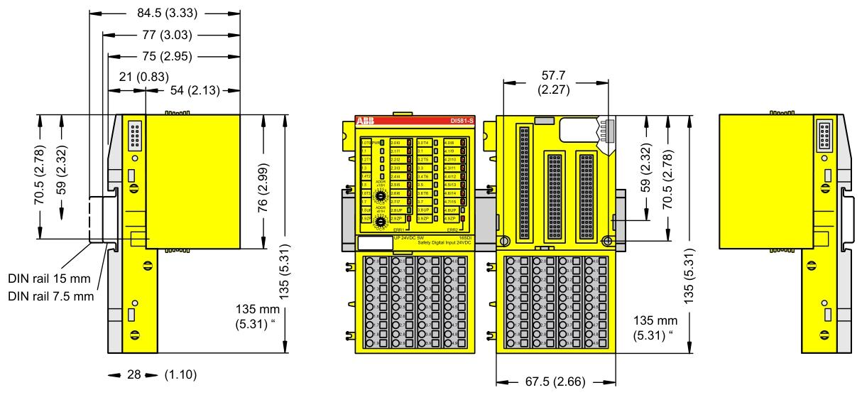
Mechanical Installation
Installed with 35mm DIN rails (7.5mm or 15mm depth), the tightening torque meets the requirements (such as DI581-S with 1.2 Nm) to avoid loosening and poor contact.
The module protection level is mostly IP20 and needs to be installed in a closed control cabinet to prevent direct contact with dust and liquids.
Precautions for Electrical Connections
Power Supply and Voltage
The power supply must comply with PELV/SELV specifications (such as DI581-S 24V DC power supply fluctuation range -15%~+20%, ripple ≤ 5%), avoid overvoltage (such as DI581-S can withstand up to 30V DC) or reverse connection (most modules have reverse connection protection, but caution is still needed).
When configuring redundant power supplies, ensure that the switching time between the two power supplies is less than 10ms (in accordance with EN 61131-2) to avoid module restarts or data loss.
Wiring specifications
Signal cables and power cables should be wired separately with a spacing of ≥ 10cm. The shielding layer should be grounded at one end to reduce electromagnetic interference (such as the RS-232/485 communication line of CI853, which needs to be shielded).
The terminal wiring of digital input/output modules (such as DI581-S) needs to distinguish between positive and negative signals (UP/ZP) to avoid short circuits (although the module has short circuit protection, it may affect other channels).
Configuration and operation precautions
Software configuration
Use official tools such as Control Builder and Automation Builder to configure and ensure firmware version is compatible with the module (e.g. AC500 CPU firmware updates need to be done through an SD card or tool to avoid firmware damage caused by power outages).
Redundancy configuration (such as module redundancy in CI853) requires enabling corresponding parameters, verifying the normal switching function before putting it into operation.
Protocol and Communication
The communication module (such as CI853 supporting MODBUS RTU, COMLI) needs to match the protocol parameters of the slave device (baud rate, parity check, etc.), and the DriveBus of CI858 needs to pay attention to the bus topology (multiple drives require NDBU branch units).
Hot plugging operations are only performed when the module is supported (such as CI853, CI858). Before plugging, ensure that there are no data transmission peaks to avoid communication interruptions.
Safety and maintenance precautions
Special requirements for security modules
The safety input module (such as DI581-S) needs to perform regular self checks (such as program flow control, RAM/CPU diagnostics) to ensure compliance with SIL certification requirements and prohibit bypassing safety function configurations.
Extreme environment modules (such as DI581-S-XC) need to be derated when the temperature is greater than 60 ° C (such as when the number of activated input channels is ≤ 50%) to avoid overheating damage.
Battery and data backup
CPU modules with batteries (such as AC500) need to be regularly checked for battery level (through function blocks or tools). When the battery level is ≤ 20%, they should be replaced in a timely manner. During replacement, the module should be powered to prevent loss of retention data.
Important data (such as the retain variable) is recommended to be backed up regularly through an SD card (using the pms_ram_deport function block for AC500 v3) to avoid data loss caused by battery failure.
Fault handling
When the module reports an error, priority should be given to checking the LED indicator lights (such as the channel LED of DI581-S and the fault LED of CI853), and troubleshooting wiring, power, or configuration issues should be carried out in conjunction with the manual. Blindly replacing the module is prohibited.
When modules involving safety circuits (such as DI581-S) fail, they need to be shut down according to safety procedures, and after troubleshooting, they can be reset using tools. Forced operation is prohibited.
Terminals for channels I0 to I7: 2.0 .. 2.7; Terminals for channels I8 to I15: 4.0 4.7.
All input reference potential terminals (negative pole of process power supply voltage, signal name ZP): 1.9… 4.9.
Electrical isolation from other parts of the module (I/O bus): available.
Input signal indication: Each channel has a yellow LED, and when the input signal is high (signal 1), the LED lights up.
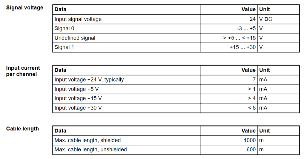
Signal voltage
Input signal voltage: 24 V DC.
Signal 0: -3 .. +5 V。
Undefined signal:>+5 .. < +15 V。
Signal 1:+15 .. +30 V。
Input current per channel
When the input voltage is+24 V: typical 7 mA.
When the input voltage is+5 V:>1 mA.
When the input voltage is+15 V:>4 mA.
When the input voltage is+30 V:<8 mA.
Installation and environmental precautions
Environmental adaptation
Ensure that the working environment of the module meets the parameter requirements: temperature (e.g. DI581-S conventional type is 0~+60 ° C, extreme type DI581-S-XC is -40~+70 ° C), humidity (maximum 95% non condensing), altitude (most modules<2000m), avoid corrosive gases, severe vibrations (in accordance with EN 61131-2 standard), and strong electromagnetic interference.
When installing some modules vertically (such as DI581-S), they need to be downgraded (with a maximum temperature of+40 ° C) to ensure that natural convection cooling is not hindered by cable trays or other components.
Mechanical Installation
Installed with 35mm DIN rails (7.5mm or 15mm depth), the tightening torque meets the requirements (such as DI581-S with 1.2 Nm) to avoid loosening and poor contact.
The module protection level is mostly IP20 and needs to be installed in a closed control cabinet to prevent direct contact with dust and liquids.
Precautions for Electrical Connections
Power Supply and Voltage
The power supply must comply with PELV/SELV specifications (such as DI581-S 24V DC power supply fluctuation range -15%~+20%, ripple ≤ 5%), avoid overvoltage (such as DI581-S can withstand up to 30V DC) or reverse connection (most modules have reverse connection protection, but caution is still needed).
When configuring redundant power supplies, ensure that the switching time between the two power supplies is less than 10ms (in accordance with EN 61131-2) to avoid module restarts or data loss.
Wiring specifications
Signal cables and power cables should be wired separately with a spacing of ≥ 10cm. The shielding layer should be grounded at one end to reduce electromagnetic interference (such as the RS-232/485 communication line of CI853, which needs to be shielded).
The terminal wiring of digital input/output modules (such as DI581-S) needs to distinguish between positive and negative signals (UP/ZP) to avoid short circuits (although the module has short circuit protection, it may affect other channels).
Configuration and operation precautions
Software configuration
Use official tools such as Control Builder and Automation Builder to configure and ensure firmware version is compatible with the module (e.g. AC500 CPU firmware updates need to be done through an SD card or tool to avoid firmware damage caused by power outages).
Redundancy configuration (such as module redundancy in CI853) requires enabling corresponding parameters, verifying the normal switching function before putting it into operation.
Protocol and Communication
The communication module (such as CI853 supporting MODBUS RTU, COMLI) needs to match the protocol parameters of the slave device (baud rate, parity check, etc.), and the DriveBus of CI858 needs to pay attention to the bus topology (multiple drives require NDBU branch units).
Hot plugging operations are only performed when the module is supported (such as CI853, CI858). Before plugging, ensure that there are no data transmission peaks to avoid communication interruptions.
Safety and maintenance precautions
Special requirements for security modules
The safety input module (such as DI581-S) needs to perform regular self checks (such as program flow control, RAM/CPU diagnostics) to ensure compliance with SIL certification requirements and prohibit bypassing safety function configurations.
Extreme environment modules (such as DI581-S-XC) need to be derated when the temperature is greater than 60 ° C (such as when the number of activated input channels is ≤ 50%) to avoid overheating damage.
Battery and data backup
CPU modules with batteries (such as AC500) need to be regularly checked for battery level (through function blocks or tools). When the battery level is ≤ 20%, they should be replaced in a timely manner. During replacement, the module should be powered to prevent loss of retention data.
Important data (such as the retain variable) is recommended to be backed up regularly through an SD card (using the pms_ram_deport function block for AC500 v3) to avoid data loss caused by battery failure.
Fault handling
When the module reports an error, priority should be given to checking the LED indicator lights (such as the channel LED of DI581-S and the fault LED of CI853), and troubleshooting wiring, power, or configuration issues should be carried out in conjunction with the manual. Blindly replacing the module is prohibited.
When modules involving safety circuits (such as DI581-S) fail, they need to be shut down according to safety procedures, and after troubleshooting, they can be reset using tools. Forced operation is prohibited.