Module core information and functional differences
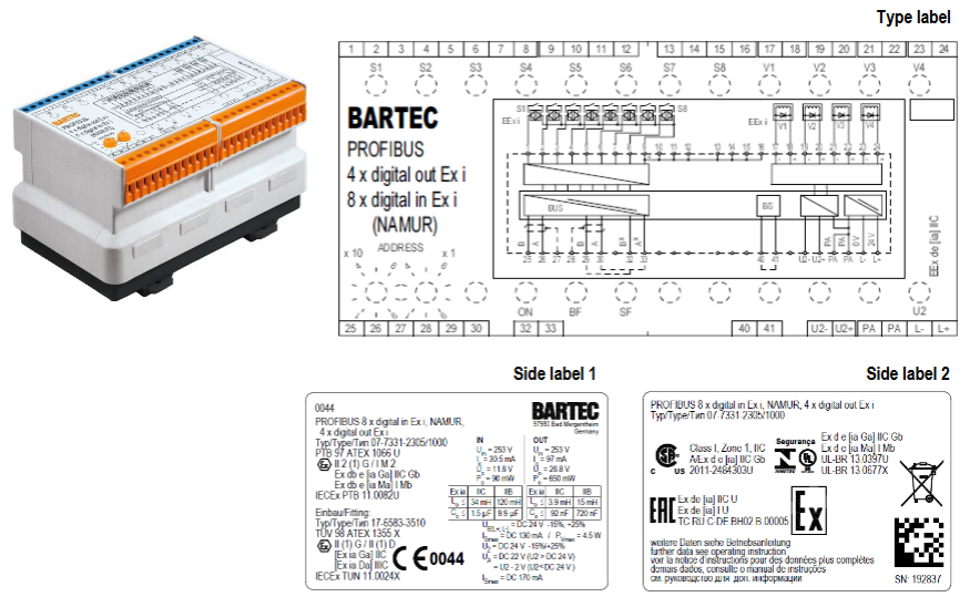
Both modules are PROFIBUS-DP interface devices with “4-channel digital output+8-channel digital input”. The core difference lies in the explosion-proof level of the output terminal. The specific comparison is as follows:
Comparison item model 07-7331-2305/000 model 07-7331-2305/1000
Output explosion-proof level Ex e (increased safety type) Ex i (intrinsic safety type)
Output voltage U2-0.2V (approximately 23.8V when U2 is 24V) DC 22V (when U2 ≥ 24V)
Single channel maximum output current 500mA-
Single channel internal resistance -301 Ω
Module loss power maximum 3.5W maximum 4.5W
Control object: 4-channel Ex e valve, 4-channel Ex i valve
Common core functions:
Input function: 8-channel Ex i intrinsic safety input, supporting NAMUR limit switches, mechanical contacts (compliant with EN/IEC 60947-5-6 standard), with wire breakage/short circuit detection;
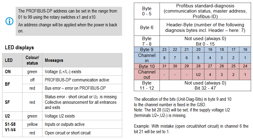
Display function: Real time display of power supply (ON light), bus communication (BF light), status fault (SF light), output power supply (U2 light), and activation/fault status of each channel through LED;
Safety design: Short circuit protection (automatically cuts off output in case of short circuit), reverse polarity protection, supports cutting off actuator power through U2 terminal external emergency stop switch;
Communication and diagnosis: Connected to the control system through PROFIBUS-DP, it can transmit user data and diagnostic data (output disconnection/short circuit status), supporting SYNC (output status freeze) and FREEZE (input status freeze) functions.
Explosion proof certification and compliance
The module is designed for explosive hazardous environments and has passed multiple international certifications to meet compliance requirements in different regions
Certification System Certification Number/Directive Explosion proof Identification/Key Requirements
ATEX PTB 97 ATEX 1066 U, T Ü V 98 ATEX 1355 X II 2 (1) G Ex db e [ia Ga] IIC Gb; I M2 Ex db e [ia Ma] I Mb
IECEx PTB 11.0082U、TUN 11.0024X Ex db e [ia Ga] IIC Gb; Ex db e [ia Ma] I Mb
Regional Compliance CSA(2011-2484303U)、INMETRO(UL-BR 13.0397U)、EAC(RU C-DE.BH02.B.00005) CSA Identification: A/Ex d e [ia] IIC Gb
EU directives ATEX 2014/34/EU, RoHS 2011/65/EU, EMC 2014/30/EU comply with EN 60079 series explosion-proof standards and EN 60529 protection standards
Special explosion-proof requirements:
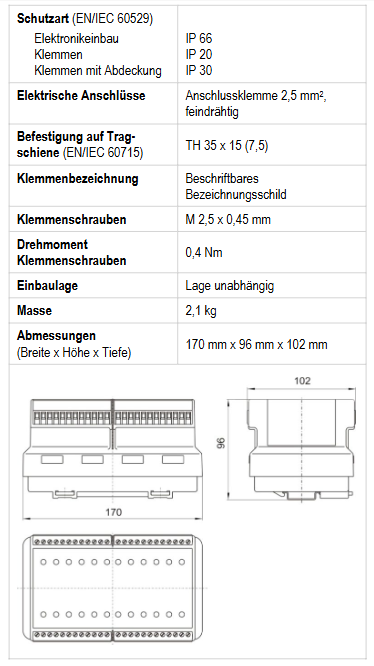
The module is marked with a “U” symbol and needs to be installed in an enclosure that complies with EN/IEC 60079-0 standard and has a protection level of not less than IP54;
If the shell is of Ex e increased safety type, it must meet the electrical clearance and creepage distance specified in Table 1+2 of IEC/EN 60079-7.
Key technical parameters
1. Electrical parameters (general)
Power supply voltage: Electronic part (L+/L -) DC 24V (20-30V); Output section (U2+/U2-) DC 24V (20-30V, supports emergency stop);
Input parameters (Ex i): U ₀=11.8V, I ₀=31mA, P ₀=90mW, linear characteristics, external inductance/capacitance limits vary with explosion-proof level (e.g. Ex ia IIC, L ₀ maximum 47mH, C ₀ maximum 1.5 μ F);
Bus interface: RS485 (screw terminal), PROFIBUS-DP address set through rotary switch (01-99, effective after power failure);
Isolation design: Galvanic isolation is used between power supply, bus, circuit, output, and input.
Grounding requirements: 1-2 grounding terminals should be installed on the right side of the module, and the PA terminal should be connected to the grounding terminal with a 2.5mm ² wire.
Installation and operation specifications
1. Installation requirements
Installation personnel: must have the qualification to install electrical equipment in explosive hazardous areas and have read and understood the instructions;
Preprocessing: Before installation, check that the module is clean and undamaged, there is a power outage, and adjacent live parts are protected;
Operation steps: Insert the module into the guide rail until the buckle makes a sound, and tighten the terminal screws with a torque wrench at 0.4-0.7Nm.
2. Debugging and troubleshooting
Pre debugging inspection: installation correctness, shell integrity, wiring compliance, address and baud rate settings;
Priority for troubleshooting: LED status (such as BF red light indicating bus fault, SF red light indicating short circuit or U2 power failure) → Wiring/terminal fastening → Address/baud rate → Bus terminal and jumper → System restart (required after address change).
3. Maintenance and disposal
Maintenance: No maintenance is required under normal use, and regular inspections by electricians are required according to EN/IEC 60079-17/19;
Repair: Self repair is prohibited, please contact BARTEC GmbH;
Disposal: Belonging to B2B equipment under the WEEE directive, it needs to be disposed of in accordance with local regulations and can be returned to BARTEC (with shipping costs borne by the sender), WEEE number DE 95940350.
Functional positioning: The 1794 series module is a FLEX I/O digital input module used for collecting digital signals (such as sensor and switch status) in industrial automation systems. It is transmitted through Flexbus in conjunction with terminal bases and supports 2-wire/3-wire input devices. Different models correspond to different input channel numbers (8/16/32 channels).
Hardware composition: The module needs to be installed on the 1794 series terminal base (such as 1794-TB3, 1794-TB32, etc.), and the core components include Flexbus connectors (for communication with adjacent bases/adapters), locking mechanisms (fixed modules), key switches (for base configuration), and status indicator lights (yellow, corresponding to the signal status of each input channel).
(2) Preparation before installation
Compatibility confirmation: It is necessary to use a specified communication adapter to ensure normal functionality. For example, 1794-IB32/IB32K requires the use of Remote I/O 1794-ASB (E series and above), ControlNet 1794-ACN15 (C series, firmware 4.1 and above), etc; Programming requires the use of Studio 5000 Logix Designer V20 or higher versions.
Tools and materials: Prepare suitable screwdrivers (for fixing terminal base screws), anti-static tools (grounding wristbands, anti-static cloth), wires that meet specifications (referring to terminal base requirements, usually 22-14 AWG shielded copper wire), DIN rails (made of galvanized chromate passivated steel material to ensure good grounding and avoid poor conductors such as aluminum/plastic).
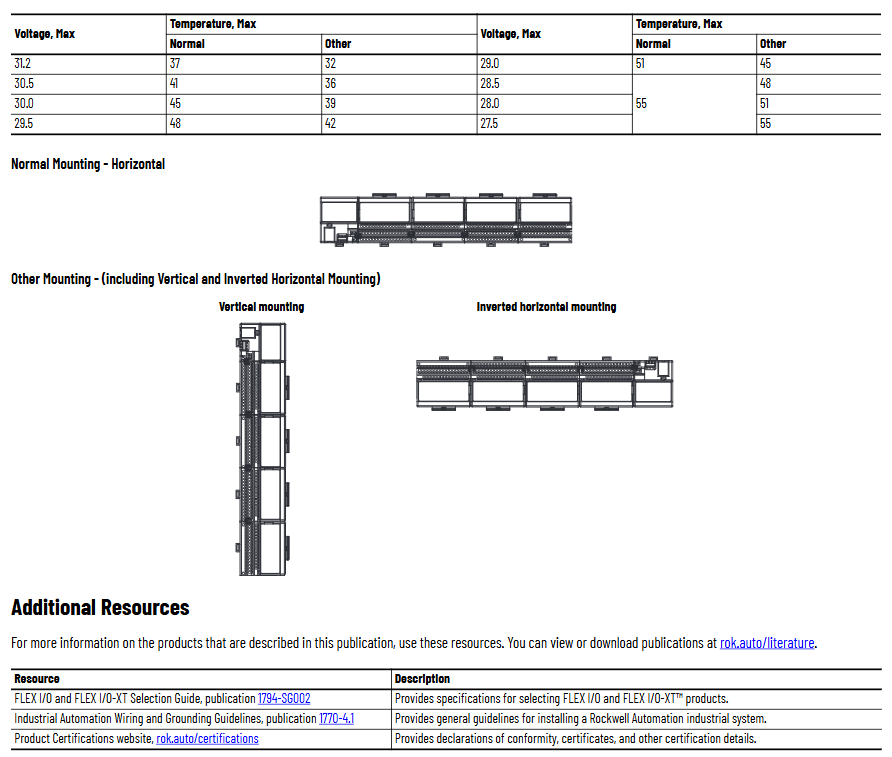
Environmental inspection: Confirm that the installation environment meets the requirements – pollution level 2 (industrial environment), overvoltage category II (EN/IEC 60664-1), altitude ≤ 2000 meters (no need to reduce capacity), and working temperature matching model (IB8/IB16 is -20~+55 ℃, IB32/IB32K is 0~+55 ℃).
Installation and wiring steps
(1) Module installation process
Base configuration: Rotate the key switch (position 3) on the terminal base to the “2” position (corresponding to the module type), ensuring that the Flexbus connector is fully pushed to the left and properly docked with the adjacent base/adapter.
Module alignment: Check if the pins at the bottom of the module are straight, align the alignment rod (position 6) of the module with the groove of the base (position 5), press the module evenly until the locking mechanism (position 2) clicks into the base, and confirm that the module is securely attached to the base.
Cleaning and inspection: During installation, avoid metal debris and wire residue from falling into the module to prevent short circuit damage after power on; After installation, check if all connections are secure and if the pins are not bent.
(2) Wiring method by model
1. 1794-IB8/IB16 (with 1794-TB3/TB3S base)
Wiring steps and operation details
Connect the signal line of the input device to the corresponding terminal of “A row (0-15)” (e.g. Input 0 is connected to A-0, Input 1 is connected to A-1)
Connect the+V DC power cord of the input device to the corresponding terminal of “C row (34-51)” (such as Input 0 connected to C-35), and all+V terminals in C row are internally connected; Connect the DC common terminal (3-wire device) to the corresponding terminal of “B row (16-33)” (such as Input 0 connected to B-17), and the B row common terminal is internally connected
Main power connection+V DC connection C-34, DC common terminal B-16
If the daisy chain extension needs to supply power to the next base, use jumper wires to connect the current base C-51 (+V) to the next base C-34, and B-33 (common terminal) to the next base B-16
2. 1794-IB32/IB32K (with 1794-TB32/TB32S base)
The module is divided into two sets of inputs (0-15, 16-31) and requires independent wiring:
Input 0-15: Connect the signal line to “A row (0-15)”,+V1 to C row 35/37/39/41, COM1 to C row 36/38/40/42;
Input 16-31: Connect the signal line to “B row (17-32, skip 16/33)”,+V2 to C row 43/45/47/49, COM2 to C row 44/46/48/50;
When expanding,+V1 jumps to the next base power terminal through C-41, and COM1 jumps to C-42; +V2 jumps through C-49, COM2 jumps through C-50.
(3) Wiring precautions
2-wire devices only need to connect the signal line and power line, while 3-wire devices require an additional connection to the common terminal;
The insulation layer of the wire needs to be stripped to a suitable length (to avoid short circuits caused by excessive exposure), and the torque of the terminal screws needs to meet the requirements of the base (usually 0.6-0.8 Nm);
Grounding needs to be achieved through DIN rails, which are fixed every 200 millimeters. End anchors need to be installed at both ends to ensure continuous grounding and low impedance.
Module configuration method
(1) Core configuration parameters
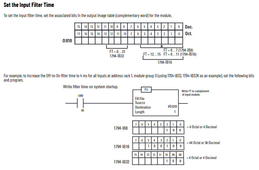
The module sets the input filtering time through the “configuration word (handwriting)”, and the memory mapping and filtering control bits are different for different models. The core adjusts the signal stability through the “input filtering time (FT)” to avoid interference and false triggering.
(2) Filter time setting
Filter time options: selected through 3 binary bits (FT0-FT2), default 0.25 ms, optional 0.5 ms, 1 ms, 2 ms, 4 ms, 8 ms, 16 ms, 32 ms (see Table 6 for specific correspondence).
Configuration position by model:
1794-IB8: The filtering control bit corresponds to the 0-2 bits of “Write 1” and controls all 8 input channels;
1794-IB16: Control Input 0-11 with 0-2 bits, Input 12-15 with 3-5 bits, and support counter function (Input 15 can be set as fast input/standard input, and needs to be configured through CF/CR bits);
1794-IB32/IB32K: The filtering control bit corresponds to bits 8-10 of “Write 1” and controls all 32 input channels.
Configuration example: If you need to set the filtering time of 1794-IB8 to 4 ms, you need to write binary “101” (corresponding to decimal 5) to the “Write 1” address at system startup to ensure that the filtering parameters take effect after the module is powered on.
Technical specifications and certification
(1) Core electrical specifications
Model Number of input channels Rated voltage Conducting current (typical) Turning off current (maximum) Isolation voltage Maximum power consumption
1794-IB8 8 (sinking type) 24V DC 8 mA 1.5 mA 50V DC (850V DC test for 60s) 3.5 W
1794-IB16 16 (sinking type) 24V DC 8 mA 1.5 mA 50V DC (707V DC test for 60s) 6.1 W
1794-IB32 32 (sinking type) 24V DC 4.1 mA 1.5 mA 50V DC (2121V DC test for 2s) 6.0 W
1794-IB32K 32 (sinking type) 24V DC 4.1 mA 1.5 mA 50V DC (2121V DC test for 2s) 6.0 W
(2) Environmental and mechanical specifications
Environmental parameters: working humidity of 5% -95% (no condensation), storage temperature of -40~+85 ℃, vibration (working) of 5 g @ 10-500 Hz (IEC 60068-2-6), impact (working) of 30 g (IEC 60068-2-27);
Mechanical parameters: Module size (with base) 94 × 94 × 69 mm (3.7 × 3.7 × 2.7 inches), weight 71-79 g, no shell (open type), relying on external shell protection.
(3) Compliance certification
The module has passed multiple international certifications to ensure compliant use worldwide, with core certifications including:
Safety certification: UL (Industrial Control Equipment, Class I Division 2 Hazardous Areas, USA/Canada), CSA, TUV (IB16 supports SIL 2 functional safety);
Electromagnetic compatibility (EMC): EN 61326-1, IEC 61000-6-2/4, in compliance with anti-interference and radiation requirements for industrial environments;
Dangerous Place Certification: ATEX (European Zone 2), IECEx (International Zone 2), UKEX (UK Zone 2);
Environmental certification: Compliant with the EU RoHS Directive (2011/65/EU) and China CCC Explosion proof Certification (CNCA-C23-01).
Product core positioning and application scenarios
(1) Positioning
PCI5565 is a high-performance MIL-STD-1553 interface card based on the PCI bus, designed to meet the MIL-STD-1553A/B standard (military data bus standard, used for reliable transmission of critical data in aviation electronics, spacecraft and other systems), supporting multi-channel and multi role 1553 bus communication (bus controller BC, remote terminal RT, bus monitor BM), with high stability and flexible scalability, suitable for scenarios with strict requirements for data transmission security and real-time performance.
(2) Typical applications
Avionics system: data exchange between avionics equipment of fighter jets and passenger planes (such as engine parameters, navigation information, and flight control system command transmission).
Space system: Communication of onboard equipment for satellites and spacecraft, data acquisition and command issuance for ground testing and control platforms.
Military ground equipment: internal and external data bus connections for radar systems, command and control systems, and weapon equipment testing platforms.
High reliability industrial control: Some industrial automation systems that require extremely high fault tolerance and anti-interference capabilities (such as key control modules in the energy and transportation fields).
Core functional characteristics
(1) 1553 bus communication capability
Multi channel and multi role support
Provide 2 independent 1553 channels, each channel can be flexibly configured as a bus controller (BC), remote terminal (RT), or bus monitor (BM) role, and each channel role can be independently set to meet the communication needs of multiple nodes in complex systems.
Supports multiple role combinations such as “BC+RT”, “Dual RT”, “BC+BM”, etc. A single channel can simultaneously achieve BM function (monitoring bus data) and BC/RT function (participating in data transmission).
Protocol and Data Processing
Fully compatible with MIL-STD-1553A/B standard, supporting all standard 1553 message formats (such as standardized transmission of command words, data words, status words), including special communication scenarios such as broadcast messages and mode code instructions.
Built in hardware level message processing engine, capable of automatically encoding/decoding 1553 messages, error detection (such as parity errors, format errors, bit errors) and correction, reducing CPU usage and ensuring real-time performance (message processing latency as low as microseconds).
Support message priority configuration, which can set high priority for critical data (such as emergency control instructions) to ensure their priority transmission.
(2) PCI bus interface characteristics
Compatible with PCI 2.2 standard, supports 32-bit data bus width, operates at a frequency of 33MHz, conforms to the interrupt request (IRQ) mechanism of PCI local bus specification, and is compatible with mainstream x86 architecture and embedded PCI motherboards.
Supports Plug and Play (PnP) functionality, which can automatically recognize hardware parameters (such as base address and interrupt number) through the system BIOS or driver program, simplifying the installation and configuration process.
(3) Hardware Enhancement and Reliability Design
Anti interference and fault tolerance capability
The 1553 bus interface adopts optocoupler isolation design (isolation voltage ≥ 2500Vrms), effectively suppressing electromagnetic interference (EMI) and radio frequency interference (RFI), reducing the impact of external noise on bus communication, and meeting military grade electromagnetic compatibility (EMC) requirements.
Built in bus fault detection and protection mechanism. When a bus short circuit, overload or abnormal signal is detected, the local circuit protection interface card and external bus devices can be automatically cut off. After the fault is restored, communication can be automatically restarted.
Storage and caching
Each 1553 channel is equipped with an independent message cache area (with a typical capacity of 64KB or higher), supporting pre storage and post reading of messages to avoid data loss caused by CPU response delay, especially suitable for high-throughput communication scenarios.
Support non-volatile storage (such as EEPROM), which can save user configuration parameters (such as channel roles, message formats, interrupt triggering conditions). The parameters will not be lost after the system is powered off and will be automatically loaded after restart.
(4) Software Support and Tools
Provide a complete driver package that supports Windows (XP/7/10), Linux (mainstream distribution), and VxWorks (embedded real-time operating system). The driver interface is compatible with industry standard APIs (such as GE specific API and MIL-STD-1553 universal programming interface), making it easy for users to quickly develop applications.
The supporting bus monitoring and configuration tool can display the real-time status of 1553 bus data transmission (such as message content, transmission rate, error statistics), support visual setting and saving of configuration parameters, and provide data logging function for system debugging and troubleshooting.
Detailed technical specifications
(1) Electrical specifications
Category parameter details
1553 bus parameters Bus type: MIL-STD-1553A/B, differential Manchester code
Data rate: 1Mbps (standard rate)
Bus load: Each channel supports up to 31 remote terminals (RTs)
Interface isolation: Optocoupler isolation, isolation voltage 2500Vrms (minimum)
Interface connector 1553 bus: 2 DB-9 or Micro-D connectors (compliant with military connector specifications, optional gold-plated contacts)
PCI Bus: Standard PCI Gold Finger (32-bit)
Weight approximately 100g~150g (depending on specific configuration)
(4) Compliance and Certification
Compliant with military specifications such as MIL-STD-1553A/B (Military Data Bus Standard), MIL-STD-883H (Microcircuit Testing Standard), MIL-STD-461F (Electromagnetic Compatibility Standard), etc.
Through industrial level certification (such as CE, FCC), some models can provide special certification in the aerospace field (such as DO-160G, Aircraft Electronic Equipment Environmental Conditions and Testing Procedures).
Key points for hardware installation and configuration
(1) Installation requirements
Physical installation: The interface card needs to be inserted into a compatible PCI slot (32-bit, 33MHz), ensuring good contact between the gold finger and the slot, and tightening the fixing screws to prevent loosening caused by vibration.
Bus connection: The 1553 bus interface is connected to external 1553 devices through dedicated cables (such as twisted pair cables and shielded wires). Attention should be paid to the configuration of terminal resistors (50 Ω terminal resistors need to be connected at both ends of the bus, and there is no need to configure intermediate nodes) to avoid signal reflection.
Power requirements: Ensure that the motherboard PCI slot provides stable+3.3V and+5V power supply, with a maximum power consumption of no more than 5W, to avoid equipment failure caused by insufficient power supply.
(2) Configuration process
Driver installation: Install the matching driver program in the target operating system (such as Windows, Linux), and confirm that the hardware recognition is normal (no yellow exclamation mark) through the device manager.
Parameter configuration: Use supporting software tools to set 1553 channel roles (BC/RT/BM), message formats (data length, priority), interrupt triggering conditions (such as message reception completion, triggering interrupts during error detection), and other parameters, and save them to non-volatile storage.
Test verification: Send test messages through software tools, monitor the status of bus data transmission, check for errors (such as parity check errors, timeout errors), confirm communication is normal before connecting to the actual system.
Product advantages and competitive highlights
Multi channel high flexibility: Two independent 1553 channels support full role configuration, which can meet the communication needs of multiple nodes and tasks in complex systems without the need for additional interface cards.
Military grade reliability: wide temperature design (-40 ℃~+85 ℃), optocoupler isolation, EMC anti-interference ability, and fault protection mechanism ensure stable operation in harsh environments (such as high temperature, vibration, strong electromagnetic interference), meeting the strict requirements of military equipment.
Low CPU usage: The hardware level message processing engine reduces software intervention, lowers host CPU load, and ensures system real-time performance, especially suitable for embedded real-time operating system (such as VxWorks) environments.
Wide compatibility: compatible with mainstream operating systems and PCI motherboards, with accompanying software tools to simplify development and debugging, and reduce user application barriers.
The installation instructions for the redundant modules of the Rockwell Automation 1757-SRM series B-type ProcessLogix and ControlLogix systems are designed to guide users in installing the redundant module into the ProcessLogix or ControlLogix redundant chassis, covering the entire process of installation preparation, operation steps, fault handling, technical specifications, and more.
Important User Information and Security Standards
(1) Definition of Core Security Warning
The document specifies the meanings of different security signs to avoid operational risks, as follows:
Meaning of identification
Warning: Operating scenarios in hazardous environments that may cause explosions, resulting in personal injury, property damage, or economic loss
IMPORTANT annotation is crucial for the successful application and understanding of product information
Attention: Identify operational methods that may result in personal injury, property damage, or economic loss, and explain how to identify and avoid hazards and consequences
Labels on or inside SHOCK HAZARD equipment (such as drivers, motors) warning of hazardous voltage
Labels on or inside BURN HAZARD equipment (such as drives, motors) warning that the surface may reach dangerous temperatures
(2) Special environmental usage requirements
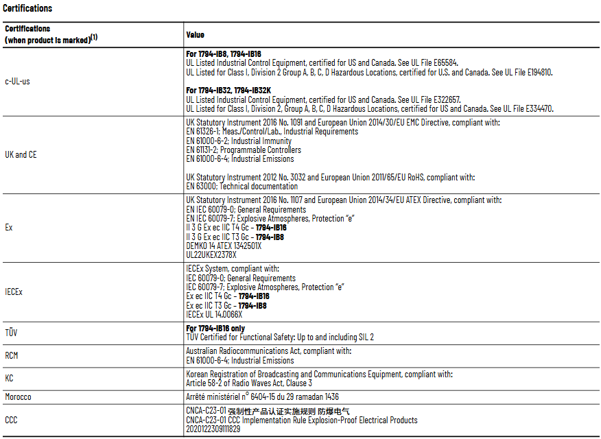
North American Hazardous Area Certification: Products marked as “CL I, DIV 2, GP A, B, C, D” are only applicable to Class I, Division 2, Groups A, B, C, D hazardous areas and non hazardous areas; When the system is used in combination, the overall temperature level must be determined by the temperature code with the lowest “T” number, and the equipment combination must be inspected by the local competent department.
European Hazardous Place Certification: Products marked with EEx comply with EU Directive 94/9/EC, are suitable for potentially explosive environments, must be installed in enclosures that meet at least IP54 protection level (Class I, Zone 2 environment), and can only be used in conjunction with ATEX certified backplates; At the same time, the device is not resistant to sunlight and other ultraviolet radiation, and transient interference should be prevented from exceeding the rated voltage by more than 40% in Class I Zone 2 environment.
General environmental requirements: Suitable for industrial environments with pollution level 2, overvoltage category II applications (compliant with IEC 60664-1), with no need for derating at altitudes up to 2000 meters (6561 feet); Belonging to Group A industrial equipment under the IEC/CISPR 11 standard, if appropriate protective measures are not taken, conducted and radiated interference may affect electromagnetic compatibility; The device is of an open design and needs to be installed in an enclosure that meets specific environmental requirements. The enclosure must have flame retardancy (non-metallic enclosures must reach 5VA, V2, V1, V0 or equivalent flame retardant levels), and the interior must be accessible with tools.
Module basic information and installation preparation
(1) Module core functions and appearance
Functional positioning: The 1757-SRM (B series) module is used for redundant control of ProcessLogix and ControlLogix systems, achieving communication and status synchronization between the primary and backup chassis through fiber optic connections, ensuring smooth switching in case of system failures.
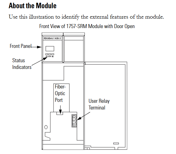
Appearance structure: The front includes status indicator lights, fiber optic ports, and user relay terminals. These components are required to achieve module status monitoring, fiber optic connections, and external device control (such as relay linkage).
(2) Preparation before installation
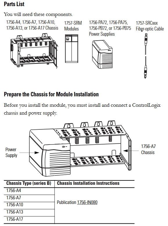
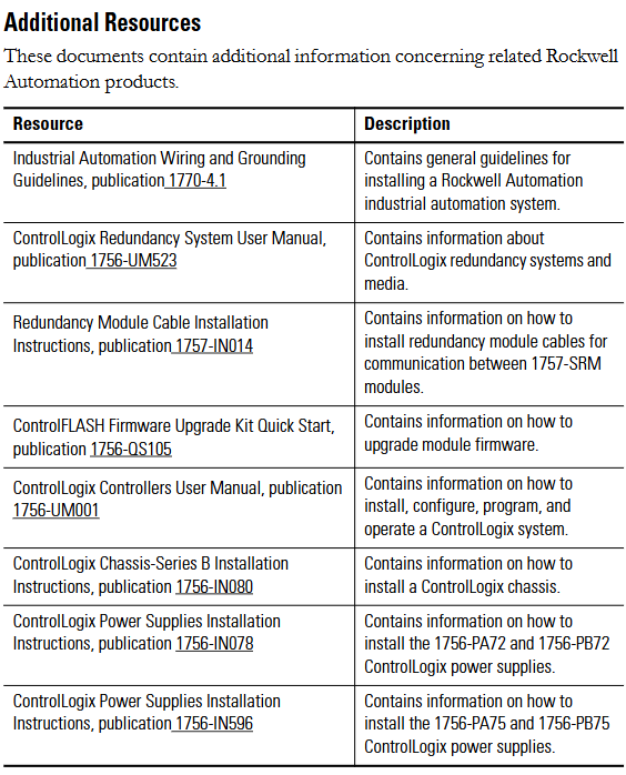
Component List: Prepare 1756-A4/A7/A10/A13/A17 series chassis, 1757-SRM module, 1756-PA72/PA75/PB72/PB75 series power supply, and 1757-SRCxxx series fiber optic cable.
Static electricity protection: The module is sensitive to static electricity. Before operation, it is necessary to touch a grounded object to release static electricity and wear a certified grounding wristband to avoid touching the connectors/pins and internal circuit components of the component board. When idle, it should be stored in anti-static packaging and an anti-static workstation should be used when conditions permit.
Chassis and power pre-processing: The ControlLogix chassis and power supply need to be installed and connected first. Different models of chassis (such as 1756-A4/A7, etc.) and power supplies (such as 1756-PA72/C, 1756-PB72/B, etc.) should refer to the corresponding installation instructions (such as 1756-IN080, 1756-IN078, etc.).
Module slot selection: The recommended slot positions for different models of chassis are different. For example, slot 1 or 2 is recommended for the 1756-A4 chassis, and slot 4 or 5 is recommended for the 1756-A7 chassis. It is necessary to strictly install according to the recommended positions to ensure normal communication and redundancy functions.
Redundant system assembly steps
(1) Core installation process
Fiber optic cable connection: Before installing the module, connect one end of the 1757-SRCxxx series fiber optic cable (available in 1m, 3m, 10m, 50m, 100m specifications) to the fiber optic port of the module; If the distance between the main and backup chassis exceeds 100 meters, customized fiber optic cables must be used. The optical loss at a wavelength of 1300nm should be ≤ 7dB, and the length should be ≤ 4 kilometers (2.49 miles). 62.5/125 micron multimode fiber optic cables and professionally installed SC connectors should be used.
Module installation: Install the 1757-SRM module into the corresponding slots on the main and backup chassis (if the main chassis is plugged into slot 5, the backup chassis also needs to be plugged into slot 5); During installation, align the upper and lower rails of the chassis, slide the module in and ensure that the backplane connector is properly connected. When the module is aligned with other installed modules, it indicates that it is installed in place; When disassembling, press the locking clips on the upper right and lower left corners of the module, and then slide the module out.
Relay terminal wiring: If using a user relay, the wire needs to be threaded through the Steward 28A2029-0A0 model ferrite core (the core should be as close as possible to the end of the wire insulation layer), then connected to a detachable terminal block, and finally inserted into the relay terminal; The relay terminals must obtain external DC power from the same line as the SRM chassis power supply and comply with UL Class 2 (North America) or CE SELV/PELV (Europe) standards.
(2) Key operations of system configuration
Firmware upgrade: Data backup is required before upgrading (upgrading will overwrite old data), from the Rockwell Automation support website( http://support.rockwellautomation.com )Download the latest firmware and ControlFLASH firmware upgrade tool; Only supply power to one redundant chassis, wait for the module to display “FACT BOOT FLSH UPDT REQ”, start the upgrade tool to complete firmware installation, and after success, the module displays “PRIM”; Repeat the operation to upgrade another chassis module. If the upgrade is interrupted, the module will display “FACT BOOT FLSH UPDT REQ” or “USER BOOT FLSH UPDT REQ” after restarting the chassis, and a new upgrade is required.
Main chassis specification and system verification:
Main chassis designation: The chassis that is powered on first automatically becomes the main chassis, the module displays “PRIM” and the PRI indicator light turns green, and the normally open contacts of the relay are closed; If both chassis are powered on simultaneously, the chassis containing the module with the smaller serial number becomes the main chassis; The initial display of the backup chassis is “DISQ” or “SYNC”, the PRI indicator light is not on, and the normally open contact of the relay is disconnected.
System verification: After the main and backup chassis are powered on, automatic verification begins to verify the hardware and firmware compatibility of the main and backup modules. If the backup chassis displays “SYNC”, it indicates compatibility between configuration and firmware; If “DISQ” is displayed, it may be due to mismatched chassis configuration, inconsistent firmware versions, different Keeper parameters of ControlNet module, or MAC address not set to the same node address. The problem needs to be investigated and resolved.
Module status monitoring and fault handling
(1) Status indicator lights and display interpretation
Module status display (four characters):
When starting, displaying “Txxx” (xxx is the hexadecimal test number) indicates self-test;
“Indicates a transitional state;
DISQ “indicates that the backup chassis has not passed validation,” SYNC “indicates that the backup chassis has passed validation, and” PRIM “indicates the main chassis;
BOOT, ERAS, and PROG respectively represent boot mode (waiting for instructions), boot mode (erasing firmware), and boot mode (loading new firmware);
‘Exxx’ (xxx is an error/fault code) indicates a major malfunction and will alternately display fault information and error codes.
Health status indicator light:
Extinguished: The module is not powered on;
Always red: module self checks during startup or serious malfunction occurs;
Flashing red: The module is updating NVS, experiencing non critical faults, or configuring incorrectly;
Evergreen: The module is running normally;
Flashing green: The module is running normally but not communicating with other modules.
Inter module communication indicator light:
Extinguish: The module is not powered on or has no communication activity;
Red flash (<1 second): The module has been started and partner communication has been established;
Frequent red: serious communication failure occurs;
Green flash: There is communication activity (sampled every 250 milliseconds).
Chassis status indicator light:
Extinguish: The module is not powered on or the chassis is in standby/fault state;
Green flash (<1 second): Power on, partner module is determining the main state;
Evergreen: The chassis is in the main engine state.
(2) Fault type and handling
Fault classification:
Minor recoverable faults: do not affect redundant operations, modules may clear on their own;
Minor unrecoverable fault: does not affect redundant operations, but has no recovery mechanism;
Serious recoverable faults: affecting redundant operations (possibly not immediate), such as backup module failures that may affect control in the event of a host failure;
Recovery instruction: The module displays “RPLC MOD” and needs to be replaced, “RSET MOD” needs to be reset, “REMV MOD” needs to be removed, and “SEAT MOD” needs to be reinserted.
Technical specifications
(1) Module core parameters
Category parameter values
Backplane current 3.3V DC 0.75A
5.1V dc 1.0A
24V dc 0.160A
Dimensions (height x width x depth) Standard ControlLogix chassis (2 slots wide) 14.5 x 7 x 14 centimeters (5.71 x 2.76 x 5.51 inches)
Weight – Approximately 0.452 kilograms (14.53 ounces)
Shell Protection Level – None (Open)
Temperature code IEC T4
North American T4A
Maximum power consumption -11.28W
Maximum heat dissipation -38.49 BTU/hour
Isolation voltage relay terminal to system for a continuous 30V, basic insulation type (853V AC test for 60 seconds)
(2) Redundant cable parameters
Parameter values
Connector SC type (fiber optic)
Cable type 62.5/125 micron multimode fiber
1 channel (sending and receiving fiber optic)
Wavelength 1300nm
(3) User relay terminal parameters
Parameter values
Power requirement: 11-30V DC; Typical current of 270mA at 24V DC (must comply with UL Class 2 or CE SELV/PELV standards)
Guiding load rated 30V DC Class 2/SELV, 100mA
Wiring category (Port 1) 3
Suitable for solid or stranded shielded copper wires of 0.3-2.1 square millimeters (22-14 AWG), rated temperature ≥ 75 ℃ (167 ℉), with a maximum insulation layer of 1.2 millimeters (3/64 inches)
Working temperature 0-60 ℃ (32-140 ℉) (compliant with IEC 60068-2-1, 60068-2-2, 60068-2-14 standards)
Storage temperature -40-85 ℃ (-40-185 ℉) (compliant with IEC 60068-2-1, 60068-2-2, 60068-2-14 standards)
Relative humidity 5% -95% (non condensing) (in accordance with IEC 60068-2-30 standard)
Vibration (working) 2g @ 10-500Hz (compliant with IEC 60068-2-6 standard)
50g impact (non working) (compliant with IEC 60068-2-27 standard)
Impact (working) 30g (compliant with IEC 60068-2-27 standard)
Radiation emission complies with CISPR 11:1 Group A
Electrostatic immunity: 6kV for contact discharge and 8kV for air discharge (in accordance with IEC 61000-4-2 standard)
(5) Certification qualifications
The module is approved by UL (Industrial Control Equipment, document E65584) and CSA (Process Control Equipment, document LR54689C); Multiple certifications such as LR69960C, FM, CE (compliant with the 2004/108/EC EMC Directive), C-Tick (compliant with the Australian Radio Communications Act), EEx (compliant with the 94/9/EC ATEX Directive), T Ü V (functional safety certification, up to SIL 2), etc. are applicable to compliance requirements in different regions and scenarios.
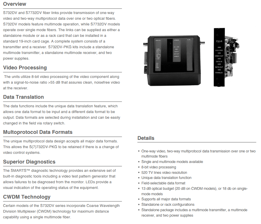
KIDDE S732DVT-EST1 belongs to the S732DV series products, which together with the S7732DV series form a fiber optic link solution. Its core function is to achieve unidirectional video and bidirectional multi protocol data transmission through one to two optical fibers. Among them, the S732DV series is a multimode fiber model, and the S7732DV series is a single-mode fiber model. The product has a flexible form and can provide independent modules or rack cards suitable for standard 19 inch card cages. The complete system needs to include a transmitter and receiver; The S732DV-PKG kit is additionally equipped with an independent multi-mode transmitter, independent multi-mode receiver, and two power supplies.
Core functions and advantages
(1) Video processing
Adopting 8-bit video processing technology with a signal-to-noise ratio greater than 55dB, it can ensure clear and noise free video signals at the receiver end. At the same time, the video resolution reaches 520 TV lines, with a bandwidth of 6.5MHz, supporting both NTSC and PAL video formats. The input/output signal is a 1.0Vpp composite signal, with an input/output impedance of 75 ohms, differential phase less than 3 °, and differential gain less than 3%.
(2) Data transmission
Data conversion function: With unique data conversion features, it can input one data format and output another. During installation, the data format can be selected, and it can also be easily changed on-site by rotating the switch.
Multi protocol compatibility: The multi protocol data design is compatible with all mainstream data formats, and even if the video control system changes, S (7) 732DV-PKG can still be used.
Data parameters: including one full duplex data channel, supporting RS-232 (3-wire/5-wire), TTL, RS-422, RS-485 (2-wire/4-wire), Manchester encoding, biphase encoding, SensorNet, DTMF control and other formats. The baud rate range is 250kbps to 512kbps (depending on the data format), and the bit error rate is lower than 1.0E-9.
(3) Diagnosis and Monitoring
Equipped with SMARTS ™ Diagnostic technology, with built-in rich diagnostic tools, including a video test pattern generator, can diagnose faults through the display; Equipped with LED indicator lights, it can intuitively display the operating status of the equipment, making it convenient for users to grasp the equipment situation in real time.
(4) Special Technology
Some models of the S732DV series integrate coarse wavelength division multiplexing (CWDM) technology, which can achieve maximum transmission distance using a single multimode fiber, improving transmission efficiency and flexibility.
Technical specifications
(1) Optical parameters
Parameter details
Fiber type multimode (MM)
Number of optical fibers: 1
Fiber optic connector type ST
Mode multimode or single-mode (depending on the model)
Multi mode optical budget 13dB (CWDM model is 20dB); Single mode 18dB
The transmitter is multi-mode LED; Single mode laser
Wavelength multimode 850nm or 1300nm; CWDM models 1310nm and 1330nm; single-mode 1310nm or 1550nm (depending on the model)
The maximum transmission distance for multi-mode is 4.0 miles (6.5 kilometers) (RST1L model exceeds 7.5 miles/12 kilometers); Single mode up to 37 miles (60 kilometers) (depending on model)
Multi mode transmission power/reception sensitivity -15dBm; Single mode -10dBm/-28dBm
Gain Control Optical Automatic Gain Control (OAGC)
(2) Electrical parameters
Parameter details
Input power supply (independent unit) 24V AC or 13.5V DC (regulated)
Input power supply (rack unit) 13.5V DC (stabilized)
Current requirement 450mA
Power consumption 6W
Power factor 4 (rack unit only)
Protection against solid-state short circuits
Power supply model 615P-1/EU (order code: 188-3178/EU) or 615P-1/UK (order code: 188-3178/UK)
(3) Physical and environmental parameters
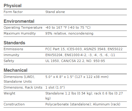
Physical specifications
Form: Independent
Independent unit size (length x width x depth): 5.0 inches x 4.8 inches x 1.5 inches (127 x 122 x 38 millimeters)
Product positioning: FBM217 is a highly compatible and reliable 32 channel discrete input module, suitable for the acquisition of various switch signals (such as sensors, contactor contacts) in industrial sites. It supports single module independent operation or dual module redundant configuration, and is widely used in industries such as petrochemicals, power, and manufacturing that require high signal stability.
Product Core Features
The FBM217 module meets the high requirements of industrial scenarios through hardware design and functional optimization, with the following core features:
Multi channel and wide voltage support:
Provides 32 discrete input channels, with a single channel that can flexibly adapt to multiple signal types: 15-60V DC (low voltage), 120V AC/125V DC (medium voltage), 240V AC (high voltage), compatible with voltage monitoring (requires external power supply) and contact detection (can use module auxiliary power supply) modes.
Support cascading of “main extension” terminal components (TA), which can increase signal access capability by extending TA and adapt to upgrade and replacement scenarios of 100 series FBM modules (such as FBM07A/B, FBM20).
Redundancy and reliability design:
Support single module or dual module redundant configuration: In redundant mode, two FBM217s share a terminal component through a redundant adapter (P0926ZY), doubling the field input current. When the module fails, it automatically switches to the backup module, ensuring uninterrupted signal acquisition.
The redundant logic is implemented by the CINR function block of Foxboro Evo control software, which synchronously reads data from two modules during each execution cycle, selects high-quality signals to participate in control, and enhances the system’s fault tolerance.
Signal processing and protection:
Programmable filtering/debounce time: supports 5 configurations of “no filtering, 4ms, 8ms, 16ms, 32ms”, which can be adjusted according to the on-site interference situation to reduce signal false triggering caused by high-frequency noise.
Terminal assembly (TA) integrated protection function: including high-voltage attenuation circuit, optocoupler isolation, current limiting device, some TAs support channel level or group level isolation (such as P0916PS/PT supporting channel isolation), withstand 600V AC (1 minute) to ground voltage, and avoid signal surge damage to the module.
Convenient maintenance and visualization:
Integrated LED indicator lights on the front panel: display module operating status (such as bus communication, power supply) and discrete status of 32 channels (on/off), intuitively locating faulty channels.
Hot swappable design: Modules can be replaced without disconnecting field wiring, power or communication cables. Under redundant configuration, replacing a single module does not affect field signal input and reduces system downtime.
Functional specification parameters
(1) Input signal and electrical parameters
Parameter category specific specifications
32 channels, group isolation (some TAs support channel isolation)
On State voltage 15-30V DC (low voltage); 80-132V AC/75-150V DC (medium voltage); 164-264V AC (high voltage)
Off State voltage 0-5V DC (low voltage); 0-20V AC/0-20V DC (medium voltage); 0-40V AC (high voltage)
Typical input current 2.2mA (at 30V DC); 1.6mA (maximum value at high voltage)
When the source resistance limits conduction, it is ≤ 1k Ω (15V DC); When turned off, ≥ 100k Ω (30V DC)
Pulse counting capability up to 250Hz, supporting pulse signal acquisition (such as flow meter pulses)
(2) Communication and Power Supply
Communication interface: Connected to the fieldbus communication module (FCM) or control processor (FCP) through a 2Mbps module fieldbus, supporting A/B dual path redundancy, automatically switching to the backup path in case of single path failure, ensuring data transmission continuity.
Power requirements:
Input voltage: 24V DC (in redundant configuration), allowing ± 5% (upper limit) and -10% (lower limit) fluctuations.
Power consumption: maximum 3W (at 24V DC); Thermal Dissection: Maximum 5W (at 24V DC), no additional calibration required.
(3) Isolation and protective performance
Isolation level: The module and terminal assembly (TA) combination has high isolation capability, and the group isolation TA (such as P0916CA, P0924HA) can withstand 600V AC (1 minute) to ground voltage; High voltage TA (such as P0916PY, P0916QB) meets UL dielectric potential requirements, and channel isolation TA (such as P0916PS, P0916PU) further enhances anti-interference ability.
Electromagnetic compatibility (EMC): Complies with the European EMC Directive 2004/108/EC and multiple international standards, as follows:
Radiation emission: EN 50081-2 (industrial environment) CISPR 11 Class A;
Immunity: ESD (contact 4kV/air 8kV), radiation field (10V/m, 80-1000MHz), electrical fast transient (2kV, I/O/power/communication line), surge (2kV AC/DC power line, 1kV I/O/communication line), etc.
Environmental and Physical Specifications
(1) Environmental adaptability
The FBM217 module and terminal assembly (TA) meet the requirements of harsh industrial environments, with specific parameters as follows:
Environmental Category Module (FBM217) Terminal Assembly (TA) – PVC Material Terminal Assembly (TA) – PA Material
Working temperature -20~+70 ℃ (-4~+158 ° F) -20~+50 ℃ (-4~+122 ° F) -20~+70 ℃ (-4~+158 ° F)
Weight: Approximately 284g (10oz), lightweight design facilitates dense installation.
Installation method:
Module: Installed on a DIN rail base plate (supporting 4 or 8 slots), the base plate can be installed horizontally/vertically on a DIN rail, or adapted to a 19 inch rack through an installation kit; Redundant modules need to be installed in odd even positions adjacent to the base plate (such as slots 1-2 and 3-4).
Terminal Assembly (TA): DIN rail mounting, compatible with 32mm (1.26in) and 35mm (1.38in) standard rails, supports compression terminals (24-12 AWG wires) or ring terminal blocks (22-12 AWG wires).
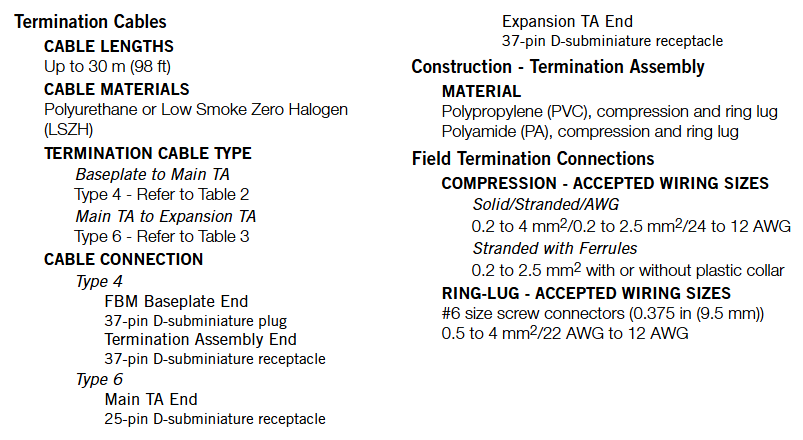
Cable specifications:
Base board to main TA: Use Type 4 cable (37 pin D-sub interface), with a maximum length of 30m (98ft), optional polyurethane (P/PVC), low smoke halogen-free (LSZH) materials, suitable for temperature resistance and environmental protection requirements in different environments;
Main TA to Extended TA: Use Type 6 cable (25 pins on the main TA end and 37 pins on the extended TA end), with a length of 0.75m (2.5ft), only available in LSZH material.
Terminal Assembly (TA) and Compatibility
Terminal assembly (TA) is a key interface between FBM217 and on-site equipment, providing signal conditioning, isolation, and power distribution functions. Different TAs are adapted to different signal scenarios, and the core parameters are as follows:
(1) Classification and adaptation of main terminal assembly (TA)
FBM type input signal type TA model (PVC/PA material) terminal type cable type certification level
FBM217 30V DC Voltage Monitoring (Group Isolation) P0916CA/P0916CB Compression/Ring Lug Type 4 1, 2, 4
FBM217 24V DC contact detection (group isolation) P0916PW/P0916PX (PVC); P0916XZ (PA) Compression/Ring Lug Type 4 1, 2, 4
FBM217 120V AC/125V DC voltage monitoring (channel isolation) P0916PS/P0916PT (PVC); P0916YA (PA) Compression Type 4 1, 4
FBM217 120V AC/125V DC contact detection (group isolation) P0916PY/P0916PZ (PVC); P0916YB (PA) Compression/Ring Lug Type 4 1, 4
FBM217 240V AC Voltage Monitoring (Channel Isolation) P0916PU/P0916PV Compression/Ring Lug Type 4 1
FBM217 240V AC Contact Detection (Group Isolation) P0916QA/P0916QB Compression/Ring Lug Type 4 1
FBM217 replaces FBM07A (15-130V DC voltage monitoring) P0924HA compression type 4 1, 2, 4
FBM217 replaces FBM08 (120V AC/125V DC voltage monitoring) P0924HC compression type 4 1, 4
(2) Expansion Terminal Assembly (TA) adaptation
Expanding TA is used to increase the number of channels and needs to be cascaded with the main TA to adapt to the upgrade of the 100 series extended FBM module. The core models are as follows:
Compatible with 100 series extended FBM input signal specifications, extended TA model (PA material), cable type certification level
FBM12A/B (16 contacts/voltage) with main TA P0924HA P0924HB Type 6 1, 2, 4
FBM13 (16 channel voltage monitoring) with main TA P0924HC P0924HD Type 6 1, 4
FBM21 (16 channel voltage monitoring) with main TA P0924HL P0924HM Type 6 1
FBM25B (16 way contact detection) with main TA P0924HP P0924HS Type 6 1, 2, 4
(3) Certification Level Definition (Table 1)
TA certification strictly follows international safety standards, and different levels correspond to different application scenarios:
Type 1: UL/UL-C certification, suitable for Class I A-D Group 2 hazardous environments (temperature code T4); CENELEC (DEMKO) certification for Zone 2 potentially explosive environments (EEx nA IIC T4).
Type 2: In addition to Type 1, it also meets the requirements of “non flammable on-site circuits” and is compatible with Class 2 limited energy circuits (60V DC/30V AC, ≤ 100VA).
Type 4: All on-site circuits meet Class 2 limited energy requirements and require external equipment to comply with Class 2 restrictions.
Compliance Certification and System Integration
(1) Regulatory Compliance Certification
The FBM217 module and TA have passed multiple international certifications to ensure compliant use in different regions and industries
Electromagnetic compatibility (EMC): Complies with the European EMC Directive 2004/108/EC, meets EN 50081-2 (emission), EN 50082-2 (immunity), EN 61326 (industrial grade) standards, is compatible with CISPR 11 Class A limits, and is resistant to interference such as ESD, radiated fields, and electrical fast transients.
Product safety:
UL/UL-C certification: applicable to Class I A-D Group 2 hazardous environments (T4 temperature code), as an “associated device” supplying power to non flammable circuits;
European Low Voltage Directive (2006/95/EC) and ATEX Directive (94/9/EC): CENELEC (DEMKO) certified, suitable for Zone 2 environments, supplying power to Group IIC non flammable field circuits.
(2) System integration and upgrade
100 series FBM module upgrade: FBM217 can directly replace 100 series discrete input modules (such as FBM07A/B, FBM08, FBM20), and achieve hardware compatibility and functional upgrades by adapting the corresponding TA (such as P0924HA replacing FBM07A), without the need to reconstruct on-site wiring.
Event Sequence (SOE) Integration: Supports SOE functionality for Foxboro Evo v8. x and above software, combined with GPS time synchronization (optional), enabling millisecond level event collection, storage, and reporting across control processors; Versions below v8. x require SOE implementation through ECB6 and EVENT blocks, with a time accuracy of seconds and no cross processor synchronization.
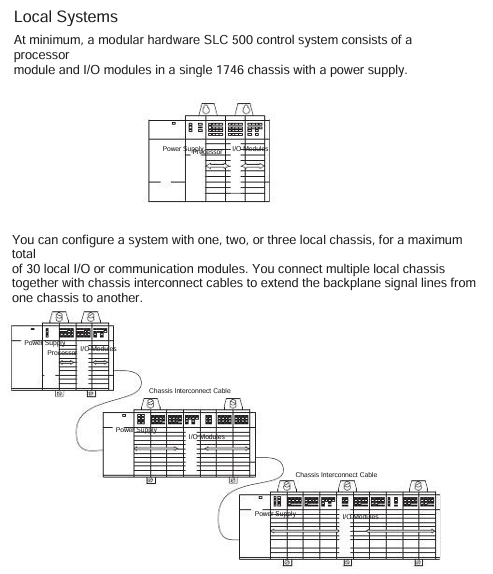
The 1746 I/O system is a modular expansion unit of the SLC 500 programmable logic controller, with core components including:
I/O module: Various functional modules of the 1746 series (such as digital IB/OB series, analog NI/NO series, special function modules) provide signal acquisition and control output functions for the system.
I/O rack (Chassis): includes models such as 1746-A1 (1 slot), 1746-A2 (2 slots), 1746-A7 (7 slots), 1746-A10 (10 slots), etc., used for installing modules and providing backplane buses (data and power transmission). Slot 0 is default for processor modules (such as 1747-L511), and the rest are I/O module slots.
Power modules, such as 1746-P2 (24V DC 2.0A) and 1746-P4 (24V DC 4.0A), provide stable DC power to the rack and modules. The appropriate model should be selected based on the total power consumption of the module.
Communication link: Supports industrial buses such as DH-485, ControlNet, DeviceNet, etc., to achieve data exchange between I/O modules, processors, and upper computers.
(2) System characteristics
Modular design: Modules can be combined as needed, supporting mixed installation of digital, analog, and special functional modules, and flexibly adapting to different industrial scenarios (such as manufacturing production lines and process control).
Backplane bus technology: The rack is equipped with a 16 bit data bus with a transmission rate of 1Mbps, ensuring real-time data exchange between modules. Class 1/3 interface modules can flexibly allocate memory addresses.
Environmental adaptability: The entire series of modules comply with industrial standards, with a working temperature range of 0-60 ℃ (some modules can withstand high temperatures of 60 ℃ in the rightmost slot), humidity of 5% -95% (no condensation), and adaptability to complex environments such as workshops and outdoor control cabinets.
Redundancy and Expansion: Supports multi rack expansion (connected through communication modules), and some key modules (such as power and control modules) can be configured redundantly to improve system reliability.
Module Classification and Core Features
The 1746 series I/O modules are divided into four categories according to their functions, and the core models and characteristics of each category are as follows:
(1) Digital input module
Model Channel Number Input Type Core Characteristics Typical Applications
1746-IB16 16 16 channel 24V DC sinking 4 groups isolated (4 points/group), response time ≤ 3ms, with fuse protection (Series A/B/C) button, limit switch signal acquisition
1746-IB32 32 channel 24V DC sinking 4 groups isolated (8 points/group), low-power design, suitable for high-density signal acquisition pipeline workstation status monitoring
1746-IV16 16 16 channel 24V DC sourcing has the same structure as IB16, with opposite input polarity, and is compatible with PNP type sensor photoelectric sensor signal acquisition
1746-IV32 32 channel 24V DC sourcing 32 channel high-density design, inter group isolation, supports long-term operation in harsh environments, multi state monitoring of large equipment
(2) Digital output module
Model Channel Number Output Type Core Characteristics Typical Applications
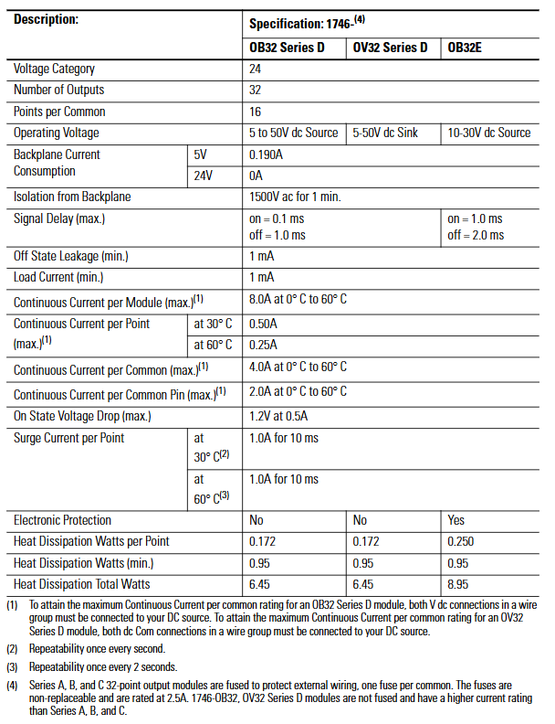
1746-OB16 16 24V DC sourcing 2 groups isolated (8 points/group), single channel maximum current 0.5A, with fuse protection small relay and indicator light control
1746-OB32 32 channel 24V DC sourcing 32 channel high-density, 2 groups isolated (16 points/group), total continuous current 8A multi actuator synchronous control
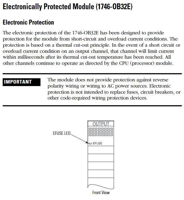
1746-OB32E 32 channel 24V DC sourcing with built-in electronic protection (short circuit, overload thermal cut-off), automatic reset of fault channels, key equipment control (requiring fault self recovery)
1746-OV16 16 channel 24V DC sinking output polarity opposite to OB16, compatible with NPN type actuators, inter group isolation solenoid valves, and small motor control
(3) Analog input module
Model Channel Number Input Signal Core Characteristics Typical Applications
1746-NI4 4-channel voltage (± 10V/0-10V, etc.), current (4-20mA, etc.) successive approximation A/D conversion, accuracy ± 0.1%, automatic temperature compensation pressure, temperature transmitter signal acquisition
1746-NI8 8-channel voltage and current, 8-channel high-density, supports single ended/differential wiring, programmable filtering (8 frequencies), multi parameter process monitoring (such as liquid level, flow rate)
1746-NR4 4-channel RTD (Pt100, Cu100, etc.) dedicated RTD signal conditioning, strong anti-interference ability, accurate ± 0.05% temperature monitoring (such as chemical reaction kettle)
1746-NT4 4-channel thermocouple (J, K, T, etc.) with built-in cold end compensation, supports open circuit detection, and is suitable for temperature acquisition in high-temperature environments such as kilns and heating furnaces
(4) Analog output module
Model Channel Number Output Signal Core Characteristics Typical Applications
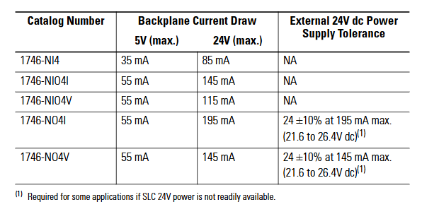
1746-NO4I 4-channel current (4-20mA) D/A conversion accuracy ± 0.1%, output short-circuit protection, inter group isolation valve positioner, frequency converter control
1746-NO4V 4-channel voltage (0-10V/± 10V) with the same structure as NO4I, output type is voltage, suitable for voltage control equipment, analog speed control motor, indicator light brightness adjustment
1746-NO8V 8-channel voltage (0-10V) 8-channel high-density, total output load current ≤ 100mA, supports synchronous control of multiple devices and multi-channel analog signal output (as displayed on the dashboard)
System installation and configuration
(1) Rack and power installation
Rack selection: Choose slot positions based on the number of modules. 1746-A7 (7 slots) is suitable for small and medium-sized systems, while 1746-A10 (10 slots) is suitable for large systems; If expansion is required, multiple rack connections can be achieved through the 1747-SN module.
Power calculation: It is necessary to calculate the 5V DC and 24V DC power consumption of all modules to ensure sufficient output capacity of the power module (e.g. 1746-P2 provides 24V DC 2.0A, 1746-P4 provides 4.0A). The calculation formula is: total power consumption=∑ (5V current of each module)+∑ (24V current of each module).
Installation specifications:
The rack should be installed vertically to avoid tilting (tilt angle ≤ 5 °) and ensure good heat dissipation;
The power module should be located near the input end of the rack to reduce wire voltage drop;
The grounding resistance is ≤ 4 Ω, and the rack shell needs to be separately grounded to avoid electromagnetic interference.
(2) Module installation steps
Static protection: Wear a grounding wristband before operation, store the module in an anti-static bag, and avoid touching the back panel pins.
Power off operation: Disconnect the power supply of the power rack before installation to prevent damage to the module or backplane caused by live plugging and unplugging.
Module insertion: Align the rack slot and slowly insert the module into the upper and lower self-locking tabs to secure it, without the need for additional screws; Idle slots require installation of 1746-N2 filling plates to prevent dust from entering.
Slot selection:
The processor module (such as 1747-L511) must be installed in slot 0;
Under high temperature conditions, install the heating module (such as a 32 point I/O module) in the rightmost slot (with a temperature tolerance of 60 ℃);
The analog module needs to be kept away from strong interference sources such as frequency converters and high-power motors to reduce signal fluctuations.
(3) Module address configuration
Address allocation principle:
Digital quantity module: Each 16 channel module occupies 1 input word/output word, and the 32 channel module occupies 2 input words/output words;
Analog module: Class 1 interface module (such as 1746-NI8) occupies 8 input words and 8 output words, while Class 3 interface module adds an additional status word address;
Address range: Input image area I: 0/0-I: 255/15, output image area O: 0/0-O: 255/15, avoid address overlap.
Configuration tool: Set the module ID code (such as 1746-NI8 Class 1 ID 3526) through RSLogix 500 programming software, and assign the corresponding input/output image area address. After configuration is complete, download it to the processor.
Wiring specifications and examples
(1) General Wiring Guidelines
Wire selection:
Digital module: Recommended 22-16 AWG shielded twisted pair (such as Belden 8761) to reduce electromagnetic interference;
Analog module: requires the use of twisted pair shielded wires (such as Belden 9239), with the shielding layer grounded at one end (near the signal source end) to avoid common mode interference;
Power cord: A 24V DC power supply requires the use of 18-14 AWG wires to ensure a voltage drop of ≤ 0.5V (the wire diameter needs to be increased for long-distance wiring).
Isolation and grounding:
The group isolation module needs to ensure that the common terminals (COM) of different groups are not connected together to avoid cross group short circuits;
The grounding of the analog module needs to be independent and separate from the power grounding, with a grounding resistance of ≤ 1 Ω;
The rack shell needs to be connected to the system grounding grid through grounding terminals to prevent static electricity accumulation.
Polarity and short circuit protection:
The DC module needs to strictly distinguish between positive and negative poles, and reverse connection may burn out the module (some modules have reverse connection protection);
The load end of the output module needs to be connected in series with a suitable fuse (such as 0.5A/250V) to prevent short circuit damage to the module caused by the load.
(2) Typical module wiring example
1746-IB32 (32 channel digital input):
4 sets of common terminals (COM1-COM4) correspond to channels 0-7, 8-15, 16-23, 24-31 respectively;
COM1-COM4 is connected to the negative pole of 24V DC, channels 0-31 are connected to the sensor output terminal, and+V1-V4 is connected to the positive pole of 24V DC;
When the current of a single group exceeds 2A, both common terminals of the group need to be connected simultaneously to avoid terminal overload.
1746-OB32E (32 channel digital output):
Two sets of common terminals (+V1,+V2) correspond to channels 0-15, 16-31;
+V1 and+V2 are connected to the positive pole of 24V DC, channels 0-31 are connected to the positive pole of the load, and the negative pole of the load is connected to the negative pole of 24V DC;
When a short circuit occurs, the E-Fuse LED lights up and automatically resets after the fault is removed, without the need to replace the fuse.
1746-NI8 (8-channel analog input):
Support single ended or differential wiring, single ended signals require the negative terminal of the signal to be short circuited to the common terminal (AGND);
Differential signals (such as 4-20mA) require the signal source to be positively connected to CHx (+) and negatively connected to CHx (-), with a common mode voltage of ≤± 10.5V;
The shielding layer is connected to the top shielding terminal of the module to avoid the introduction of interference signals.
Fault diagnosis and maintenance
(1) LED status diagnosis
Each module panel is equipped with status LEDs, which provide feedback on the operating status through light on/off/flashing. The core interpretation is as follows:
Module type LED identification status fault cause solution
The digital input channel light (CH0-CH31) is not on, the channel is not enabled/the wiring is disconnected/the sensor is faulty. 1. Check the configuration word to enable the channel; 2. Check the wiring and sensor power supply
Flashing open circuit/overvoltage/module internal fault 1. Measure input voltage (15-30V DC required); 2. Replace the module for testing
The digital output channel light (CH0-CH31) is not on, the channel is not enabled, the load is short circuited, and the electronic protection is triggered. 1. Check the configuration word and load; 2. Restart after removing the faulty load
OB32E E-Fuse is always on, corresponding to channel short circuit/overload. 1. Disconnect the load to check the short circuit point; 2. Wait for the module to cool down and reset automatically
Analog module status light (STATUS) flashing configuration error/over range/open circuit 1. Check the configuration word (input type/filter); 2. Measure signal range
Channel lights (CH0-CH7) flashing, channel open circuit/signal over range 1. Check wiring integrity; 2. Confirm that the signal source output is normal
Investigation: 1 Measure the 5V/24V voltage of the rack (in accordance with module requirements); 2. Re plug and unplug the module and check the locking of the buckle; 3. Confirm that the ID code and address allocation are correct.
Investigation: 1 Measure the output voltage of the sensor (must be ≥ 15V DC conduction); 2. Re tighten the terminals; 3. Increase shielding or keep away from interference sources.
The analog signal fluctuates greatly:
Reason: Poor shielding grounding, long signal cables, and no filtering configuration;
Investigation: 1 Ensure that the shielding layer is grounded at one end; 2. Shorten cables or use signal amplifiers; 3. Reduce the filtering frequency in the configuration word (e.g. set to 1Hz).
(3) Daily maintenance suggestions
Regular inspection: Clean the module and rack dust every 3 months, check the tightness of the wiring terminals to avoid looseness and poor contact;
Environmental control: Ensure that the temperature inside the control cabinet is ≤ 60 ℃ and the humidity is ≤ 95% (without condensation). Install a cooling fan in high-temperature environments;
Spare parts management: Key modules (such as 1746-NI8, OB32E) require spare parts to be reserved for quick replacement in case of failure, reducing downtime;
Software backup: Regularly backup RSLogix 500 project files (including module configurations) to avoid recovery difficulties caused by configuration loss.
Product scope of application and requirements for hazardous environments
(1) Applicable scenarios
Environmental classification: Only applicable to Class I, Division 2 hazardous environments (Groups A, B, C, D) or non hazardous environments, prohibited for use in higher-level hazardous areas (such as Class I, Division 1).
Core restriction: Live replacement of components or wiring is prohibited in hazardous environments. Component replacement must use original factory accessories, otherwise it may damage the explosion-proof characteristics.
(2) Multi language support
The document contains bilingual hazardous environment warnings in English and French, with the French version emphasizing component replacement risks and power outage operation requirements, adapting to the compliance needs of the European market.
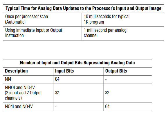
Module overview and installation process
(1) Module positioning
The 1746 series 32 channel digital I/O module is a dedicated module for SLC 500 chassis, which is divided into input modules (IB32, IV32) and output modules (OB32, OB32E, OV32). Its core function is to achieve bidirectional interaction between industrial field digital signals (such as sensors and actuators) and PLC, supporting 24V DC mainstream industrial voltage. It is designed according to “group isolation” (input 4 groups/8 points, output 2 groups/16 points) to reduce signal interference.
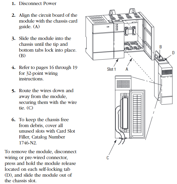
(2) Standard installation steps (power-off operation)
Power off preparation: Disconnect the chassis power supply to ensure no voltage input.
Module alignment: Align the module circuit board with the chassis card slot to avoid touching the backplane pins (to prevent static damage).
Insertion fixation: Slowly push the module into the upper and lower self-locking tabs to tighten, without the need for additional screws.
Wiring arrangement: After wiring, comb down the wires and fix them in the module slot with cable ties to avoid blocking heat dissipation or loosening.
Idle slot handling: Cover the idle slots with 1746-N2 slot filling plates to prevent dust from entering the chassis.
(3) Module disassembly
First, disconnect the external wiring or pre wired connector, press the release tabs up and down on the module, and pull out the module horizontally. Do not forcefully pull or pull it.
Core technical specifications
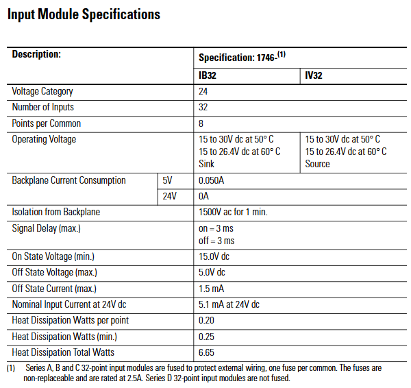
(1) Input module specifications (IB32, IV32)
Specification category 1746-IB32 (24V DC sinking input) 1746-IV32 (24V DC sourcing input)
Number of channels: 32 channels, 32 channels
8 points per group/public end (4 groups in total, isolated between groups) 8 points per public end (4 groups in total, isolated between groups)
Working voltage 15-30V DC (50 ℃), 15-26.4V DC (60 ℃) 15-30V DC (50 ℃), 15-26.4V DC (60 ℃)
Backplane current consumption 5V DC 0.050A, 24V DC 0A, 5V DC 0.050A, 24V DC 0A
Backboard isolation voltage 1500V AC (1 minute) 1500V AC (1 minute)
Signal delay (maximum) 3ms for both on/off and 3ms for both on/off
Conducting voltage (minimum) 15.0V DC 15.0V DC
Turn off voltage (maximum) 5.0V DC 5.0V DC
Turn off current (maximum) 1.5mA 1.5mA
24V DC nominal input current 5.1mA 5.1mA
Total heat dissipation power 6.65W (0.20W per point, minimum 0.25W) Total 6.65W (0.20W per point, minimum 0.25W)
Fuse protection (Series A/B/C) with 1 non replaceable 2.5A fuse per group, Series D without 1 non replaceable 2.5A fuse per group, Series D without
Specification category 1746-OB32 (Series D, 24V DC sourcing output) 1746-OB32E (24V DC sourcing with electronic protection) 1746-OV32 (Series D, 24V DC sinking output)
Number of channels: 32 channels, 32 channels, 32 channels
16 points per group/common end (2 groups in total, isolated between groups) 16 points per common end (2 groups in total, isolated between groups) 16 points per common end (2 groups in total, isolated between groups)
Working voltage 5-50V DC 10-30V DC 5-50V DC
Backplane current consumption 5V DC 0.190A, 24V DC 0A 5V DC 0.190A, 24V DC 0A 5V DC 0.190A, 24V DC 0A
Backboard isolation voltage 1500V AC (1 minute) 1500V AC (1 minute) 1500V AC (1 minute)
Signal delay (maximum) conducts 0.1ms, turns off 1.0ms conducts 0.1ms, turns off 1.0ms conducts 1.0ms, turns off 2.0ms
Turn off leakage current (maximum) 1mA 1mA 1mA 1mA
Minimum load current 1mA 1mA 1mA
Module total continuous current (maximum) 8.0A (0-60 ℃) 8.0A (0-60 ℃) 8.0A (0-60 ℃)
Single channel continuous current (maximum) 0.50A at 30 ℃, 0.25A at 60 ℃, 0.50A at 30 ℃, 0.25A at 60 ℃, 0.50A at 30 ℃, and 0.25A at 60 ℃
Continuous current per group (maximum) 4.0A (0-60 ℃) 4.0A (0-60 ℃) 4.0A (0-60 ℃)
Continuous current per pin (maximum) 2.0A (0-60 ℃) 2.0A (0-60 ℃) 2.0A (0-60 ℃) 2.0A (0-60 ℃)
Voltage drop during conduction (maximum) 1.2V (at 0.5A) 1.2V (at 0.5A) 1.2V (at 0.5A)
Surge current (per point) 1.0A/10ms at 30 ℃ (once per second), 1.0A/10ms at 60 ℃ (once every 2 seconds), 1.0A/10ms at 30 ℃ (once per second), 1.0A/10ms at 60 ℃ (once every 2 seconds), 1.0A/10ms at 30 ℃ (once per second), 1.0A/10ms at 60 ℃ (once every 2 seconds)
The total heat dissipation power is 6.45W (0.172W per point, minimum 0.95W), 8.95W (0.250W per point, minimum 0.95W), and 6.45W (0.172W per point, minimum 0.95W)
Fuse protection (Series A/B/C): 1 non replaceable 2.5A fuse per group, Series D: None (relying on electronic protection): 1 non replaceable 2.5A fuse per group, Series D: None
Protection principle: Based on thermal cut-out technology, in the event of a short circuit or overload, the faulty channel limits current within milliseconds, while other channels operate normally, and the E-Fuse LED lights up to sound an alarm.
Automatic reset: After the fault is removed, the channel cools down below the threshold and automatically recovers; Or power off and restart the module to reset, without the need to manually replace the fuse.
Limitations: It does not protect against reverse polarity wiring or AC power connection, and requires external circuit breakers to meet safety regulations.
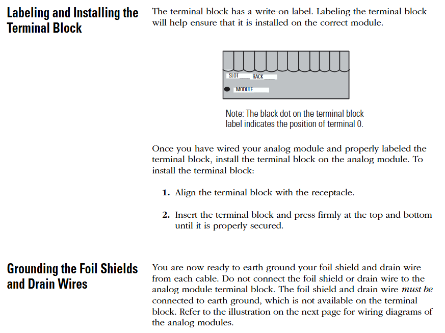
Octal Label Kit Installation (PLC Processor Only)
(1) Composition and purpose of the kit
Contains components: octal filter label, octal door label, used to replace the default decimal label of the module and adapt to the octal addressing requirements of the PLC system.
Acquisition method: It is necessary to order separately from Allen Bradley dealers, and the model must match the I/O module catalog number (refer to manual 1747-UM011 or ACIG-PL001 price list).
(2) Installation steps
Filter label: Peel off the label from the carrier paper, align the module color bar horizontally, cover decimal numbers, and press to fix.
Door label: After peeling off, directly cover the decimal label on the inside of the chassis door to ensure consistent addressing identification.
Wiring scheme and operating specifications
(1) Comes with connector wiring (Option 1:1746-N3 connector)
The components include: the module comes standard with a 40 pin female connector with keys (1746-N3) and crimping pins, supporting 22-26 AWG wires.
Pin assembly steps:
Stripping: Strip off the insulation layer of 4mm (5/32 inch) wire to expose the conductor.
Plug in: Insert the wire into the pin to the “wire stop” position.
Crimping: Use DDK 357J-5538 crimping tool (or Amp 90418-1 equivalent tool) for crimping; When there are no tools available, use sharp nose pliers to press the wire barrel and insulation barrel together, and then weld and fix them with 60% tin/40% lead rosin solder.
Fixed: Insert the pin into the connector, gently pull the wire to confirm that the “tang” is locked to prevent detachment.
Connector installation: Align the keyway of the module male connector (MIL-C-83503 standard) and lock it by pressing the upper and lower retaining arms.
(2) 1492 Wiring System (Option 2: Pre wiring Scheme)
1. System composition and advantages
Core components: 1492-CABLExx pre wired cable (with four lengths of 0.5m/1.0m/2.5m/5.0m), 1492-IFM40xx DIN rail terminal block (with/without LED status light), no need for on-site crimping, improving wiring efficiency.
Voltage drop reference (30 ℃/60 ℃):
Cable model: Voltage drop of power/common terminal wire (2A), voltage drop of output channel wire (0.5A), voltage drop of power/common terminal wire (2A), voltage drop of output channel wire (0.5A)
1492-CABLE005H 127mV 34mV 144mV 38mV
1492-CABLE10H 173mV 45mV 196mV 51mV
1492-CABLE25H 334mV 83mV 388mV 95mV
1492-CABLE50H 574mV 147mV 686mV 169mV
2. Terminal block label specifications
Label kit: The 1492 terminal block comes with multiple sets of sticker labels, indicating the module model (such as 1746-IB32) and the position of the “upper/lower” terminal block, distinguishing SLC (decimal) and PLC (octal) addressing.
Paste requirements: Select the corresponding label according to the module model and paste it on the outside of the terminal block. For example, label the “+V3” and “IN16” on the “upper” terminal block of module 1746-IV32 to ensure that the wiring corresponds.
(3) General Wiring Guidelines
Group isolation maintenance: When using the 1492 terminal block, it is necessary to choose a model that supports “group isolation” (such as with grouping partitions) to avoid signal crosstalk between different groups.
Voltage drop control: Calculate the total voltage drop (wire resistance x current x length) to ensure that the output module load terminal voltage is not lower than the minimum conduction voltage (such as 1.2V for OB32).
Public end connection:
Input module (IB32): Each group has 2 interconnected DC Com pins, which can be connected to only 1 pin; When it needs to exceed 2A, 2 should be connected.
Output module (OB32/OV32): Each group has 2+V DC (or DC Com) pins internally connected. When the current exceeds 2A, 2 pins must be connected to avoid pin overload.
Wiring diagrams and addressing instructions
(1) Core identification of diagrams
Double digit labeling: Each wiring diagram is labeled with both decimal (SLC system) and octal (PLC system) addresses, such as “IN 14” for SLC corresponding to “16 (octal)” for PLC.
Grouping division: Use “Wire Group 1-4” (input) or “Wire Group 1-2” (output) to clarify the wiring grouping, and the correspondence between the common terminal (COM1-4) and the signal terminal (IN/OUT 0-31) is clear.
(2) Typical module wiring example
1746-IB32 (sinking input):
The common terminal (DC Com 1-4) is connected to the negative terminal of 24V DC, the signal terminal (IN 0-31) is connected to the sensor output, and the+V DC 1-4 is connected to the positive terminal of 24V DC.
1746-OB32E (sourcing output with protection):
The common terminal (DC Com 1-2) is connected to the negative terminal of the load, the signal terminal (OUT 0-31) is connected to the positive terminal of the load, and the+V DC 1-2 is connected to the positive terminal of 24V DC. The E-Fuse LED corresponds to the fault channel.
1746-NI8 is an 8-channel analog input module of the SLC 500 series, used to collect DC voltage or current signals from industrial sites (such as sensor and transmitter outputs), convert analog signals into digital signals recognizable by PLC through built-in analog-to-digital (A/D) converters, achieve equipment status monitoring and process control, and adapt to fixed and modular SLC 500 processors.
(2) Core functions and hardware features
Category specific description
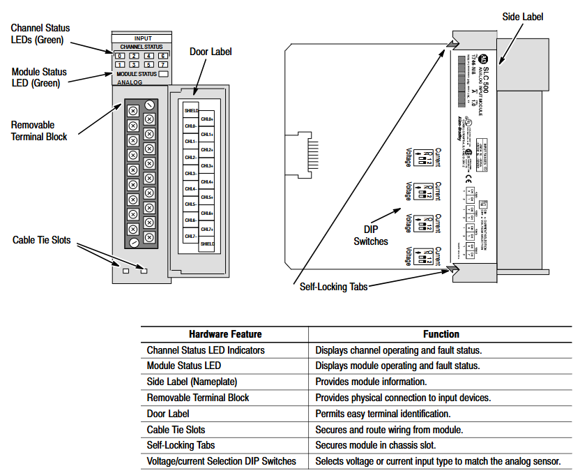
Hardware design -8 high impedance input channels, supporting single ended or differential wiring;
-Comes with a detachable terminal block (spare part number 1746-RT25G) for easy wiring and maintenance;
-The panel contains 9 green LED indicator lights: 8 channel status lights (corresponding to 8 input channels), 1 module status light, which intuitively displays the operation and fault status;
-Side mounted DIP switch for selecting channel input type (voltage/current).
System compatibility – supports two interface modes, Class 1 and Class 3:
-Class 1 (default): Suitable for SLC 500 fixed type, SLC 5/01/02/03/04 processors, occupying 8 output configuration words and 8 input data words;
-Class 3 (Advanced): Only compatible with SLC 5/02/03/04 processors, with additional support for user-defined scaling and channel status word monitoring, occupying 12 output configuration words and 16 input words (including 8 data words and 8 status words).
Key feature – Automatic calibration: All enabled channels undergo continuous temperature compensation and automatic calibration without the need for manual triggering;
-Fault diagnosis: supports fault detection such as open circuit, over range, and configuration errors, and provides feedback through LED and status words;
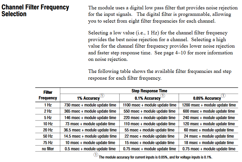
-Filtering function: Programmable digital low-pass filtering (8 frequencies to choose from), balancing noise suppression and response speed.
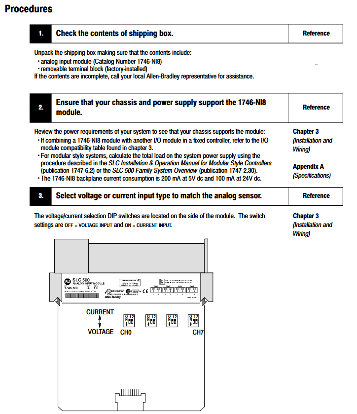
Quick Start Guide
For users with experience using SLC 500, a simplified deployment process is provided, with the following core steps:
Equipment preparation: Screwdrivers, analog input devices (such as sensors), shielded cables (recommended Belden 8761), SLC processors and power supplies, and programming equipment (such as RSLogix 500) need to be prepared.
Hardware inspection: Confirm that the packaging contains 1746-NI8 modules and pre installed terminal blocks. If missing, please contact the supplier.
Power compatibility: The module is powered through the backplane and consumes 5V DC 200mA and 24V DC 100mA. It is necessary to ensure that the chassis power load is sufficient (refer to manual 1747-6.2 to calculate the total load).
DIP switch setting: Adjust the side DIP switch (OFF=voltage, ON=current) according to the input type (voltage/current).
Module installation: Insert the chassis into any non processor slot while powered off (it is recommended to install it in the rightmost slot in high-temperature environments for higher temperature tolerance), and tighten the self-locking buckle.
Wiring: Use shielded cables to connect the sensor to the terminal block. Single ended signals can be short circuited to the common terminal, while differential signals should pay attention to the common mode voltage (≤± 10.5V). The shielding layer should be grounded at one end (channels 0-3 should be connected to the top shielding terminal, and channels 4-7 should be connected to the bottom).
System configuration: Set the module ID code (3526 for Class 1 and 12726 for Class 3) through programming software. Class 3 requires an additional configuration of 16 input words and 12 output words.
Channel configuration: Define channel configuration words (such as input type, data format, filtering frequency) in the ladder program, and download them to the module output image area through the COPY instruction.
Startup verification: It is normal for the module status light and the enabled channel light to remain on after power on; If the light flashes or does not light up, refer to Chapter 7 for troubleshooting.
Installation and wiring
(1) Installation specifications
Static protection: Wear a grounding wristband during operation to avoid touching the back panel pins, and store in an anti-static bag when idle.
Slot selection:
Modular chassis: can be installed in any slot except slot 0 (processor slot);
Fixed expansion chassis (1746-A2): Please refer to the compatibility table (if combined with OB16 module, confirm current load), and some combinations require external power supply.
Temperature adaptation: The working temperature of the regular slot is 0-55 ℃, and the rightmost slot is 0-60 ℃. Avoid approaching high heating modules (such as 32 point I/O modules) or strong interference sources (such as frequency converters).
Installation steps: Align the upper and lower guide slots of the chassis, slowly push them into the buckle lock, and install the 1746-N2 filling plate in the idle slot.
(2) Wiring requirements
Specification for Wiring Types
The terminal block has 18 detachable terminals, including 2 shielded terminals, supporting up to 14 AWG wires, and terminal screw torque ≤ 5 lb in (0.565 Nm).
The single ended input signal is connected positively to CHx (+) and negatively to CHx (-), and the multi-channel common terminal can be short circuited to reduce wiring.
The common mode voltage of the differential input signal source should be ≤± 10.5V. It is forbidden to connect the common terminal of the signal source to the module to avoid grounding loops.
The power module does not provide sensor power and needs to be separately matched with a DC power supply of the transmitter specifications (such as 24V DC).
Run basic configuration
(1) Module identification and addressing
ID code setting: The corresponding ID code (Class 1:3526, Class 3:12726) needs to be entered in the programming software. Early versions of RSLogix 500 only supported Class 1 and need to be upgraded to v1.30+to support Class 3.
Memory Mapping:
Class 1: Output image O: e.0-O: e.7 consists of 8 channel configuration words, while input image I: e.0-I: e.7 consists of 8 channel data words;
Class 3: The output image contains an additional O: e.8-O: e.11 (2 sets of scaling upper and lower limits), and the input image I: e.8-I: e.15 consists of 8 channel status words.
(2) Key parameter calculation
Module update time: The total sampling conversion time for all enabled channels is 0.75ms for a single channel and 6.0ms for 8-channel full configuration (independent of filtering frequency).
Channel response time:
Start time (enable until status word update): 101-107ms;
Shutdown time (from disabled to data reset): 1-7ms;
Reconfigure time (modify configuration): 101-107ms (excluding data format modifications).
Filtering and Anti aliasing:
The filtering frequency determines the step response (such as achieving 1% accuracy in 730ms for 1Hz filtering, and only 0.5ms without filtering);
Aliasing frequency=1/(number of enabled channels x 0.00075), channel 1 is 1333Hz, and channel 8 is 167Hz. It is necessary to ensure that the signal frequency is lower than the aliasing frequency.
Channel configuration and data processing
(1) Detailed Explanation of Configuration Words
Each channel configuration word (16 bits) defines the channel working mode, and the key bits have the following meanings:
Description of Range Function Options
The voltage (± 10V/1-5V/0-5V/0-10V) and current (0-20mA/4-20mA/± 20mA/0-1mA) of the 0-2 input type should be consistent with the DIP switch
3-5 data format engineering unit (1mV/1 μ A step) Scaled-for-PID(0-16383)、 Proportional counting (-32768-32767), NI4 compatible format, Class 3 user-defined
6-7 open circuit state is only valid for 4-20mA, with optional zero value, upper limit value, and lower limit value
11 channel enable 1=enabled (participating in sampling), 0=disabled (data reset)
12-15 reservation needs to be set to 0
(2) Data scaling
The digital output of the module needs to be converted into actual engineering units (such as temperature and pressure), supporting multiple scaling methods. Examples are as follows:
Engineering unit: directly corresponding to physical quantities (such as 4-20mA corresponding to 100-500 ℃, data word 5500 → 247.5 ℃);
Scaled for PID: adapted to SLC PID instructions, 0 corresponds to lower limit, 16383 corresponds to upper limit (e.g. 4-20mA corresponds to 212-932 ° F, data word 5500 → 453.71 ° F);
User defined (Class 3): Set two sets of zoom ranges through O: e.8-O: e.11 and map them proportionally (e.g. 0-10V corresponds to 0-200psi, data word 16600 → 166psi).
(3) Status word monitoring (Class 3)
The input images I: e.8-I: e.15 are channel status words, and the key bits provide feedback on the operating status
Position 0-2: Current input type;
Position 3-5: Current data format;
Bit 11: Channel enable status (1=enabled);
Bit 12: Open circuit error (1=detected);
Bit 13: Over range error (1=input exceeds upper limit);
Bit 14: Under range error (1=input exceeds lower limit);
Bit 15: Configuration error (1=invalid configuration word).
Example of trapezoidal logic
Provide ladder diagram examples of typical programming scenarios, including:
Initialization configuration: Use the first scan bit (S: 1/15) to copy the preset configuration word (stored in the N10 file) to the module output image area (such as O: 3.0-O:3.7) through the COP instruction, and batch enable 8 channels.
PID interface: Set the channel data to Scaled for PID format and directly use it as a process variable (PV) for PID instructions without intermediate scaling (e.g. I: 3.0 → PID control block N11:23).
Fault alarm: Monitor the open circuit error bit of the Class 3 status word (such as I: 3.8/12), trigger the output point (such as O: 2.0) to drive the alarm light.
Diagnosis and troubleshooting
(1) LED status interpretation
Solution to the cause of module status light channel status light malfunction
Always on, always on. Normal operation without operation required
Constant flashing, open circuit/over range/configuration error 1. Check wiring and sensors; 2. Confirm that the configuration word is valid; 3. Check the status word to locate the error type
Extinguish module fault/not powered on 1. Check the power supply of the backplane; 2. Re plug and unplug the module; 3. Contact technical support
Constant on/off channel not enabled. Set bit 11=1 in the configuration word to enable channel
(2) Common troubleshooting
Open circuit error: Only 4-20mA channel, check for sensor disconnection, loose terminals, response time ≤ 6ms (8-channel full configuration).
Over range error: Input signal exceeds the configured type range (such as 4-20mA channel input<3.5mA or>20.5mA), calibrate sensor or adjust configuration.
Configuration error: The configuration word position setting is invalid (such as setting the data format to 110), and the configuration word needs to be redefined.
Noise interference: If the analog signal fluctuates greatly, check the shielding grounding, stay away from the power line, or reduce the filtering frequency (if set to 1Hz).
Technical support: Module fault symptoms, LED status, image data, processor model and firmware version are required. Contact Allen Bradley customer service (Americas: 1-888-565-4155; Europe:+800-44444-8001; Asia:+86-400-842-8599).
Application examples
Provide two practical cases covering both basic and advanced scenarios:
Basic case: Monitoring single-phase motor current, 4-20mA signal corresponding to 0-100A, channel 0 set as engineering unit+10Hz filtering, program converts data into BCD format to drive LED display screen (TOD command required).
Advanced case: Multi parameter monitoring (three-phase motor current, tank pressure, liquid level), switching the display current phase sequence through a selection switch, triggering high and low level alarms when the liquid level exceeds the limit, and configuring different input types (current/voltage) for each of the 5 channels.
Model attribution: 1746-IB32 is a digital input module of Rockwell Automation SLC 500 series programmable logic controller (PLC), mainly used for collecting discrete switch signals (such as on/off signals output by sensors, buttons, limit switches, etc.) in industrial sites, and converting them into digital signals recognizable by PLC to achieve real-time monitoring of equipment status.
Typical application scenarios: Widely used in manufacturing production lines, mechanical equipment control, process automation and other fields, such as assembly line workstation status detection, motor start stop signal acquisition, safety door switch status monitoring, etc.
The single module supports 32 independent digital input channels and can simultaneously collect 32 switch signals. The channels are electrically isolated to avoid signal interference
The input signal type is direct current (DC), which usually supports two common industrial DC voltages: 24V DC or 120V DC (please refer to the official document for details), and is compatible with NPN or PNP sensor outputs
Input response time ≤ 1ms (typical value) to quickly respond to on-site signal changes, ensuring real-time control logic, suitable for scenarios with high response speed requirements
Low power design with input current of 7mA~10mA (per channel), reducing overall system energy consumption, and compatible with the output current range of most industrial sensors
(2) Electrical and Protection
Isolation method: Adopt channel to channel optoelectronic isolation or group isolation (such as isolation every 8/16 channels), with isolation voltage usually ≥ 250V AC (1 minute), effectively suppressing electromagnetic interference (EMI) and grounding loop problems in industrial sites.
Overvoltage/Overcurrent Protection: Some models have built-in overvoltage protection circuits (such as transient voltage suppressors TVS) and overcurrent protection (such as self recovery fuses) to prevent module damage from abnormal voltage/current on site.
(3) Physics and Installation
Dimensions: Suitable for SLC 500 series standard racks (such as 1746-A7/A10, etc.), usually designed as a “thin module”, with a width of about 32mm, a height matching the rack (about 100mm), and a depth of about 160mm (subject to official data), saving rack installation space.
Installation method: It is installed using DIN rails or directly fixed on the SLC 500 rack backplane. During installation, it is necessary to ensure that the module is reliably connected to the rack bus to ensure stable data transmission and power supply.
(4) Environmental adaptability
Working temperature: -20 ℃~60 ℃ (industrial standard), can operate stably in high and low temperature industrial environments, such as workshops, warehouses, outdoor control cabinets, and other scenarios.
Humidity range: 5%~95% RH (non condensing), suitable for humid environments, no additional moisture-proof measures required (requires overall protection of the control cabinet).
Protection level: The protection level of the module itself is usually IP20 (for panel installation), and it needs to be installed in a closed control cabinet to avoid direct contact with dust and liquids.
Functional characteristics (based on the commonality of SLC 500 series modules)
Diagnostic function: Supports channel level fault diagnosis, such as open circuit and short circuit detection. Diagnostic information can be read through PLC programming software (such as RSLogix 500) to quickly locate the faulty channel and reduce troubleshooting time.
Compatibility: Fully compatible with all SLC 500 series CPU modules (such as 1747-L511/L532, etc.), can be mixed with digital output modules (such as 1746-OB16) and analog modules (such as 1746-NI8) of the same series for installation, and build a complete control system.
Wiring method: Adopting a detachable terminal block (such as 1746-TB32 terminal board), supporting “front wiring” or “rear wiring”, the wiring operation is convenient, and the terminal block can be directly disassembled for later maintenance without dismantling the entire module.
Precautions for use
Power supply requirements: The module is powered by the SLC 500 rack backplane (usually a 5V DC logic power supply+24V DC input power supply). It is necessary to ensure that the rack power module (such as 1746-P2) outputs stably to avoid voltage fluctuations that may cause module failures.
Signal wiring: Input signal lines should be routed separately from power lines (such as motor cables) to reduce electromagnetic interference; When wiring for long distances (over 100m), shielded twisted pair cables should be selected and properly grounded.
Module address setting: If multiple modules of the same type are installed in the rack, a unique address needs to be set through the address dip switch on the module to ensure that the PLC can correctly identify each module channel.
Software configuration: In RSLogix 500, it is necessary to correctly configure the module type (select “1746-IB32”) and input filtering time (which can be set according to the on-site interference situation, such as 0.1ms~10ms) to avoid false triggering caused by high-frequency interference.