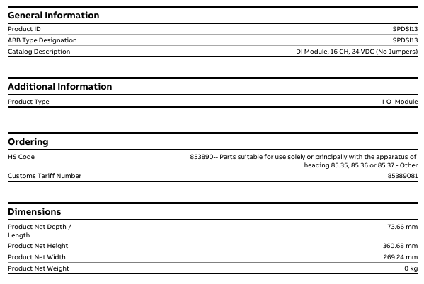
Product ID/Model: IMDSI13 (ABB official model identification), document associated link labeled “SPDSI13”, speculated to be due to differences in series ownership or regional model labeling, core parameters are based on “IMDSI13”.
Product type: I-O-Module, specifically Digital Slave Input Module, is positioned as a slave device for Symphony Plus control system, receiving external digital signals and transmitting them to the main control system.
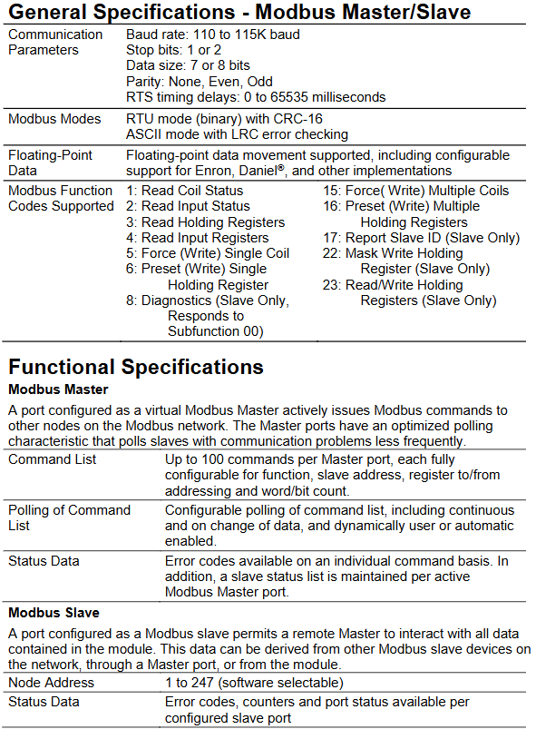
Belonging to the product system: classified under ABB’s “Products”, “Control Systems”, “Symphony Plus”, “I/Os”, HR Series (Harmony Rack) I/O “, which is the HR series (Harmony Rack) I/O module family under the Symphony Plus control system, suitable for rack mounted installation and system integration of this series.
2. Multi language support
The document page supports viewing in 16 languages (including Chinese, English, German, Japanese, Korean, etc.), making it convenient for users from different regions to access technical information. The corresponding version can be selected through the page language switching function.
Key physical and compliance parameters
1. Size and weight
Dimensions: The product has a net depth/length of 73.66mm, a net height of 360.68mm, and a net width of 269.24mm. It is compatible with the installation dimensions of the HR series (Harmony Rack) rack and requires confirmation of specific installation compatibility based on rack specifications.
Weight: The document indicates “0 kg”, which is speculated to be a simplified net weight label without packaging or data is currently missing. The actual weight of industrial I/O modules is usually around a few hundred grams to 1 kilogram, and the final technical document from ABB should be used as the standard.
2. Environmental and Compliance Attributes
WEEE classification: Belongs to “5. Small Equipment (No External Dimension More Than 50 cm)”, which means “small equipment (with no external dimensions exceeding 50 cm)” and meets the classification requirements of the EU Waste Electrical and Electronic Equipment Directive (WEEE). Disposal must comply with corresponding environmental standards.
Battery related: Excluding batteries (Number of Batteries: 0), there is no need to consider additional operations related to battery replacement and environmental recycling.
3. Import and export and tariff information
HS code: 853890 (specific sub target note: “853890- Parts suitable for use completely or primarily with the apparatus of heading 85.35, 85.36 or 85.37- Other”), which means “parts specifically or primarily used for equipment of heading 85.35, 85.36 or 85.37, other”.
Customs tariff code: 85389081, used for tariff accounting and classification during import and export customs declaration. The specific tax rate needs to be confirmed in conjunction with the customs policies of the importing region.
Installation precautions
First, the importance of industrial equipment installation
In modern industrial production, various equipment and machines are widely used in various fields, such as manufacturing, energy industry, chemical industry and so on. The installation of industrial equipment is directly related to production efficiency and product quality. Proper installation and commissioning of good equipment can ensure the stable operation of the production line, improve production efficiency and product quality, reduce maintenance costs, and ensure the safety of employees.
Second, the steps of industrial equipment installation
1. Preparation: Before the installation of industrial equipment, it is necessary to carry out adequate preparation work. This includes the tools and equipment required for installation, cleaning and preparation of the installation site, and making installation plans and schedules.
2. Determine the installation position: Determine the installation position of the equipment according to the requirements of the equipment and the layout of the production line. When determining the location, the weight and size of the equipment need to be considered, as well as the coordination of the equipment with the surrounding environment.
3. Install the device: Assemble and install the device according to the installation instructions. Ensure that the device is securely and accurately connected, while protecting the appearance and internal components of the device.
4. Connect power supplies and pipelines: For devices that require power supplies and power supplies, properly connect power supplies and pipelines. The connection of power supply and pipeline should comply with safety standards to avoid hazards such as electric shock and leakage.
5. Commissioning the device: After the installation is complete, you need to commission the device to ensure that the device can run properly. It includes checking the functions and performance of the equipment, adjusting the parameters and Settings of the equipment, and carrying out the necessary tests and inspections.
6. Training operators: After the installation of the equipment, it is necessary to train the operators to understand the operation methods and precautions of the equipment, and improve the operation skills and safety awareness of the employees.
1. Safety first: When installing industrial equipment, safety is the most important consideration. You must operate in strict accordance with safety regulations and wear necessary protective equipment to ensure the safety of the workplace.
2. Strictly follow the equipment instructions: Industrial equipment usually comes with detailed installation instructions, you must carefully read and understand the contents of the instructions, and install the operation in accordance with the requirements of the instructions.
3. Pay attention to the assembly sequence: When installing the device, follow the correct assembly sequence to ensure that all components of the device are assembled correctly to avoid equipment failures or safety accidents caused by incorrect assembly sequence.
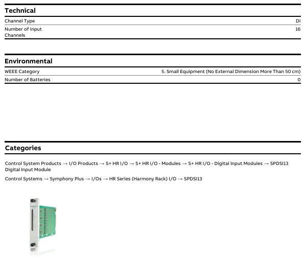
Eaton XV-102 is an industrial grade touch display screen that combines HMI (Human Machine Interface) and integrated HMI/PLC functions, suitable for mechanical manufacturing, system integration and other scenarios. It can achieve equipment monitoring, parameter setting and process control, with multiple size models, rich communication interfaces and industrial grade protection performance, and meets multiple international safety and industry certification standards.
Product positioning and core functions
Functional positioning: It can be used as an independent HMI terminal or integrated HMI/PLC device, with the core used for monitoring, operating, and controlling machines and systems in industrial scenarios. It does not support safety functions related to personnel or equipment safety protection.
Applicable scenarios: Mainly aimed at the fields of mechanical manufacturing and system construction, it can also be used in maritime scenarios through classification certification (DNV GL), and must meet specific installation and protection requirements.
Product model and hardware configuration
1. Equipment model classification
XV-102 offers three screen sizes (3.5 inches, 5.7 inches, 7.0 inches) and multiple versions (A/B/D/E/H types), with core differences reflected in display performance, communication interfaces, and expansion functions. The specific parameters are shown in the table below:
Model Version Screen Specification (Size/Resolution/Color) Core Interface Configuration Special Function Model Example
Version A 3.5-inch TFT-LCD (QVGA/32 grayscale) Ethernet USB Device, Optional Profibus/RS232/RS485/CAN 1 SD card slot, no additional expansion XV-102-A2-35MQR
Version B 3.5-inch TFT-LCD (QVGA/32 grayscale or 64K color) Ethernet USB Device, Optional RS232/RS485/CAN/Profibus/SmartWire DT Master 1 SD card slot, supports SmartWire DT Master (some models) XV-102-BE-35TQR
Version D 5.7-inch (VGA/64K color), 7.0-inch (WVGA/64K color) Ethernet USB Device/Host, Optional RS232/RS485/CAN/Profibus 1 SD card slot, large screen compatible with complex interface XV-102-D8-70TWR
Version E 5.7-inch (VGA/64K color), 7.0-inch (WVGA/64K color) Ethernet USB Device/Host, Support RS485+CAN/Profibus+SmartWire DT Master 1 SD card slot, enhance SmartWire DT integration XV-102-E6-57TVR
Version H 3.5/5.7/7.0 inches (64K colors) Ethernet, USB Device/Host (only 5.7/7.0 inches), optional RS232/RS485 basic communication function, suitable for simplified scenarios XV-102-H3-57TVR
Packaging and Accessories
The packaging contents of devices of different sizes may vary slightly, and the core accessories are as follows:
3.5-inch device: 1 touch screen, 4 mounting brackets with top wires, 1 sealing strip, 1 power connector (models with SmartWire DT include an additional SmartWire DT power connector).
5.7-inch device: 1 touch screen, 6 mounting brackets, 1 sealing strip, 1 power connector (models with SmartWire DT include an additional dedicated power connector).
7.0-inch device: 1 touch screen, 8 mounting brackets, 1 sealing strip, 1 power connector (models with SmartWire DT include an additional dedicated power connector).
Optional accessories: 10 touch pens (model ACCESSORIES-TP-TEN-10, item number 139808), need to be ordered separately.
Safety regulations and equipment protection
1. Core security warning
The manual clearly divides the danger level and provides protection requirements. The key warnings are as follows:
Explosion risk: In the potentially explosive environment of Zone 22, disconnecting the live interface or mechanical impact may cause an explosion. It is only used in non hazardous areas or Zone 22; Grounding resistance<10 ΩΩ; Avoid mechanical impact; After power failure, unplug and plug the interface again
There are live parts inside the electric shock risk equipment, and opening the cover may cause electric shock. Do not open the cover by yourself; Only operated by professionals
Static electricity damage: Static discharge may damage electronic components by touching grounded metal before coming into contact with equipment, releasing static electricity; Avoid touching interface pins
Data loss: When reading or writing from an SD card, power failure or unplugging the card may cause data damage. Only when the device is powered off and the SD card is unplugged or unplugged; Reduce SD card write operations (limited write life)
When a sudden change in temperature and humidity caused by a condensation short circuit leads to internal condensation of the equipment, it is forbidden to power on the equipment; Start up after the temperature stabilizes
2. Personnel and operational requirements
Personnel qualifications: Installation and operation personnel need to have industrial automation equipment operation qualifications, be familiar with this manual and relevant safety standards (such as UL 508, IEC/EN 61131-2).
Operating standards: The complete manual must be used (it is prohibited to split a single page for use to avoid missing safety information); Strictly follow the manual requirements for installation, wiring, and maintenance, and unauthorized modification of equipment is prohibited.
Installation and interface configuration
1. Installation requirements
(1) Environmental and location conditions
General requirements: Installed in control cabinets, control panels, or workstations, avoiding direct sunlight (to prevent plastic aging); Vertical installation tilt angle ≤ ± 45 ° (without forced ventilation); Ventilation gap ≥ 3cm (from ventilation opening), ≥ 15cm (from heating components such as transformers).
Special certification requirements:
Maritime Certification (DNV GL): A 24V DC power anti-interference filter must be installed, communication cables must be shielded, and comply with DNVGL-CG-0339 standard.
UL certification: environmental temperature ≤ 50 ℃, pollution level 2; The tightening torque of the power terminal is 0.6-0.8 Nm (5-7 Lb. In).
Installation steps: Make holes on the installation surface → Paste sealing strips (the joint should be at the bottom of the equipment without gaps) → Insert the equipment from the front → Fix with corresponding numbers of brackets (4 in 3.5 inches, 6 in 5.7 inches, and 8 in 7.0 inches, ensuring IP65 protection), and tighten the bracket top thread with a torque of ≤ 0.1 Nm (to prevent damage to the equipment).
2. Interface configuration and wiring
XV-102 provides rich industrial interfaces, supporting multi protocol communication and expansion. The core interface parameters are as follows:
Interface type specifications and functional wiring requirements
Power interface 24V DC SELV (safe ultra-low voltage), voltage range 19.2-30V DC, maximum power consumption of 5W for 3.5-inch, maximum 9.5W for 5.7/7.0-inch, using Phoenix MSTB 2.5/3-ST-5.08 connector (built-in); XT-FIL-1/2 anti-interference filter needs to be installed (for maritime/EMC B-level scenarios)
Ethernet 100Base TX/10Base-T (RJ45), supporting LED status indication (ACT flashing=data transmission, LINK constantly on=network connection) using shielded twisted pair (STP); Cross wires are used between devices, and straight wires are used to connect to switches; Maximum length 100m
RS232 (system port) 9-pin D-Sub male, non isolated, supports up to 115200 bit/s (within 2.5m) with shielded cable; The cable length is negatively correlated with the baud rate (e.g. ≤ 9600 bit/s at 30m); The GND terminal must be connected
RS485 9-pin D-Sub male, non isolated, supports 32 slave stations, and requires 120 Ω terminal resistors at both ends of the bus using shielded twisted pair cables; Maximum length 500m (0.75mm ² wire diameter); The GND terminal must be connected
CAN 9-pin D-Sub male head, non isolated, compliant with CiA standard, supports 32 shielded twisted pair cables with characteristic impedance of 120 Ω for slave stations; Maximum length of 5000m (at 10 kbit/s); Terminal resistors are required at both ends of the bus
Profibus 9-pin D-Sub female head, non isolated, up to 1.5 Mbit/s (within 200m) using Profibus Class A shielded twisted pair (impedance 150 Ω); Terminal resistors are required at both ends of the bus; 5V pin prohibits external power supply
SmartWire DT Master 8-pin interface (SWD)+POW/AUX power interface, non isolated, supports up to 99 SWD modules with dedicated SWD cables (such as SWD4-100LF8-24); UAUX requires external 2A circuit breaker (UL standard) or 3A fuse (DIN standard)
USB USB 2.0(Device Type B/Host Type A), Non isolated shielded USB cable; Maximum length of 5m; Host interface supports external devices such as USB drives
Operation and Maintenance
1. Basic operations
Power on and off: No physical switch, automatically boots when powered on, shuts down when powered off; For the first startup, please refer to the “Windows CE System Instructions” (MN05010007Z) to configure system parameters and install applications.
SD card operation: Only plug and unplug when the device is powered off; Used to store project files or data, avoiding frequent writes (limited lifespan); Power off is prohibited during reading and writing.
Touch calibration: It has been calibrated at the factory. If there is an abnormal response, it needs to be recalibrated using system tools (refer to the “Windows CE System Instructions”); Operate only with fingers or a dedicated stylus, and avoid touching with sharp objects (to prevent damage to the resistive screen).
2. Maintenance and troubleshooting
(1) Daily maintenance
Cleaning: Use a clean, soft, and damp cloth to wipe the resistance screen. For stubborn stains, dip a small amount of detergent in it; Do not use sharp tools, corrosive solvents, or liquids to infiltrate the equipment.
Battery maintenance: Built in CR2032 lithium battery (3V/190mAh), non replaceable, can maintain real-time clock for about 10 years after power failure.
Repair restriction: Self opening repair is prohibited. Contact Eaton authorized repair center or supplier.
(2) Common fault handling
Possible causes and solutions for the fault phenomenon
The device cannot start and the power supply is not properly connected or the voltage is abnormal. Check the 24V DC power supply wiring; Confirm that the voltage is within the range of 19.2-30V DC
Touch screen unresponsive/response deviation touch screen not calibrated; Install the bracket too tightly and recalibrate the touch screen; Loosen the top wire of the bracket (torque ≤ 0.1 Nm)
Display screen black, backlight not activated or malfunction check, backlight settings in visualization software; Fault needs to be returned to the factory for repair
Communication interruption (such as Ethernet/CAN) cable not connected properly; Terminal resistor missing; Interference check cable wiring; Confirm the connection of 120 Ω terminal resistors at both ends of the bus; Install anti-interference filter or magnetic ring
Technical parameters and compliance certification
1. Core technical parameters
Parameter category specification
Display performance of 3.5 inches (QVGA/32 grayscale/64K color), 5.7 inches (VGA/64K color), 7.0 inches (WVGA/64K color); The lifespan of LED backlight is about 40000 hours, and the brightness can be adjusted by software
System configuration: 32-bit RISC processor (400MHz); 64MB DRAM + 64MB NAND Flash; Some models include 125KB NVRAM
Protection level: IP65 on the front (requires correct installation of brackets), IP20 on the back
Environmental adaptability: working temperature 0-50 ℃, storage temperature -20-60 ℃; Relative humidity ranging from 10% to 95% (without condensation); Anti vibration (5-150Hz, 2g), anti impact (15g/11ms)
Power supply characteristics: 24V DC SELV, with reverse polarity protection and built-in fuses; Start impulse current 1.5A/2s
2. Compliance certification
Safety and EMC: Compliant with UL 508 (Industrial Control Equipment), UL 60950 (Information Technology Equipment), CE (EMC Directive 2014/30/EU); ATEX 2014/34/EU (Zone 22, 3D explosive environment).
Industry certification: DNV GL classification certification (TAA00000NC), suitable for maritime scenarios; Compliant with IEC/EN 61131-2 (Requirements for PLC Equipment) and EN 50178 (Electronic Equipment for Power Installation).
Storage, transportation, and disposal
Storage: ambient temperature -20-60 ℃, relative humidity 10% -95% (no condensation); Avoid direct sunlight, vibration, and chemical corrosion.
Transportation: Use original packaging to avoid impact and compression; The transportation environment must meet the storage conditions, and upon arrival, inspect for any transportation damage.
Disposal: The equipment contains lithium batteries (CR2032, containing 1.2-dimethoxyethane), which need to be professionally disposed of according to local environmental standards or returned to Eaton for disposal; The packaging materials (cardboard, PE bags) are recyclable.
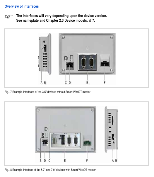
ProSoft MVI56-MCM is a product designed specifically for Rockwell Automation ® ControlLogix ® The Modbus master-slave communication module designed by the processor enables convenient integration between the ControlLogix system and other devices that support the Modbus protocol, such as PLCs, process control devices, and SCADA systems. As an interface module between the Modbus network and the ControlLogix backplane, it has high compatibility, ease of configuration, and reliable communication performance.
Core Features and Advantages
The module meets the flexible communication and efficient operation and maintenance needs in industrial scenarios through targeted design. The core features and corresponding values are as follows:
Characteristics classification, specific characteristics, advantages
Backboard technology authorized by Rockwell Automation; Support 1756 backplane single slot installation (local/remote rack) 1. Implement high-speed data transmission between modules and ControlLogix processors
2. Compatible with ControlLogix system architecture, no additional hardware adaptation required
The protocol supports Modbus RTU (binary, with CRC-16 checksum) and Modbus ASCII (with LRC error checksum) protocols; Support floating-point data transmission (including Enron and Daniel) ® 1. Adapt to the communication requirements of different Modbus devices, with wide compatibility
2. Meet the transmission requirements of high-precision data (such as flow and temperature) in industrial scenarios
Configuration and Monitoring 1. Based on RSLogix ™ 5000 configuration, supports viewing module data and status through controller tags
2. Provide example ladder diagrams with complete annotations (including user-defined data types, steps, and labels), which can be used in most scenarios without modification
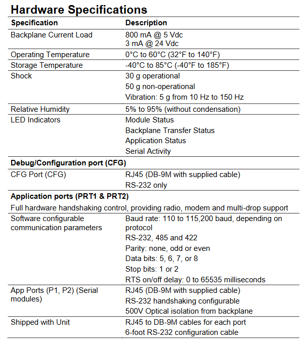
3. LED diagnostic indicator lights (module status, backplane transmission status, application status, serial activity)
4. Menu driven hardware and protocol diagnostic tools; Support viewing module database content through serial port connection to PC 1. Reduce configuration threshold and shorten deployment time
2. Operations personnel can quickly locate faults (such as communication interruptions, module abnormalities), reducing downtime
20 years of experience in developing industrial communication solutions with technical support and warranty; Global free unlimited technical support (pre-sales, deployment, troubleshooting); 3-year warranty: 1. Ensure long-term stable operation of equipment and reduce maintenance risks
2. Global service network ensures timely access to support and adapts to cross-border project needs
Functional specifications
The module supports both Modbus master and slave modes, allowing for flexible configuration of port roles according to different communication topology requirements.
(1) Modbus master mode
After configuring the port as a master, it can actively send instructions to slave devices in the Modbus network, with intelligent polling and detailed status feedback capabilities:
Instruction configuration: Each master port supports up to 100 configurable instructions, each of which can customize function codes, slave addresses, register read/write addresses, and word/bit counts.
Polling strategy: supports flexible instruction list polling configuration, including continuous polling, polling when data changes, and can be manually or automatically enabled for polling; For slave stations with abnormal communication, the polling frequency will be automatically reduced to optimize network resource utilization.
Status feedback: Provide error codes for individual instructions and maintain a list of slave status for each active master port for troubleshooting purposes.
(2) Modbus Slave Mode
The port is configured to allow remote master access to all data within the module after the slave station (data can come from other Modbus slave stations in the network, master station ports, or the module itself):
Node address: Supports 1-247 software selectable addresses, suitable for multi device networking requirements.
Status monitoring: Each configured slave port provides error codes, counters, and port status data, providing real-time feedback on communication health.
(3) Supported Modbus Function Codes
Covering commonly used read and write operations in industrial scenarios to meet data collection and control requirements:
Function code function description applicable mode (master/slave)
1. Read the status of the coil from the master station (sending) and slave station (responding)
2. Read input status: master station (sending), slave station (responding)
3 Read and hold register master (send), slave (respond)
Communication standard: Supports RS-232/485/422, with full hardware handshake control (suitable for radio stations, modems, and multi machine networking scenarios)
Communication parameters: baud rate 110-115200 baud (depending on the protocol); Data bits 5/6/7/8; Stop position 1/2; Check bit none/odd/even; RTS switch delay 0-65535 milliseconds (software configurable).
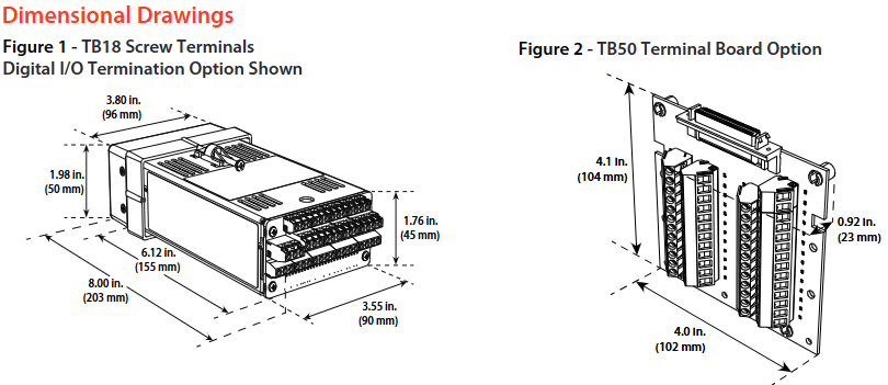
The Watlow Series CLS200 is a compact loop control system that provides powerful control functions in a 1/8 DIN package. It features multi loop control, flexible input-output configuration, and multiple firmware options, making it suitable for a wide range of industrial control scenarios and complying with multiple international safety and electromagnetic compatibility standards.
Core product features and advantages
Multi loop PID control: Available in 4, 8, and 16 loop versions, it can simultaneously control heating and cooling circuits, saving panel space and reducing installation time for each loop, with fewer parts, and improving system reliability.
Intelligent control function: equipped with Auto tune function, parameter tuning can be quickly completed without the need for professional personnel, ensuring control accuracy; Supports storing and calling 8 job programs, making it easy to quickly switch production processes.
Flexible input support: Compatible with multiple sensor inputs, including thermocouples (Type B/E/J/K/R/S/T, etc.), RTDs (only supported for 4/8 loop models, divided into 2 ranges), linear DC voltage/current, and pulse signals, reducing learning costs and inventory pressure; Equipped with sensor fault detection, it can quickly troubleshoot issues such as reverse wiring, short circuits, and open circuits.
Intuitive operation and communication: equipped with a 32 character vacuum fluorescent display screen and an 8-key keyboard, menu guided operation, supporting single channel/multi-channel display switching; Built in EIA/TIA-232 and 485 serial communication interfaces, can be connected to computers or software to achieve configuration loading, data acquisition, and integration with other controllers. The baud rate can be selected from 2400, 9600, 19200, and supports ANSI X3.28-1976 (compatible with Allen Bradley PLC/2) and Modbus ® RTU protocol.
Alarm and output configuration: Each input channel has high/low process alarms and deviation alarms, and the alarm dead zone, delay, and startup suppression can be customized; Up to 34 digital outputs are provided (depending on the wiring method), which can be configured as switch time proportional control or distributed zero crossing control. The maximum sinking current for a single output is 60mA (5VDC), and the onboard power supply provides 350mA (5VDC) power supply; There are also global alarm outputs (triggered by any alarm) and watchdog outputs (indicating normal operation of the controller).
Firmware Options
According to application requirements, different firmware functions can be selected to meet basic to complex control scenarios:
Standard firmware closed-loop PID control, automatic tuning, alarm, job storage, sensor fault detection, basic temperature/process control, without the need for complex timing or special algorithms
The Ramp and Sok firmware includes standard functions, including temperature control programs and process variable retransmission. In batch production, heating is required according to specific temperature curves (such as material annealing and food processing)
The enhanced firmware includes standard features such as process variable retransmission, remote simulation set points, cascade control, ratio control, and differential control that require multi parameter linkage (such as temperature control in the main loop and heating power control in the secondary loop in cascade control) or remote setting of target values
Customized firmware development for unconventional industrial scenarios based on user specific needs, requiring dedicated control logic (contact Watlow representative)
Input/output and expansion module
(1) Digital I/O wiring options
Different wiring methods correspond to different I/O quantities and interface types, adapting to different installation requirements:
Wiring type suitable for controller (number of circuits), I/O quantity, interface and accessories
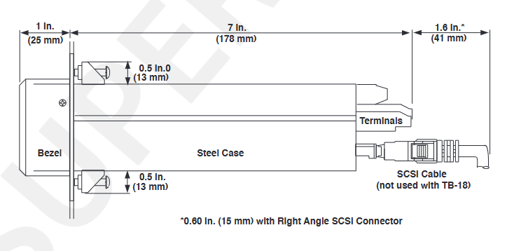
Screw terminals (TB18) 4, 8, 15 outputs (10 can be used for control circuits), 3 inputs with back screw connections, no additional accessories required, suitable for small batch I/O connections
Large scale termination (SCSI) series with 34 outputs, 8 digital inputs+1 pulse input, 50 pin SCSI interface, requires SCSI cable and TB50 terminal board, suitable for multi I/O centralized connection
(2) Analog expansion module
Due to the lack of onboard analog output in the controller, analog signal conversion needs to be achieved through the following modules:
DAC module (digital to analog converter): converts 1-2 distributed zero crossing (DZC) outputs of the controller into analog signals, which can be configured on-site as 4-20mVDC, 0-5VDC, or 0-10VDC.
SDAC module (serial digital to analog converter): converts 1 controller output into high-precision voltage/current signals, supports process variable retransmission, open-loop control, motor/belt speed control, etc., in compliance with CE and UL ®、 C-UL ® Standard.
Key technical parameters
(1) Input performance
Analog input: 4/8 circuit model is differential input, 16 circuit model is single ended input; The maximum common mode voltage is 5V (4/8 circuits), the common mode rejection ratio (CMR) is>60dB (DC to 1kHz), 120dB (selected line frequency), the noise suppression is 120dB (60Hz), and the input overvoltage protection is ± 20V (relative to digital ground).
Thermocouples: Type B (66-1760 ℃, ± 4.0 ℃), Type E (-200-787 ℃, ± 1.0 ℃), etc., with accuracy measured in a 25 ℃ environment (Type B is only valid in the 800-3200 ° F range).
RTD: Only 4/8 circuits are supported, RTD1 (-100-275 ℃, ± 1.1 ℃) and RTD2 (-120-840 ℃, ± 1.6 ℃) require factory pre installed scaling resistors.
(2) Power Supply and Certification
Power requirements: 15-24VDC (± 3VDC), maximum current 1A, no-load current 300mA.
Compliance certification: UL ®、 C-UL ® Certification (compliant with UL) ® 61010-1 standard), CE mark (compliant with EU EMC directive), RoHS design.
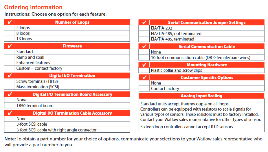
Order Information
The configuration needs to be selected according to the following dimensions, and the final model needs to be confirmed with a Watlow sales representative:
Digital I/O termination method: screw terminal (TB18)/large-scale termination (SCSI).
Accessories: Do you need TB50 terminal board, SCSI cable (3 feet, including optional right angle connector), serial communication cable (10 feet, DB-9 female/bare wire).
Serial communication jumpers: EIA/TIA-232, EIA/TIA-485 (not terminated), EIA/TIA-485 (terminated).
Special Input: If RTD or linear current/voltage input is required, factory pre installed scaling resistors are required (RTD is not supported for 16 circuit models).
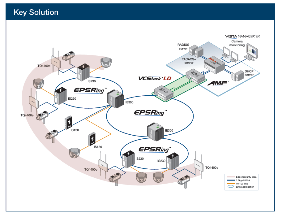
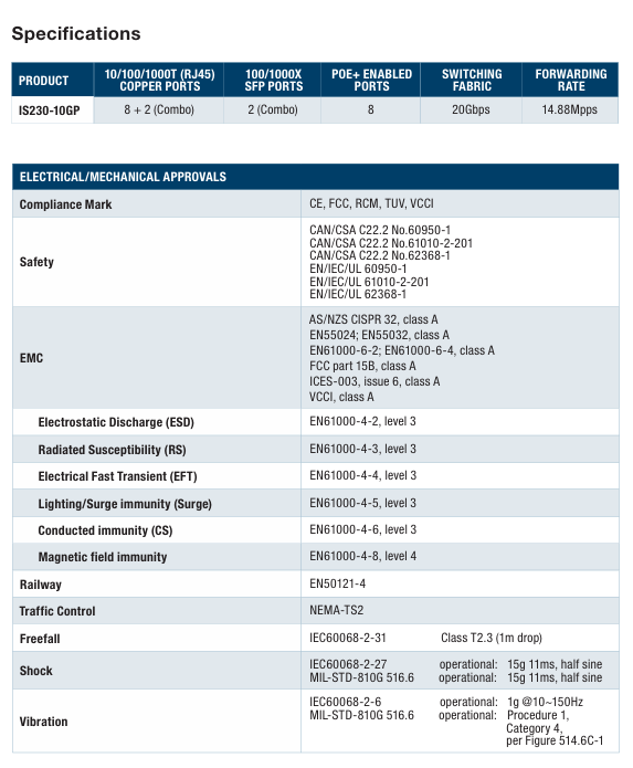
The Allied Telesis IS230 Series is a multipurpose product line of managed Layer 2 switches ideal for industrial applications, including manufacturing, rail transportation (telecommunication and signaling), road transportation (traffic control), and Smart Cities.
With fanless operation and a wide operating temperature range of -40° to 75°C, the robust IS230 Series easily tolerates harsh and demanding environments, such as those found in industrial and outdoor deployments.
An integrated voltage regulator ensures the PoE output voltage always stays at the rated value, regardless of any fluctuations in the input voltage of powered devices. An extended input voltage range makes the IS230 Series ideal for deployment in traffic control cabinets.
Network resiliency
The IS230 Series supports highly stable and reliable ICT network switching, with recovery times down to 50ms. The IS230 can be customized with the most appropriate mechanism and protocol to prevent network connection failure.
Choices include Allied Telesis Ethernet
Protection Switched Ring (EPSRing™), and the standards-based ITU-T G.8032.
Securing the Network Edge
Ensuring data protection means controlling network access. Protocols such as IEEE 802.1X port-based authentication guarantee that only known users are connected to the network. Unknown users who physically connect can be segregated into a pre-determined part of the network. This offers network guests Internet access, while ensuring the integrity of private network data.
Quality of Service
Comprehensive wire-speed QoS provides flow-based traffic management with Port/Tag Base and Type of Service prioritization. Bandwidth control limits ingress/
egress traffic and broadcast/multicast/flooded unicast packets.
Gigabit and Fast Ethernet support
The IS230 Series offers combo ports supporting both Gigabit and Fast Ethernet Small Form-Factor Pluggables (SFPs). Support for both SFP types allows organizations to stay within budget even as they migrate to faster technologies.
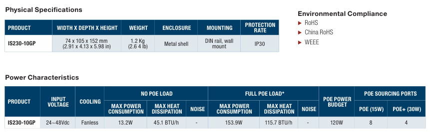
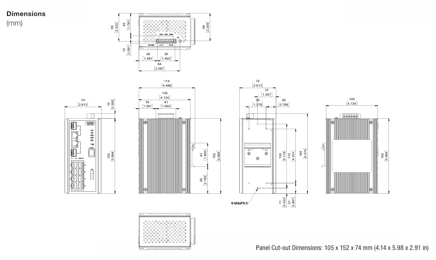
Configurable power budget
On PoE-sourcing IS230 switches, all LAN ports source POE+ up to 30W.
You can configure both the overall power budget and the power feeding limit on a per-port basis, to establish a close relationship between the power sourcing feature and the real capabilities of the external Power Supply Unit (PSU)1.
Dual power inputs
The IS230 Series provides redundant power inputs for higher system reliability; the power inputs are protected against reverse polarity and over-current.
ECO friendly
The IS230 Series are Energy Efficient Ethernet (EEE) devices. They facilitate power saving by switching off parts of the LAN that are not transmitting or recieving data. This sophisticated feature can significantly reduce operating costs, by reducing the
power requirements of the switch and any associated cooling equipment.
Key Features
Full Gigabit, wire speed ports
Uplink combo ports
100/1000Mbps SFP support
Flexible management interface (GUI, SNMP, CLI, TELNET and SSH)
Ethernet Protection Switched Ring (EPSRing™)
Ethernet Ring Protection Switching (ITU-T G.8032)
VLAN stacking (Q-in-Q)
Multicast support (IGMP and MLD snooping)
Loopback detection and storm control
Port mirroring
Port trunking/link aggregation (LACP)
Link Layer Discovery (LLDP)
IEEE 802.3at PoE+ sourcing (30W)
-40 to +75oC wide-range operating temperature
Dual power inputs with voltage boost converter
Alarm output
Fanless design
Performance
Up to 8K MAC addresses
Packet buffer memory: 512KB (4Mb)
8 priority QoS queues
4094 configurable VLANs
256 simultaneous VLANs
Supports 9KB jumbo frames
Up to 255 Layer 2 multicast entries
Environmental Specifications
Operating temperature range: -40°C to 75°C (-40°F to 167°F)
Storage temperature range: -40°C to 85°C (-40°F to 185°F)
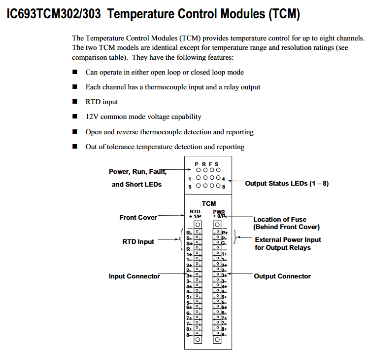
The functional framework of the two TCM modules is consistent, with only differences in temperature range and resolution. The core capabilities include:
Control mode: Supports two operating modes: Open Loop and Closed Loop, suitable for different temperature control scenarios.
Channel configuration: It can achieve temperature control for up to 8 channels, each equipped with thermocouple input interface and relay output interface, and supports RTD (resistance temperature detector) input.
Voltage compatibility: Equipped with 12V common mode voltage capability, suitable for signal transmission needs in industrial scenarios.
Fault detection: supports automatic detection and reporting of two types of critical faults——
Thermocouple faults: including open circuit (Open) and reverse circuit (Reverse) faults;
Temperature anomaly: Detect and report temperature deviations that exceed the tolerance range.
Hardware Connection and Interface Description
The module is connected to external devices through two pairs of matching “plug-in connectors” with captive screw terminals for easy on-site wiring. The specific interface division is as follows:
Input connector module left thermocouple (8 channels, corresponding to 1+-1- to 8+-8- terminals), RTD (R+, R -, S+, S – terminals) – Channel input: 1+-1- to 8+-8- (each channel’s positive and negative terminals correspond to a thermocouple)
-RTD inputs: R+, R -, S+, S – (compatible with RTD sensors)
Output connector module right side relay (8 channels, corresponding to 1+-1- to 8+-8- terminals), external power supply (P+, P – terminals) – channel output: 1+-1-~8+-8- (each channel positive and negative terminal corresponds to a relay)
-External power supply: P+(positive pole), P – (negative pole, supplying power to the output relay)
-Grounding: G terminal (grounding connection)
In addition, there is an internal fuse located behind the front cover of the module for circuit overload protection. The specific parameters are “2 Amp, 125V ultra small fuse” (recommended model: Littlefuse Microfiuse 273 002 or equivalent).
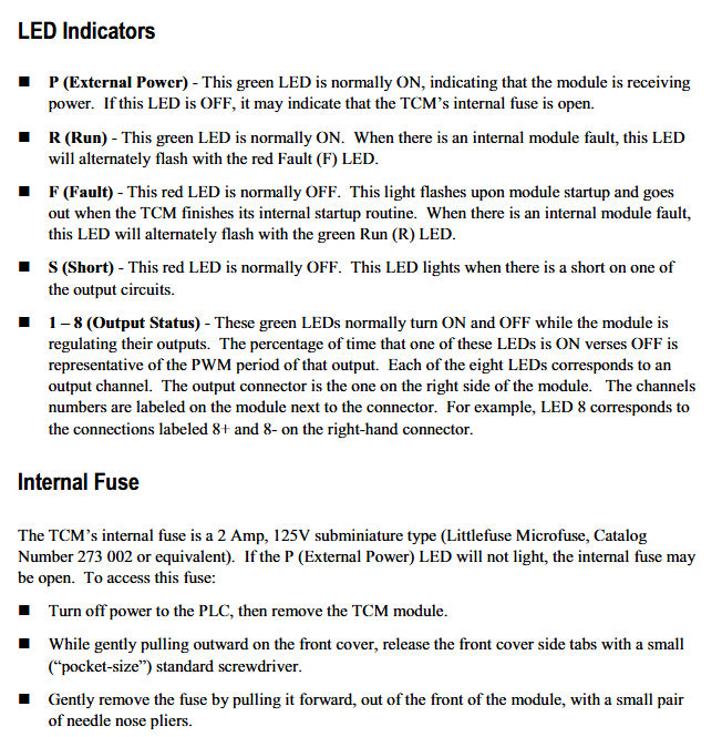
Meaning of LED status indicator light
The front of the module is equipped with 6 types of LED indicator lights, which provide feedback on device operation and fault information through on/off/flashing status. The specific instructions are as follows:
Meaning and Status Explanation of LED Identification Colors
P (External Power) green – normal state: constantly on, indicating that the module has been connected to an external power source;
-Abnormal state: Off, possibly due to a blown internal fuse.
R (Run) green – normal status: constantly on, indicating that the module is running normally;
-Abnormal state: The red F (Fault) LED flashes alternately, indicating an internal fault in the module.
-Abnormal state: The green R (Run) LED flashes alternately, indicating an internal fault in the module.
S (Short) red – normal state: normally off;
-Abnormal state: illuminated, indicating a short circuit fault in one of the output circuits.
1-8 (Output Status) Green – Function: Corresponding to 8 output channels, the indicator light on/off ratio reflects the PWM (Pulse Width Modulation) cycle of that channel;
-Example: LED 8 corresponds to the channel to which the 8+and 8- terminals of the right connector belong, and the on/off rhythm is synchronized with the channel output adjustment.
Automatic data exchange with PLC
The module and the CPU of Series 90-30 PLC achieve control and status feedback through “automatic data transmission”, without the need for manual triggering. Each PLC sweep completes a data exchange, and the specific data flow is as follows:
1. PLC → TCM (Control Instruction Transmission)
PLC sends control instructions to TCM through% Q bit (digital output) and% AQ word (analog output), and the core instructions include:
Alarm Limit Values (temperature alarm upper and lower limits) transmission.
2. TCM → PLC (status information feedback)
TCM provides feedback on the operating status to PLC through the% I bit (digital input) and% AI word (analog input), with core information including:
Alarm status (such as over temperature alarm);
Output Short Circuit status;
Current Temperature (real-time temperature of each channel);
PWM period (the pulse period output by each channel);
TCM Error Code (locate specific fault type).
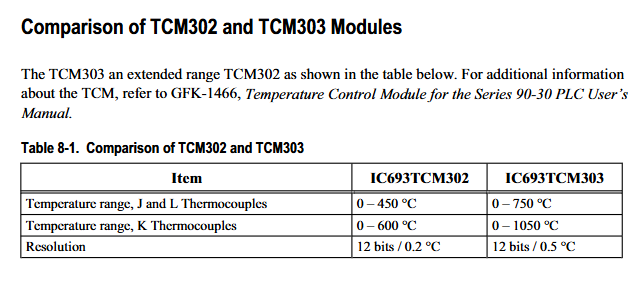
Core differences between TCM302 and TCM303
The two modules only differ in “temperature measurement range” and “resolution”. TCM303 is the “extended range version”, and the specific parameter comparison is as follows:
Comparison item IC693TCM302 IC693TCM303
J-type and L-type thermocouples have a temperature range of 0-450 ° C to 0-750 ° C
K-type thermocouple temperature range 0-600 ° C 0-1050 ° C
Resolution 12 bits/0.2 ° C (i.e. minimum temperature detection accuracy of 0.2 ℃) 12 bits/0.5 ° C (i.e. minimum temperature detection accuracy of 0.5 ℃)
Precautions for replacing fuses
When the P (External Power) LED goes out and the fuse is suspected to be blown, the following steps must be followed to replace it, and safety regulations must be followed:
Turn off the PLC power first, and then remove the TCM module;
Use a small standard screwdriver (pocket size) to loosen the side card of the front cover and gently pull the cover outward;
Use pointed nose pliers to pull out the old fuse from the front of the module and replace it with a fuse of the same specification (2A, 125V);
Warning: It is strictly prohibited to use fuses that do not meet the specifications, otherwise it may cause personal injury or equipment damage.
Product model: 979B (atmospheric pressure to vacuum sensor), part number 100014647
Safety and General Specifications
1. Safety warnings and preventive measures
Electrical safety: When replacing sensors or baking, the power supply must be disconnected first (there may be fatal voltage/current), and only qualified technicians can operate electronic components; Use+24 VDC@0.75 Amps power supply, ensure that the sensor is grounded through the vacuum flange and electrical connector rear housing.
Operation restriction: Do not turn on the filament power supply when the system pressure is higher than 5 × 10 ⁻ Torr (which may damage the hot cathode sensor); Prohibited from use in explosive/flammable gas environments (hot cathode heating elements, MicroPirani’s nickel film elements may ignite gases); Do not replace parts or modify equipment. Repairs must be sent to the MKS calibration service center.
Pollution protection: prevent dust, metal shavings and other pollutants from entering the equipment; During installation, stay away from electronic/ion sources and strong magnetic fields. If necessary, use a particulate filter (see “Accessories” section for details).
2. General technical specifications
Specific project parameters
Measurement range 5 × 10 ⁻¹⁰ Torr to atmospheric pressure (ATM)
Set point range 5 × 10 ⁻¹⁰ Torr to 100 Torr
Analog output DAC1: 0.5-6.95 VDC (0.5 V/order of magnitude); DAC2: 0.75-10.02 VDC (0.75 V/order of magnitude)
Location selection: It is necessary to be able to accurately measure the pressure in the vacuum chamber, away from the pump and gas source to ensure representative readings; Avoid installing directly above the evaporation source (steam may contaminate the sensor), and shield and stay away from strong magnetic fields when approaching electronic/ion sources.
Installation direction: Supports installation in any direction, it is recommended that the vacuum port face downwards (to prevent particles/liquids from entering), which does not affect measurement accuracy.
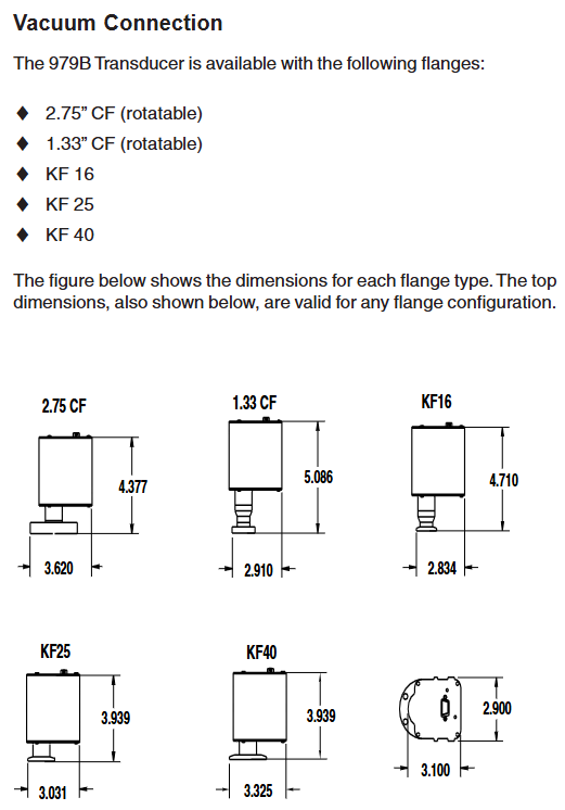
2. Vacuum connection
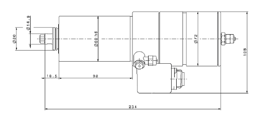
The sensor offers multiple flange types: 2.75 “CF (rotatable), 1.33” CF (rotatable) KF16、KF25、KF40, Corresponding flanges need to be matched according to the system, and the manual provides dimension drawings of each flange for reference.
3. Electrical connection
Cable requirements: Use a 15 pin high-density D-sub female cable with strain relief; To meet the anti-interference requirements of EN61326-1, braided shielded cables are required, with metal hooks connected at both ends of the shielding layer and the power supply grounded.
Pin function: The 15 pin D-sub connector has clear pin division, and the core pins include: 1 pin (RS485-/RS232 TXD), 2 pins (RS485+/RS232 RXD), 3 pins (power+24V), 4 pins (power -), 5 pins (analog output+), 6 pins (analog output -), 9 pins (degassing state), 10 pins (filament selection), 13 pins (degassing on), as well as the common terminals (7, 11, 14 pins) and normal terminals (8, 12, 15 pins) of 3 relays. For details, please refer to the “979B Sensor Electrical Connection Table”.
Attention: The negative terminal (6-pin) of the analog output should not be connected to the negative terminal (4-pin) of the power supply or other grounding points (which may cause current diversion and measurement errors, and the longer the cable, the greater the error); When connecting inductive loads (such as solenoids and transformers), an arc extinguishing network (resistor R and capacitor C) needs to be installed. The calculation formula is
C=I 2/(1 × 10 7) (Farads), R=E/I a (ohms, where a=1+(50/E)), and R is at least 0.5 Ω and C is at least 1.0 × 10 ⁻⁹ F.
Operation control
1. Control and status pin operation
Degassing on (Pin13): Enable degassing when grounded, with priority higher than DG command or degassing button; After 30 minutes of degassing, it is necessary to disconnect and reconnect to restart degassing, and degassing should not exceed 30 minutes every 4 hours.
Degassing state (Pin9): When degassing is closed, it is open circuit/suspended, and when it is open, it is grounded; An external pull-up resistor with ≤ 24 VDC can be connected, and the current should be less than 15mA.
Filament selection (Pin10): By switching the active filament on/off the power supply, the state can be switched instead of selecting a fixed filament.
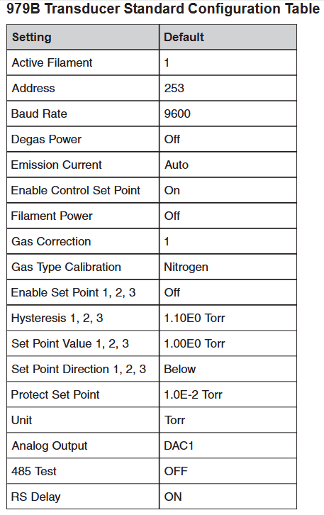
2. Factory default settings
The sensor parameters are preset to default values, including: active filament 1, address 253, baud rate 9600, degassing power off, automatic emission current (20 μ A>1 × 10 ⁻⁴ Torr, 1mA<1 × 10 ⁻⁴ Torr), control set point enabled, filament power off, gas correction 1, gas calibration type nitrogen, 3 set points disabled, hysteresis value 1.10E0 Torr, set point value 1.00E0 Torr, set point direction “below (BELOW)”, protection set point 1.0E-2 Torr, unit Torr, analog output DAC1, RS485 test off, RS delay on.
3. RS-485/RS-232 communication protocol
Basic parameters: Supports baud rates of 4800-112200 (default 9600), data format of 8-bit data bits, no checksum, and 1-bit stop bit; RS-485 is a half duplex two-wire system, which is the same protocol as RS-232.
Address rule: Standard address 001-253 (default 253); Universal address 254 (used for communication with unknown address devices, will respond), 255 (broadcast address, executes commands but does not respond, such as batch modification of baud rate).
Command syntax: The query format is @<device address><query command>?; FF (such as querying baud rate: @ 253BR?)?; FF), The command format is @<device address><command instruction>! <Parameters>; FF (such as changing the baud rate to 19200: @ 253BR! 19200; FF); The response starts with ACK (success) or NAK (failure), and the NAK code corresponds to different errors (such as 160=unrecognized message, 169=invalid parameter, 172=value out of range, etc.).
4. Core Command Set
The commands are divided into five categories: setting, status, pressure measurement and degassing, set point, and calibration. The core commands are as follows:
Command Type Command Identification Function Description Example
Set command AF (active filament) to query/select 2 filaments (value 1/2) of the hot cathode sensor. Query: @ 001AF?; FF; Setting: @ 001AF! 2; FF
DAC (Analog Output) Query/Set Analog Output Type (1=DAC1, 2=DAC2) Query: @ 001DAC?; FF; Setting: @ 001DAC! 2;FF
FD (factory default) restores all user calibration values to factory default command: @ 001FD!; FF
Status command DT (device type) query device type response: @ 001ACKMP-HC 979B; FF
FS (filament status) query for the on/off status of the active filament: @ 001FS?; FF
FV (firmware version) query firmware version response: @ 001ACK1.00; FF
SN (serial number) query device serial number response: @ 001ACK0000012345; FF
T (sensor status) query hot cathode status (F=filament fault, G=hot cathode on, etc.) Response: @ 001ACKO; FF (O=normal)
Pressure measurement and degassing FP (filament power supply) switch filament power supply (only effective when the control setpoint is disabled, disabled when the pressure is greater than 5 × 10 ⁻ Torr) command: @ 001FP! ON; FF
DG (degassing power supply) switch degassing (pressure must be<1 × 10 ⁻⁵ Torr, automatically shuts off after 30 minutes) query: @ 001DG?; FF; Setting: @ 001DG! ON; FF
Calibration command ATM (atmospheric pressure calibration) to calibrate MicroPirani to full range (requires ventilation to atmospheric pressure, stable for 20 minutes) Command: @ 001ATM! 7.60E+2; FF
VAC (vacuum calibration) calibration MicroPirani zero point (needs to be drawn to<1 × 10 ⁻⁴ Torr, stabilized for 20 minutes, automatically calibrated when hot cathode pressure<1 × 10 ⁻⁴ Torr) command: @ 001VAC!; FF
GC (gas correction) query/set gas correction coefficient for hot cathode (0.10-50.1, default 1, such as argon 1.29) setting: @ 001GC! 1.29; FF
Analog output and gas correction
1. Simulation output calculation and table
DAC1: Pressure calculation formula P=10 (2V − 11) (Torr), the manual provides a detailed voltage correspondence table for 1.0E-10 Torr (0.50V) to 1.0E+03 Torr (7.00V).
DAC2: Pressure calculation formula P=10 0.75 V − 7.75 (Torr), also provide a complete pressure voltage correspondence table.
2. Gas correction factor
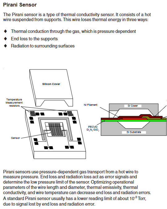
MicroPirani is based on gas thermal conductivity measurement, and the hot cathode is based on gas ionization measurement, both of which need to be corrected according to the gas type:
Gas chemical formula gas correction factor (GC)
Air -1.00
Argon gas Ar 1.29
Carbon dioxide CO ₂ 1.24
Deuterium gas D ₂ 0.35
Helium He 0.18
Hydrogen H ₂ 0.46
Krypton gas Kr 1.94
Neon gas Ne 0.30
Nitrogen N ₂ 1.00
Nitric oxide NO 1.16
Oxygen O ₂ 1.01
Sulfur hexafluoride SF ₆ 2.50
Water H ₂ O 1.12
Xenon Xe 2.87
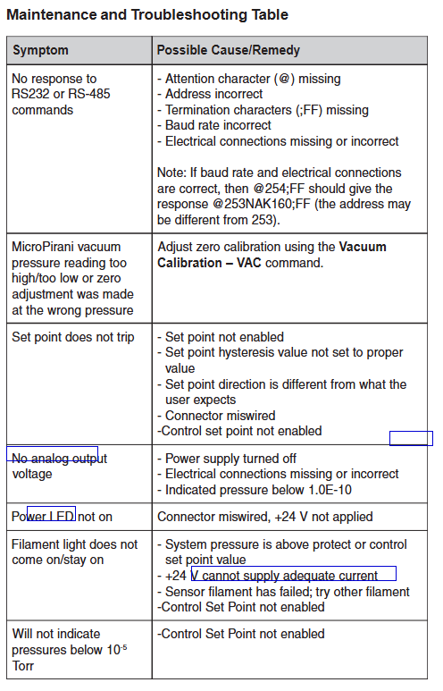
Maintenance and troubleshooting
1. Daily maintenance
Cleaning: The casing can be cleaned with water or alcohol to prevent liquids from entering the electronic casing; The sensor tube must not be cleaned (as it may damage the components), and the sensor needs to be replaced in case of severe contamination.
Degassing operation: When the hot cathode sensor is contaminated by process gas (especially when the sensitivity drifts when the pressure is ≤ 10 ⁻⁸ Torr), regular degassing is required; When degassing, the pressure should be less than 1 × 10 ⁻⁵ Torr. During this period, the pressure can be measured but the reading may be higher than the system pressure. When the pressure is greater than 1 × 10 ⁻⁴ Torr, degassing is paused and restarted after reaching the threshold. It will automatically terminate after 30 minutes, and degassing should not exceed 30 minutes every 4 hours.
2. Common faults and solutions
Possible causes/solutions for the fault phenomenon
Product core positioning and application scenarios
1. Core positioning
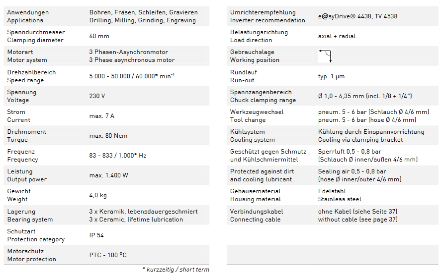
The 4061 motor spindle is a high-speed precision spindle driven by three-phase asynchronous drive. It adopts an integrated design, integrating the motor, bearings, clamping system, and protective structure. It is suitable for industrial processing scenarios with strict requirements for speed and accuracy. It can be directly mounted on machine tools or automation equipment to achieve efficient cutting and forming of workpieces.
Applicable industries: precision machinery manufacturing, electronic component processing, mold manufacturing, medical device parts processing, etc;
Suitable for workpieces: small and medium-sized precision parts such as metal, non-metal (such as plastic, composite materials), etc.
Key technical parameters
1. Basic performance parameters
Parameter category, specific specifications, remarks
Clamp diameter (Spandurchmesser) 60mm is used to fix the connection size between the spindle and the equipment
Motorart: A mature and stable driving method for three-phase asynchronous motors, suitable for industrial inverters
Speed range (Drehzahlbereich) 5000-50000 min ⁻¹ (conventional); 60000 min ⁻¹ (short-term) High speed is suitable for temporary high-intensity processing, and attention should be paid to the load duration
Power supply parameter voltage (Spanung): 230V; Current (Strom): maximum 7A; Frequency: 83-833Hz (conventional), 1000Hz (short-term). The frequency is positively correlated with the speed and needs to be adjusted with an adaptive inverter
Maximum torque output performance (Drehmomont): 80Ncm; Maximum power (Leistung): 1400W to meet the power requirements of medium and light precision machining
The precision index (Rundlauf) has a typical value of 1 μ m and high rotational accuracy, ensuring smooth surface and precise size of the processed workpiece
2. Structure and protection parameters
Specific specifications and functions of parameter categories
Lagerung bearing system consists of 3 sets of ceramic bearings (3 x Keramik) with lifetime lubrication (lebensdauergeschmiert). Ceramic bearings have strong wear resistance and low heat generation, extending the life of the spindle without the need for regular oil replenishment
Protection level (Schutzart) IP54 dustproof (completely preventing dust intrusion), splash proof (no damage from splashing in any direction), suitable for workshop processing environment
Motor protection (Motorschutz) PTC temperature protection (triggered at 100 ℃) automatically protects when the motor temperature exceeds 100 ℃ to prevent overheating and damage
The shell material (Geh ä usematerial) is made of stainless steel (Edelstahl), which is corrosion-resistant and impact resistant, suitable for long-term exposure to cutting fluids or dust
Anti pollution design seal gas protection (Sperrlft): 0.5-0.8 bar, compatible with 4/6mm inner and outer diameter hoses to prevent dust and cooling lubricants from entering the spindle during processing, protecting bearings and motors
3. Clamping and cooling parameters
Specific specifications and details of parameter categories
The clamping range of the chuck (Spanzangenbereich) is Ø 1.0-6.35mm (including standard specifications of 1/8 inch and 1/4 inch), suitable for common specifications of cutting tools (such as milling cutters and drill bits), meeting the needs of multi scene machining
Tool Replacement (Werkzeugwechsel) Pneumatic Drive (Pneum.), pressure 5-6 bar, compatible with 4/6mm flexible hose for quick automatic tool change, improving machining efficiency and reducing manual intervention
The cooling system (K ü hlsystem) is cooled by a clamping bracket (K ü hlung durch Einspannvorrichtung) using the device’s own clamping structure to conduct heat, without the need for additional cooling fans or water cooling devices, simplifying the structure
Supporting requirements and installation instructions
1. Essential supporting equipment
Inverter (Umrichter): Recommended model is e @ syDrive ® 4438 TV 4538, Need to match the voltage and frequency range of the spindle to adjust the speed and output power;
Pneumatic system: Tool replacement requires 5-6 bar compressed air, anti pollution requires 0.5-0.8 bar sealed air, and the air source must be stable, oil-free, and water free;
Connecting cables: The product does not include cables. Please refer to page 37 of the document to select the appropriate specifications (such as wire diameter and insulation level) to ensure stable and safe power supply.
2. Installation and usage restrictions
Load direction (Belastungsrichtung): Supports axial and radial loads, can withstand multi-directional machining forces, but needs to avoid overloading operations beyond the torque/power limit;
Work position (Gebrauchslab): No special restrictions, can be flexibly installed according to equipment layout (such as horizontal, vertical, inclined);
Maintenance requirements: The bearings are designed for lifelong lubrication and do not require regular maintenance; Regularly check the sealing gas pressure and clamp clamping accuracy to prevent machining quality from being affected by insufficient air pressure or clamp wear.
DeltaV electronic grouping is a “flexible I/O architecture” technology that replaces traditional hard wired terminal cabinets with CHARactration Modules and Electronic Marshalling Cabinets to achieve a “soft connection” between field device signals (analog/digital input/output) and DeltaV controllers – without the need to lay a large number of field cables, signal routing can be allocated through configuration software, and the core service is for the migration scenario of old DCS systems.
2. Core migration value
Compared to the traditional migration model of “dismantling old systems and rebuilding new systems”, the core advantages of this solution are reflected in the three dimensions of “cost reduction, risk reduction, and efficiency improvement”:
Reduce downtime: Support “parallel migration” – while the old system is running normally, complete the installation, configuration, and testing of the new system’s electronic grouping architecture, with only a brief shutdown at the final switch (usually in hours, rather than days/weeks of traditional migration).
Reduce hardware and wiring costs: eliminate the need for replacing/laying a large number of on-site cables in traditional migration (especially suitable for large factories, where on-site equipment is far away from control rooms); The electronic grouping cabinet has a smaller volume, reducing the footprint of the control room.
Enhance system flexibility and maintainability: Signal routing is implemented through software configuration, and there is no need to rewire when adding/modifying devices in the future; The CHAR module supports online hot plugging, and fault replacement does not affect other signals; Integrated diagnostic function can quickly locate signal faults (such as disconnection and short circuit).
Compatible with legacy devices: No need to replace existing sensors and actuators on site (such as 4-20mA analog devices and discrete digital devices), directly adapt to old device signal types, and protect early investment.
Core components and technical parameters
1. Core hardware components
The hardware architecture of the DeltaV electronic grouping solution consists of three parts: “field side grouping side controller side”. The core components and functions are as follows:
Component Name Model/Specification Core Functions Key Features
The CHAR module (signal interface module) is divided into analog (AI/AO), digital (DI/DO), and special signal (such as RTD, thermocouple) series, such as:
-AI module: supports 4-20mA, 0-10V, etc
-DI module: supports the “conversion interface” between 24Vdc, 120Vac discrete signal field equipment signals and DeltaV systems, realizing signal acquisition/output, isolation, and filtering. 1. Channel level isolation (each channel is independently isolated to prevent interference);
2. Online hot plugging (replacing modules without interrupting system operation);
3. Built in diagnostics (monitoring channel faults, module power supply abnormalities);
4. Protection level IP20 (applicable to control room/cabinet environment)
Electronic grouping cabinet standard 19 inch rack mounted, height optional (such as 42U, 36U), including power module, backplane, integrated CHAR module for heat dissipation unit, power distribution, signal aggregation function, replacing traditional hard wired terminal cabinet. 1. Modular design (configure the number of CHAR modules as needed);
2. Redundant power supply (optional 2 × 24Vdc redundant power supply, anti power failure);
3. Backplane bus (supporting data communication and power supply between modules);
4. Heat dissipation control (built-in fan or natural heat dissipation, suitable for industrial environments)
DeltaV S series controllers (such as S100, S200) receive signal data from electronic grouping modules, execute control logic (such as PID regulation, interlock control), and output control instructions to the site. 1. Redundant configuration (optional controller redundancy to improve reliability);
2. High speed communication (communication with electronic grouping cabinets through EtherNet/IP, cycle ≤ 10ms);
3. Compatible with DeltaV V14 and above software versions
On site wiring terminal box (optional) explosion-proof type (such as Ex d) or ordinary type, used for summarizing and transferring cables of on-site equipment. When the on-site equipment is scattered, the cables are first summarized in the terminal box and then connected to the electronic grouping cabinet through a “backbone cable” to reduce wiring volume. 1. Support mixed access of multiple signal types;
2. Explosion proof models are suitable for hazardous areas (such as Class I, Div 1/2)
2. Key technical parameters (general)
Signal compatibility:
Analog input (AI): 4-20mA (two-wire/four wire system), 0-5V, 0-10V, RTD (Pt100, Cu100), thermocouple (J, K, T, E, R, S type);
Analog output (AO): 4-20mA (sourcing/linking), 0-10V;
Digital input (DI): 24Vdc (wet/dry contact), 120Vac, 230Vac;
Digital output (DO): 24Vdc (maximum 0.5A/channel), relay output (250Vac/5A).
Communication protocol: EtherNet/IP protocol is used between the electronic grouping cabinet and the controller, supporting high-speed data transmission (communication rate 100Mbps full duplex); The module adopts DeltaV dedicated backplane bus internally.
Power requirements: The power supply for the electronic grouping cabinet is 24Vdc (± 10%), and the maximum power consumption of a single cabinet depends on the number of modules (typical value: power consumption of each CHAR module ≤ 5W).
Environmental conditions:
Working temperature: 0 ℃~55 ℃ (cabinet environment);
Storage temperature: -40 ℃~70 ℃;
Relative humidity: 5%~95% (without condensation);
Anti electromagnetic interference: Complies with EN 61000-6-2 (industrial environment immunity) standard.
Security certification:
Electrical safety: UL 61010-1, CSA C22.2 No. 61010-1;
Electromagnetic compatibility (EMC): EN 61326-1 (industrial environment);
Hazardous area certification (some components): ATEX, IECEx (applicable to Zone 2/Class I, Div 2).
Migration process and applicable scenarios
1. Standard migration process
The DeltaV electronic grouping migration follows a “four stage” implementation framework to ensure parallel operation and smooth switching with the old system:
Planning and Evaluation Stage
Evaluate the I/O signal types, quantities, cable routing, and control logic of old systems such as RS3 and WDPF;
Determine the number and installation location of electronic grouping cabinets (usually near old terminal cabinets to reduce cable modifications);
Develop a migration schedule (distinguishing between “non critical circuits” and “critical circuits”, prioritizing the migration of non critical circuits).
Installation and configuration phase
Install electronic grouping cabinets, CHAR modules, and on-site wiring terminal boxes (if necessary) while the old system is running normally;
Connect the on-site cable to the CHAR module (without disconnecting the old system wiring, dual system signal acquisition can be achieved through “T-shaped wiring” or parallel wiring);
Configure signal routing in DeltaV software (mapping CHAR module channels to DeltaV controller I/O points) and import old system control logic (supporting logic conversion tools).
Testing and Verification Phase
Conduct offline testing on the migrated circuit (simulate on-site signals to verify the correctness of control logic);
Conduct online parallel testing (both the old and new systems receive on-site signals simultaneously, compare the output results, and ensure consistency);
Perform multiple rounds of validation on critical circuits such as emergency shutdown system ESD and reactor temperature control to ensure no deviation.
Switching and optimization phase
Select non peak production hours to “switch” a single circuit or area (disconnect the old system wiring and be controlled separately by the new system);
Continuously monitor the operating status of the system after switching, and use DeltaV diagnostic function to identify potential faults;
After completing the full system migration, dismantle the old system hardware and optimize the new system parameters (such as control algorithms and alarm thresholds).
2. Applicable migration scenarios
This solution is not applicable to all DCS migrations, and the core matches the following scenarios:
The old system is a hard wired DCS, such as Fisher Rosemount RS3, Westinghouse WDPF, Honeywell TDC 3000 and other old systems without flexible I/O architecture;
Industries with high downtime costs, such as refining, ethylene, LNG, and other continuous production processes, can experience significant economic losses due to long downtime caused by traditional migration;
The on-site equipment is in good condition: the on-site sensors and actuators are still within their service life and do not need to be replaced (if the equipment has aged, it can be implemented synchronously with “equipment update+electronic grouping migration”);
Limited space in the control room: The electronic grouping cabinet has a smaller volume and is suitable for scenarios where there is insufficient expansion space in the control room.
Not applicable scenario: The old system is a fully digital architecture (such as systems that have already adopted Profinet and Foundation Fieldbus); All on-site equipment needs to be replaced (it is more economical to directly use the new DeltaV system at this time).
System advantages and competitive differences
1. Core advantages (vs traditional migration)
Comparison Dimension DeltaV Electronic Grouping Migration Traditional Hardwired Migration
Short downtime (hourly level, only shutdown during switching stages) Long downtime (several days/weeks, complete system dismantling and reconstruction)
Low wiring cost (no need to re lay on-site cables, only need to connect between cabinets) High (all on-site cables need to be replaced, especially long-distance circuits)
High flexibility (software configuration signal routing, no wiring required for subsequent changes) Low flexibility (fixed hardware wiring, rewiring required for changes)
Low risk control (parallel operation, phased migration, can be rolled back to the old system at any time) High (one-time switching, no rollback path for faults)
Low maintenance cost (module hot plugging, integrated diagnosis, fast fault location) and high (complex troubleshooting of hard wired faults, requiring point by point testing)
2. Differences from other electronic grouping schemes
Compared to competitors such as Rockwell PlantPAx electronic grouping and Siemens PCS 7 Distributed I/O, the uniqueness of the DeltaV solution lies in:
Deep integration of DeltaV ecosystem: The CHAR module is seamlessly compatible with DeltaV controllers and software (such as DeltaV Operate and DeltaV Explorer), without the need for third-party adaptation tools;
Strong adaptability of legacy system: providing dedicated migration tools for Emerson’s old systems (such as RS3), which can automatically convert control logic and I/O databases, reducing manual configuration workload;
More comprehensive diagnostic functions: The CHAR module supports “channel level fault diagnosis” (such as disconnection, overcurrent, signal drift), and uploads diagnostic information in real time to the DeltaV alarm system without on-site inspection.
Purpose: Used for the “on-off” control and fail safe (power-off spring reset) operation of air doors and valves in HVAC systems, supporting direct coupling installation, and some models can be connected in parallel (linkage installation) to meet high torque requirements.
Key feature: Mechanical spring reset (clockwise/counterclockwise optional), ensuring reliable reset after power loss; 95 ° rotation stroke (can be limited by accessories to 30 ° -95 °); Visual position indicator; Overload protection during full rotation process; Some models come with built-in auxiliary switches for signal interaction or interlock control.
2. Differences in Series Models
The three major series are distinguished by torque level, voltage specifications, and additional functions, with the following core differences:
Series torque levels (lb in/N-m) voltage specifications core features auxiliary switch configuration manual override function
MA40-704X 35 (4) 24Vac/DC, 120Vac, 230Vac NEMA 2/IP54 protection (no installation restrictions), travel limiter standard with some models (-501) including 1 SPDT switch (0-95 ° adjustable) none
MA4X-707X 60 (7) 24Vac/DC, 120Vac, 230Vac NEMA 2/IP54 protection (requires downward installation of conduit), supports rotation restriction part models (-502) including 2 SPDT switches (1 fixed at 5 °, 1 adjustable at 25-85 °) MA41-707X series has (-5 ° to 85 ° adjustable)
MA4X-715X 133 (15) 24Vac/DC, 120Vac, 230Vac, same as MA4X-707X, with maximum torque, can be installed in parallel with two machines. Some models (-502) include two SPDT switches (one fixed at 5 ° and one adjustable at 25-85 °). The MA41-715X series has (-5 ° to 85 ° adjustable)
MA41-7153-502 Exclusive Attributes: Belonging to the MA4X-715X series, powered by 24Vac/DC, 133lb in (15N-m) torque, including 2 SPDT auxiliary switches, with manual override function, supporting dual machine parallel connection.
Key technical parameters
1. Electrical parameters
Specific specifications for parameter categories (taking MA41-7153-502 as an example, refer to Table 1 for other models)
Supply voltage 24Vac ± 20% or 22-30Vdc
Power consumption operation: 9.8VA (50Hz), 9.7VA (60Hz); Maintain: 7.5VA (50/60Hz)
Current running DC current 0.29A; locked rotor current 2.8A
Rotation stroke: Maximum 95 °± 5 °, MA40-704X series comes standard with a travel limiter, MA4X-707X/715X requires AM-689 accessories to achieve 30 ° -95 ° adjustment.
Wind door shaft adaptation:
MA40-704X: Standard fixture supports ≤ 5/8 inch (15mm) circular axis or ≤ 1/2 inch (13mm) square axis; AM-710 accessories support ≤ 3/4 inch (19mm) circular shafts.
MA4X-707X/715X: Standard fixture supports ≤ 3/4 inch (19mm) circular axis or ≤ 1/2 inch (13mm) square axis; AM-687 accessories support circular shafts ≤ 1.05 inches (27mm) or square shafts ≤ 5/8 inches (15mm).
Protection level: MA40-704X is NEMA 2/IP54; MA4X-707X/715X is NEMA 1/IP30 (NEMA 2/IP54 when the conduit is facing downwards).
Environmental conditions: Operating temperature -22 ° F to 140 ° F (-30 ° C to 60 ° C); Storage/transportation temperature -40 ° F to 160 ° F (-40 ° C to 71 ° C); Humidity 15% -95% RH (non condensing).
Certification: UL 873, CUL (Canada), CE (compliant with EMC/Low Voltage Directive), C-Tick Australia.
Installation specifications and operating procedures
1. Preparation before installation
Personnel requirements: It must be operated by qualified professional technicians who are familiar with national/local electrical regulations.
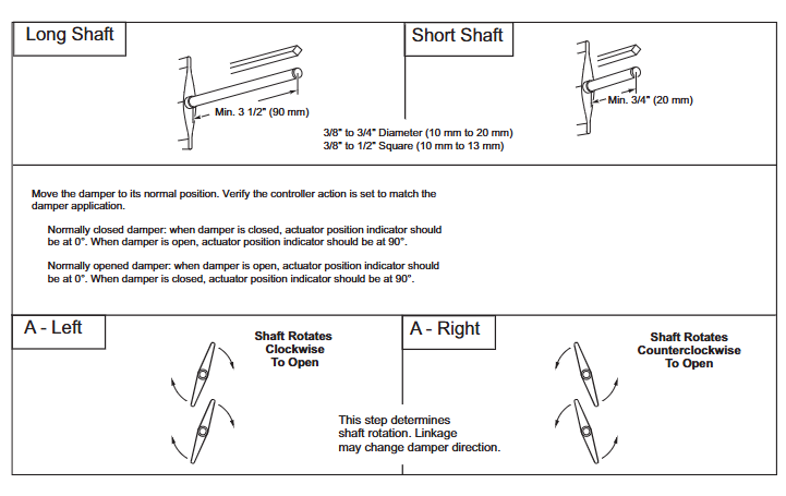
Tools and accessories: Please bring your own # 8 sheet metal screws, 10mm wrench, 7/16 inch wrench, 1/8 inch hex wrench, and screwdriver; Select the corresponding fixture based on the shaft diameter (such as AM-710, AM-687), and the installation method for the long axis (≥ 3.5 inches/90mm) and short axis (<3.5 inches/90mm) is different.
Safety warning: Disconnect the power supply before installation to prevent electric shock; Avoid approaching strong electromagnetic interference sources such as contactors and large motors; It is prohibited to drill holes in the actuator body (there are 6 pre drilled holes under the labels on both sides for accessory installation).
2. Core installation steps (divided into series)
(1) MA40-704X series
Wind door positioning: Adjust the wind door to the normal position (the indicator indicates 0 ° when the normally closed wind door is closed, and 0 ° when the normally open wind door is open), and confirm the direction of shaft rotation (clockwise/counterclockwise opening).
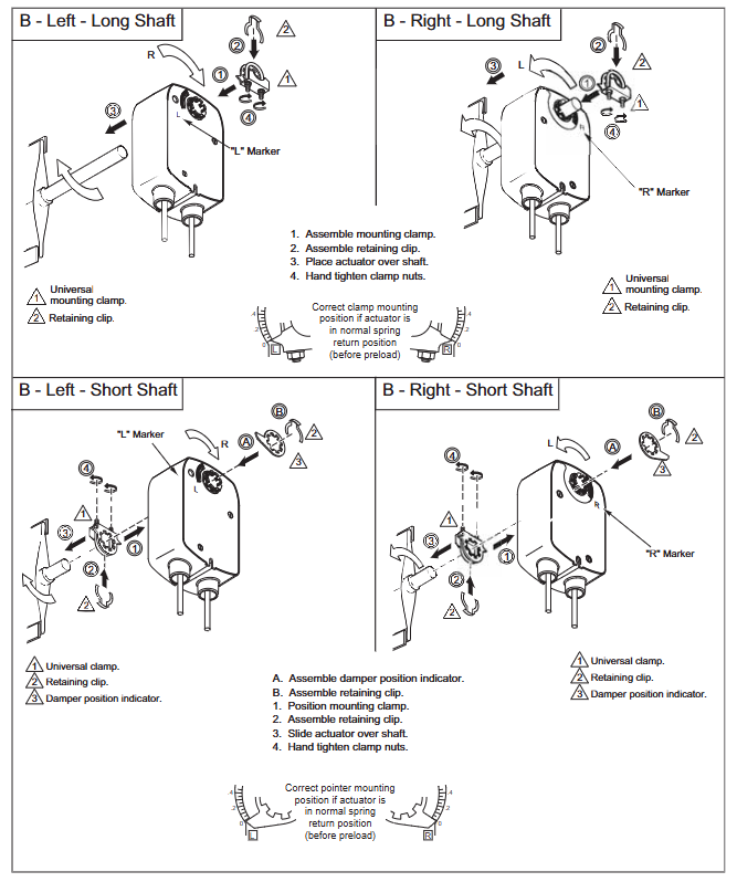
Fixture installation: For short shafts (<3.5 inches), the air door position indicator should be installed first, then the actuator should be inserted and the fixture nut should be manually tightened; Insert the long axis directly into the actuator and manually pre tighten the fixture.
Fixing and Calibration: After aligning the centerline, drill a hole to fix the bracket, loosen the clamp nut, rotate the actuator 5 ° in the direction of operation (without moving the shaft), then tighten the clamp nut with a torque of 4-6lb ft (5.4-8.2N-m), and finally fix the bracket screw.
(2) MA4X-707X/715X series (including MA41-7153-502)
The basic steps are the same as MA40-704X, but please note:
The conduit interface needs to be installed facing downwards to meet IP54 protection requirements;
MA41-707X/715X series with manual override: In the power-off state, use an Allen wrench to adjust the indicator to 0 ° and lock it. After installation, it will automatically unlock when powered on for the first time;
The tightening torque of the fixture is 8-10 lb ft (11-14 N-m), which is higher than the MA40-704X series.
3. Special installation scenarios
Dual machine parallel connection (linkage installation): AM-673 bracket is required, and all actuator L2 wires are connected to the transformer common terminal and L1 wires are connected to the live wire, ensuring consistent polarity and total current not exceeding the rated value of the transformer and control circuit.
Long axis/short axis adaptation: For shaft lengths ≥ 3.5 inches (90mm), use the long axis installation method; When using the short axis method for spaces smaller than 3.5 inches or when the space is narrow, an additional position indicator needs to be adapted.
Wiring and Debugging
1. Wiring specifications
Voltage corresponds to line color: 24Vac/DC model (such as MA41-7153-502) L1=red, L2=black; 120Vac model L1=black, L2=white; 230Vac model L1=brown, L2=light blue (see Table 2 and Table 5 for details).
Auxiliary switch wiring: The two switches of MA4X-715X-502/MA4X-707X-502 are respectively “5 ° fixed” (purple/yellow/orange line) and “25-85 ° adjustable” (purple white/yellow white/orange white line), used for indicating the position of the air door end and interlocking the fan start.
Wiring requirements: Class 2 control/power lines should be wired separately from line voltage lines and non-Class 2 circuits; The auxiliary switch line needs to be connected to a Class 1 circuit.
2. Debugging and Inspection
Power on test: After power on, the actuator should drive the air door to the “power on position”, and after power off, the spring should be reset to the “normal position”. Repeat the test 3 times to confirm reliability.
Auxiliary switch verification: For models with suffix -501/-502, manually adjust the switch pointer to the target angle and power on to verify whether the on/off status of the switch meets the requirements.
Rotation limit verification: If installing AM-689 (MA4X series) or using the built-in stroke limiter of MA40 series, it is necessary to test whether the rotation angle of the air door meets the design value (such as 45 °, 60 °) by powering on.
Operations and troubleshooting
1. Maintenance requirements
Daily maintenance: The actuator is designed to be maintenance free and does not require regular maintenance under normal use (in compliance with environmental and installation requirements). It only needs to be checked regularly by an electrician according to EN standards for the overall system status.
Manual override use: Only available in the MA41-707X/715X series. To operate when power is off, insert an Allen wrench into the override hole and rotate it to the target angle (-5 ° to 85 °). It is strictly prohibited to use it when powered on or in parallel with two machines (to avoid gear damage).
2. Troubleshooting
Possible causes and solutions for the fault phenomenon
Not functioning after power on: 1. The power supply is not properly connected or the voltage does not match; 2. The control contacts are not closed; 3. The fixture is too tight and stuck. 1. Check the wiring and voltage (e.g. 20-28Vac is required for 24Vac); 2. Confirm the continuity of SPST contacts; 3. Loosen the clamp nut and recalibrate the torque
1. Failure to reset due to power loss. Spring damage; 2. The air door is stuck; 3. The position of the rotation limiter is incorrect. 1. Replace the actuator; 2. Check the mechanical resistance of the air door; 3. Adjust the position of the limiter again
Auxiliary switch has no signal. 1. Wiring error; 2. The switch pointer is not aligned with the target angle; 3. The switch is damaged. 1. Check the wire color and wiring diagram; 2. Adjust the pointer again after power failure; 3. Replace the actuator
3. Disposal and Warranty
Scrap disposal: Metal, plastic, and electronic components must be disposed of in accordance with local regulations and can be returned to Barber Colman (shipping costs borne by the sender).
Warranty policy: The entire series is covered by a 5-year warranty, and damages caused by human factors (such as drilling or manual override during power on) are not covered by the warranty.
Key accessories and document references
1. Common accessories (adapted by series)
Adaptation series accessories, models, and purposes
MA40-704X AM-710 universal fixture compatible with ≤ 3/4 inch (19mm) circular shaft
MA40-704X AM-709 position indicator combined with travel limiter
MA4X-707X/715X AM-687 is compatible with fixtures for circular shafts ≤ 1.05 inches (27mm) or square shafts ≤ 5/8 inches (15mm)
MA4X-707X/715X AM-689 rotation limiter (adjust travel from 30 ° to 95 °)
Full series AM-673 dual machine parallel (linkage installation) bracket
Full series AM-756 M20 metric conduit to 1/2 inch NPT interface adapter