BENDER ISOMETER ® Iso685 series
Product Overview
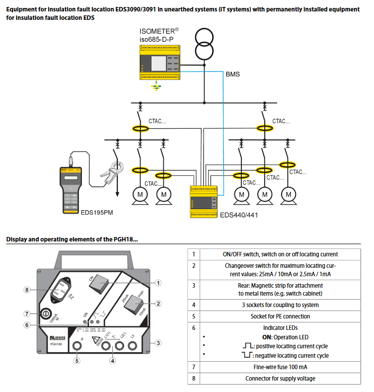
ISOMETER ® The iso685 series is an integrated insulation monitoring and fault location device developed by Bender, a German company. It is designed specifically for IT systems (ungrounded systems), with the core mission of real-time monitoring of insulation resistance, DC offset voltage, and other parameters. Combined with EDS (Insulation Fault Locator), it achieves accurate fault location and avoids the risk of electric shock and equipment damage. The product is divided into D-type (integrated display/button) and S-type (no display, requiring FP200 panel). The W-enhanced type has higher anti vibration and anti temperature performance (-40~+70 ℃), suitable for complex scenarios such as industrial automation and ship power, and complies with international standards such as IEC 61557-8.
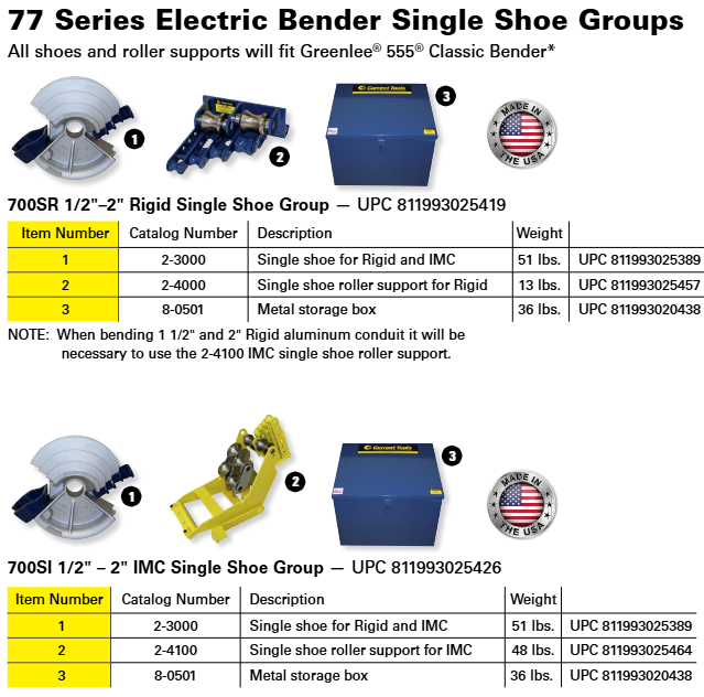
Core parameters and physical characteristics
Category specific parameters
Dimensions: Width 108mm, Height 93mm, Depth 110mm
Weight < 510g (excluding accessories)
Power supply requirements: AC/DC 24~240 V (tolerance -30%~+15%), frequency 50~400 Hz
Environmental adaptability standard type: working -25~+55 ℃, storage -40~+70 ℃; W-type: working -40~+70 ℃
Protection level terminal IP20, internal components IP40
Installation method: DIN rail installation (compliant with IEC 60715), screw installation (3 x M4 screws)
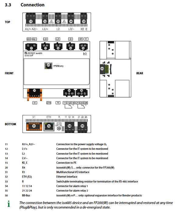
Adaptation system and measurement profile
(1) Scope of adaptation system
System type Voltage range Frequency range Maximum leakage capacitance
AC system 0~690 V (RMS) 0.1~460 Hz 0~1000 μ F (by profile)
DC system 0~1000 V -0~1000 μ F (according to profile)
3 (N) AC system 0~690 V (RMS) 50~60 Hz 0~150 μ F (power circuit profile)
(2) 6 measurement profiles
Profile type applicable scenario key parameters
Conventional constant frequency systems for power circuits measure a voltage of ± 50 V and a leakage capacitance of 0-150 μ F
Control circuits – Low voltage sensitive systems – Measurement voltage ± 10 V, voltage ≤ 230 V
Generator monitoring rapid measurement, frequency 50-60 Hz, leakage capacitance 0-5 μ F
Leakage capacitance of large capacitance systems such as ships with high capacitance ranging from 0 to 1000 μ F
Inverter>10 Hz (Inverter>10 Hz) 10~460 Hz Frequency conversion system leakage capacitance 0~20 μ F
Inverter<10 Hz (0.1~10 Hz) Low frequency system leakage capacitance 0~20 μ F
Detailed explanation of core functions
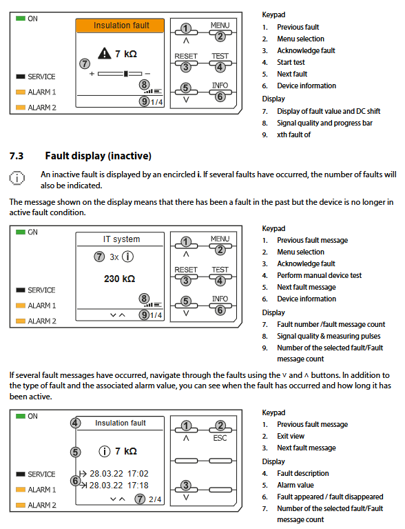
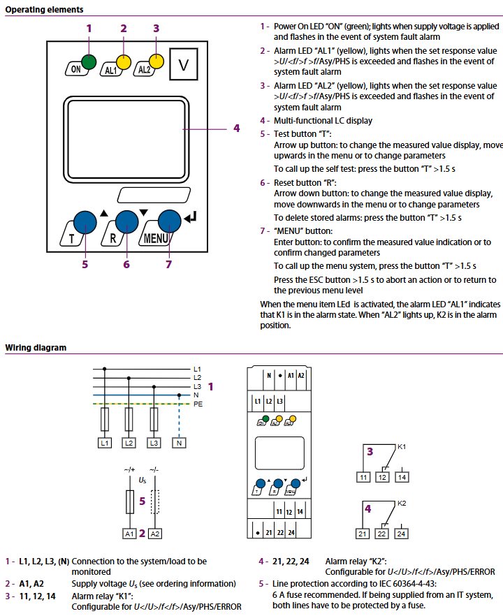
(1) Insulation monitoring function
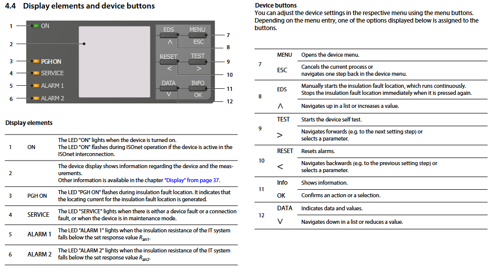
Dual alarm setting: The response values of ALARM1 (warning) and ALARM2 (main alarm) can be independently set between 1 k Ω and 10 M Ω, with default values of 40 k Ω and 10 k Ω, respectively. It supports 25% hysteresis to prevent false alarms.
Connection monitoring: Real time detection of L1/+, L2, L3/- line connections and PE grounding status, triggering sound and light alarms in case of abnormalities.
Data storage: The historical memory can store 1023 alarm/fault information, including date and timestamp, and cache for 3 days after power failure.
IsoGraph trend chart: supports visualization of insulation resistance changes by hour/day/week/month/year, with up to 100 measurement points.
(2) Insulation fault location (EDS function)
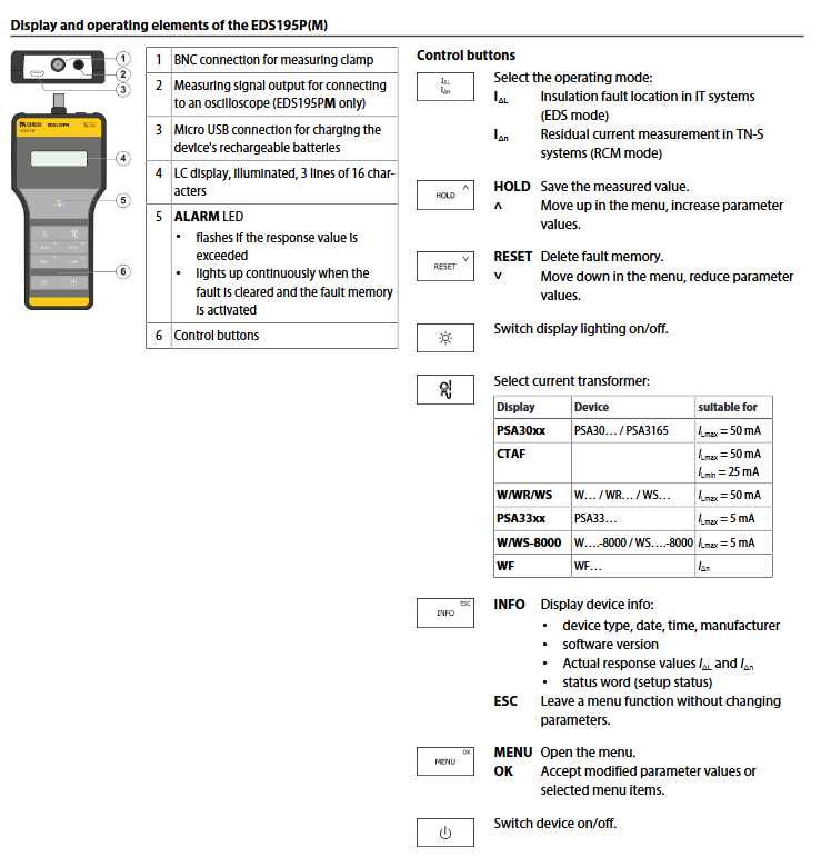
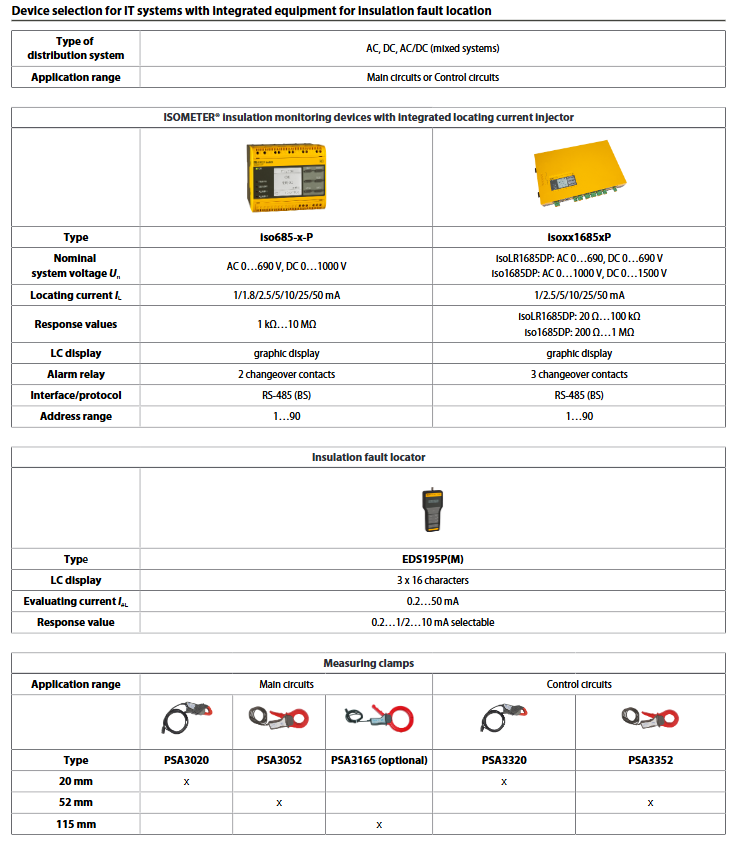
Compatible with EDS devices: Supports EDS440-S/L (positioning current 2~10 mA), EDS441-S/L (positioning current 0.2~1 mA), and can connect up to 21 EDSs (255 channels).
Positioning mode:
Manual mode: Continuous positioning, manual stop required;
Automatic mode: ALARM2 triggers and automatically starts, with a cyclic interruption for insulation measurement;
Cycle mode: ALARM2 triggers and starts one cycle before stopping.
Key parameters: The positioning current can be set to 1/1.8/2.5/5/10/25/50 mA, and the response value I Δ L (main alarm) is 200 μ A~10 mA.
(3) ISOnet system isolation
Function: Through Ethernet, multiple devices (≤ 20) can collaborate to ensure that only one device actively measures at a time, while the rest are isolated and in standby mode.
Configuration requirements: BCOM system name and subsystem address should be consistent, device address should be unique, and support automatic skipping of faulty devices.
Interface and Communication
Interface type communication protocol/functional key parameters
Ethernet (ETH) Modbus TCP, BCOM, Web Server 10/100 Mbit/s, up to 5 TCP connections
RS-485 (X1 interface) BS bus, Modbus RTU baud rate 9.6 kBd, transmission distance ≤ 1200 m
X1 multifunctional I/O digital input (3 channels), digital output (2 channels), analog output (1 channel), analog output supports 0~20 mA/0~10 V and other signals
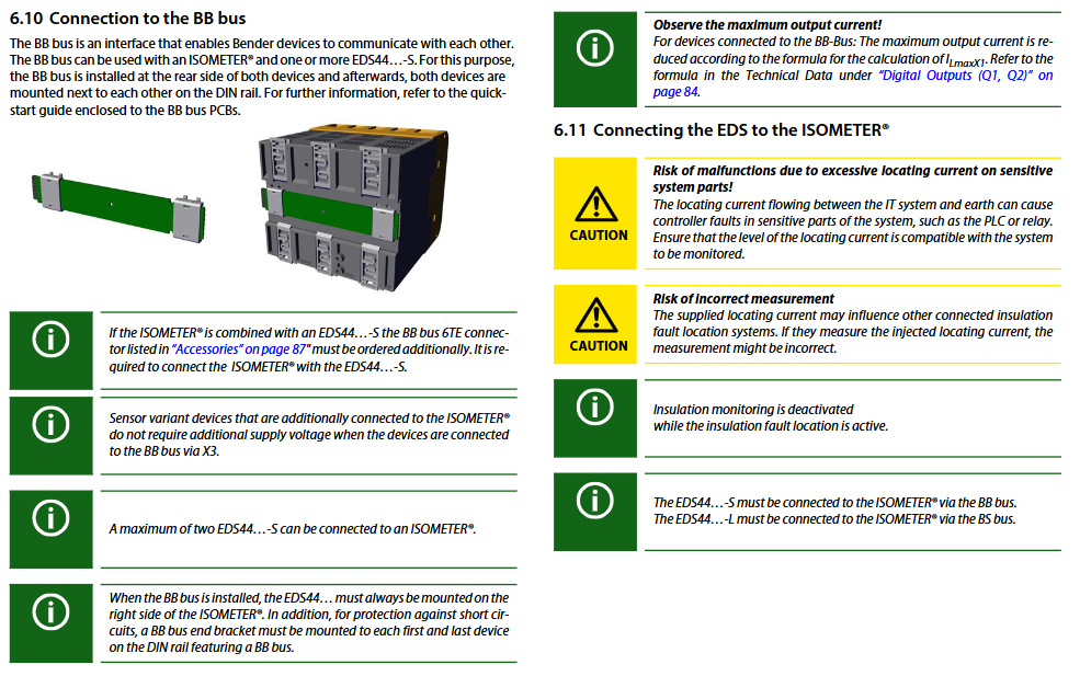
BB bus Bender internal device communication can connect up to 2 EDS44… – S devices without additional power supply
Web server remote parameter setting and data reading support Chrome/Firefox/Edge browsers, with write permission enabled
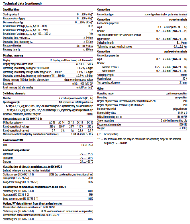
Operation and debugging process
(1) Basic debugging steps
Equipment installation: Choose the installation method, fix the equipment, and ensure the terminal spacing (horizontal 0mm, up and down 20mm);
Parameter configuration: Set language, date and time, system type, measurement profile, alarm response value, EDS mode, and positioning current through the debugging wizard;
EDS configuration: Scan EDS channel → Activate target channel → Set group parameters (CT type, response value, etc.);
Functional testing: Simulate insulation faults through grounding resistance to verify the accuracy of alarm triggering and fault location;
Operation monitoring: Check the standard display (insulation resistance+signal quality) and trace the data through isoGraph or historical memory.
(2) Alarm and fault handling
Alarm type triggering condition processing method
ALARM1 insulation resistance<Ran1 (default 40 k Ω) Observe the system status and troubleshoot if necessary
ALARM2 insulation resistance<Ran2 (default 10 k Ω), initiate EDS positioning, eliminate the fault, and reset
Check L1/+~L3/- wiring and PE connection for disconnection of faulty circuit or poor grounding of PE
EDS channel malfunction CT connection abnormality or channel not activated Rescan channel, check CT wiring
Maintenance and safety regulations
(1) Daily maintenance
No need for regular oil changes (sealed gearbox), if the cover is opened for maintenance, Mobil needs to be added ® 634 synthetic oil;
Regularly check the BS bus terminal resistance (120 Ω) to ensure stable communication;
Clean the display panel and terminals, ensure clear labeling and stickers, and replace worn parts in a timely manner.
(2) Safety regulations
Only professional personnel are allowed to install and debug. Before operation, the power must be turned off and the system must be confirmed to be out of power;
Power supply requires connection to a 24-240 V GFCI protection circuit, and modification of plugs/cables is prohibited;
When locating faults, avoid positioning current interference with sensitive components (such as PLC), and match the system tolerance value;
Only one device is allowed to actively measure in the coupled IT system, and the rest are isolated through ISOnet or digital input.
Ordering information and accessories
Product Model Description Product Number
Iso685-D-P with display/buttons, standard B91067030
Iso685W-D-P with display/buttons, W enhanced B91067030W
Iso685-S-P+FP200 without display+panel, standard type B91067230
EDS440-L-4 Insulation Fault Locator (2~10 mA) B91080202
EDS441-S-1 Insulation Fault Locator (0.2~1 mA) B91080204
Mechanical accessory terminal cover+installation clip B91067903