Call us 24/7uaedcs@163.com
Welcome to the official website of CNIACS Automation Technology Co., Ltd!
Call us 24/7uaedcs@163.com

Bently Nevada 3300 XL High Temperature Proximity

System core positioning and application scenarios

1. Core positioning

Addressing the pain point of traditional proximity probes being easily damaged in high-temperature environments, it can operate stably in continuous high temperatures up to+350 ° C (+662 ° F) and is used to measure key parameters such as vibration, thrust position, and differential expansion. It is compatible with Bently Nevada’s entire range of monitoring and diagnostic equipment.

Combining the dual value of “online monitoring and protection” and “research and development/troubleshooting”: it is used for real-time protection of key equipment in industrial sites, and also supports turbine mode shape analysis, helping new machine research and development and old machine fault diagnosis (such as shaft cracks, bearing failures, dynamic and static friction, etc.).

2. Typical application scenarios

Focusing on the high-temperature areas of gas turbines and steam turbines, including:

Near the labyrinth seal of the steam turbine, differential expansion measurement points;

Gas turbine bearing seat support pillar, probe for threading in exhaust path;

Monitoring of faulty bearings in high-temperature areas;

Modal analysis and online diagnosis of turbine mid span position;

Measurement of inter stage radial/axial sealing clearance at the mid span position of a multi-stage steam turbine to reduce sealing friction.

Core advantages and design features of the system

1. Extreme environmental adaptability

High temperature tolerance: The probe integrates a hard wired cable, with a rated continuous working temperature of+350 ° C (+662 ° F), far exceeding traditional probes;

Durable structure: Ceramic probe tip (sealed, moisture-proof, and anti pollution)+AISI 316L stainless steel shell (corrosion-resistant), can withstand 100% condensation humidity, and the probe connector can be submerged after protection;

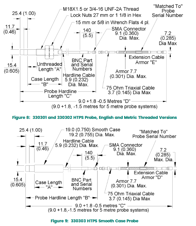
Flexible installation: Available in two styles: threaded housing (3/4-16 UNF, M18 × 1.5) and smooth housing. The smooth housing is paired with a clamping mounting bracket to solve the problem of difficult calibration in traditional threaded installation of long cable probes (2m/5m).

2. Performance and compatibility

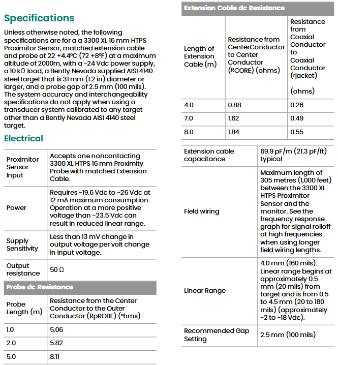
Measurement accuracy: Linear range of 4.0mm (160 mil, 0.5-4.5mm interval), incremental scaling factor (ISF) of 3.94 V/mm (100 mV/mil), best fit line deviation (DSL) of ≤± 78 μ m (± 3.1 mil), ISF deviation at high temperature (22-350 ° C) of ≤± 30%;

Fully compatible design: The signal output (3.94 V/mm) is compatible with all new and old Bently Nevada monitoring devices, supports field wiring up to 305 meters (1000 feet), and has a frequency response of 0-6kHz (± 0, -3dB).

Core technical specifications

1. Electrical specifications (default test conditions: 22 ± 4.4 ° C, 2000m altitude, -24Vdc power supply, AISI 4140 steel target)

Category key parameters

Power supply requirements input voltage -19.6~-26Vdc, maximum power consumption 12mA; voltage higher than -23.5Vdc will shorten the linear range

Output characteristics: Output resistance 50 Ω, power supply sensitivity ≤ 13mV/V (output change ≤ 13mV for every 1V change in input voltage)

Probe resistance 1m Probe: 5.06 Ω; 2m probe: 5.82 Ω; 5m probe: 8.11 Ω (center conductor outer conductor)

Extended cable capacitance 69.9pF/m; 4m cable resistance: core wire 0.88 Ω, coaxial conductor 0.26 Ω; 7m cable: core wire 1.62 Ω, coaxial conductor 0.49 Ω

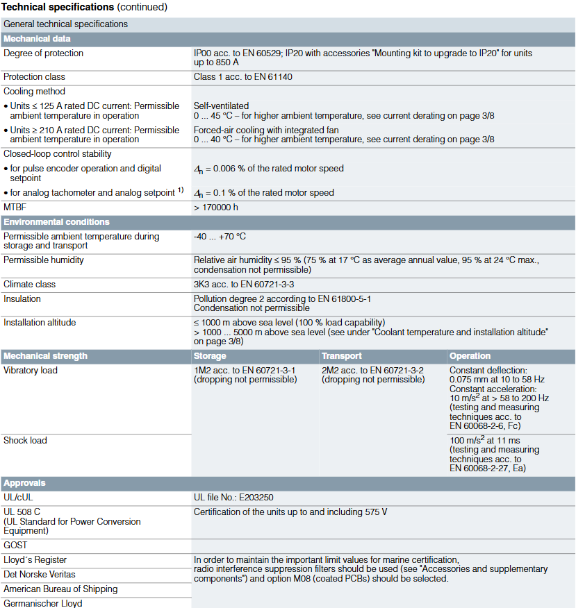
2. Mechanical and environmental specifications

Category key parameters

Material probe housing: AISI 316L stainless steel; Hardwire cable: AISI 304L stainless steel; Extension cable: FEP insulated 75 Ω triaxial cable; Sensor housing: epoxy powder coated aluminum

The total length of the size and weight system is 9m (including extension cables); Probe weight 117g/m (cable)+12g/cm (casing); Sensor weight 255g (9oz)

Maximum tensile strength of 289N (65 pounds, probe extension cable); The maximum torque of the probe housing is 81N · m (720 in. lb); Minimum bending radius 25.4mm (1in)

Temperature range probe: -34~+350 ° C (storage/operation); Extension cable: -52~+177 ° C; sensor: working -52~+100 ° C, storage -52~+105 ° C

Hardware composition and model classification

The system core consists of “probe+extension cable+Proximitor Sensor”, and each component model is subdivided by function, supporting customized selection:

1. Core probe model (Class 3)

Example of Key Parameters for Model Series Type Selection

330301 3/4-16 UNF threaded housing A (unthreaded length, 0.0-5.4in, 0.1in increments), B (total housing length, 1.1-6.5in, 0.1in increments), C (hard wire length: 10=1m/20=2m/50=5m), D (total length: 90=9m), E (armor: 00 none/01 present), F (certification: 00 not required) 330301-012-060-10-90-00-00 (unthreaded 1.2in, housing 6.0in, hard wire 1m, total length 9m, no armor, no certification)

330302 M18 × 1.5 threaded shell A (unthreaded length, 0-130mm, 10mm increments), B (total shell length, 30-160mm, 10mm increments), C/D/E/F are the same as 330301 330302-050-130-20-90-01-00 (unthreaded 50mm, shell 130mm, hard wire 2m, total length 9m, armored but not certified)

330303 Smooth Shell (with mounting bracket) A (total shell length, 0.6-9.9in, 0.1in increments), B (hard wire length), C (total length), D (armor), E (certified) 330303-060-10-90-00-00 (shell 6.0in, hard wire 1m, total length 9m, no armor, no certification)

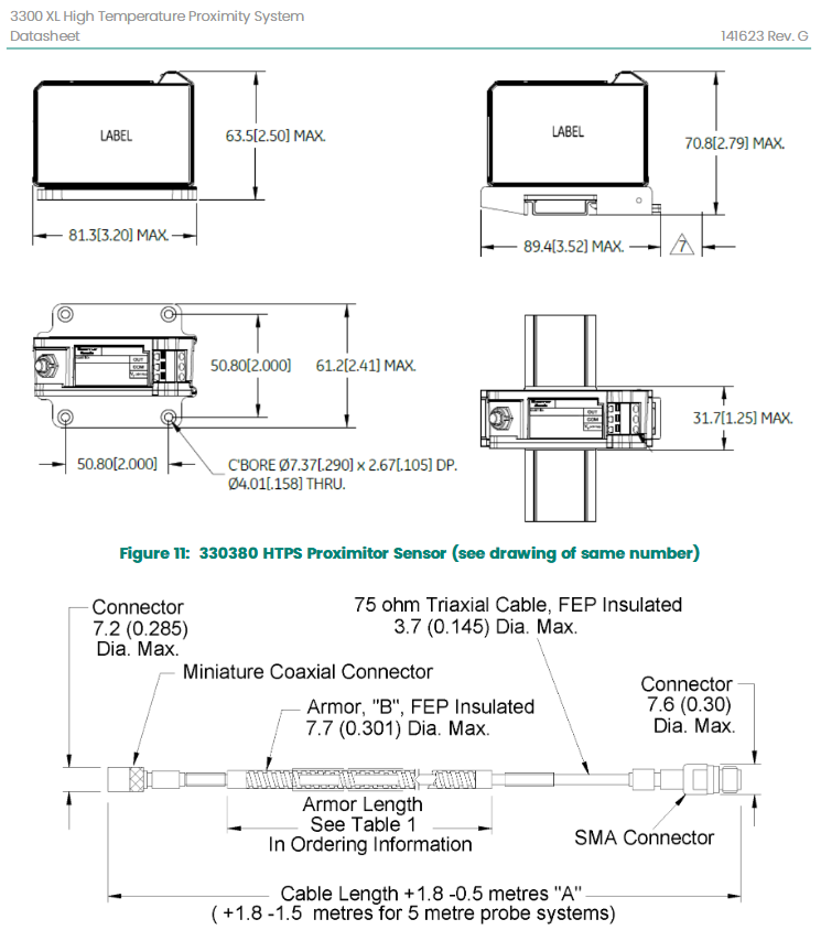
2. Sensor model (330380 series)

Replace the old model 330300, with a core distinction of “installation method” and parameters:

Selection parameter A (total length+installation): 90=9m panel installation, 91=9m DIN installation, 92=9m without installation hardware;

Selection parameter B (certification): 00=no certification required.

3. Accessories and extension cables

Backup extension cable (330330): It needs to match the original probe serial number, with a length of 4m (040)/7m (070)/8m (080), supporting armor (01 with/00 without);

On site wiring cable (132501): 18AWG (1.0mm ²) 3-core shielded wire, length 2-99 feet (0.6-30m), with wire lugs at both ends;

Documents and Bracket: 125M6030 (User Guide), 159132 (Performance Specifications), 134835-01 (330303 Probe Backup Installation Bracket).

​Compliance and Precautions

1. Compliance certification

Electromagnetic compatibility: compliant with EU CE certification;

Environmental Protection: Compliant with RoHS Directive 2011/65/EU;

Wireless interference: Complies with FCC Part 15 regulations (does not generate harmful interference, and is tolerant of interference).

2. Key precautions

Target material requirements: System accuracy based on Bently Nevada AISI 4140 steel target (diameter ≥ 31mm), using other target materials may affect accuracy;

Small shaft diameter measurement: When the shaft diameter is less than 76mm (3in), attention should be paid to the electromagnetic interference of the probe (radial vibration probe spacing ≥ 54mm, axial position ≥ 64mm). When the shaft diameter is less than 152mm (6in), it will cause changes in the proportional coefficient, and reference should be made to specification 159132;

Pressure and Leakage: The probe is designed to seal the pressure difference between the tip and the housing, but pressure testing is not conducted at the factory; High/low pH solutions may corrode the probe tip and cause leakage. Bently Nevada is not responsible for any leakage damage, and the leaking probe is not covered by the service plan warranty.

Siemens SINAMICS DCM DC Converter and Control Module

Core components of the product

The SINAMICS DC MASTER series DC converter consists of multiple key functional modules, which work together to achieve DC drive control. The specific components and functions are as follows:

Electronic module: Integrated control unit (CUD) with reserved rotatable bracket slots, supporting additional CUD expansion to enhance control flexibility and redundancy.

Power section: A fully controlled three-phase bridge circuit is constructed using thyristors, which are divided into two driving types – two quadrant driving (B6C structure) and four quadrant driving ((B6) A (B6) C structure), to meet the speed and braking requirements under different operating conditions.

Cooling system: Equipment with a rated DC current ≤ 125A adopts a self ventilated design, while equipment with a rated DC current ≥ 210A is equipped with an integrated fan for forced air cooling to ensure stable operation of power components.

Excitation power section: Standard single quadrant excitation power unit (including freewheeling circuit), optional non excitation version or two quadrant excitation version (suitable for high dynamic excitation current change scenarios), and integrated excitation overvoltage protection function.

Power supply and operation unit: including electronic device power supply; Standard BOP20 operation panel, AOP30 advanced operation panel requires additional purchase.

General Technical Specifications

1. Standard compliance

The product complies with multiple international and industry standards to ensure electrical safety, electromagnetic compatibility, and operational reliability. The core standards are listed in the table below:

Standard Number, Standard Name, and Scope of Application

EN 50178/IEC 62103 Electronic Equipment Standard for Power Facilities

EN 50274 Low voltage switchgear and control equipment components: Protection against electric shock (preventing accidental direct contact with hazardous live parts)

EN 60146-1-1 Semiconductor converters: General requirements and specifications for grid commutated converters

EN 61800-1 Adjustable Speed Electric Drive Systems Part 1: (DC Drive) General Requirements and Rating Specification for Low Voltage Adjustable Speed DC Drive Systems

EN 61800-3 Adjustable Speed Electric Drive Systems Part 3: Electromagnetic Compatibility (EMC) Product Standard with Specific Test Methods

EN 61800-5-1 Adjustable Speed Electric Drive Systems Part 5-1: Safety Requirements (Electrical, Thermal, and Energy Related)

UL 508 C Power Conversion Equipment UL Standard (575V and below equipment certified, UL file number E203250)

2. Electrical safety and performance

Overvoltage level and strength: The overvoltage level of the power supply circuit is EN 61800-5-1 Class II, which is Class III relative to the environment (other power supply circuits, enclosures, electronic devices); The overvoltage strength meets the EN 50178 Class 1 standard.

Short circuit current: Different combinations of supply voltage and rated DC current correspond to different maximum short-circuit currents. For example, in a 400/480V three-phase AC power supply, the maximum short-circuit current for equipment with a rated DC current of 15-1200A is 65kA, and for equipment with a rated DC current of 3000A, it can reach 100kA.

Radio interference suppression: The radio interference suppression function that complies with the EN 61800-3 standard is not configured. Additional accessories need to be purchased to meet the relevant requirements.

3. Stability of closed-loop control

Based on the thermal operation status of the equipment (rated motor speed), under specific premise conditions (ambient temperature ± 10 ℃, supply voltage ± 10%/-5%, temperature coefficient of the speed measuring generator with temperature compensation 0.15 ‰/10 ℃, constant given value), the control accuracy is as follows:

Pulse encoder operation+digital setpoint: speed deviation ∆ n=0.1% rated motor speed

Simulated speedometer+simulated setpoint: speed deviation ∆ n=0.006% rated motor speed

4. Environmental and mechanical parameters

Specific requirements for parameter categories

Basic protection level IP00 (EN 60529); Devices with ≤ 850A can be upgraded to IP20 through the “IP20 Upgrade Installation Kit”; Electrical safety level EN 61140 Class 1

Temperature range operation: ≤ 125A equipment 0-45 ℃, ≥ 210A equipment 0-40 ℃ (high temperature requires capacity reduction); Storage/transportation: -40-70 ℃

Relative humidity ≤ 95% (at 24 ℃), annual average ≤ 75% (at 17 ℃), condensation is strictly prohibited

Climate grade EN 60721-3-3 3K3

Insulation pollution level EN 61800-5-1 Class 2, condensation is strictly prohibited

Installation height ≤ 1000m altitude (100% load capacity); 1000-5000m altitude needs to refer to the derating specifications

Mechanical strength vibration: storage of 1M2 (EN 60721-3-1), transportation of 2M2 (EN 60721-3-2), constant deflection of 0.075mm during operation at 10-58Hz/constant acceleration of 10m/s ² during 58-200Hz; Impact: 100m/s ² (11ms, EN 60068-2-27 Ea) during operation

Mean Time Between Failures (MTBF)>170000 hours

5. Certification qualifications

In addition to UL/cUL certification, the product also complies with GOST standards and has been certified by Lloyd’s Register, Det Norske Veritas, American Bureau of Shipping, and Germanischer Lloyd (ship certification requires radio interference suppression filters and M08 option – coated PCB).

Typical model technical parameters (taking 480V three-phase AC and four quadrant operation as an example)

For the series models with rated armature supply voltage of 480V three-phase AC (± 10%/-20%) and four quadrant operation, the core parameters are shown in the following table (some key models):

Model Rated armature input current (A) Rated DC voltage (V) Rated DC current (A) Rated power (kW) Rated excitation voltage (V) Rated excitation current (A) Cooling air demand (m ³/h) Sound pressure level (dB (A)) Size (W × H × D, mm) Weight (kg)

6RA8078-6FV62-0AA0 232 500 280 140 480 two-phase AC 15 300 52.4 268 × 385 × 252 15

6RA8082-6FV62-0AA0 374 500 450 225 480 two-phase AC 25-268 × 625 × 275 31

6RA8085-6FV62-0AA0 498 500 600 300 480 two-phase AC 25 600-268 × 700 × 311 42

6RA8087-6FV62-0AA0 706 500 850 425 480 two-phase AC 30 1000 64.5 268 × 785 × 435 78

6RA8091-6FV62-0AA0 996 500 1200 600 480 two-phase AC 40-268 × 785 × 435-

Note: The armature/excitation supply voltage can be set to be lower than the rated value through parameter settings. The minimum input voltage for 400/480/575V rated voltage equipment is 50V, and for higher rated voltage equipment it is 85V. When the supply voltage undervoltage is ≤ 5%, the rated DC output voltage can be maintained.

Selection and ordering data

1. Core dimensions for selection

Selection should be based on armature circuit parameters (supply voltage, rated DC voltage/current), excitation circuit parameters (supply voltage, rated DC current), rated power, matched with corresponding models and matching fuses. Different supply voltages (400V/480V/575V/690V/830V/950V three-phase AC) correspond to different model sequences, for example:

400V three-phase AC: 6RA80xx-6DV62-0AA0 series

480V three-phase AC: 6RA80xx-6FV62-0AA0 series

575/690V three-phase AC: 6RA80xx-6GV62-0AA0 series

2. Rules for matching fuses

Different models require specific types and specifications of armature/excitation circuit fuses, such as:

6RA8013-6FV62-0AA0 (480V three-phase AC, 15A rated DC current): armature fuse 3NE1814-0 (2 pieces), excitation fuse 5SD420

6RA8087-6FV62-0AA0 (480V three-phase AC, 850A rated DC current): armature fuse 3NE3338-8+3NE3334-0B (parallel), excitation fuse 5SD480

High current models (such as 6RA8091-6FV62-0AA01200A rated DC current): Built in armature fuse, no external semiconductor fuse required, excitation fuse 3NE1802-0 (UL certified)

Schneider Electric 31H7 series

Core functions and application positioning

1. Core protection and control functions

Multiple fault protection: As a low-voltage distribution protection component, the core function of the 31H7 series is to monitor the current of the distribution circuit, trigger protection actions for faults such as overload (continuous current exceeding the set value), short circuit (instantaneous surge of current), etc. (such as cutting off the circuit, disconnecting the load), avoid overheating of the circuit, equipment burnout, and reduce the risk of electrical fires.

Overload protection: with adjustable action threshold and delay characteristics, suitable for different power distribution circuits (such as lighting circuits, small motor circuits), can avoid triggering protection by starting surge current.

Short circuit protection: adopting instantaneous action design (millisecond level response), quickly cutting off the fault circuit, limiting the impact of short-circuit current on the distribution system, and protecting upstream circuit breakers and distribution equipment.

Circuit control assistance: Some models may integrate manual opening and closing functions, support on-site start stop control of the distribution circuit, and have status indicators (such as LED lights displaying circuit on/off/fault status), making it easy for operation and maintenance personnel to quickly identify the circuit status.

2. Typical application scenarios

Based on the document association of “PSS (Power System Solutions)” and “NWEQUIP” identification, the 31H7 series is mainly suitable for the following scenarios:

Commercial building power distribution: such as lighting circuits in office buildings and shopping malls, and power distribution protection for air conditioning terminal equipment (fans, coils);

Industrial auxiliary power distribution: protection of auxiliary circuits in factory workshops (such as control power supply and small instrument power supply circuits);

Special adaptation for North American market: If “NWEQUIP” refers to the North American market, the product must comply with North American low-voltage electrical standards (such as UL 489), adapt to 120V/240V commonly used low-voltage distribution systems in North America, and can be used for commercial or industrial projects in North America.

Key technical specifications (derived from the commonalities and scenarios of the “31Hx” series)

1. Electrical parameters

Speculative Category/Common Parameters

Rated voltage (U ₙ) – North American market adaptation: AC 120/240V single-phase, or AC 208/480V three-phase (compliant with North American low voltage distribution standards);

-General industrial scenario: AC 220/380V three-phase (if covering the global market)

The rated current (I ₙ) is based on the common specifications of the “31H7” series, and it is estimated that the rated current range is 1A-30A (suitable for small and medium power distribution circuits, such as lighting and small motors). Specific models need to be distinguished by suffixes (for example, the suffix “10” of a certain model represents 10A)

Protection action characteristics – Overload protection: Complies with IEC 60947-2 or UL 489 standard “Class 10” (overload action delay of 10 seconds @ 1.5 times rated current), suitable for most distribution loads;

-Short circuit breaking capacity: ≥ 10kA at AC 240V (meeting the short-circuit current requirements of commercial and light industry)

Common pole numbers include 1 pole, 2 poles, or 3 poles: 1 pole is suitable for single-phase lighting circuits, 2 poles are suitable for single-phase power circuits (such as air conditioning), and 3 poles are suitable for three-phase small motor circuits

2. Environment and physical characteristics

Work environment:

Working temperature range: -30 ℃ to+60 ℃ (industrial grade wide temperature design, suitable for indoor and outdoor distribution cabinet environment);

Humidity range: 0-95% (non condensing), suitable for humid environments such as underground garage power distribution and auxiliary circuits in food processing workshops.

Protection level:

It is speculated to be IP20 (touch resistant, dust-proof), suitable for installation inside distribution cabinets (non outdoor or dust direct contact scenarios); Some models may provide IP40 protection (enhanced dust prevention) for industrial auxiliary areas with high levels of dust.

Installation and wiring:

Installation method: Supports DIN rail installation (compliant with EN 50022 or North American NEMA standard rails), making it easy to integrate with other Schneider low-voltage components such as contactors and surge protectors;

Wiring method: Screw terminal wiring, suitable for wire cross-sectional area of 0.5-4mm ² (meets current carrying requirements of 1A-30A, compatible with multiple specifications of wires).

Product identification and compliance

1. Model coding logic (based on Schneider low-voltage component rules)

Taking the relevant models of “31H7NWEQUIP” as an example, the meanings of each part of the code are speculated as follows:

31H7 “: Core series code, representing Schneider’s specific low-voltage distribution protection component series;

NW “: Regional/characteristic identifier, corresponding to” NWEQUIP “, speculated to be” North America “or” New “, indicating market adaptation or product generation;

Suffix (such as current specification): The complete model identification should include the rated current suffix (such as “31H7-10” representing 10A rated current), please refer to the official model table for details.

2. Certification and Compliance

As a standardized product of Schneider, the 31H7 series must comply with the electrical safety standards of the target market:

North American market: UL 489 (Low Voltage Circuit Breaker Standard), CSA C22.2 No.5 (Canadian Low Voltage Electrical Standard);

Global market: IEC 60947-2 (International Low Voltage Switchgear Standard), CE certification (EU access);

Chinese market (if imported): CCC certification (China Compulsory Certification).

ABB System 800xA wired network switch

This document is a technical data sheet for ABB System 800xA series wired network switches, covering 5 core switch models (NE801, NE802, NE810, NE820, NE840) and supporting SFP optical modules, designed specifically for industrial distributed control systems (DCS), providing stable and redundant network communication support, suitable for harsh industrial scenarios such as power, chemical, metallurgical, etc. The core advantages include pre configured adaptation, enhanced monitoring, long life, and comprehensive technical support.

Series General Core Features

System 800xA deep adaptation: factory pre configured, can be directly connected to ABB System 800xA DCS system, without complex debugging, reducing integration difficulty.

Enhanced Network Monitoring: Supports real-time monitoring of network status, fault diagnosis, and traffic management through PNSM (Plant Network and Security Manager) tools, improving operational efficiency.

Industrial grade reliability:

Wide temperature working range (minimum -40 ℃, maximum 74 ℃), suitable for high and low temperature industrial sites;

Some models have an IP40 protection level (dustproof), while NE801/802 has an IP21 protection level (splash proof), meeting the requirements of different installation environments;

Support redundant power input (except for NE840, which is designed with dual power supply) to avoid network interruption caused by single point power failure;

Compliant with G3 compliance and multiple industrial EMC and safety standards (such as EN 50121-4, UL/IEC/EN 60950-1), with strong resistance to electromagnetic interference.

Long lifespan and service guarantee: The average time between failures (MTBF) can reach up to 1.18 million hours (NE802), and the equipment has strong stability; ABB provides full lifecycle technical support to reduce maintenance risks in the later stages.

image.png

Comparison of Technical Parameters of 5 Core Switch Models

1. Basic information and physical characteristics

Model, Order Number, Management Type, Size (W × H × D), Weight, Protection Level, Installation Method

NE801 3BSE080209R1 Lightweight Management (DIP Switch) 34 × 123 × 121 mm 0.2 kg IP21 DIN Rail

NE802 3BSE080237R1 Lightweight Management (DIP Switch) 34 × 123 × 121 mm 0.2 kg IP21 DIN Rail

NE810 3BSE080207R1 Fully Managed 52 × 100 × 101 mm 0.7 kg IP40 DIN Rail

NE820 3BSE080208R1 Fully Managed Type 175 × 105 × 122 mm 2.2 kg IP40 DIN Rail

NE840 3BSE080211R1 Fully Managed 466 × 258 × 43 mm 3.8 kg IP40 Rack Mounted (19 inches)

2. Electrical and network characteristics

Model: Operating Voltage, Rated Current (Typical Value), Ethernet Electrical Port (TX), Ethernet Optical Port (SFP), Digital I/O Console Interface

NE801 9.6-57.6 VDC (redundant) 350 mA @ 12 VDC 4 × 10/100 Mbit/s 1 × 100 Mbit/s (LC interface) 1 × 4 ports Removable terminals 1 × 2.5 mm jack

NE802 9.6-57.6 VDC (redundant) 100 mA @ 12 VDC 4 × 10/100/1000 Mbit/s 1 × 100/1000 Mbit/s (LC interface) 1 × 4 ports Removable terminals 1 × USB Micro-B

NE810 19-60 VDC (redundant) 240 mA @ 24 VDC 8 × 10/100 Mbit/s 4 × 100/1000 Mbit/s 1 × 4 ports Removable terminals 1 × USB Micro-B

NE820 16-60 VDC (redundant) 120 mA @ 48 VDC 8 × 10/100 Mbit/s+7 × 10/100/1000 Mbit/s 4 × 100/1000 Mbit/s -1 × USB Micro-B

NE840 90-264 VAC(47-63 Hz) 350 mA @ 120 VAC(60Hz); 220 mA @ 240 VAC(50Hz) 8×10/100 Mbit/s + 7×10/100/1000 Mbit/s 4×100/1000 Mbit/s – 1×USB Micro-B

3. Environment and reliability

Model Operating Temperature Storage/Transportation Temperature MTBF (hours, MIL-HDBK-217K standard)

NE801-25 to+70 ℃ -25 to+70 ℃ 500000

NE802-40 to+74 ℃ -40 to+85 ℃ 1182374

NE810-40 to+70 ℃ -50 to+85 ℃ 630000

NE820-40 to+70 ℃ -50 to+85 ℃ 303000

NE840-40 to+55 ℃ -40 to+85 ℃ 123000

Supporting SFP optical module (transceiver) specifications

ABB offers 20 different types of SFP optical modules (PT801-PT839), covering 100Mbps and 1000Mbit/s rates, supporting multimode, single-mode, and bidirectional (BiDi) fiber transmission, and adapting to different distances and fiber type requirements. The core parameters are as follows:

General characteristics:

Interface type: LC (optical module), RJ45 (electrical module);

Working temperature: -40 to+85 ℃, industrial grade wide temperature design;

Supported wavelengths: 850 nm (multimode), 1310 nm, 1490 nm, 1550 nm (single-mode).

Core model classification (by speed):

100Mbps optical module:

Multimode (PT801): transmission distance of 2 km, wavelength of 1310/1310 nm;

Single mode (PT802/805/808/811): up to 120 km (PT8111550/1550 nm);

Bidirectional single-mode (PT803/804/806/807/809/810/812/813): transmitted through a single core fiber, with a maximum distance of 120 km.

Gigabit optical module (1000 Mbit/s):

Multimode (PT831/832): up to 2 km (PT8321310/1310 nm);

Single mode (PT833/836/837/838): up to 110 km (PT8381550/1550 nm);

Bidirectional single-mode (PT834/835): transmission distance of 20 km, wavelength of 1310/1490 nm.

Gigabit electric module (PT839): RJ45 interface, transmission distance of 100 meters, suitable for short distance copper cable connection.

Certification and Compliance

All switches and optical modules comply with multiple international standards to ensure safety and compatibility:

EMC (Electromagnetic Compatibility): EN 50121-4 (Railway Signal Equipment), EN 55022/EN 55024 (IT Equipment), EN 61000-6-1/2/3/4 (Environmental Immunity and Emissions) FCC Part 15 Class A;

Security certification: UL/IEC/EN 60950-1 (IT equipment security), DNV 2.4 (marine certification);

Environmental compliance: EN 50581:2012 (RoHS), Directive/2012/19/EU (WEEE).

image.png

Woodward ESDR 4/4T current differential protection relay

ESDR 4/4T is a series of current differential protection relays launched by Woodward, specifically designed for three-phase current differential protection of generators, motors, and interconnecting transformers. By accurately monitoring the current on both sides of the protection area, identifying fault types, and triggering selective tripping, it ensures the safe and stable operation of power equipment. It is divided into two versions: ESDR 4 (for generators/motors) and ESDR 4T (for generators/motors/interconnecting transformers), and is suitable for harsh power consumption scenarios in industrial, energy, and other fields.

Core Features and Version Differences

1. General core functions

High precision current monitoring: supports 6-channel True RMS current measurement, covering three-phase systems on both sides of the protection area, and can be adapted to the secondary output of current transformers (../1A or…) ./5 A)。

Flexible fault protection: configurable trip thresholds and delays for differential current (Id) and stable current (Is), accurately identifying two-phase/three-phase short circuits and grounding faults; Only when a fault occurs within the protected area, will it trigger a trip, and external faults will not act, achieving selective protection.

Multi interface and alarm: equipped with 4 alarm relays (air contact output) and 3 discrete inputs (for locking, confirmation, and configuration), supporting external PLC remote control; The dual row LC display screen displays real-time operating status and parameters, and supports front-end panel configuration operations.

Reliable hardware design: using microprocessor technology to ensure measurement accuracy, repeatability, and reliability; Compliant with CE certification, UL/cUL certification (for general locations), ESDR 4T additionally has German Lloyd’s (GL) certification, suitable for complex industrial electromagnetic environments.

2. Version difference (ESDR 4 vs ESDR 4T)

Functional dimension ESDR 4 (generator/motor specific) ESDR 4T (including interconnection transformer protection)

The protected objects are only generators, electric motors, generators, electric motors, and interconnecting transformers

Transformer adaptation function is not available. 1. Configurable transformer ratio (independent setting on high and low voltage sides)

2. Transformer vector groups (such as Yd5, Yy0, and 12 other types) can be selected

3. Equipped with transformer excitation inrush current detection and suppression function

Certification standards CE, UL/cUL CE, UL/cUL, GL (German Lloyd’s)

The core advantage is lightweight protection for simple loads, taking into account the complex working conditions of transformers, and adapting to multiple types of power system topologies

Key technical specifications

1. Electrical parameters

Category specification details

Power supply and power consumption: 24 Vdc (± 25% fluctuation); Inherent power consumption: maximum 6 W

Current measurement – isolation design, rated current (I ₙₐₜₑₙ): ./1A or ./5 A

-Current carrying capacity: 5.0 × I ₙₐₜₑₙ; Load:<0.15 VA

-1-second rated short-time current: The./1A version is 100.0 × I ₙₐₜₑₙ, and the./5A version is 30.0 × I ₙₐₜₑₙ

Discrete input isolation design; Input range: 18-250 Vac/dc; Input resistance: approximately 68 k Ω

Relay output – air contact (AgCdO contact material)

-Universal Load (GP): 24 Vdc@2  Adc、250  Vac@2  Aac

-Indicating load (PD): 24 Vdc@1  Adc

2. Environmental and physical parameters

Category specification details

Environmental adaptability – Operating temperature: -20 to 70 ° C (-4 to 158 ° F)

-Storage temperature: -40 to 85 ° C (-40 to 185 ° F)

-Working humidity: 95% (non condensing)

Mechanical Structure – Shell Standard: APRANORM DIN 43700; Protection level: Front IP42, Back IP21

-Size: 144 × 72 × 199 mm (width × height × depth); Front opening: 138 [+1.0] × 68 [+0.7] mm

-Installation method: Front panel installation or DIN rail installation (optional rail clamp P/N LR05188 required)

-Terminal block: screw/plug type, supporting 2.5 mm ² (14AWG) or 4 mm ² (12AWG) wires

-Weight: Approximately 1000 grams

Anti interference and certification – Anti interference testing: compliant with relevant EN standards (CE certification requirements)

-Certification: UL/cUL (ordinary premises), ESDR 4T with additional GL certification included

3. Transformer vector group (ESDR 4T exclusive)

Supports 12 common transformer vector group configurations, adapting to different wiring methods by adjusting phase offset. Some core vector groups are as follows:

Vector group wiring method and phase shift

Yd5 high voltage side Y connection, low voltage side Δ connection, offset 5 × 30 °=150 °

Yy0 high voltage side Y connection, low voltage side Y connection, offset by 0 °

Dy11 high voltage side Δ connection, low voltage side Y connection, offset 11 × 30 °=330 °

Dd6 high voltage side Δ connection, low voltage side Δ connection, offset 6 × 30 °=180 °

Ordering Information and Installation

1. Product model (P/N)

Different installation methods and current specifications correspond to different models, and the core models are as follows:

Product Version Installation Method Current Specification Product Number (P/N)

ESDR 4 Front Panel Installation…/1 A LR20459 (ESDR401B)

Front panel installation…/5 A 8441-1010 (ESDR405B)

DIN rail installation…/1 A 8441-1105 (ESDR401M)

DIN rail installation…/5 A LR20590 (ESDR405M)

ESDR 4T Front Panel Installation…/1 A LR20021 (ESDR4T01B)

Front panel installation…/5 A 5448-897 (ESDR4T05B)

DIN rail installation…/1 A LR20616 (ESDR4T01M)

DIN rail installation…/5 A 8441-1047 (ESDR4T05M)

Optional accessories: Front panel version converted to DIN rail mounting rail clamp, P/N LR05188.

2. Installation and wiring

Installation requirements: Must comply with DIN 43700 standard hole size to ensure protection level (front IP42 should avoid direct liquid spray); DIN rail installation requires the use of specialized rail clamps to ensure stable fixation.

Wiring precautions: The current input should be distinguished on both sides of the protection area (such as the high and low voltage sides of the transformer), and the discrete input and relay output should be connected according to the Wiring Diagram to avoid polarity errors that may cause protection misoperation.

Meggitt Modular CPU card and input / output card

CPUM and IOCN are Vibro Meter under Meggitt Sensing Systems ®  The core components of the VM600 series mechanical protection system (MPS) and condition monitoring system, which work together to achieve configuration management, signal monitoring, alarm control, and external device communication for VM600 racks, are suitable for harsh industrial scenarios such as aviation, energy, and heavy machinery.

Core functions and features

1. System configuration and control (CPUM core role)

One click configuration: VM600 MPSx software can be run on an external computer (laptop, industrial PC), and all VM600 cards can be configured with one click via Ethernet or RS-232 serial port.

Rack Control Center: As the “rack controller”, it establishes an Ethernet connection between the VM600 rack and the computer running MPSx software (MPS1/MPS2), and manages all cards in the rack uniformly.

Local monitoring and operation: The front panel is equipped with an LCD micro display screen, which displays the selected monitoring output values in the form of bar charts and numbers, while marking the Alert and Danger thresholds; Support switching monitoring signals through SLOT and OUT buttons, and reset the full rack lock alarm and associated relays with ALARM RESET button.

2. Multi interface communication and redundancy design

Rich communication interfaces: CPUM comes standard with 2 Ethernet interfaces and 2 serial ports (RS-232/RS-422/RS-485), and can be optionally equipped with a serial communication module to expand with an additional 2 isolated RS-422/RS-485 interfaces, supporting up to 3 serial ports working simultaneously.

Redundancy guarantee: configurable redundant communication links (Ethernet redundancy, serial port redundancy) to enhance system availability; For example, dual Ethernet is used for primary/backup Modbus TCP communication, and dual serial ports are used for primary/backup Modbus RTU communication.

Third party device compatibility: Supports industrial standard protocols (Modbus RTU, Modbus TCP), and can achieve data exchange with third-party devices such as DCS (Distributed Control System) and PLC (Programmable Logic Controller).

3. Security protection mechanism

Rack security level: Integrated two-level security protection functions – “hardware level” CPUM access locking, “software level” MPS password verification, restrict Ethernet connections from operating MPS functions, and avoid interfering with device monitoring and protection operations.

Status diagnosis: The DIAG (diagnostic) LED light on the front panel provides real-time feedback on the operating status. A constant green light indicates normal operation; Flashing green indicates normal operation but subject to rack safety restrictions; Extinguishing indicates abnormality.

4. The interface extension function of IOCN

Communication interface transfer: As a supporting IO card for CPUM, it provides standardized interfaces (RJ45, RJ11/RJ25, D-sub) to transfer CPUM’s main/backup Ethernet and serial signals to the outside, such as transferring CPUM’s main Ethernet from the “NET” interface to IOCN’s “1” interface.

Extended serial port support: When the CPUM is equipped with an optional serial communication module, IOCN’s “A” and “B” interfaces can provide an additional 2 RS-422/RS-485 interfaces, supporting multi node RS-485 network configuration for VM600 racks.

Key technical specifications

1. CPUM core parameters

Category specification details

CPU module model: PFM-541I or equivalent; Processor: AMD Geode ™  LX800(500MHz); Memory: 256MB DRAM; Operating System: QNX

Power supply and power consumption Power supply voltage: 5VDC ± 5%; Power consumption:<10W; CPU module powered separately:+5VDC (<1.8A)

Communication Interface – Main Ethernet: 10/100BASE-TX (100Mbps), RJ45 interface, used for MPSx configuration and Modbus TCP

-Backup Ethernet (requires IOCN): 10/100BASE-TX, RJ45 interface (IOCN’s “2” interface), used for redundant Modbus TCP

-Main serial port: RS-232 (115.2kBaud), 9-pin D-sub interface, used for MPSx direct connection configuration

-Backup serial port (IOCN required): RS-232/RS-485 (115.2kBaud), RJ11/RJ25 interface (IOCN’s “RS” interface), used for Modbus RTU

-Extended serial port (optional module required): 2-channel isolated RS-422/RS-485, RJ11/RJ25 interface (IOCN’s “A” and “B”)

Environmental adaptability working temperature: -20 to+65 ℃ (-4 to+149 ℉); Storage temperature: -25 to+80 ℃ (-13 to+176 ℉); Humidity: 0-90% (non condensing)

Physical dimension height: 6U (262mm); Width: 40mm; Depth: 187mm; Weight: Approximately 0.40kg (0.88lb)

2. IOCN core parameters

Category specification details

Interface type – Ethernet: 2 RJ45 (“1” for primary Ethernet adapter, “2” for backup Ethernet)

-Serial port: 1 RJ11/RJ25 (“RS”, backup serial port), 2 pairs of RJ11/RJ25 (“A” “B”, extended serial ports)

Isolation performance RS-485 isolation: 500VDC; Extended serial port module isolation:>100VDC

Power supply and power consumption Power supply voltage: 5VDC ± 5%; Power consumption:<2W

Physical dimension height: 6U (262mm); Width: 20mm; Depth: 125mm; Weight: Approximately 0.25kg (0.55lb)

3. LED and button functions

LED indicator lights: DIAG (diagnostic), OK (current channel normal), A (current channel warning, yellow), D (current channel dangerous, red).

Buttons: ALARM RESET (Reset Full Rack Alarm), SLOT ± (Switch Rack Slot), OUT ± (Switch Current Slot Channel).

Version differences and ordering information

1. Product version classification

Product Version Type Core Features Order Number (Example)

CPUM Ethernet Redundancy Edition comes standard with CPU module, 2 Ethernet+2 serial ports, including front-end display screen and OS authorization 601-003-000-VVV \ 3 \ 610-1CC-CCC (equivalent to 200-595-OSs-33h)

The Ethernet redundancy painted version is the same as the Ethernet redundancy version, with the addition of a conforming coating to enhance environmental protection 601-003-000-VVV \ 3V \ 610-1CC-CCC (equivalent to 200-595-0Ss-33hl)

The serial redundancy version includes a CPU module and a serial communication module, supporting 2 Ethernet ports and 4 serial ports (including 2 extensions) 601-003-000-VVV \ 5 \ 610-1CC-CCC (equivalent to 200-595-OSs-53h)

IOCN standard version basic interface adapter function, uncoated 200-566-000-1Hh

The painted version is the same as the standard version, with the addition of a conforming coating of 200-566-000-1HL

2. Ordering code instructions

VVV “: represents firmware (embedded software) version and hardware version;

1CC-CCC “: represents product configuration (such as 610-100-000 as standard configuration);

Ss/Hh “:” S/H “represents significant version modifications that affect interchangeability, while” s/h “represents minor modifications that have no impact.

Meggitt MPC4 mechanical protection card

Core functions and features

Multi channel signal processing

Supports 4 dynamic signal inputs (capable of measuring acceleration, velocity, displacement, etc.) and 2 speed (speedometer) inputs (compatible with proximity probes, magnetic pulse sensors, TTL signals, and supports fractional speed ratio), all channels can be individually programmed.

Dynamic signals can achieve digital filtering (high pass/low-pass/band-pass), integration/differentiation, rectification (RMS, average, true peak, etc.), order tracking (amplitude+phase, only supported by standard and independent circuit versions), and sensor target gap measurement.

Flexible monitoring and alarm

Programmable settings for Alert, Danger, and OK thresholds, supporting alarm delay, lag, and locking functions, and the alert/danger level can be adaptively adjusted based on speed or external information.

Rich alarm logic: supports switching between over level (A+, D+) and under level (A -, D -) (accelerometer system only over level), can combine AND/OR/majority voting logic, provides 8 basic functions and 4 advanced functions, and has a maximum alarm scanning interval of 100ms.

Built in ‘OK System’: Real time monitoring of sensor signals, diagnosis of wire breakage, sensor faults, or conditioner issues, with 6 channel LEDs and 1 hardware/processing error LED displaying status.

Convenient signal access and power supply

The front panel is equipped with BNC interface, which can directly analyze the original signal; The rear of the rack (front end of IOC4T card) provides analog outputs of 0-10V voltage signal and 4-20mA current signal.

Integrated sensor power supply: Supports Vibro Meter front-end devices such as ICP accelerometers and proximity systems, providing multiple power sources such as+27.2V, -27.2V,+15.0V (0-25mA), and 6.16mA (1-23V), and the+5V line has 11.0A overcurrent protection.

Reliability design

Automatically perform self check and diagnostic programs upon power on, supporting hot swapping (inserting/removing cards while live).

Compliant with the “isolation” requirements of the Mechanical Protection System (MPS) and Condition Monitoring System (CMS) in API 670 standard: MPS and CMS do not share a communication bus, and are respectively connected through VM600 MPSx software (MPC4/IOC4T) and VibroSight ®  Software (XMx16/XIO16T) configuration to avoid CMS operation affecting MPS functionality.

Version differences and compliance

MPC4 offers three versions, with core differences reflected in functional scope, interface support, and security compliance. The specific comparison is as follows:

Comparison Dimension Standard Edition Separate Circuits Safety Edition SIL

Core Compliance  IEC 61508、ISO 13849 IEC 61508、ISO 13849、CEI/IEC 60255-5 IEC 61508、ISO 13849

Applicable scenarios include VM600 racks with MPC4/IOC4T and RLC16 relay cards that require independent circuit design. Industrial scenarios include complex racks with CMS cards (such as CMC16 and XMx16) and relay cards (such as IRC4)

VME interface support (D16/A24 slave mode) not supported

Order tracking support (narrowband tracking) not supported

Speed/phase reference support input/output support input/output support not supported

Configuration method RS-232 or VME RS-232 or VME only RS-232

Isolation requirements include no isolation from other components in the rack to prevent configuration errors

Key technical specifications

1. Dynamic signal input

DC range: 0 to ± 20V; AC range: ± 10V (maximum)

Common mode voltage: -50 to+50V, common mode rejection ratio (CMRR)>60dB (50Hz), crosstalk -72dB

Input impedance: 200k Ω; current input range: DC 0-25mA, AC ± 8mA (maximum)

Frequency bandwidth: 0.1Hz-10kHz without integration, 2.5Hz-10kHz with integration; Transmitting bandwidth DC-60kHz (-3dB) to other cards

2. Signal processing accuracy

Broadband filtering: Ripple ± 0.3dB, slope 6-60dB/octave (software adjustable), out of band attenuation>50dB, amplitude accuracy ± 1% of full scale, linear error<± 1%

Narrowband tracking (standard/independent circuit version only): Q-value=28, frequency range 0.15Hz-10kHz, phase error<± 6 ° (maximum),<± 1 ° (typical value of 1X order), amplitude accuracy ± 1.2%

Axis relative vibration: frequency 0.1Hz-10kHz (vibration), DC-1Hz (gap/position), amplitude accuracy ± 1.2% (vibration), ± 1% (gap)

3. Power supply and power consumption

Card power supply: 5VDC ± 5%, ± 12VDC; 5VDC power consumption 12.5W (additional+1W for each sensor used), ± 12VDC maximum power consumption 2.5W

Sensor power supply: voltage type (± 27.2V,+15V, ± 5% error, 0-25mA), current type (6.16mA ± 5%, 1-23V)

4. Environmental and physical parameters

Working temperature: -25 to+65 ℃ (-13 to+149 ℉), humidity 0-90% (non condensing)

Storage temperature: -40 to+85 ℃ (-40 to+185 ℉), humidity 0-95% (non condensing)

Dimensions: Height 6U (262mm), Width 20mm, Depth 187mm; Weight 0.40kg (0.88lb)

Order Information

Ordering model: Please specify the version, firmware version (SSS), and hardware version (Hh). The specific model is as follows:

Standard version: 200-510-SSS-1Hh

Independent circuit board: 200-510-SSS-2Hh

SIL Safety Edition: 200-510-SSS-3Hh

Foxboro Evo FBM237 Analog Output Module

The FBM237 contains eight 0-20 mA analog output channels. In situations where control system reliability is important, the FBM237 may have a redundant module installed. This permits all eight outputs to maintain operation in the presence of a single fault and during the time that the suspect module is removed and replaced. The 0-20 mA signals are electrically compatible with HART ®  field devices.

Module core functions and features

FBM237 is an 8-channel galvanized isolated 0~20mA analog output module. Its core design revolves around high reliability, flexibility, and compatibility. The key functions and features are as follows:

(1) Core functions

Multi scenario output capability:

Output range: 0~20.4mA DC (out of range design, compatible with standard 0~20mA actuators), single channel maximum load of 750 Ω, meeting the driving requirements of most industrial field equipment;

HART compatibility: The channel impedance meets the requirements of HART high impedance devices, can be connected to a HART handheld communicator (HHC), does not interfere with HART signal transmission, and supports intelligent device debugging and diagnosis.

Redundant deployment and failover:

Redundancy mode: Two FBM237s form a redundant pair and need to be installed in adjacent odd/even positions on the base (such as 1&2, 3&4), in conjunction with the redundant adapter RH916QD to achieve signal sharing;

Fault handling: Synchronize output commands through the AOUTR function block of Foxboro Evo control software. When a single module fails, automatically drive the fault channel current to 0mA. Normal modules seamlessly take over, and replacing faulty modules does not interrupt on-site output.

Safety and protection design:

Channel isolation: Each channel is Galvanically isolated from other channels and ground, withstanding 600V AC (1 minute) to avoid interference between channels and ground faults;

Current limit: The maximum output current of a single channel is about 25mA to prevent overload damage to the actuator;

Fail Safe: Supports “Hold” or “Fallback” modes, with a configurable fallback value of 0mA to avoid the risk of “high output failure”.

(2) Key characteristics

Environmental adaptability: Complies with ISA S71.04 G3 level harsh environmental standards, can withstand vibration (0.75g @ 5-500Hz), wide temperature range (working -20~70 ℃, storage -40~70 ℃), and is suitable for industrial high temperature and high dust scenes;

Hot plugging and maintenance: Module replacement does not require dismantling of on-site wiring, power or communication cables, and redundant module maintenance does not affect the operation of on-site equipment; Partial termination components (TA) with bypass sockets, supporting temporary output maintenance through bypass stations (such as P0900HJ);

Status indication: The front LED light provides real-time feedback on the communication status, power status, and channel faults of the module, making it easy to quickly locate problems;

Communication reliability: Connected to the fieldbus communication module (FCM) or control processor (FCP) through a 2 Mbps redundant fieldbus, supporting A/B dual path switching, and ensuring uninterrupted data transmission in case of single path failure.

Hardware parameters and technical specifications

(1) Output and precision parameters

Parameter category specific specifications

Channel configuration includes 8 independent channels, with each channel being Galvanically isolated (between channels, channel to ground)

Accuracy (including linearity) ± 0.05% range (within the range of 0.1~20mA), temperature coefficient ± 50 ppm/℃ (temperature changes have little impact on accuracy)

Maximum output delay of 30ms (meets the real-time requirements of most industrial controls)

Resolution of 13 bits (high output adjustment accuracy, supports fine control signal output)

Circuit power supply protection with independent current limitation and voltage regulation for each channel to avoid overload damage

The wiring distance depends on the compliant voltage (18V DC at 20.4mA), wire specifications, and equipment voltage drop, and supports a maximum of 30m cables

(2) Power supply and power consumption

Power input: 24V DC (redundant mode, allowable range+5%/-10%, i.e. 21.6-26.4V DC), requires independent redundant power supply;

Power consumption: Maximum 7W (running) at 24V DC, maximum heat dissipation of 5W, reserved heat dissipation space is required to avoid module overheating.

(3) Physical and environmental parameters

Parameter category specification requirements

Dimensions (module) height 102mm (including installation ears 114mm) x width 45mm x depth 104mm, single slot design

The weight module weighs approximately 284g (10oz); TA approximately 181-249g (0.40-0.55lb, depending on terminal type)

Working environment temperature -20~70 ℃, humidity 5%~95% (non condensing), altitude -300~3000m

Storage environment temperature -40~70 ℃, humidity 5%~95% (no condensation), altitude -300~12000m

The pollution level complies with EIA 364-65 Class III and is suitable for harsh environments with ISA S71.04 G3 level (high dust, high humidity)

Installation and Termination Component (TA) Configuration

FBM237 needs to be used in conjunction with a dedicated base, termination assembly (TA), and cables. Installation and wiring must follow strict specifications, with the following core requirements:

(1) Base and installation

Base type:

Modular base: Supports DIN rail (32mm/35mm) or 19 inch rack installation, with a maximum capacity of 8 FBM modules per base;

Redundant installation: Redundant modules need to be fixed in adjacent odd/even positions, connected to the base terminals through the redundant adapter RH916QD, to achieve two modules sharing one TA signal interface.

Installation specifications:

Heat dissipation space: Reserve ≥ 25mm space on each side of the module to avoid the influence of adjacent devices on heat dissipation;

Grounding requirements: Galvanized yellow chromium steel DIN rails are preferred for the base to ensure reliable grounding, and aluminum/plastic rails are prohibited (which may cause poor grounding).

(2) Termination Component (TA) Selection

TA is a key component connecting FBM237 with on-site actuators, providing signal switching and bypass maintenance functions. It needs to be selected according to the scenario, and the specific model and adaptation scenario are as follows:

TA model core function adaptation scenario authentication type

RH916YE (main TA) 8-channel signal transfer, no bypass function, normal scenario (no online maintenance required) Type 1/2 (compatible with hazardous areas)

RH917QZ (main TA) 8-channel with bypass socket, supporting bypass station access to critical scenarios (requiring online maintenance, such as chemical reaction kettle) Type 4/5 (ordinary area+Class 2 circuit)

TA connection: TA connects to the base through a Type 1 cable (25 pin D-sub interface), with a maximum cable length of 30m, supporting 2 materials:

P/PVC: polyurethane outer layer+PVC insulation, temperature range -20~80 ℃, suitable for ordinary industrial environments;

LSZH (Low Smoke Zero Halogen): Low smoke zero halogen release at high temperatures, suitable for enclosed environments such as ships and subways, with a temperature range of -40~105 ℃;

Wiring specifications: TA supports solid/multi strand wires of 0.2~4mm ² (24~12 AWG), and multi strand wires with wire ears should be 0.2~2.5mm ² (with or without plastic sleeves), with terminal torque in accordance with manufacturer specifications.

Compliance certification and security requirements

(1) Core certification

The FBM237 module and its supporting TA comply with global safety, electromagnetic compatibility, and environmental standards in multiple regions, with the following core certifications:

Specific standards and levels for certification categories

Hazardous Area Certification North America: UL/UL-C Class I Division 2 Groups A-D, Temperature Code T4;

Europe: ATEX 2014/34/EU II 3 G Ex nA IIC T4 (DEMKO certification, except RH917QZ);

International: Compliant with IECEx standards and suitable for Zone 2 hazardous areas

Electromagnetic Compatibility (EMC) EU EMC Directive 2014/30/EU, compliant with EN 61326-1:2013 Class A (Emission and Immunity in Industrial Environments)

Low Voltage Safety EU Low Voltage Directive 2014/35/EU, communication circuits comply with UL Class 2 standards (NFPA 70 Article 725, CSA C22.1 Section 16)

Environmental compliance complies with the EU RoHS 2011/65/EU directive, restricting the use of harmful substances such as lead and mercury

Ship certification ABS type approval, French Classification Society (BV) EC31 environmental category certification, applicable to ship automation systems

(2) Safety operation requirements

Electrical safety:

Isolation restriction: Although the module can withstand 600V AC, it is prohibited to connect to excessive voltage (such as 220V AC) for a long time to avoid insulation damage;

Wiring specifications: On site wiring should distinguish between positive and negative poles. In redundancy mode, ensure that the two modules have independent power supplies to prevent redundancy failure caused by single point power failure.

Dangerous area operation:

Shell requirements: It must be installed in a certified shell with a protection level of IP54 or above, and the shell must be opened with tools to prevent unauthorized operation;

Maintenance process: Power off or confirm that the area is in a non hazardous environment before connecting/disconnecting cables. Redundant module replacement should be carried out after the faulty module is powered off.

Upgrade and compatibility instructions

FBM237 is mainly used to replace the Foxboro 100 series FBM37 analog output module. When upgrading, the following compatibility points should be noted:

Hardware replacement: A single FBM237 can directly replace one FBM37, and on-site wiring can be reused in two ways:

Direct adaptation: Use the documentation to specify the TA (such as RH916YE) and rewire it to the TA terminal;

Adapter reuse: Connect the terminated component adapter (TAA, refer to PSS 31H-2W4) directly to the original FBM37 wiring without rewiring.

Software adaptation:

Should be paired with Foxboro Evo control software v8. x+or Control Core Services v9.0+, supporting AOUTR redundant function block configuration;

The failure safety parameters need to be pre-set in the software (such as a fallback current of 0mA and a fault delay time) to ensure that the actuator is in a safe state in case of a fault.

Foxboro Evo FBM217 Discrete Input Module

Core functions and features of the module

FBM217 is a 32 channel discrete input module designed specifically for industrial environments, supporting multi voltage level signal acquisition and high reliability operation. Its core functions and features are as follows:

(1) Core functions

Multi voltage signal support: covering low, medium, and high voltage inputs, including:

Low voltage: 15~60V DC (voltage monitoring or contact detection);

Medium voltage: 120V AC/125V DC (logic 0:0~20V AC/DC, logic 1:80~132V AC/75~150V DC);

High voltage: 240V AC (logic 0:0~40V AC, logic 1:164~264V AC).

Redundancy deployment capability: Supports single module or redundant paired deployment (2 FBM217s need to be installed in adjacent odd/even positions on the base, with the redundant adapter RH926ZY). In redundancy mode, the input signal quality is verified through the CINR function block of Foxboro Evo control software, and the optimal signal is automatically selected.

Event Sequence (SOE) Function: In conjunction with I/A Series v8. x and above software or Control Core Services v9.0+, supports event collection, storage, and reporting, with optional GPS time synchronization (accuracy up to 1ms); The old version software (before v8. x) needs to be implemented through the ECB6/EVENT block, with an accuracy of 1 second and no cross processor synchronization.

Signal conditioning and protection: relying on termination components (TAs) to achieve optical isolation, current limitation, and voltage attenuation. Some TAs support external excitation power supply access without the need for additional on-site circuit protection equipment (such as fuses).

(2) Key characteristics

Environmental adaptability: Complies with ISA S71.04 G3 level harsh environmental standards, can withstand vibration (0.75 m/S ² @ 5-500Hz), wide temperature range (working -20~70 ℃, storage -40~70 ℃);

Hot swappable design: When replacing modules, there is no need to remove on-site wiring, power or communication cables. The replacement of redundant modules does not affect the on-site signal acquisition of normal modules;

Status indication: The front LED light provides real-time feedback on the operating status of the module (such as fault, ready) and the discrete status of a single input channel, facilitating quick diagnosis;

Communication reliability: Connected to the Fieldbus Communication Module (FCM) or Control Processor (FCP) via a 2 Mbps module fieldbus, supporting A/B dual path communication and automatic switching in case of single path failure.

Hardware parameters and technical specifications

(1) Input and electrical parameters

Parameter category specific specifications

Channel configuration with 32 isolated channels (isolation level dependent on TA, some TAs support channel level isolation)

Typical 2.2mA at 30V DC input current; maximum 2.8mA at high voltage (240V AC) (logic 1 state)

Source resistance limit logic 1 (15V DC) ≤ 1k Ω; logic 0 (30V DC) ≥ 100k Ω

The filtering/debounce time can be configured (no filtering, 4ms, 8ms, 16ms, 32ms, firmware v1.25H+required)

Maximum pulse counting rate 250Hz

The combination of isolation voltage module and TA can withstand 600V AC (1 minute, group isolation channel to ground)

(2) Power supply and power consumption

Power input: 24V DC (redundant mode, allowable range+5%/-10%, i.e. 21.6-26.4V DC);

Power consumption: maximum 3W at 24V DC (operation), maximum heat dissipation 5W;

Power protection: Supports redundant independent DC power supply access to enhance power supply reliability.

(3) Physical and environmental parameters

Parameter category specification requirements

Dimensions (module) Height 102mm (including installation ears 114mm) x Width 45mm x Depth 104mm

The weight module weighs approximately 284g (10oz); TA approximately 420-454g (0.93-1.0lb)

Working environment temperature -20~70 ℃, humidity 5%~95% (non condensing), altitude -300~3000m

Storage environment temperature -40~70 ℃, humidity 5%~95% (no condensation), altitude -300~12000m

The pollution level complies with EIA 364-65 Class III and is suitable for harsh environments of ISA S71.04 G3 level

Installation and Termination Component (TA) Configuration

FBM217 needs to be used in conjunction with a dedicated base and termination assembly (TA), and installation and wiring must follow strict specifications. The core requirements are as follows:

(1) Base and installation

Base type: Modular base (DIN rail or 19 inch rack mounted), with a maximum capacity of 4 or 8 FBM modules per base;

Redundant modules need to be installed in adjacent odd/even positions (such as 1&2, 3&4) and connected through redundant adapter RH926ZY;

Support 100 series conversion installation structure (refer to PSS 31H-2W8) for easy upgrading of old systems.

Installation specifications:

DIN rail: Supports 32mm/35mm specifications, with priority given to galvanized yellow chromium steel material (ensuring good grounding), fixed at a spacing of approximately 200mm;

Panel installation: Use M4 or # 8 screws and reserve heat dissipation space (≥ 25mm on each side of the module).

(2) Termination Component (TA) Selection

TA is the core component connecting FBM217 with on-site signals, providing signal conditioning, isolation, and power distribution functions. It needs to be selected according to the input signal type. Common TA and adaptation scenarios are as follows:

TA model adaptation signal type isolation level certification type

RH916CA (main TA) 30V DC voltage monitoring, 32 channel group isolation Type 1/2/4

RH916XZ (main TA) 24V DC contact detection, 32 channel group isolation Type 1/2/4

RH916YA (main TA) 132V AC/150V DC voltage monitoring, 32 channel isolation Type 1/4

RH916PU (main TA) 240V AC voltage monitoring, 32 channel isolation Type 1

RH924HB (Extended TA) replaces FBM12A/B expansion module, 16 channel group isolation Type 1/2/4

RH924HD (Extended TA) replaces FBM13 expansion module, 16 channel isolation Type 1/4

TA connection: The main TA is connected to the base through a Type 4 cable (37 pin D-sub interface), and the extended TA is cascaded through a Type 6 cable (main TA 25 pin → extended TA 37 pin), with a maximum cable length of 30m, supporting P/PVC or LSZH materials (LSZH is suitable for low smoke and halogen-free scenarios);

Upgrade adaptation: When replacing the 100 series FBM (such as FBM07A/B, FBM08, FBM20), it is necessary to match the corresponding main TA+extended TA (such as replacing FBM07A with RH924HA main TA+RH924HB extended TA).

Compliance certification and security requirements

(1) Core certification

The FBM217 module and its supporting TA comply with global safety and electromagnetic compatibility standards in multiple regions, with the following core certifications:

Specific standards and levels for certification categories

Hazardous Area Certification North America: UL/UL-C Class I Division 2 Groups A-D, Temperature Code T4;

Europe: ATEX 2014/34/EU II 3 G Ex nA IIC T4 (DEMKO certification);

International: IECEx Ex nA IIC T4, certificate number refers to relevant TA documents

Electromagnetic compatibility (EMC) complies with EN 61326-1:2013 Class A (Emission and Immunity in Industrial Environments), EU EMC Directive 2014/30/EU

Low voltage safety EU Low Voltage Directive 2014/35/EU, in compliance with EN 61131-2 standard; UL Class 2 Circuit (Communication Circuit)

Environmental compliance complies with the EU RoHS 2011/65/EU directive, restricting the use of hazardous substances

Ship certification ABS type approval, French Classification Society (BV) EC31 environmental category certification

(2) Safety operation requirements

Electrical safety:

On site wiring must comply with Class 2 circuit restrictions (60V DC/30V AC, below 100VA), and high voltage TA must avoid long-term overvoltage operation (such as prohibiting the connection of signals above 300V AC to 240V AC modules);

Grounding requirements: The base is grounded through a DIN rail, and the use of aluminum/plastic rails is prohibited (which may cause poor grounding). The TA isolation channel needs to be grounded separately.

Dangerous area operation:

It needs to be installed in a certified enclosure with a protection level of IP54 or higher, and the enclosure needs to be opened with tools;

Before connecting/disconnecting cables, power off or confirm that the area is in a non hazardous environment. Replacement of non certified components is prohibited.

Upgrade and compatibility instructions

FBM217 is mainly used to replace Foxboro 100 series discrete input FBM modules. When upgrading, the following compatibility points should be noted:

Hardware replacement: A single FBM217 can replace one 100 series main FBM (such as FBM07A/B, FBM08)+one extended FBM (such as FBM12, FBM13), which needs to be matched with the corresponding functional main TA and extended TA (refer to the document “TA Selection Table for Migration”);

Software adaptation:

New system: requires Studio 5000 or Foxboro Evo control software v8. x+, supporting redundant CINR blocks and GPS SOE synchronization;

Old system: 100 series upgrade can use termination component adapter (TAA, refer to PSS 31H-2W4) without rewiring;

Cable Reuse: Some 100 series on-site cables can be adapted to FBM217 through TAA, but the voltage level and TA compatibility need to be confirmed.

Allen Bradley 1756 ControlLogix I/O Specifications Module

I/O module classification and core types

The 1756 series I/O modules can be divided into four categories based on their functions: digital I/O, analog I/O, HART interface module, and special function module. Each type of module is distinguished by its core characteristics through model suffixes (such as “D” representing diagnostic function, “E” representing electronic fuse, and “I” representing isolation). The specific classification and typical models are as follows:

(1) Digital I/O module

Covering AC/DC power supply, supporting enhanced functions such as diagnosis, electronic melting, isolation, etc., suitable for switch signal acquisition and actuator control.

Module type, typical model, core characteristics

AC digital input 1756-IA8D, 1756-IA16I 120V/240V AC power supply, 1756-IA8D includes point level diagnosis, 1756-IA16I supports channel independent isolation

DC digital input 1756-IB16D, 1756-IB16I 12/24V DC sinking/tracing input, 1756-IB16D supports wire breakage detection, 1756-IB16I is fully isolated

AC digital output 1756-OA8E, 1756-OA16I 120/240V AC output, 1756-OA8E with electronic fuse, 1756-OA16I channel independent isolation

DC digital output 1756-OB8EI, 1756-OB16D 12/24V DC output, 1756-OB8EI includes electronic fuse+isolation, 1756-OB16D supports fault diagnosis

Common parameters: Most digital quantity modules have a working temperature range of 0-60 ℃, a storage temperature of -40… 85 ℃, anti vibration (2g @ 10… 500Hz), anti impact (30g working/50g storage), and EMC compliance with CISPR 11 Class A standards.

(2) Analog quantity I/O module

Used for high-precision acquisition and output of voltage and current signals, supporting multiple ranges and isolation designs, suitable for signal processing of sensors such as pressure and flow sensors.

Module type, typical model, core characteristics

Analog input 1756-IF8, 1756-IF16 support ± 10V/0… 10V/0… 20mA range, 1756-IF16 includes 16 channels, Sigma Delta conversion technology

Analog output 1756-OF4, 1756-OF8I output range ± 10V/0… 20mA, 1756-OF8I supports channel isolation, accuracy 0.1% range

High speed analog I/O 1756-IF4FXOF2F with 4 high-speed inputs and 2 high-speed outputs, sampling time of 300 μ s, supporting floating-point/integer data formats

Accuracy characteristics: The calibration accuracy of most analog modules is better than 0.1% of the range (25 ℃), with a temperature drift coefficient of 15-50 ppm/℃, input impedance voltage type>1M Ω, and current type around 249 Ω.

(3) Temperature measurement module

Specially designed for RTD (resistance temperature detector) and thermocouple, supporting multiple types of sensors and temperature ranges, suitable for industrial process temperature monitoring.

Module type, typical model, core characteristics

The RTD input modules 1756-IR6I and 1756-IR12 support RTDs such as Pt100/Pt1000/Ni120/Cu10. The 1756-IR12 includes 12 channels with a range of -200… 870 ℃

Thermocouple input modules 1756-IT6I and 1756-IT16 support thermocouples such as B/E/J/K/R/S/T. 1756-IT16 includes 16 channels and integrates cold junction compensation (CJC)

Mixed temperature module 1756-IRT8I 8-channel configurable RTD/thermocouple, supports ITS-90 linearization, isolation voltage 250V continuous

Temperature range: Thermocouple module covers -270… 2320 ℃ (such as Type C thermocouples), RTD module covers -200… 870 ℃ (Pt100), cold end compensation accuracy ± 0.3 ℃.

(4) HART interface and special modules

Support HART protocol communication and special industrial scenarios, such as safety interlocking, high-speed counting, etc.

Module type, typical model, core characteristics

The HART input modules 1756-IF8H and 1756-IF16H support the HART protocol, 8/16 channel current input, are compatible with HART smart sensors, and have an isolation design

High speed counting module 1756-HSC high-speed pulse counting and position detection, supports multiple counting modes, suitable for motor speed and encoder signal acquisition

Safety module 1756-LSC8XIB8I safety logic control, with 8 inputs and 8 outputs, meets safety standards and is suitable for interlocking in hazardous scenarios

Common core technologies and installation requirements

(1) Electrical and mechanical commonalities

Power supply and power consumption: All modules need to be powered from the rack backplane, with a 5.1V DC current consumption of 100… 400mA (depending on the module type), a 24V DC current consumption of 2… 150mA, and a total backplane power of 0.5… 10W;

Isolation and protection: The isolation voltage is mostly 250V continuous (basic insulation), and some modules (such as 1756-OB8I) support enhanced isolation. The terminal block supports user-defined mechanical key control to prevent misconnection;

Response time: The input delay of the digital module is 0.2… 10ms (configurable filtering), the sampling time of the analog module is 1ms… 50ms, and the minimum sampling time of the high-speed module (such as 1756-IF4FXOF2F) is 300 μ s.

(2) Environmental and installation requirements

Environmental parameter requirement standards

Working temperature: 0… 60 ℃ (some modules can be extended to -20… 70 ℃, please refer to the specific model)

Relative humidity 5… 95% non condensing (IEC 60068-2-30)

Electromagnetic compatibility (EMC) anti ESD: 6kV contact/8kV air discharge; Anti radiation interference: 10V/m (80… 2000MHz)

Installation method: Rack mounted, single slot width (some special modules occupy 2 slots), supports DIN rail or wall mounted rack

Compliance certification and application scenarios

(1) Global Compliance Certification

All 1756 series modules have passed multi regional safety and electromagnetic compatibility certification, with core certifications including:

North America: UL Listed (UL Document E65584), CSA Certified (Class I Division 2 Hazardous Area);

Europe: CE certification (compliant with EN 61326-1, EN 61000-6-2/4), ATEX certification (II 3 G Ex nA IIC T4 Gc);

Other: FM hazardous area certification, KC Korean radio certification, C-Tick Australian electromagnetic certification.

(2) Typical application industries

Module based high reliability and flexibility, widely used in:

Process industry: petroleum and natural gas, chemical industry, cement (analog quantity+HART module monitoring pressure/flow);

Discrete manufacturing: automobiles, food and beverage (digital quantity module controls motors/valves);

Energy and Transportation: Power Plants, Ships (Temperature Module Monitoring Equipment Temperature, Safety Module Interlocking).

Key selection and usage tips

Model identification: quick judgment function through model suffix, such as “D”=diagnosis, “E”=electronic fuse, “I”=isolation “H”=HART;

Terminal block selection: Select RTB based on the number of module channels and wiring requirements. For example, 1756-TBCH is suitable for multi-channel isolation modules, while 1756-TBNH is suitable for ordinary digital modules;

Calibration cycle: It is recommended to calibrate the analog and temperature modules every 6-12 months to ensure accuracy;

Dangerous area use: For Class I Division 2 areas, modules with corresponding certifications (such as CSA LR69960C, FM certification) should be selected to avoid direct use of non certified modules.

Search for products

Back to Top
Product has been added to your cart