Call us 24/7uaedcs@163.com
Welcome to the official website of CNIACS Automation Technology Co., Ltd!
Call us 24/7uaedcs@163.com

Schneider Electric Foxboro ™  DCS FBM201/b/c/d

Product core positioning and application scenarios

FBM201/b/c/d is Schneider Electric EcoStruxure Foxboro ™  The core function of the analog input module in distributed control systems (DCS) is to accurately convert the analog signals (current, voltage, millivolt level signals) output by industrial field sensors (such as pressure, temperature, flow sensors) into digital signals, which are transmitted to DCS controllers (such as Field Control Processor, FCP) to achieve real-time acquisition and monitoring of process parameters. Its typical application scenarios cover process industries such as petrochemicals, power, water treatment, and manufacturing, and are suitable for industrial control scenarios that require high accuracy of analog signals and complex environmental conditions (such as Harsh level harsh environments).

Product Model and Core Classification

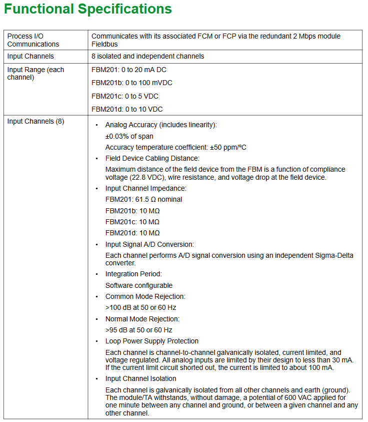
The FBM201 series includes 4 sub models, with the core difference being the supported analog input signal range, which can be flexibly selected according to the type of sensor on site:

Model input signal range key adaptive sensor

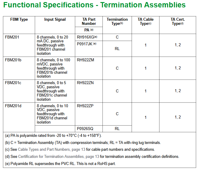
FBM201 0-20 mA DC (compatible with 4-20 mA industrial standard signal) 4-20 mA two-wire/four wire transmitter (such as pressure transmitter, liquid level transmitter)

FBM201b 0-100 mV DC millivolt level signal sensor (such as strain gauges, thermocouple signal conditioning output)

FBM201c 0-5 V DC 0-5 V voltage output sensor (such as some temperature sensors, concentration sensors)

FBM201d 0-10V DC 0-10V voltage output sensor (such as high-precision flow sensor, displacement sensor)

Core technical specifications and performance parameters

(1) Input channel and signal conversion

Category specific parameter description

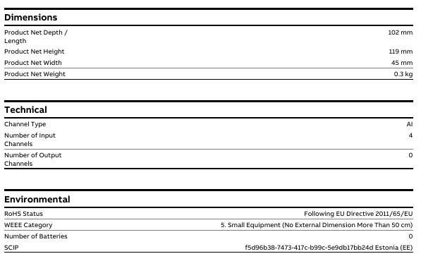
Number of channels: 8 independent channels. Each channel can be separately connected to different types of sensors (matching corresponding module models), and the channels do not interfere with each other

Isolation design between channels and between channels and ground: Galvanically isolated. The isolation voltage reaches 600 VAC (1-minute withstand), effectively suppressing electromagnetic interference (EMI) in industrial sites and preventing signal crosstalk and grounding loop problems

The signal conversion is independent for each channel. The sigma delta (∑ – Δ) A/D converter has a fast conversion rate and can update the analog input reading once every 25 ms; Support software configuration integration cycle, filter out process noise and electromagnetic noise, and improve data stability

Measurement accuracy ± 0.03% range (including linear error), temperature coefficient ± 50 ppm/℃. High precision conversion ensures the reliability of collected data. A low temperature coefficient means that accuracy degradation is small when the ambient temperature changes (such as -20-70 ℃ in industrial sites)

Input impedance – FBM201 (current input): 61.5 Ω (nominal)

-FBM201b/c/d (voltage/millivolt input): 10 M Ω current input impedance low, matching 4-20 mA transmitter load requirements; High voltage input impedance to avoid attenuation of sensor output signals

(2) Electrical and environmental adaptability
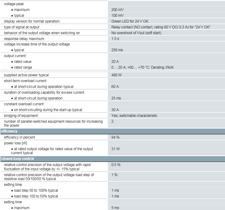
Power requirements:

Input voltage: 24 VDC redundant power supply (+5%/-10% fluctuation tolerance), supporting dual independent power supplies to ensure uninterrupted operation of the module;

Power consumption: 7 W (nominal), heat dissipation 3 W (maximum), low-power design reduces control cabinet heat dissipation pressure.

Environmental specifications:

Working temperature: -20-70 ℃ (-4-158 ° F), storage temperature -30-85 ℃;

Humidity: 5% -95% (without condensation);

Vibration and impact: 0.75 g (5-500 Hz), in compliance with industrial grade anti vibration standards;

Environmental level: Meets the requirements of ISA S71.04 Class G3 (Harsh, harsh environment), and can withstand complex industrial site conditions such as dust, humidity fluctuations, and sudden temperature changes.

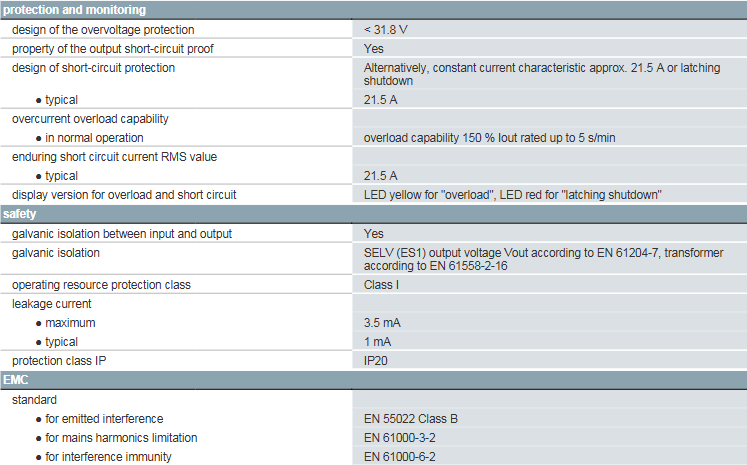
Anti interference capability:

Common mode rejection ratio (CMRR):>100 dB (50/60 Hz);

Differential Mode Rejection Ratio (NMRR):>95 dB (50/60 Hz);

Compliant with EN 61326-1:2013 Class A electromagnetic compatibility (EMC) standard, with strong resistance to electromagnetic radiation and conducted interference.

Hardware design and installation configuration

(1) Hardware structure characteristics

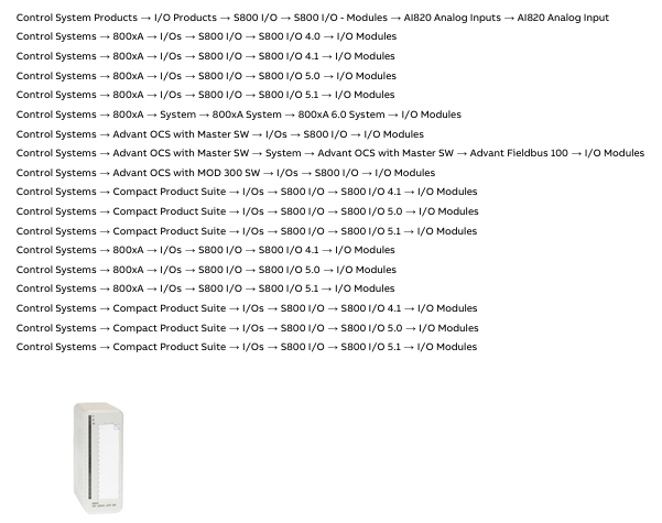
Physical protection: Adopting extruded aluminum alloy shell with high mechanical strength, it can protect internal circuits from physical impact and dust intrusion;

Hot swappable design: supports online removal/replacement (Hot Swap), without disconnecting on-site wiring, power or communication cables, reducing system downtime and improving maintenance convenience;

Status indication: The front of the module is integrated with LED indicator lights, which can intuitively display the power status, communication status, and channel fault status (such as overcurrent and signal abnormality), making it easy to quickly troubleshoot problems;

Redundant communication: Communicate with DCS controller (FCP/FCM) through a 2 Mbps redundant fieldbus, supporting A/B dual path switching. If one path fails, it will automatically switch to the other, ensuring uninterrupted data transmission.

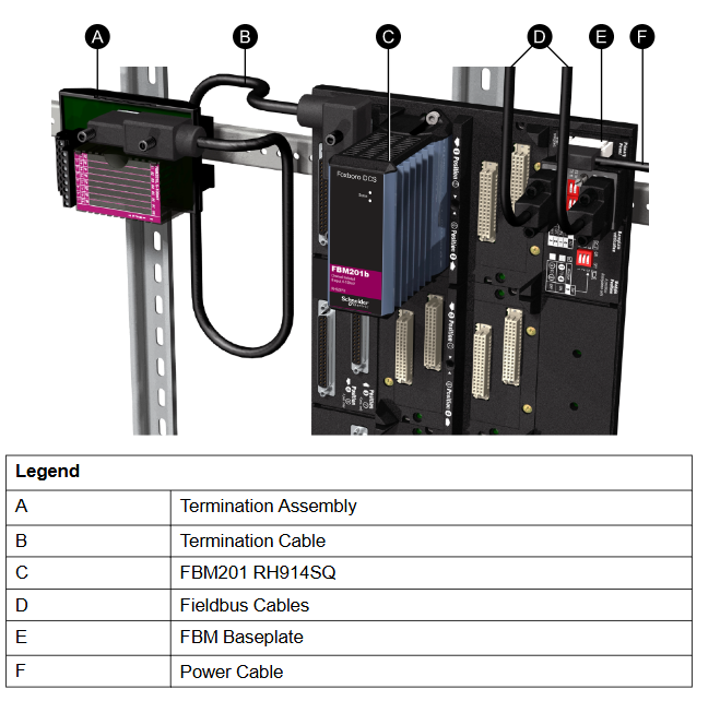
(2) Installation and wiring configuration

Installation method:

The module needs to be installed on a modular base plate (FBM Baseplate), which supports DIN rail installation (horizontal/vertical) or 19 inch rack installation (requires installation kit);

A single bottom plate can accommodate up to 4 or 8 FBM modules, supporting dense layout of multiple modules and saving control cabinet space.

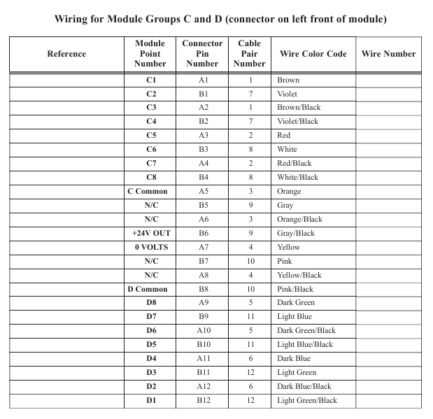
Wiring and Terminal Components (TA):

The on-site wiring is connected to the Terminal Assembly (TA) module installed through DIN rails. TA is divided into “Compression Terminal Type (C)” and “Ring Terminal Type (RL)”, suitable for different wire types (solid/multi strand wire);

The TA is connected to the module through a termination cable, which can be made of polyurethane (P/PVC) or low smoke halogen-free (LSZH), with a length of 0.5-30 meters (1.6-98.4 feet), and supports local or remote wiring (such as installing TA in adjacent control cabinets to reduce on-site wiring length);

Wire specifications: Compression terminals support 0.2-4 mm ² (24-12 AWG) wires, while ring terminals support 0.5-4 mm ² (22-12 AWG) wires, suitable for most industrial wiring needs.

Compliance certification and security features

(1) Compliance certification

Specific standard specifications for certification categories

Safety Certification – UL/UL-C: Class I, Groups A-D, Division 2 (Hazardous Areas), Temperature Class T4

-European Low Voltage Directive (2014/35/EU)

-ATEX 94/9/EC: II 3 G Ex nA [nL] IIC T4 (Zone 2 explosion-proof area)

-IECEx certification can be used in flammable and explosive environments (such as Zone 2 in petrochemical workshops), meeting major global industrial safety standards and adapting to cross-border project requirements

Environmentally compliant EU RoHS Directive (2011/65/EU, including amendments 2015/863, 2017/2102) does not contain harmful substances such as lead and mercury, meets environmental requirements, and is suitable for industries with high environmental standards (such as food processing and pharmaceutical manufacturing)

Electromagnetic compatibility (EMC) European EMC Directive (2014/30/EU), compliant with EN 61326-1:2013 Class A in industrial strong electromagnetic environments (such as near motors and frequency converters), with low module radiation and strong anti-interference ability, ensuring signal stability

(2) Security protection function

Overcurrent protection: Each channel is designed with a current limiting circuit, which limits the current to less than 30 mA during normal operation and approximately 100 mA during short circuits to prevent damage to sensors or modules due to overcurrent;

Voltage limit: It is prohibited to connect voltage signals exceeding 30 VAC or 60 VDC to avoid violating electrical safety regulations and prevent personnel from getting electric shock and module burnout;

Class 2 Circuit Certification: Communication circuits comply with the Class 2 circuit requirements of the National Electrical Code (NFPA 70 Article 725) and the Canadian Electrical Code (CSA C22.1 Section 16), and are classified as limited energy circuits with high safety.

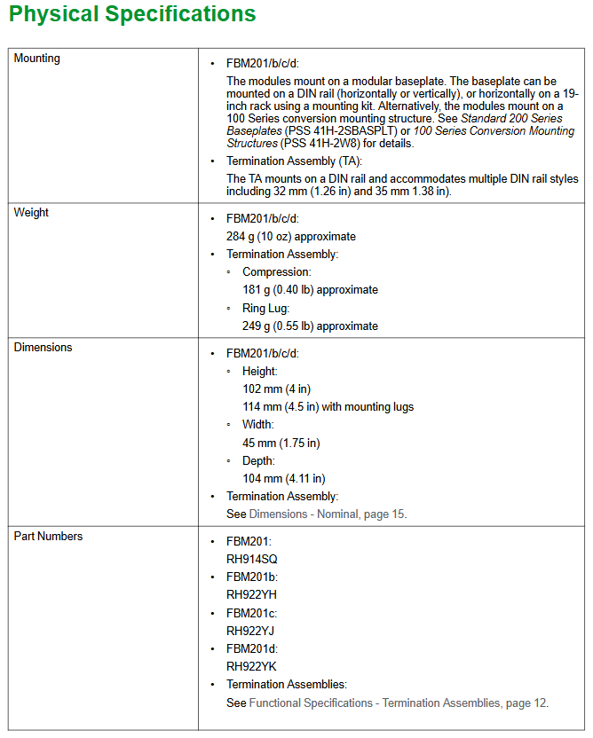
Model and accessory ordering information

(1) Core product model

Product type and model description

Analog input module FBM201 0-20 mA DC input

FBM201b 0-100 mV DC input

FBM201c 0-5 V DC input

FBM201d 0-10V DC input

Terminal component (TA) RH916XG (FBM201, compression terminal) is compatible with 8 current inputs of FBM201 and has compression wiring

P0917JK (FBM201, ring terminal) is compatible with the 8-channel current input of FBM201 and has a ring terminal

RH922ZM (FBM201b, compression terminal) is compatible with the 8-channel millivolt input of FBM201b and has compression wiring

RH922ZN (FBM201c, compression terminal) is compatible with 8-channel 0-5V input of FBM201c, with compression wiring

RH922ZP (FBM201d, compression terminal) is compatible with 8 channels of 0-10V input of FBM201d, with compression wiring

P0926SQ (FBM201d, ring terminal) is compatible with the 8-channel 0-10V input of FBM201d and has a ring terminal

(2) Terminal cable selection

Terminal cables are used to connect TA and FBM modules, classified by material and length, with the following core models:

Cable Material Length (meters/feet) Model (P/PVC material) Model (LSZH material)

Polyurethane (P/PVC) 0.5/1.6 RH916DA RH928AA

Low Smoke Zero Halogen (LSZH) 1.0/3.2 RH916DB RH928AB

2.0/6.6 RH931RM RH928AC

3.0/9.8 RH916DC RH928AD

5.0/16.4 RH916DD RH928AE

10.0/32.8 RH916DE RH928AF

15.0/49.2 RH916DF RH928AG

20.0/65.6 RH916DG RH928AH

25.0/82.0 RH916DH RH928AJ

30.0/98.4 RH916DJ RH928AK

Note: LSZH material cables have low smoke and no halogen release during combustion, making them suitable for scenarios with high fire safety requirements (such as underground factories and enclosed spaces).

Eaton XV-440-10TVB-1-20 Human Machine Interface (HMI)

Core positioning and basic information of the product

Eaton XV-440-10TVB-1-20 (catalog number 139906) is a 10.4-inch human-machine interface (HMI-PLC) with integrated PLC functionality in the Eaton XV400 series, positioned as an “operation control+data interaction” terminal in industrial automation scenarios. It combines visual monitoring and logical control capabilities, and can directly communicate with on-site devices such as sensors, drivers, and PLCs to achieve equipment status display, parameter settings, fault alarms, and simple logical control. It is suitable for manufacturing production lines, mechanical equipment control, process automation, and other scenarios.

This product should pay attention to the * * “Non New Application Recommendation” * * label, which is more suitable for upgrading or replacing existing systems, rather than the preferred model for brand new projects.

Core hardware and display specifications

(1) Display and Touch Configuration

Category specific parameter description

Display screen type: 10.4-inch TFT color LCD screen with a diagonal of 10.4 inches, supporting portrait installation, suitable for different control cabinet layouts

VGA resolution (640 × 480 pixels) meets the clear display requirements of equipment status, parameters, and curves in industrial scenes

Color and contrast can be adjusted to 65536 or 256 colors, with a contrast ratio of 350:1 for high color richness. The 350:1 contrast ratio ensures visibility in strong light or industrial environments

Brightness and backlight of 350 cd/m ², moderate brightness of LED backlight (software adjustable), LED backlight lifespan of up to 50000 hours, reducing maintenance costs in the later stage

Touch technology infrared (IR) touch, coupled with anti reflective laminated safety glass, has sensitive touch response. The anti reflective glass is suitable for strong light environments in the workshop, and the safety glass enhances impact resistance

(2) Core hardware parameters

Category specific parameter description

32-bit RISC CPU with a main frequency of 400 MHz ensures smooth switching of HMI interface and efficient operation of PLC logic

Memory Configuration – Internal DRAM: 64 MB (for operating system, programs, and data)

-Flash storage: approximately 1.5 MB (data backup)

-NVRAM: Approximately 32 KB (critical data is retained during power outages). The memory combination balances running speed and data security, and NVRAM ensures that parameters are not lost after power outages

External storage requires 2 CompactFlash (CF) card slots (supporting Type I/II) to be used in conjunction with CF cards for installing operating systems, storing applications, and historical data

Heat dissipation and power consumption – Power consumption: rated 14 W, maximum 32 W

-Heat dissipation: 32 W (control cabinet heat dissipation design needs to be considered) Low power design, but if communication modules or USB devices are installed, additional heat dissipation space needs to be reserved

Physical specifications – Weight: 4.1 kg

-Protection level: IP65 on the front (dustproof and waterproof), IP20 on the back (to be installed inside the control cabinet)

-Installation method: flush mounting, front four hole fixed IP65 front protection suitable for industrial dust and oil environments, embedded installation saves control cabinet space

Communication interface and protocol support

(1) Built in interface (standard)

Number and specifications of interface types, functional purposes

One 100Base TX/10Base-T Ethernet interface is used to connect to an upper computer (such as a computer), PLC, or industrial Ethernet network for remote data transmission and monitoring

RS-232 1 (9-pin SUB-D plug, non isolated) connected to serial devices (such as printers, barcode scanners, old-fashioned PLCs)

One CAN bus (9-pin SUB-D plug, globally isolated) supports CAN/EasyNet protocol and connects CAN bus devices (such as drivers and sensors). The isolation design enhances anti-interference performance

USB -1 USB 2.0 host interface (non isolated)

-One USB 1.1 device interface (non isolated) host interface can be connected to a USB flash drive (data export), mouse/keyboard (auxiliary operation); The device interface is used for communication with a computer (program download)

Expansion slots with 2 communication module slots (optional plugins) can be equipped with dedicated communication modules such as PROFIBUS and DeviceNet according to needs, expanding compatibility

(2) Supported industrial protocols

This product supports multiple mainstream industrial protocols through hardware interfaces and software configurations, ensuring compatibility with devices of different brands. The core protocols include:

Ethernet protocols: TCP/IP, EtherNet/IP

Bus protocols: CAN, PROFIBUS, DeviceNet, KNX, MODBUS

Serial protocol: Standard serial protocol corresponding to RS-232 (such as ASCII, RTU)

Note: Some agreements require the installation of communication modules or the purchase of corresponding software licenses.

Software and Function Configuration

(1) Operating System and Programming Software

Category specific requirements description

The operating system Windows CE requires installation through a CF card and a separate Windows CE license must be purchased

The HMI visualization software GALILEO EPAM is used to design HMI interfaces (such as device status screens, parameter settings windows, alarm pages), supporting graphical drag and drop operations

The PLC programming software XSOFT-CODESYS-2 or XSOFT-CODESSYS-3 complies with the IEC 61131-3 standard and supports five programming languages, including ladder diagram (LD) and functional block diagram (FBD), for writing PLC logic control programs

PLC function activation requires the purchase of a license (model: 140390 LIC-PLC-MXP-MEDIUM). The standard configuration does not include PLC function, and users need to purchase and install a separate license before activating the logic control

(2) Core functions

HMI visualization function:

Support switching between 100 online languages and adapt to multilingual workshop environments;

200 level password permission management to prevent unauthorized personnel from modifying key parameters;

Equipped with a messaging system (including buffer and confirmation functions), it can display real-time device fault alarms;

Supports recipe management, historical data recording, and printer output (requires USB printer connection).

PLC control function (activated):

Support 79 × 59 logical channels, which can achieve simple logic control (such as device start stop, interlock protection);

Compatible with CODESYS programming environment, the program can be downloaded to the device via USB or Ethernet.

Environmental adaptability and compliance certification

(1) Environmental parameters

Category specification description

The working temperature is between 0 ° C and 50 ° C, and it is necessary to ensure that the temperature inside the control cabinet does not exceed 50 ° C to avoid equipment failure caused by high temperature

Storage/transportation temperature -20 ° C~60 ° C meets the temperature requirements of industrial logistics and warehouse storage

Relative humidity of 10%~95% (non condensing) is suitable for humid workshop environments (such as food processing and chemical industry), but direct contact with condensed water should be avoided

Anti interference and protection – Mechanical shock: compliant with IEC 60068-2-27 standard

-Vibration: Complies with IEC 60068-2-6 standard

-EMC electromagnetic compatibility: EN 61000-6-2/3/4 anti impact and vibration design enhances equipment durability, EMC compliance ensures stable operation in industrial strong electromagnetic environments

(2) Compliance certification

Safety certifications: UL 508, cUL (North American market), IEC/EN 61131-2, EN 60950 (electrical safety);

Explosion proof certification: ATEX 94/9/EC II 3D Ex II T70 ° C IP5x (applicable to Zone 22 area, dust explosion-proof);

CE certification: Complies with EMC and low voltage directives, and can be sold in the EU market.

Accessories and ordering information

(1) Essential accessories

Accessory type, model/specification, and purpose

CompactFlash (CF) card Type I/II (capacity needs to meet operating system and program requirements) for installing Windows CE system, storing HMI projects and PLC programs

PLC license 140390 LIC-PLC-MXP-MEDIUM activates the PLC control function of the device

Power supply 24 V DC SELV (safe extra low voltage), voltage range 20.4-28.8 V DC, requires a separate industrial power supply that meets specifications to ensure stable power supply to the equipment

(2) Optional accessories

Accessory type, model/specification, and purpose

The communication module is compatible with the XV400 series PROFIBUS/DeviceNet module expansion bus interface, connecting more types of field devices

Ethernet cable (100Base TX), RS-232 cable, CAN bus cable, communication connection between equipment

Install the attachment with four hole fixing screws and embedded mounting brackets to assist in the fixed installation of equipment

(3) Product Model Interpretation

Taking “XV-440-10TVB-1-20” as an example, the key parameter meanings are:

10 “: 10.4-inch display screen;

TVB: Touch type (infrared touch)+interface configuration (including CAN and Ethernet);

1-20 “: Hardware version and compliance label.

Bentley Baker Hughes 2300 Series Vibration Monitors

Product core positioning and application scenarios

The 2300 series vibration monitor is an industrial grade online vibration monitoring device launched by Baker Hughes. Its core function is to real-time collect and analyze vibration data of rotating machinery (such as motors, pumps, compressors, turbines, etc.), accurately monitor vibration amplitude and frequency, timely identify abnormal vibration states of equipment, trigger alarms or shutdown protection, ultimately prevent mechanical failures, extend equipment life, and ensure the continuity and safety of industrial production processes. Its typical application scenarios cover fields such as oil and gas, chemical, power, manufacturing, etc., and are suitable for 24-hour uninterrupted status monitoring of key rotating equipment.

Product Model and Core Classification

The 2300 series includes multiple sub models, which can be divided into two core categories based on monitoring functions and signal types to meet different monitoring needs:

Model Category Core Monitoring Parameters Key Features Applicable Scenarios

2301/2302 single channel vibration monitor 2301: Radial vibration (Velocity/Displacement); 2302: Axial vibration (Thrust Position) single channel independent monitoring, supports 4-20mA analog output, can be configured with local alarm lights, compact structure, only needs to monitor equipment with a single vibration dimension (such as small motor radial vibration, pump axial thrust monitoring)

2303 dual channel vibration monitor simultaneously monitors 2-path vibration (Velocity/Displacement), or 1-path+1-path axial vibration. The dual channel integrated design reduces installation space and supports vibration difference monitoring (such as wheel misalignment analysis). The alarm logic is more flexible and critical equipment that requires simultaneous monitoring of multidimensional vibration (such as radial and axial joint monitoring of compressors and turbines) needs to be monitored simultaneously

Technical specifications and performance parameters

(1) Core parameters for vibration monitoring

Specific specifications for parameter categories

Measurement range velocity: 0-20 mm/s (RMS, RMS); Displacement: 0-200 μ m (peak to peak, PP); Axial position (Thrust): 0-500 μ m (peak to peak) supports users to customize the range according to device types (such as low-speed motors, high-speed turbines), meeting the vibration characteristics requirements of different devices

Frequency response 5-1000 Hz (standard range); Optional 1-1000 Hz (low-frequency extension) covers the vibration frequency range of the vast majority of industrial rotating equipment (such as motor frequency vibration, bearing fault high-frequency vibration), ensuring the integrity of monitoring data

Accuracy level ± 2% of full scale (at 25 ℃ ambient temperature); ± 3% full range (0-60 ℃ working temperature range) high measurement accuracy ensures the accuracy of abnormal vibration identification, avoiding false alarms or missed alarms

Input signal type compatible with ICP ®  Type accelerometer (with built-in charge amplifier, requiring 24V DC excitation); Or piezoelectric acceleration sensors (requiring external charge amplifiers) support mainstream industrial vibration sensors, reducing the compatibility cost of upgrading or replacing user devices

(2) Electrical and Environmental Specifications

Power requirements: 18-30V DC (standard), or 85-265V AC (optional AC power supply module), power consumption ≤ 5W (no alarm state), with overvoltage and overcurrent protection functions, suitable for unstable power supply environments in industrial sites.

Output signal:

Analog output: 4-20mA isolated output (independent for each channel), load resistance 0-500 Ω, can be directly connected to DCS, PLC or SCADA system for remote data monitoring.

Switching output: 2 sets of SPDT (single pole double throw) relay outputs (1 set per channel/monitoring dimension), rated load 250V AC/5A or 30V DC/5A, used for local alarm (such as sound and light alarm lights) or equipment shutdown control.

Environmental adaptability: working temperature -20-60 ℃, storage temperature -40-85 ℃, relative humidity 0-95% (no condensation), protection level IP65 (panel installation part), can withstand harsh conditions such as dust, humidity, and vibration in industrial sites.

Installation method: Panel embedded installation (standard 1/4 DIN size, i.e. 96 × 48mm panel opening), installation depth ≤ 150mm, suitable for compact layout inside control cabinets.

Core functions and operational design

(1) Monitoring and protection functions

Multi level alarm setting: Supports 2-level alarm thresholds (“Warning”, “Danger”), users can configure specific values through panel buttons or software (such as speed warning value of 10 mm/s, danger value of 15 mm/s), alarm status triggers external response through relay output, and panel LED lights (red=danger, yellow=warning, green=normal) intuitively display device status.

Vibration trend recording: Some models have built-in data storage function, which can record the maximum and average vibration trend in the past 30 days (sampling interval can be set between 1-60 minutes). It supports exporting data through RS485 communication (Modbus RTU protocol) for equipment fault tracing and life prediction analysis.

Fault diagnosis assistance: Some high terminal models (such as 2303-D) support vibration frequency spectrum analysis (with specialized software), which can identify common fault characteristic frequencies (such as bearing inner ring fault frequency, unbalanced vibration frequency), helping operation and maintenance personnel locate the root cause of the fault (such as “imbalance”, “misalignment”, “bearing wear”).

(2) Operation and Configuration

Local operation: The panel is equipped with 4 tact buttons (menu, confirm, increase/decrease), paired with a 2-line 16 character LCD display screen, which can directly set parameters such as range, alarm threshold, sampling interval, etc. without the need for external tools, making it convenient for on-site debugging.

Remote configuration: Supports connecting to upper computers (such as computers and HMIs) through RS485 communication interface (Modbus RTU protocol), using Baker Hughes dedicated configuration software (such as “VibroLink”) for parameter settings, data reading, and trend analysis, suitable for centralized management of batch devices.

Hardware Design and Accessories

(1) Hardware structure characteristics

Isolation design: Optoelectronic isolation (isolation voltage 2500V AC, 1 minute) is used between input signals, analog output, and power supply to effectively suppress electromagnetic interference (EMI) in industrial sites, ensure stable monitoring data, and avoid misoperation caused by external interference.

Redundancy protection: The relay output has a “Fail Safe” mode, which can be set to “alarm when power is off” or “normal when power is off” to prevent the device from losing protection due to monitor power failure; Some models support sensor open/short circuit detection. When the sensor fails, it immediately triggers a “sensor failure” alarm, prompting operation and maintenance personnel to troubleshoot.

(2) Supporting accessories

Sensor: Recommended to be paired with Baker Hughes 3300 series ICP ®  Acceleration sensors (such as 330103 radial sensors and 330180 axial sensors) provide a complete solution of “monitor+sensor” to ensure signal matching and stability.

Communication and connection accessories: Provide RS485 communication cables (model 2300-CAB), sensor extension cables (model 3300-CAB), and panel mounting brackets (model 2300-MNT) to simplify on-site installation and wiring.

Allen-Bradley IMC ™  S Class Compact Motion Controllers

Core positioning and basic functions of the product

IMC-S/23x is a compact, robust microprocessor based motion controller under Rockwell Automation Allen Bradley, supporting 2-axis or 4-axis servo control, integrating logic and field power, and can be used as an independent motion and logic controller without additional accessories, suitable for various industrial scenarios. Its core function revolves around closed-loop motion control, which requires external drive systems and feedback encoders to achieve various high-precision motion controls, including:

Single point positioning control: supports three speed profiles: trapezoidal, parabolic, and S-shaped, and can independently program speed, acceleration, and deceleration parameters to meet smooth start stop requirements under different operating conditions.

Multi axis interpolation function: Supports up to 3-axis linkage, achieving linear, circular, and spiral interpolation, suitable for complex trajectory motion scenes (such as precision machining path control).

Synchronous control capability: equipped with electronic gear and electronic cam functions, the electronic gear can make any shaft follow the main axis in a programmable proportion (proportion supports floating point or fractional form); Electronic cam can generate collaborative motion profiles based on time or main axis position, and can also be combined with phase shift, automatic positioning, and automatic correction functions to simplify complex synchronous motion programming.

Hardware configuration and specifications

(1) Core hardware parameters

Category specific parameters

The microprocessor Intel 80960SB operates at a frequency of 16MHz and adopts RISC architecture to ensure high-speed data processing and motion computing

Axis configuration includes 2 axes (IMC-S/232 model) and 4 axes (IMC-S/234 model)

Feedback and output encoder input supports incremental AB orthogonal signals, with a maximum feedback count rate of 4MHz, ensuring accuracy under high-speed motion; The servo output is an isolated 16 bit DAC, supporting ± 10V voltage or ± 150mA current mode, and can be independently configured by axis

Storage configuration applications and parameter storage use RAM (non-volatile) with battery backup, with a battery life of at least 10 years; Can store 32K applications, 13000 main cam points+13000 slave cam points, support 2000 64 bit floating-point user variables

Environmental adaptability: Operating temperature range of 0-50 ℃, storage temperature range of -40-70 ℃, maximum humidity of 95% (non condensing), suitable for complex industrial environments

Power requirements: AC input 90-132V/175-264V (47-63Hz, maximum 3A), I/O power supply 5-40V DC (nominal 24V DC, maximum 3A), all equipped with 3A slow melting fuse protection

(2) I/O interface configuration

The dedicated discrete I/O: 2-axis model includes 10 inputs (5 per axis, corresponding to origin switch, positive and negative overtravel switch, driver fault, position positioning signal) and 4 outputs (2 per axis, corresponding to driver enable, absolute position trigger); The 4-axis model has 20 inputs and 8 outputs, all of which are designed with optical isolation. The output includes relay contacts (driver enabled) and solid-state relays (position triggered).

Extended I/O support: can directly connect up to 8 Allen Bradley Flex devices ™  I/O module, with a total of 128 discrete I/O points, can also be replaced with analog I/O modules (such as 8-channel analog input and 4-channel analog output modules) to meet different signal acquisition and control requirements, and can be directly connected without the need for additional adapters for use.

Software and Programming

(1) Programming environment

Using Allen Bradley’s proprietary GML (Graphic Motion Control Language) for application programming, providing over 100 instructions and allowing for complete customization of controller functions; Equipped with a graphical development system, it supports real-time debugging, reduces programming difficulty, and supports multitasking operating systems. It can execute up to 10 tasks simultaneously, improving system efficiency.

(2) Program Download and Storage

Download programs to the controller through RS-232C or RS-422 ports, store them in non-volatile RAM, and have a “Memory Lock” key switch on the panel to prevent accidental operation or unauthorized modification of programs and parameters.

Communication function

The controller is equipped with multi-channel communication interfaces, supporting flexible interconnection with external devices, including:

Serial communication: 2 serial ports (A/B), can be independently configured as RS-232C or RS-422 (optical isolation), RS-232C has a maximum baud rate of 19.2k, RS-422 has a maximum baud rate of 128k; port B can be replaced with DH-485 channel (half duplex, baud rate of 9.6k/19.2k, RJ-45 interface), used for human-machine interface (MMI) connection, supports ASCII encoding and XON/XOFF flow control.

Remote I/O option (IMC-S/23x-R model): Supports remote I/O communication with other Allen Bradley devices (such as PLCs), supports discrete signal and block transmission, with a maximum block transmission length of 64 words (128 bytes), and supports multiple data formats such as 32-bit integers and 32-bit floating-point numbers; The rack address can be selected between 0-31, and the rack width supports 1/4, 1/2, 3/4, and full rack configurations, corresponding to different I/O points (such as a full rack with 100 inputs and 100 outputs).

AxisLink option (IMC-S/23x-L model): used for real-time axis collaboration between multiple controllers, supports 1Mbps baud rate, uses Allen Bradley 1770-CD RIO cable (or equivalent cable), with a maximum total cable length of 25 meters (minimum 1 meter between controllers); Up to 8 controllers can be connected (32 axes in total, with expansion nodes supporting 16 controllers and 64 axes), supporting virtual spindle functionality (up to 1 controller per controller for a total of 4), with a maximum of 31 slave axes per virtual spindle, and a discrete I/O response time of ≤ 1ms.

Model and accessories

(1) Model Interpretation

In the IMC-S/23x model format, the meanings of each part are as follows:

2 “: Represents a Stand Alone platform;

3 “: represents Compact Package;

Axis number: “2” represents 2 axes, “4” represents 4 axes;

Options: “R” represents Remote I/O adapter, “L” represents AxisLink multi axis synchronous link.

(2) Specialized cable accessories

Provide pre designed cable components to simplify external device connections. Common cables are listed in the table below:

Product catalog number, usage, length (feet/meters), required quantity per device

4100-CCF1/4100-CCF3 connection Flex I/O module 1/0.3, 3/1, 1 per controller (only required when using Flex I/O)

4100-CCS15F connects servo drive and feedback device 15/4.5, 1 per axis

410P-CAQB connection 1391B-ES/1391-DES driver with no fixed length, 1 per axis

4100-CCA15F connection dedicated discrete I/O 15/4.5, 1 per axis

4100-CCW15F connected CPU watchdog 15/4.5, 1 per controller

4100-RCS3T connection 4100-REC 3/1, 1 per axis (only required when using 4100-REC)

Safety and Diagnosis

Security protection function: equipped with encoder loss detection (to prevent feedback faults from causing equipment damage), programmable position locking and position error tolerance (servo fault protection), software direction travel limit (to prevent overtravel); The CPU watchdog is equipped with a panel LED indicator to ensure timely alarm in case of system failure.

Diagnosis and debugging: Built in hook up diagnostic function and automatic servo setting program, which can quickly complete servo parameter self-tuning; The panel LED can intuitively display the status of power, memory, etc., simplifying troubleshooting.

Siemens 6AV7875-0BC20-1AC0 SIMATIC HMI

Product Core Basic Information and Positioning

Basic identification and functional positioning

Specific project content

Ordering Number 6AV7875-0BC20-1AC0

Product Name SIMATIC HMI Software License

Core functions unlock specific advanced features of SIMATIC HMI software (such as data archiving, advanced alarm management, multilingual support, etc., specific functions need to be confirmed in conjunction with the supporting software version), without physical hardware, only providing authorization keys for function activation

The adaptation software series is mainly compatible with SIMATIC WinCC series HMI configuration software (such as WinCC Comfort, WinCC Advanced, WinCC Professional), and needs to be matched with specific software versions (the document does not specify the minimum version, it is recommended to refer to Siemens compatibility list)

Key authorization features and technical parameters

1. Authorization type and delivery form

The authorization adopts the form of “soft authorization”, without physical media, and activates functions through digital keys. The specific characteristics are as follows:

Authorization Characteristics Specific Specifications

Authorization type: Single User License, limited to devices/software instances bound by authorization, does not support multi device sharing

Delivery form – electronic delivery: send the license key and activation guide via email;

-Optional physical carrier: In some scenarios, a USB encryption dongle (requires additional confirmation, not clearly marked in the document) is provided to store authorization information and prevent authorization loss

The activation method is through Siemens’ official authorization management tool (such as Automation License Manager), and the authorization legality needs to be verified online (some scenarios support offline activation, and an offline activation file needs to be applied for)

Perpetual License, with no usage time limit after activation, is only supported by the software version lifecycle (if the supporting software stops maintenance, the authorization function may not be available in the new version)

2. Function unlocking range (typical, subject to actual software adaptation)

The document does not explicitly list all the functions unlocked by this authorization, but based on Siemens’ similar HMI authorization logic, it is speculated that the core unlocking functions include:

Data archiving enhancement: Unlock high-capacity data archiving functions (such as long-term storage of historical process data, archive file compression and encryption), support archive data export (such as CSV, Excel format) for offline analysis;

Advanced alarm management: Expand alarm capacity (such as supporting tens of thousands of alarm records), increase alarm priority grading (such as emergency/important/general/prompt four levels), support alarm related process parameter traceability;

Multilingualism and Localization: Unlock over 32 project languages and 16 online running languages, support real-time language switching, and adapt to multi nationality workshop operation scenarios;

Remote access support: Allow remote monitoring of HMI interface through industrial Ethernet (with hardware network environment), support remote parameter modification and fault diagnosis, without on-site operation;

Script and custom logic: Open advanced script editing functions (such as VBScript, C script), allowing users to write custom control logic (such as complex process calculations, equipment linkage control), enhancing the flexibility of HMI systems.

Adaptation environment and compatibility

1. Hardware adaptation range

Authorization does not have independent hardware requirements and only relies on supporting HMI devices or computer hardware running software. Typical adaptation scenarios include:

SIMATIC HMI panels, such as Comfort Panel, Mobile Panel, and Tablet Panel, must ensure that the panel hardware supports the corresponding software version;

Industrial PC/Workstation: Industrial computers running WinCC series software must meet the minimum hardware configuration of the software (such as CPU, memory, hard disk space, refer to the requirements of the supporting software for details);

Virtualization environment: Some scenarios support activation in virtualization platforms such as VMware and Hyper-V. It is necessary to confirm authorization to support virtualization deployment (the document is not clear, please consult Siemens technical support).

2. Software version compatibility

Minimum compatible software version: The document does not clearly indicate it. It is recommended to use WinCC V13 or above (Siemens’ mainstream HMI software version in recent years), as lower version software may not recognize this authorization;

Operating system compatibility: Supports Windows industrial version operating systems (such as Windows 10 IoT Enterprise, Windows Server series), which must be consistent with the operating system requirements of the supporting WinCC software, and does not support home version Windows systems.

Siemens 6AV6645-0CB01-0AX0 Mobile Panel

Product Core Basic Information and Positioning

Basic identification and functional positioning

Specific project content

Ordering Number 6AV6645-0CB01-0AX0 (core ordering identifier, belonging to SIMATIC MOBILE PANEL series mobile HMI)

Product Name SIMATIC MOBILE PANEL 277 (7.5-inch mobile panel, integrated enable button and emergency stop button, meeting safety operation requirements)

Core functions include human-machine interaction in industrial sites, supporting equipment monitoring (such as process parameter display and alarm viewing), operation control (such as parameter input and instruction issuance), and adapting to mobile operation scenarios (such as production line inspection and equipment debugging)

The compatibility of the configuration tool supports two types of mainstream configuration software:

-WinCC flexible: Standard Version 2005 SP1 and above, Advanced version;

-TIA Portal: Comfort, Advanced, Professional versions (V11 and above), Basic version not supported

Key hardware and display characteristics

Hardware and display performance directly affect the operating experience and on-site adaptability. The document specifies the core parameters in detail

1. Display system

Display specific specifications of parameters

Screen specifications – size: 7.5 inches (diagonal of screen);

-Type: TFT color LCD display screen;

-Resolution: 640 × 480 pixels (VGA level, meeting the clear display requirements of industrial parameters)

Color and Grayscale – Number of Colors: 65536 (True Color, Supports Rich Interface Design);

-Grayscale level: 65536, smooth transition of the image

Backlight lifespan MTBF (Mean Time Between Failures) is approximately 50000 hours (at 25 ℃), and long-term use does not require frequent backlight replacement

2. Operation control components

Supports “button+touch” dual operation mode, adapted to different industrial operation habits, and has safety control buttons:

Specific specifications of operating components

Function keys – Quantity: 18 programmable function keys, all with LED indicator lights (real-time display of key status, such as active/inactive);

-Features: Supports custom engraved film buttons, and can annotate functions according to needs (such as “start”, “stop”, “parameter settings”)

Touch function – type: analog resistive touch screen (industrial grade durability, supports glove operation);

-Calibration: Supports touch calibration function to ensure operational accuracy

Safety Button – Stop Button: Integrated, meets industrial safety standards, and can quickly cut off dangerous operations in emergency situations;

-Enabling Button: Integrated, requires pressing to activate operation, preventing accidental touch

Other inputs – supports numeric/alphabetical/hexadecimal input;

-Support 2 sets of multi key operations simultaneously to improve operational efficiency

3. Core hardware configuration

Specific specifications of hardware parameters

Processor ARM architecture, 520MHz main frequency (meets the interface refresh and data processing requirements of industrial HMI)

Storage Capacity – Main Memory (RAM): Maximum 128MB;

-User data available memory: 6MB;

-Extended Storage: Supports 1 MMC/SD card slot (expandable storage for archiving logs, backup configuration)

Real time clock hardware clock, with battery backup and support for synchronization (ensuring time accuracy for logging and task scheduling)

Communication interface and protocol compatibility

As an industrial HMI, it needs to communicate with multiple controllers and devices, and the documentation clearly states its rich interface and protocol support:

1. Physical interface

Specific specifications of interface type

Industrial bus interface -1 × RS422 (suitable for high-speed, long-distance serial communication, such as connecting encoders and frequency converters);

-1 × RS485 (supports multi device networking, such as connecting PLC and sensors);

-1 x Industrial Ethernet (RJ45 interface, maximum transmission rate of 12Mbit/s, used for high-speed data exchange)

Universal interface -1 x USB interface (supports connecting external devices such as mouse, keyboard, barcode reader, USB flash drive, etc.);

-No parallel interface

2. Support protocols

Covering mainstream industrial buses and Ethernet protocols, compatible with multiple brands of controllers:

Specific support for protocol categories

Ethernet Protocol – TCP/IP (Basic Network Protocol, used for configuring transmission and remote monitoring);

-PROFINET IO (Siemens Industrial Ethernet protocol, supporting real-time data exchange)

Serial bus protocol – PROFIBUS DP (Siemens mainstream fieldbus, connecting S7-300/400 and other PLCs);

-MODBUS (Universal Industrial Protocol, compatible with devices from brands such as Modicon and OMRON)

Other compatible supports AS-i, CAN, INTERBUS and other protocols (with corresponding drivers), can connect to multiple brands of controllers such as S5, S7-200/1200/1500, Allen Bradley, Mitsubishi, etc

Industrial environment adaptability and safety compliance

1. Environmental tolerance

Specific specifications of environmental parameters

Temperature range – Operating temperature: 0~+40 ℃ (suitable for most industrial workshop environments);

-Storage/transportation temperature: -20~+60 ℃, suitable for logistics and warehousing needs

Protection level: IP65 (dustproof, waterproof, suitable for use in humid and dusty industrial sites)

Drop resistance: Drop height of 1.2 meters (non packaged state, not easily damaged by accidental drop, improving on-site durability)

Maximum relative humidity tolerance of 80% (without condensation), suitable for high humidity environments (such as food processing and water treatment workshops)

2. Safety and compliance certification

Compliance category specific certification

Safety level – compliant with EN ISO 13849-1:2008 standard, performance level PL d (meeting industrial safety control requirements);

-Safety category complies with EN954-1 (for emergency stop and enable buttons)

International certifications CE (EU Access), cULus (US Canada Access), C-TICK (Australia Access), SIBE (German Safety Certification), supporting global use in multiple regions

Software functions and configuration features

1. Core software functions

Specific specifications for functional categories

Monitoring and Alarm – Supports 4000 alarm messages (including bit alarms and analog alarms), with 32 alarm levels;

-Equipped with an alarm log system (including caching and confirmation functions), capable of recording alarm time, type, parameters, and supporting 99 confirmation groups

Formula management – supports 300 formulas, each containing 500 data records, with 1000 entries per record;

-Formula storage: 64KB integrated Flash, expandable through MMC/SD card

Data archiving – supports 20 archive files, with a maximum of 10000 records per archive;

-Archive types: alarm archive, process value archive;

-Storage format: CSV (convenient for offline analysis using software such as Excel)

Variable management – supports 2048 device variables, with a maximum of 200 variables per screen;

-Support initial and limit value settings for variables, support Structs and date time types

2. Configuration and maintenance

Specific specifications of configuration features

Interface design – supports 500 configurable screens and dynamic objects (such as trend charts, bar charts, sliders);

-Supports 16 online running languages and 32 project languages, suitable for multilingual workshops

Data transmission – Configure transmission methods: MPI/PROFIBUS DP, USB, Ethernet, supporting automatic transmission recognition;

-Support Delta transfer to reduce configuration update time

The maintenance tool supports functions such as screen cleaning, touch calibration, backup/restore, device switching, etc., simplifying on-site maintenance

Physics and other parameters

Specific specifications of physical parameters

Size and weight – shell diameter: 290mm, depth: 103mm (circular design, easy to hold and install);

-Weight (unpackaged): 1.7kg, with good portability

The power supply is provided through a connection box (which needs to be paired with a Siemens dedicated connection box to ensure stable and safe power supply)

Warranty and Support – Warranty Period: 1 year;

-Support free hotline service and provide technical support

Siemens 6DD1607-0AA2 module

Product Core Basic Information and Positioning

Basic identification and functional positioning

Specific project content

Ordering Number 6DD1607-0AA2 (core ordering identifier, belonging to the FM458-1 DP application module of SIMATIC S7-400 series)

Product series SIMATIC S7-400 (Siemens high-end PLC series, suitable for complex industrial control requirements)

Module type FM458-1 DP Application Module (dedicated application module, supports PROFIBUS DP communication, can achieve high-precision and high real-time control tasks)

Complex control tasks in typical application scenarios of industrial automation, such as process control, motion control, synchronous control, etc., require data exchange with other devices (such as I/O modules, drivers) through the PROFIBUS DP bus

Key electrical and hardware parameters

1. Power supply characteristics

The stability of power supply directly affects the reliability of module operation. The document clearly indicates the requirements for dual voltage power supply and the range of current consumption:

Specific specifications of power supply parameters

Rated supply voltage -5V DC (core logic power supply);

-24V DC (auxiliary power supply, such as digital input circuit)

The allowable voltage range is 5V DC: 4.8V~5.25V (including ripple), ensuring that voltage fluctuations do not affect the core functions of the module; 24V DC does not specify the specific fluctuation range, please refer to the overall power supply specification of S7-400 system

Input current – typical consumption: 1.5A;

-Maximum consumption: 3A (to ensure that the system power capacity meets the requirements and avoid overload)

2. Storage and clock function

The module has data backup and real-time clock functions, supporting time correlation and data persistence of control tasks:

Specific specifications for functional categories

Storage backup – equipped with SRAM (Static Random Access Memory), supporting data backup;

-Backup battery: An external backup battery is required, with a maximum backup current of 15 μ A (low-power design to extend battery life)

Real Time Clock – Hardware Clock: Equipped with;

-Resolution: 500ms (can meet the time synchronization requirements of most industrial control scenarios)

3. Digital input interface

Provide 8 digital inputs for receiving external switch signals (such as sensor and button signals), with parameters adapted to industrial standard signals:

Specific specifications of digital input parameters

Input quantity of 8 channels, interface is Connector X2 (dedicated wiring terminal, corresponding cable needs to be matched)

Rated input voltage 24V DC (commonly used industrial DC signal voltage, compatible with most sensor outputs)

Signal logic – signal “0” (off): -1V~+6V;

-Signal “1” (conducting): 13.5V~33V (wide range design, strong resistance to voltage fluctuations)

Input current – signal “0” maximum static current: 0mA (no leakage current, to avoid false triggering);

-Typical current of signal “1”: 3mA (at 24V DC, low power consumption, reducing total system energy consumption)

Response time “0” → “1” (conduction) Maximum delay: 5 μ s (high-speed response, adapted to rapidly changing on-site signals)

Potential isolation does not have built-in potential isolation (Potential Separation: No), and isolation needs to be achieved through optional interface modules to avoid on-site interference entering the module’s interior

Communication and functional characteristics

1. PROFIBUS DP interface (core communication function)

As a key feature of the FM458-1 DP module, the PROFIBUS DP interface supports high real-time and high reliability industrial bus communication:

Specific specifications of communication parameters

Equidistance support and connection to Interrupt Tasks ensure stable time intervals for data transmission, meeting high-precision requirements such as synchronous control

Slave to Slave Communication support for direct data exchange between stations, without the need for forwarding through the main station, reducing data transmission latency and improving system response speed

2. Interruption and Diagnosis

The module has alarm and status feedback functions, which facilitate troubleshooting and system maintenance:

Alarm function: Supports sending fault alarm signals (such as module failures or communication abnormalities) to the PLC master station or upper computer through the PROFIBUS DP bus;

Diagnostic/Status Information: Provides module operation status information (such as power supply status, communication status) to assist technicians in quickly locating problems.

Physical and installation parameters

Specific specifications of physical parameters

Weight approximately 1000g (1kg, lightweight design, compatible with S7-400 base plate installation, no additional load-bearing burden)

Slot requirements require one slot on the S7-400 motherboard (Required Slot: 1), and installation must follow the motherboard slot numbering rules without special slot restrictions

GE IC693MDL655 Discrete Input Module

Product Core Basic Information and Positioning

Basic identification and functional positioning

Specific project content

Ordering Number IC693MDL655 (core ordering identifier, belonging to the I/O module series of GE Series 90-30 PLC)

Product Type 24V DC Positive and Negative Logic Discrete Input Module

The core function is to collect 32 discrete signals from industrial sites (such as on/off signals from sensors, limit switches, buttons, etc.), isolate them through optocouplers, and transmit them to the PLC logic side to achieve safe interaction between on-site signals and control systems

The adaptation system is only compatible with GE Series 90-30 PLC systems and can be installed in any I/O slot of the 5-slot or 10 slot baseboard

Key functional characteristics and electrical parameters

1. Core functional features

Input channel configuration: There are a total of 32 discrete inputs, divided into 4 independent isolation groups (A1-A8, B1-B8, C1 to C8, D1 to D8), with 8 inputs in each group. Each group has an independent common terminal (ACOM, BCOM, CCOM, DCOM) to avoid signal interference between groups;

Isolation design:

The on-site side and logic side are isolated by a photoelectric coupler to achieve 1500V, protecting the PLC core circuit from high-voltage/interference effects on site;

The isolation voltage between groups is 250V, further reducing signal crosstalk between different input groups;

Status indication: The top of the module is equipped with 32 LED indicator lights (corresponding to A1-A8 to D1-D8), which display the real-time on-off status (ON/OFF) of each input for easy troubleshooting;

Logical compatibility: Supports positive and negative logic inputs, adapts to field signals of different polarities, can withstand up to 30V DC input voltage, and adapts to fluctuations in industrial power grids.

2. Key electrical parameters

Parameter category specific specifications

Input voltage – rated voltage: 24V DC (positive and negative logic);

-Input range: 0~30V DC;

-On state voltage: 11.5~30V DC;

-Off state Voltage: 0~5V DC

Input current – typical conduction current (at 24V DC): 7.0mA;

-Minimum conduction current: 3.2mA;

-Maximum shutdown current: 1.1mA

Response time – On response time: maximum 2ms;

-Off response time: up to 2ms, meeting the requirements of fast signal acquisition

Power consumption – Backboard+5V bus power consumption: maximum 195mA (including 29mA basic power consumption+0.5mA per channel conduction+4.7mA per channel LED lighting);

-Isolation 24V bus/user power consumption (24V DC, 32 fully conductive): typical 224mA

The maximum number of conductive input channels for temperature characteristics varies with the ambient temperature (such as 8 channels per group can be fully conductive at 35 ℃, and only 2 channels per group can be conductive at 60 ℃), and the load configuration needs to be adjusted according to the actual ambient temperature

Installation and wiring information

1. Installation requirements

Installation position: It can only be installed in any I/O slot of the GE Series 90-30 PLC’s 5-slot or 10 slot baseboard, without special slot restrictions;

Environmental conditions: Must meet industrial environmental requirements (temperature, humidity, etc. refer to the overall specifications of the PLC system), avoiding high temperature, high humidity, and strong electromagnetic interference scenarios.

2. Wiring configuration

Connector type: The module is equipped with two 24 pin male connectors (Fujitsu FCN-365P024-AU) on the front, with the right connector corresponding to Group A and B inputs, and the left connector corresponding to Group C and D inputs;

Cable selection:

Recommend using GE original pre wired cables, models IC693CBL327 and IC693CBL328 (one end is a matching female head, and the other end is a stripped tin plated wire);

You can also make cables yourself, please refer to Appendix C of the document for the “24 pin connector cable production guide” (IC693CBL327/328 data sheet);

Power supply method: The on-site equipment power supply can be provided by the user themselves, or an isolated 24V DC output power supply can be used on the module I/O connector;

Wiring logic: Each input group needs to be connected to the corresponding common terminal (such as A group connected to ACOM, B group connected to BCOM), and the positive and negative logic is achieved through power polarity switching. For specific wiring, please refer to Figure 6-20 in the document (on-site wiring diagram).

3. Wiring table (core grouping)

The document provides detailed wiring tables for A/B group (right connector) and C/D group (left connector), specifying module points, connector pins, cable pairs, and color coding. The following are examples of key corresponding relationships:

Function Description of Cable Color Matching for Pin Connectors of Grouping Modules

Group A A1 A1 1 Brown Input Signal A1

Group A ACOM A5 3 Orange Group A Common Terminal

B group B1 B1 7 purple input signal B1

Group B BCOM B8 10 Pink/Black Group B Public End

Power supply+24V OUT B6 9 gray/black isolated 24V output

Power supply 0V A7 4 yellow power supply ground

ABB AI820 3BSE008544R1 Analog Input Module

Product Core Basic Information

Identification and functional positioning

Specific project content

Product ID 3BSE008544R1 (core unique identifier used for product ordering, inventory management, and technical traceability)

ABB model name (Type Designation) AI820 (module series model, representing the category of “analog input module”)

Product Description (Catalog Description) AI820 Analog Input 4 ch (1 module with 4 analog input channels, clear functional positioning)

Product Type I-O-Module (Input/Output Module, classified as a signal acquisition component for industrial automation systems)

The core function is to collect analog signals (such as current and voltage signals) from industrial sites, convert them into digital signals, and transmit them to the control system for sensor data acquisition (such as temperature, pressure, and flow sensors)

Key technical characteristics

Technical parameters focus on signal acquisition capability, accuracy, and isolation design to ensure adaptability to various industrial sensors and complex on-site environments.

Specific specifications of technical indicators

Support signal types – current signal: ± 20mA, 0 (4)~20mA (covering common industrial current sensors, such as 4~20mA standard signal);

-Voltage signal: ± 10V, ± 5V, 0 (1)~5V (compatible with voltage sensors, compatible with different range requirements)

The signal acquisition method is differential input (diff.), which effectively suppresses common mode interference and improves signal acquisition accuracy (common mode voltage CMV reaches 50V, suitable for high interference industrial environments)

Current input resistance (Rin (cur)) 250 Ω (meets the standard matching resistance requirements for 4-20mA signal acquisition, no additional external resistance is required)

Resolution of 14 bits+sign (14 bits with sign, accuracy up to 0.015%, meeting the high-precision requirements of industrial grade signal acquisition)

Individually galvanic isolated channels are used to avoid signal interference between channels and protect the safety of modules and control systems

The supporting terminal unit needs to be used with ABB S800 I/O series terminal units, compatible models: TU810, TU812, TU814, TU830, TU833 (for signal wiring, protection, and switching)

Physical and compliance parameters

1. Physical dimensions and weight

Specific specifications of physical indicators

Net size (width x height x depth) 45mm x 119mm x 102mm (compact design, suitable for standard electrical control cabinet installation, saves space)

Net weight 0.3kg (lightweight design, easy to install and maintain)

2. Compliance and environmental attributes

Specific content of compliance category

RoHS status complies with the EU RoHS Directive (2011/65/EU), restricts the use of hazardous substances such as lead and mercury, and meets environmental standards

WEEE category 5 (small equipment with no external dimensions exceeding 50cm), which needs to be recycled according to the corresponding category after scrapping

Number of batteries 0 (no built-in batteries, avoiding waste battery pollution and reducing maintenance costs)

Customs Code (HS Code) 85389099 (classified as “85.35/85.36/85.37 Equipment Special Parts”, used for international trade customs declaration)

SCIP number f5d96b38-7473-417c-b99c-5e9db17bb24d (EU SCIP database registration number, used for hazardous substance tracing, associated with Estonia EE)

System compatibility and classification attribution

The AI820 module belongs to the ABB S800 I/O series and is widely compatible with ABB’s multi generation control systems and product suites. Its compatibility covers system versions from old to new. The specific classification path is as follows:

1. 800xA control system

Control Systems → 800xA → I/Os → S800 I/O → S800 I/O 4.0/4.1/5.0/5.1 → I/O Modules

Control Systems → 800xA → System → 800xA System → 800xA 6.0 System → I/O Modules

2. Advant OCS series system

Control Systems → Advant OCS with Master SW → I/Os → S800 I/O → I/O Modules

Control Systems → Advant OCS with Master SW → System → Advant OCS with Master SW → Advant Fieldbus 100 → I/O Modules

Control Systems → Advant OCS with MOD 300 SW → I/Os → S800 I/O → I/O Modules

3. Compact Product Suite

Control Systems → Compact Product Suite → I/Os → S800 I/O → S800 I/O 4.1/5.0/5.1 → I/O Modules

Siemens 6EP1336-3BA10 power module

Product Core Basic Information and Positioning

Basic identification and functional positioning

Specific project content

Model 6EP1336-3BA10 (core ordering identifier, belonging to Siemens SITOP series power supply)

Product series SITOP modular (modular power supply series, supporting flexible combination and expansion, suitable for complex industrial power supply needs)

The core function is to convert AC input voltage into stable DC output voltage, providing reliable power supply for industrial automation equipment such as PLC, I/O modules, sensors, etc

Typical application scenarios include industrial automation control systems (such as SIMATIC S7 series PLC systems), mechanical equipment electrical control cabinets, sensor and actuator power supply circuits

Key electrical parameters

Electrical performance is the core indicator of power modules, with detailed documentation of input, output, and efficiency related parameters to ensure adaptability to different power grid environments and load requirements.

Parameter category specific specifications

Input characteristics – Input voltage range: 120/230V AC (± 15%), supports wide voltage adaptation, compatible with different regional power grids;

-Input frequency: 50/60Hz (± 5%), with strong adaptability to frequency fluctuations;

-Input current: approximately 4.5A at 120V AC and approximately 2.3A at 230V AC;

-Impulse current: Maximum 50A during cold start (230V AC input)

Output characteristics – Output voltage: 24V DC (adjustable through potentiometer, range 22.5~28V DC);

-Rated output current: 10A;

-Output power: 240W (at rated output);

-Output voltage ripple and noise: ≤ 50mVpp (under rated load), ensuring power supply stability and avoiding interference with sensitive equipment;

-Load adjustment rate: ≤ 0.5% (when the output current changes from 0 to 10A), the voltage remains stable under load fluctuations

Efficiency and power consumption – rated load efficiency: about 88% (230V AC input, 24V DC/10A output), with good energy-saving performance;

-Idle power consumption: ≤ 5W, reducing standby energy consumption

Physical and environmental adaptability parameters

The module design meets the strict requirements of industrial environments and is suitable for distribution control cabinet scenarios in terms of protection, temperature and humidity, and installation methods.

Parameter category specific specifications

Physical dimensions – width x height x depth: 45mm x 125mm x 140mm (compact design, saving installation space for electrical control cabinets);

-Weight: Approximately 0.6kg

Protection level IP20 (after panel installation), suitable for installation inside indoor electrical control cabinets to prevent finger contact and large particle foreign objects from entering

Environmental temperature – working temperature: 0~60 ℃ (when it exceeds 40 ℃, it needs to be rated down for use, and when it reaches 60 ℃, the output current should be rated down to 5A);

-Storage temperature: -25~70 ℃;

-Humidity: 5%~95% (no condensation), suitable for humid industrial environments

Installation method: 35mm DIN rail installation (compliant with EN 60715 standard), supports stacking installation, and facilitates cabinet layout

The anti-interference performance complies with EN 61000-6-2 (industrial environment anti-interference) and EN 61000-6-4 (industrial environment emission) standards, and resists power grid noise and electromagnetic interference

Protection function

The module has multiple protection mechanisms to ensure its own and load device safety, and reduce the risk of failure.

Overcurrent protection (OCP): When the output current exceeds 1.5 times the rated value, the module automatically limits the current and restores normal output after troubleshooting;

Overvoltage protection (OVP): When the output voltage rises abnormally above 32V DC, the module shuts off the output to prevent damage to the load equipment;

Overheating protection (OTP): When the internal temperature of the module exceeds 105 ℃, the output will be automatically turned off. After the temperature drops to a safe range, the module will be restarted to avoid burning out;

Short circuit protection: When a short circuit occurs at the output terminal, the module enters protection mode. After the short circuit is resolved, the output is restored without the need for manual reset.

Search for products

Back to Top
Product has been added to your cart