Call us 24/7uaedcs@163.com
Welcome to the official website of CNIACS Automation Technology Co., Ltd!
Call us 24/7uaedcs@163.com

Siemens 6AV6642-0DA01-1AX1 SIMATIC OP177B (HMI)

Product positioning and core identification

6AV6642-0DA01-1AX1 is the OP177B industrial human-machine interface (HMI) under the Siemens SIMATIC series, designed specifically for industrial automation scenarios. Its core function is to enable visual interaction between operators and controllers (such as PLCs), supporting parameter settings, process monitoring, alarm recording, and other operations. It is compatible with various fields of equipment such as discrete manufacturing and process control (such as machine tools, production lines, control cabinets).

Core hardware specifications

1. Display and operation unit

Category specific parameters

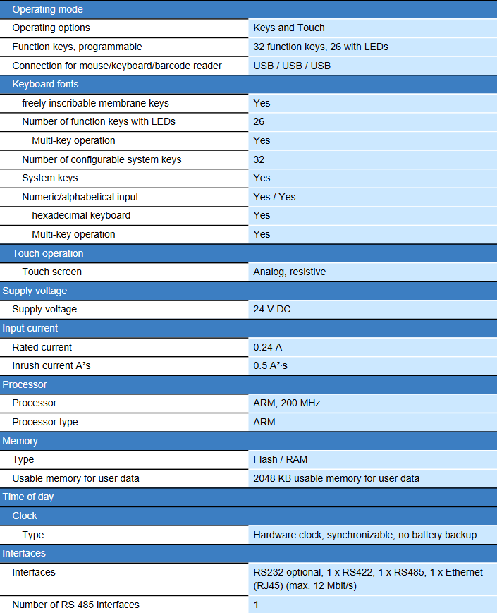
Display screen 5.7-inch STN color screen, resolution 320 × 240 pixels, supports 256 color display; Screen size 120mm × 90mm

The average time between failures (MTBF) of the backlight in a 25 ℃ environment is about 50000 hours, meeting the long-term industrial operation requirements

Dual operation mode: thin film keyboard+analog resistive touch screen, balancing precise input and fast operation

32 programmable function keys (including 26 keys with LED status indicators) are configured for key configuration, supporting numeric/alphabetical/hexadecimal input and multiple key simultaneous operation

Expand input with one USB interface, which can be connected to a mouse, keyboard, or barcode reader to enhance data input flexibility

2. Processor and Storage

Processor: ARM architecture, with a main frequency of 200 MHz, ensuring interface response and data processing speed;

Storage type: Flash flash+RAM memory, available storage space for user data is 2048 KB;

Clock module: hardware clock, supports synchronization function, but does not have battery backup (time needs to be recalibrated after power failure);

Extended storage: Supports MMC/SD card expansion (requires E version 016 and above, and comes with WinCC flexible 2008 SP1 software).

3. Power supply and power consumption

Power supply voltage: 24 V DC (industrial standard DC power supply, compatible with control cabinet power supply);

Rated current: 0.24 A;

Impulse current: 0.5 A ² · s (to avoid impact on the power system when powered on).

4. Protection level and installation

Protection performance: Positive protection level IP65, NEMA 4x/12 (dustproof and splash proof after installation, suitable for humid/dusty environments such as workshops); Back protection level IP20 (to be installed inside the control cabinet to avoid direct exposure);

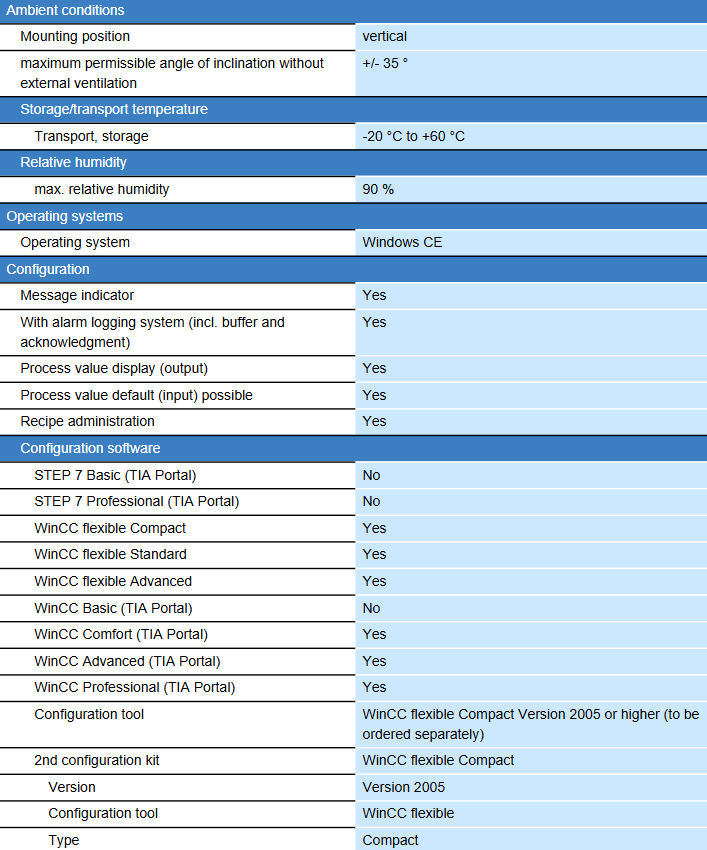
Installation method: Vertical installation, maximum allowable tilt angle ± 35 ° (without external ventilation conditions);

Physical dimensions: Front dimensions 243 mm × 212 mm, weight approximately 1 kg, suitable for standard control cabinet opening installation.

image.png

Communication interface and protocol

1. Interface configuration

Number and specifications of interface types

Industrial Ethernet 1 RJ45 interface, maximum transmission rate of 12 Mbit/s, supports industrial grade network communication, with status indicator light

RS485/RS422 1 RS485 interface+1 RS422 interface, supports serial communication, compatible with traditional industrial equipment (such as frequency converters, instruments)

RS232 optional, expand serial communication capability as needed

USB 1 USB interface, used for external device connection or data transfer

The printer interface supports printer connection and can print documents such as alarm records and shift handover reports

2. Support protocol and controller compatibility

Core protocols: MPI (Multipoint Interface), PROFIBUS-DP (Industrial Fieldbus), PROFINET (Industrial Ethernet) Sm@rtServer agreement;

Compatible controller:

Siemens series: S5, S7-200, S7-300/400, Win AC, SINUMERIK (numerical control system), SIMOTION (motion controller);

Third party brands: Allen Bradley (DF1 protocol), Mitsubishi (FX series), Telemecanique (ADJUST/Uni Always protocol), Modicon (Modbus protocol), etc., compatible with multi vendor automation systems;

Communication function: Supports configuration file upload/download (via MPI/PROFIBUS DP, serial, etc.) USB、 Ethernet or external storage media), supporting automatic transmission recognition.

Software configuration and functionality

1. Software configuration requirements

Siemens specialized HMI configuration software is required, supporting the following versions:

Basic configuration: WinCC flexible Compact 2005 and above versions (need to be ordered separately) WinCC flexible Standard/Advanced;

TIA Portal compatibility: Supports WinCC Comfort/Advanced/Professional (TIA Portal environment), does not support STEP 7 Basic/Professional or WinCC Basic;

Core tool: Implement interface design, variable association, alarm configuration and other functions through WinCC flexible software, supporting project template and library file reuse.

2. Core functions and performance

(1) Monitoring and Display

Screen configuration: Supports up to 500 configurable screens, supports permanent/default windows, customizable startup screen, supports screen switching through PLC control, and screen numbers can be displayed on the screen;

Object elements: Each project supports up to 500 objects, each screen supports 5 dynamic objects (such as trend chart, bar chart, slider, analog display, hidden button), supports 2500 text elements, 30 date/time fields, 500 icons (including 50 full screen icons);

Variable management: A single device supports 1000 variables, each screen supports 50 variables, supports initial and limit value settings, supports variable multiplexing, but does not support structural variables;

Process value display: Supports displaying process values in numerical, textual, and graphical formats (such as bar charts and trend charts), with a maximum of 5 data bars per trend chart and support for displaying limit lines.

(2) Alarm and Log

Alarm management: supports 2000 bit messages and 50 analog messages, up to 32 alarm categories, and supports 99 confirmation groups;

Log function: with alarm buffer and confirmation mechanism, supporting alarm log printing (including color printing and hard copy), supporting shift report generation (handover report);

Message configuration: Each message has a maximum length of 80 characters, supports displaying 8 process values in association, and supports system messages (HMI self status) and PLC messages (controller fault/status).

(3) Formula management

Formula capacity: Supports up to 100 formulas, with each formula containing 200 data records and each data record containing 200 entries;

Storage Expansion: Basic recipe storage of 32 KB (integrated with Flash), expandable storage capacity through MMC/SD card, suitable for multi product production scenarios (such as quick switching of process parameters for different specifications of products).

(4) Security and Permissions

User management: supports 50 user groups, 32 user permission levels, and can assign operational permissions according to roles (such as operators can only monitor, administrators can modify parameters);

Password function: Supports password import/export, records up to 1000 password error attempts, and enhances system security.

Environmental adaptability and certification

1. Environmental parameters

Working temperature: not clearly indicated, refer to storage/transportation temperature (-20 ℃~+60 ℃), suitable for most industrial workshop environments (extreme high/low temperatures should be avoided);

Relative humidity: maximum 90% (non condensing, to avoid circuit faults caused by moisture);

Transportation/storage temperature: -20 ℃~+60 ℃, meeting the needs of logistics transportation and warehouse storage.

2. Compliance certification

This product has passed multiple international industrial certifications and is suitable for applications in multiple regions around the world

Safety certification: CE, UL, CSA, cULus;

Hazardous environment certification: FM Class I Div. 2, EX Zone 2/22 (can be used in non explosion proof areas such as chemical, oil and gas hazardous areas);

Classification certification: GL, ABS, BV, DNV, LRS (some models support, can be used for ship automation systems);

Electromagnetic compatibility: Complies with industrial EMC standards, has strong anti-interference ability, and is suitable for complex electromagnetic environments (such as workshops with dense motors).

Emerson PACSystems RX3i I/O Module

Product positioning and core values

PACSystems RX3i I/O is a modular industrial grade input/output system launched by Emerson, designed specifically for process control, hybrid control, and discrete control scenarios. Its core advantages lie in high-performance data transmission, flexible scalability, and comprehensive diagnostic capabilities, which can adapt to automation needs from small and medium-sized equipment to large and complex production lines. At the same time, it provides a convenient legacy system upgrade path to protect users’ existing investments.

Core Features and Advantages

1. Modular design and high-speed performance

Rich module types: covering digital quantities (voltage, relay output), analog quantities (voltage/current, RTD, thermocouple), and special I/O (high-speed counter, PWM pulse output, strain gauge acquisition, event sequence SoE input), supporting different voltage ranges (such as 24Vdc, 120Vac) and current capacities to meet diverse industrial signal processing needs;

Hot swappable function: All I/O modules support hot swappable, allowing for module replacement without the need to power off, reducing maintenance downtime;

High speed data transmission: Based on high-speed backplane interface, it ensures fast and stable transmission of I/O data, with response speed far exceeding traditional control systems, and is suitable for scenarios with high real-time requirements (such as motion control and precision process adjustment).

2. High scalability and flexible deployment

Customizable scale: A single system supports 8-32000 I/O points, providing various specifications of backplanes such as 7-slot, 12 slot, 16 slot, and 1-slot expansion units, which can be flexibly combined according to application scale;

Multi scenario expansion: Supports local expansion (main backplane overlay expansion backplane) and remote expansion (connected to remote I/O racks through Ethernet or serial bus), with a maximum of 448 I/O points supported by a single drop, suitable for decentralized device layout (such as multi area control in large factory areas);

Media compatibility: support copper cable, SM Fiber, and MM Fiber, and adapt to different transmission distance requirements (such as long-distance communication across buildings in the plant).

3. High availability and redundancy guarantee

Multi level redundancy:

Network redundancy: Supports Media Redundancy Protocol (MRP) and dual LAN architecture to avoid single network link failures;

System redundancy: compatible with PROFINET system redundancy (PNSR) and Ethernet global data (EGD), achieving bumpless switching over between controllers and I/O systems;

I/O redundancy: Key I/O channel redundancy can be configured through application code to further enhance system reliability;

Anti interference and environmental adaptability: Equipped with * * galvanic isolation * * (supporting both digital and analog input and output), strong anti electromagnetic interference capability; The default working temperature is 0-60 ℃, with optional -40~60 ℃ wide temperature version and normal coating (moisture-proof, dust-proof), suitable for harsh industrial environments.

4. Convenient maintenance and compatibility

Easy to connect design: All modules are equipped with pluggable terminal blocks, supporting solid/multi strand wires of 0.081~1.5mm ² (28~14AWG), providing both spring and box terminal types, supporting Terminal Block Quick Connect (TBQC) and forward fixation to ensure stable wiring;

Legacy system upgrade friendly: Series 90-30 modules can be directly reused on the RX3i backplane without rewiring or replacing I/O devices, and the upgrade process only takes a few hours (instead of the traditional solution of days); Simultaneously integrating Ethernet and USB interfaces to replace outdated serial interfaces, enhancing communication flexibility and speed (over 100 times faster than legacy systems).

Detailed explanation of technical specifications

1. Hardware and environmental parameters

Category specific parameters

Installation methods: Panel Mount, Rack Mount

Protection level IP20 (dustproof, preventing fingers from entering)

Working temperature standard: 0-60 ℃; Optional wide temperature range: -40~60 ℃

Isolation performance: All DI/DO/AI/AO channels support galvanic isolation to reduce ground current interference

Terminal specifications: Low density terminals support up to 12AWG wires, while high-density terminals support up to 14AWG wires

Certification standards UL, UL Hazardous Area Certification (Class I Division 2), CE, ATEX Zone 2; Some models support classification certification (ABS, BV, DNV GL)

2. Network and communication capabilities

Core network interfaces: PROFINET, Modbus/TCP, Ethernet Global Data (EGD), Control Memory Switching (CMX), PROFIBUS DP;

Gateway/Bridge Function: Supports serial communication Modbus/RTU、HART、GENIUS、DNP3 Serial/TCP、IEC-61850、IEC-104、 Reflective Memory, CANOpen, etc. can seamlessly integrate with devices from different manufacturers, such as instruments, frequency converters, and third-party PLCs;

Communication port: equipped with 2 RJ45 Ethernet ports and 2 SFP optical ports, supporting flexible switching between fiber and copper cables.

3. Diagnostic and monitoring capabilities

Advanced diagnostic function: The module is equipped with a comprehensive self diagnostic mechanism, which can monitor the terminal wiring status, signal abnormalities (such as overcurrent and over range), module faults in real time, and display alarm information through the controller or upper computer (such as Emerson Proficy software) to quickly locate the problem;

Status visualization: The module LED indicator lights provide clear feedback on power, communication, and channel fault status, making it easy for on-site maintenance personnel to quickly troubleshoot.

I/O module classification and typical models

1. Digital I/O module

Module type, typical model, key parameters

Digital input IC694MDL645 24Vdc, 16 points, positive and negative logic, isolated

IC694MDL240 120Vac, 16:00, non isolated

Digital output IC694MDL730 12/24VDC, 2A, 8 points, positive logic

IC694MDL930 relay output (normally open), 4A, 8 points, isolated

Mixed digital I/O IC694MDR390 24Vdc input (8 points)+relay output (8 points), integrated input-output function

2. Analog I/O module

Module type, typical model, key parameters

Analog input IC695ALG600 universal type, supports voltage/current/RTD/thermocouple, 8-channel non isolated/4-channel differential

IC695ALG306 isolated thermocouple input, 6-channel, compatible with various thermocouple types such as J/K/T

Analog output IC694ALG392 8-channel, supports voltage/current output, non isolated

IC695ALG728 8-channel, voltage/current output, supports HART protocol, can communicate with smart instruments

Mixed analog I/O IC694ALG442 with 4 analog inputs and 2 analog outputs, supporting voltage/current signals

3. Special and Interface Modules

Module type, typical model, key parameters

High speed counter IC695HSC304 1.5MHz, 8 inputs, 7 outputs, supports quadrature encoding, pulse counting, etc

IC694DSM324 multi axis motion controller, compatible with servo/stepper motor control, supports point and trajectory planning

Communication module IC695PNC001 PROFINET controller module, realizing PROFINET network management and device docking

IC695CMM004 4-port serial communication module, supporting RS232/485, compatible with Modbus/RTU and other protocols

Power module IC695PSA040 120/240VAC input, 125Vdc output, 40W, providing stable power supply for the main backplane

IC695PSD140 24Vdc input, 40W multi-purpose power supply, suitable for DC power supply scenarios

Comparison with other Emerson I/O products

The positioning differences between RX3i I/O and other Emerson I/O series can be clearly distinguished through the following table for easy selection:

Product Series Types Core Features Typical Application Scenarios Environmental Adaptability

PACSystems RX3i Chassis Based high performance, high diagnostic capability, support for redundant complex machine control, process control, motion control 0~60 ℃ (optional -40 ℃ wide temperature)

RSTi EP distributed slice miniaturization, decentralized deployment single machine control, lightweight process control -20~60 ℃, IP20

VersaPoint distributed slicing function safety certification (SIL3) safety related controls (such as emergency stop, safety interlock) -20~55 ℃, IP20

RSTi OM on machine distributed (On machine) high protection (IP67), cabinet free installation robots, mobile devices and other non control cabinet scenarios -20~60 ℃, IP67

PAC8000 intrinsic safety explosion-proof certification (ATEX Zone 1) for hazardous environments (such as chemical and oil and gas sites) -40~70 ℃, IP20

Order information and attachments

1. Core component models (some key models)

Component category and model description

Power module IC695PSA040 120/240Vac/125VDC input, 40W, main power supply

IC695PSD140 24Vdc input, 40W multi-purpose power supply

IC694PWR321 120/240Vac/125VDC input, 30W, serial expansion power supply

Backboard IC695CHS007 7-slot universal backplate

IC695CHS016 16 slot universal backplate

IC694CHS392 10 slot serial expansion backplane

Digital input IC694MDL645 24Vdc, 16 points, positive and negative logic, isolated

Digital output IC694MDL730 12/24VDC, 2A, 8 points, positive logic

Analog input IC695ALG600 universal type, 8-channel non isolated/4-channel differential, supports RTD/TC/voltage/current

Analog output IC694ALG392 8-channel, voltage/current output

Note: The meaning of the model suffix is: LT=low temperature version (supported at -40 ℃), CA=normal coating version (moisture-proof/corrosion-resistant), some modules do not support suffix extension.

2. Common attachments

Terminals and labels: IC694ACC311 (20 terminal blocks, 6 pieces/pack), IC694ACC003 (module door label);

Diagnosis and testing: IC694ACC300 (DC voltage input simulator), IC695ACC600 (cold junction compensation kit, compatible with IC695ALG600 module);

Upgrade accessories: IC695ACC651 (Series 90-70 to RX3i I/O adapter card), IC695ACC652 (5-slot conversion rack);

Spare parts: IC695ACC002 (plastic casing for CPU/AC power backup), IC695ACC302 (auxiliary intelligent battery module).

Moxa EDS-508A series network managed Ethernet switch

Initialization configuration: three management interface operations

EDS-508A supports three initial configuration methods: serial port console, Telnet console, and web browser. Please note that the default IP address is 192.168.127.253, subnet mask is 255.255.255.0, and the PC needs to be on the same logical subnet as the switch to access through the network interface.

1. Serial console configuration (preferred when no IP)

Hardware connection: Connect the console port of the switch to the COM port of the PC using an RJ45 to DB9 cable;

Parameter settings: baud rate 115200, no checksum (None), data bit 8, stop bit 1, terminal type VT100 (recommended to use Moxa PComm Terminal Simulator software);

Login process: Select terminal type 1 (ansi/vt100), login account as admin (read-write permission) or user (read-only permission), default no password, can be set as needed (maximum 16 characters).

2. Telnet Console Configuration

Prerequisite: The PC and switch are on the same subnet, and physical connections can be made using either direct or crossover Ethernet cables;

Operation steps: Enter telnet 192.168.127.253 through Windows’ Run ‘, and the subsequent terminal type selection and login process should be consistent with the serial port console;

Attention: Check “VT100 Arrows” in the terminal preference settings to ensure proper cursor navigation.

3. Web browser configuration (easiest to use)

Access method: Enter the switch IP (such as 192.168.127.253) in the browser address bar, and log in with the admin/user account;

Interface features: The left navigation bar categorizes and displays all configuration items, supports visual operations, and is suitable for non professional technicians to quickly get started;

Security advice: If remote management is not required, Telnet and web access can be disabled through the serial port console to reduce security risks.

image.png

Detailed Explanation of Core Function Configuration

1. Basic settings: System and network parameters

(1) System Identification and Security

System information: The switch name (such as “Factory Line 1 Switch”), location, and contact information of the maintenance personnel can be configured. The information will be displayed at the top of the web console and in the alarm email;

Password management: The admin account has full permissions, while the user account only has read-only permissions and supports password modification (requires repeated input confirmation, can clear password and restore default);

IP access control: Use the ‘Accessible IP List’ to restrict access to the switch to only specified IPs or subnets (such as allowing only 192.168.1.0/255.255.255.0 network segments), and allow all IPs to access when not enabled.

(2) Ports and network parameters

Port settings: Configure port enable/disable, transmission rate (auto negotiate or fixed 10M/100M full/half duplex), flow control (FDX Flow Ctrl), MDI/MDIX mode (default auto detect);

Network configuration:

IPv4: supports manual setting of IP, subnet mask, gateway, or automatic acquisition through DHCP/BootP;

IPv6: Supports link local address (automatically generated) and global unicast address (requires prefix configuration);

DNS: Primary and backup DNS servers can be set up, supporting access to switches through domain names (DNS needs to be configured first).

(3) Time management

Time synchronization: Supports NTP/SNTP clients, configurable primary and backup time servers (such as time. nist. gov), with a default query cycle of 600 seconds;

Time zone and daylight saving time: The default GMT time zone allows for manual setting of daylight saving time start/end dates and time offsets;

Attention: Models without real-time clock (such as EDS-508A) require time synchronization after restart. It is recommended to configure NTP server for automatic calibration.

2. Network reliability: redundancy and traffic control

(1) Turbo Ring Redundancy (Industrial Scene Core)

Enabling method: Through the top DIP switch (switch 4) or software configuration, Turbo Ring v2 protocol is supported by default, with recovery time< 20ms@250 Switch;

Attention: If VLAN or port aggregation needs to be enabled on the last 4 ports, Turbo Ring cannot be activated through DIP switches and must be configured through software.

(2) Port Trunking

Function: Bind multiple ports into an aggregation group (up to 4 groups, with a maximum of 8 ports per group), increase bandwidth (e.g. aggregate 8 100BaseTX full duplex ports to achieve a bandwidth of 1.6Gbps), and achieve redundancy;

Mode selection: Supports static aggregation (Moxa private protocol) and LACP (IEEE 802.3ad standard). After configuration, the VLAN, multicast filtering, and other settings of the port will be reset to default;

Applicable models: EDS-508A supports 2 aggregation groups, with different numbers of aggregation groups for different models (e.g. EDS-518A supports 3, EDS-728 supports 4).

(3) Traffic Priority (QoS)

Core mechanism: Based on IEEE 802.1p (Layer 2) and TOS/DiffServ (Layer 3) labels, traffic is divided into four priority queues (high/medium/normal/low);

Queue scheduling: Supports two modes: “Weight Fair (8:4:2:1 weight)” and “Strict”. The default is Weight Fair to avoid low priority traffic from starving;

Industrial adaptation: Supports IEC 61850 QoS and can set GOOSE/SMV/PTP and other power automation protocol messages as high priority to ensure real-time performance.

3. Network isolation: VLAN configuration

(1) VLAN mode and type

Support type:

IEEE 802.1Q VLAN: Label based logical isolation, supporting three port types: Access (single VLAN without labels), Trunk (multi VLAN with labels), and Hybrid (removable egress labels);

Port type VLAN: VLAN is divided based on physical ports, with simple configuration but low flexibility. When enabled, IGMP Snooping will be automatically disabled;

Unaware VLAN: does not check VLAN tags, only transmits all tagged messages transparently, suitable for serial connection in other VLAN networks.

(2) Typical application examples

Scenario: Switch A connects devices A (VLAN5), B/C (VLAN2), D (VLAN3), and E (VLAN4), and is interconnected with switch B through Trunk port 3;

to configure:

Device A port is set to Access, PVID=5;

Set the B/C ports of the device to Trunk, PVID=2, and fixed VLAN (tagged)=3/4;

Set the interconnection port of the switch to Trunk and enable the GVRP protocol to automatically synchronize VLAN information;

Set the corresponding port of switch B to Access, and match PVIDs with VLAN2/3/4/5 to ensure normal cross switch VLAN communication.

4. Multicast filtering: reducing network storms

Core agreement:

IGMP Snooping (IP layer): Supports v1/v2/v3, and only forwards multicast traffic to ports that have joined the group by listening to IGMP report/query messages to avoid flooding;

GMRP (MAC layer): dynamically registers multicast addresses, suitable for devices that do not support IGMP;

Static multicast MAC: Manually add multicast addresses and port bindings, suitable for devices that only support multicast but do not have IGMP/GMRP.

Configuration points: After enabling IGMP Snooping globally, it needs to be enabled separately by VLAN; Support ‘Enhanced Mode’, only forwarding multicast to member ports to reduce redundant traffic.

image.png

5. Bandwidth management and security protection

(1) Bandwidth control

Broadcast storm protection: supports limiting port broadcast/multicast/unknown unicast traffic rates (such as 8M), and can temporarily disable ports when exceeded (default disable for 30 seconds);

Entrance/exit speed limit: Configure the entrance/exit speed according to the port (such as limiting it to 10% of the total bandwidth) to avoid single devices occupying too much bandwidth.

(2) Security protection

User authentication: Supports centralized authentication using TACACS+and Radius, replacing local accounts and suitable for large-scale networking;

Port access control:

Static Port Lock: Bind a specific MAC address to a port and only allow communication with that MAC address;

IEEE 802.1X: Based on the client authentication server (such as Radius) – authenticator (switch) architecture, unauthenticated devices cannot access;

ACL access control list (only supported by layer 3 switches): Filter packets based on IP/MAC address, protocol (TCP/UDP), and port number (such as denying access to 192.168.2.0/24 network segment 192.168.0.1).

6. Alarm and diagnosis: rapid fault location

(1) Auto Warning

Email Alert: Configure SMTP servers (such as enterprise email) and recipient addresses (up to 4), triggering events including switch cold start, port link disconnection, traffic overload, configuration changes, etc;

Relay alarm: supports 2-channel relay output, can be associated with key events such as power failure and Turbo Ring breakage, and trigger external sound and light alarms;

Test verification: After configuration, a test email can be sent to confirm that the alarm channel is normal.

(2) Diagnostic tools

Mirror Port: Copy the inbound/outbound/bidirectional traffic of a specified port (monitored port) to the mirror port, and connect packet capture tools (such as Wireshark) to analyze network issues;

Ping test: initiate Ping requests from the switch (not PC initiated) to detect the connectivity between the switch and the target IP;

LLDP protocol: automatically obtains neighbor device information (such as neighbor IP, port, model), supports MXview software to automatically generate network topology.

(3) Monitoring and Logging

Real time monitoring:

Switch level: View the total traffic of all ports, unicast/multicast/broadcast packet rates;

Port level: View the sending and receiving speed and error packet count of a single port;

SFP monitoring: Check the temperature, voltage, and light emitting and receiving power of the optical module (with an error of ± 3dBm);

Log management: Record events such as cold start, configuration changes, authentication failures, port disconnections, etc. It supports exporting log files or sending them to Syslog servers (up to 3 configured).

EDS Configurator: Batch Management Tool

EDS Configurator is a Windows platform specific GUI tool (available for free download from the Moxa official website) that supports batch operation of multiple switches. Its core functions include:

Device search:

Broadcast search: Discover all switches within the same LAN (no need to know IP);

IP search: specify an IP address to locate a single switch (supporting cross WAN/Internet);

Batch configuration:

Firmware upgrade: Select multiple switches to update firmware uniformly (download. rom file in advance);

IP modification: Batch modify switch IP, subnet mask, gateway, support DHCP enable/disable;

Configuration import and export: Export the configuration of a switch as a text file and import it to other devices of the same model to achieve rapid deployment;

Device unlocking: For password protected switches, enter the admin password to unlock, and subsequent operations do not require repeated input.

SNMP and MIB: Remote Monitoring Integration

SNMP version: Supports v1/v2c (community string authentication, default public read-only, private read-write) and v3 (supports MD5/SHA authentication and data encryption, with the highest security);

Trap settings: Configure primary and backup Trap servers to automatically send Trap information when triggering events such as link disconnection or authentication failure;

MIB support:

Standard MIB: including MIB-II (system, interface, IP, TCP/UDP, etc.), dot1dBridge (spanning tree) qBridgeMIB(VLAN);

Private MIB: Provides Moxa-EDS-508A-MIB.my files, supporting monitoring of device specific parameters such as Turbo Ring status and PoE power.

Precautions and Applicable Scenarios

Model compatibility: Some features are only supported by specific models (such as PoE only for PoE models, ACL only for layer 3 switches), and the device model needs to be confirmed before configuration;

Industrial environment adaptation: Supports wide temperature range (-40~75 ℃, with “- T” model), anti electromagnetic interference (ESD contact 6kV/air 8kV), suitable for harsh environments in industrial sites;

Factory reset: It can be executed through serial port/Telnet/web console. After recovery, the default IP (192.168.127.253) needs to be used to reconnect;

Summary

The Moxa EDS-508A series switches offer rich industrial grade features such as Turbo Ring redundancy QoS、802.1X)、 Multi interface management method and batch configuration tool meet the requirements of industrial scenarios for network stability, security, and maintainability. The manual covers the entire process from initialization to advanced configuration in detail, suitable for network administrators and industrial automation engineers to refer to, helping to quickly deploy and operate industrial Ethernet.

Moxa EDS-408A series industrial Ethernet switch

Product positioning and core values

The EDS-408A series is an 8-port entry-level network managed Ethernet switch designed specifically for industrial scenarios, with high reliability, rich industrial protocol support, and flexible management as its core advantages. It can meet the needs of network redundancy, device interconnection, and monitoring in industrial environments, and is suitable for applications in multiple fields such as intelligent manufacturing, transportation, maritime, and railway.

Core functions and advantages

1. Network redundancy and stability

Fast fault recovery: Supports Turbo Ring and Turbo Chain, with a recovery time of less than 20ms under 250 switching units. It is also compatible with RSTP/STP standard redundancy protocol, avoiding network loops and ensuring fast self-healing after disconnection.

Traffic and bandwidth control: Improve data transmission certainty through QoS (IEEE 802.1p, TOS/DiffServ) and prioritize the protection of critical industrial data; Support bandwidth management to prevent network instability caused by sudden traffic; Equipped with port mirroring function, convenient for online debugging and troubleshooting.

2. Network partitioning and security

VLAN support: Covering port type VLANs, IEEE 802.1Q tag type VLANs, and GVRP protocols, simplifying network planning, achieving logical isolation of different device groups, and improving data security.

Security Management: Supports SNMP v1/v2 c/v3 (network management with different security levels), DHCP Option 82 (IP allocation according to policies), and enables active and efficient network status monitoring through RMON (remote monitoring). Alarm information can be sent via email or relay.

3. Industrial protocols and compatibility

Default enabling protocol: PROFINET or EtherNet/IP (distinguished by model, PN models support PROFINET, EIP models support EtherNet/IP), compatible with Modbus TCP protocol, meeting the interconnection needs of mainstream industrial equipment such as PLCs and sensors.

Supporting documents: Provide EDS files for EtherNet/IP, custom AOI commands, and FactoryTalk ®  View panel; PROFINET’s GSDML files and SIMATIC STEP 7 device icons reduce the difficulty of integration with industrial control systems.

4. Flexible management approach

Supports various local/remote management methods such as web browsers, CLI (Command Line), Telnet/serial console, Windows tools, ABC-01 configuration backup tools, etc;

Compatible with MXstudio visual industrial network management platform, it can intuitively monitor and configure multiple switches, simplifying the management complexity of large-scale networking.

Hardware specifications

1. Ethernet interface (classified by model)

The differences in port configuration between different models are mainly reflected in the quantity and fiber types of 10/100BaseT (X) (RJ45) and 100BaseFX (fiber optic). The core classifications are as follows:

Interface Type Model Example Port Quantity/Specification

10/100BaseT (X) (RJ45) EDS-408A/IIP/PN series 8 (supports automatic negotiation rate, full/half duplex, automatic MDI/MDI-X)

EDS-408A-MM/SS series (MM=multimode, SS=single-mode) 6 pieces

EDS-408A-3M/3S/1M2S/2M1S series 5 pieces

100BaseFX (multimode SC) EDS-408A-MM-SC/2M1S-C 2 (multimode fiber, typical transmission distance 4km, wavelength 1300nm)

EDS-408A-3M-SC 3 pieces

100BaseFX (multi-mode ST) EDS-408A-MM-ST 2 pieces

EDS-408A-3M-ST 3 pieces

100BaseFX (single-mode SC) EDS-408A-SS-SC/1M2S-SC 2 (single-mode fiber, typical transmission distance 40km, wavelength 1310nm)

EDS-408A-3S-SC/3S-SC-48 3 pieces

Note: It is recommended to use attenuators when connecting single-mode optical fibers to avoid damaging equipment due to excessive optical power; The transmission distance must meet the requirements of “link budget (dB)>dispersion loss (dB)+total link loss (dB)”.

2. Power supply and protection

Power supply mode: The entire system supports redundant dual inputs and adapts to different voltage requirements:

Conventional models (such as EDS-408A/EIP/PN): 12/24/48 VDC (operating voltage range 9.6-60 VDC);

Special models (such as EDS-408A-3S-SC-48): ± 24/± 48 VDC (operating voltage range ± 19- ± 60 VDC, non miscible polarity).

Protection function: Supports overcurrent protection and reverse polarity protection; The shell is made of metal material, with an IP30 protection level, dust-proof and suitable for industrial environments.

3. Physical and environmental characteristics

Size and Installation: 53.6 × 135 × 105mm (2.11 × 5.31 × 4.13 inches), supporting DIN rail installation and wall mounting (optional wall mounting kit is required);

Temperature adaptability:

Standard model: -10~60 ° C (32~140 ° F);

Wide temperature model (model with “- T”): -40~75 ° C (-40~167 ° F);

Other environmental parameters: storage temperature -40~85 ° C (-40~185 ° F), relative humidity 5% -95% (no condensation);

Anti interference and reliability:

Anti EMI (Electromagnetic Interference): Complies with CISPR 32, FCC Part 15B Class A;

Anti EMS (electromagnetic sensitivity): ESD contact 6kV/air 8kV, EFT power 2kV/signal 2kV, etc;

MTBF (Mean Time Between Failures): Conventional models have a maximum of 1339439 hours, while some models have a minimum of 989940 hours, in compliance with Telcordia (Bellcore) and GB standards.

Key to Model Classification and Selection

There are a total of 22 sub models in the entire series, with core selection dimensions including port configuration, operating temperature, and industrial protocol. Some mainstream models are shown in the table below:

The model type represents the core differences of the model

Full RJ45 port EDS-408A (standard temperature) with 8 RJ45 ports, no fiber optic ports, suitable for short distance wired interconnection

EDS-408A-T (wide temperature range) as above, suitable for low/high temperature industrial environments

Equipped with multi-mode fiber EDS-408A-MM-SC, 6 RJ45+2 multi-mode SC fibers, with a transmission distance of 4km, suitable for medium to short distance fiber networking

Equipped with single-mode fiber EDS-408A-SS-SC, 6 RJ45+2 single-mode SC fibers, with a transmission distance of 40km, suitable for long-distance (such as cross regional interconnection in the factory area) interconnection

Industrial protocol customization EDS-408A-EIP 8 RJ45, default enabled EtherNet/IP protocol

EDS-408A-PN 8 RJ45, default enabled PROFINET protocol

Hybrid fiber type EDS-408A-1M2S-SC 5 RJ45+1 multimode SC+2 single-mode SC, meeting the needs of medium to short/long-distance fiber

Selection tip: The model with “- T” at the end is for wide temperature version, and with “-48” is for bipolar voltage version. It needs to be selected according to the actual environmental temperature, power supply type, and transmission distance requirements.

Certification and Compliance

Safety certification: EN 60950-1, UL 508, UL 60950-1;

Special scenario authentication:

Hazardous environment: ATEX Class I Division 2 (some models);

Maritime: NK, DNV-GL (some models);

Railway: EN 50121-4;

Traffic control: NEMA TS2;

Environmental testing: Compliant with IEC 60068 series (free fall, impact, vibration).

ABB TK821V020 (3BSC95020R1) battery cable

Product core positioning and basic information

TK821V020 (Product ID: 3BSC95020R1) is a prefabricated cable designed by ABB specifically for the AC 800M controller (hardware version 5.1) of the 800xA control system. Its core function is to provide a stable battery power connection for the AC 800M controller, ensuring the continuity of backup power supply for the controller in case of main power interruption and avoiding the loss of critical data or functional interruption of the control system. Its typical application scenario is control systems in the field of industrial automation that rely on AC 800M controllers (such as production process control in power, chemical, and manufacturing industries), which need to be used in conjunction with supporting battery components to ensure reliable connection of the controller’s backup power supply link.

Core technology and specification parameters

(1) Key physical and electrical characteristics

Specification category specific parameter description

Product type: Prefabricated_Cable Factory pre processed and formed, no need for on-site cutting or crimping, directly compatible with the interface between AC 800M controller and battery components, reducing on-site installation errors and time

The conventional installation distance between the controller and battery components in the control cabinet with a length of 2.0 meters, balancing wiring flexibility and signal stability (avoiding voltage drop caused by excessive length)

Net weight of 0.1 kg, lightweight, easy to control wiring operations inside the cabinet, without increasing the overall load-bearing burden of the equipment

The customs tariff number 8538909999 is classified as “accessories for other electrical equipment”, which complies with the international trade commodity coding standard and facilitates cross-border procurement and customs clearance

(2) Adaptation system and compatibility

Target system: ABB 800xA control system, specifically adapted to the controller model under the hardware path of “Control Systems → 800xA → Controllers → AC 800M Hardware → AC 800M Hardware 5.1”;

Connection feature: Dedicated for the backup power supply link of the “battery controller”, the interface specification fully matches the battery power supply port of the AC 800M controller 5.1 version and the output port of the matching battery components, without the need for additional adapters or adapters.

Environmental and Compliance Characteristics

Specific requirements for compliance categories

The classification of WEEE is not within the scope of WEEE (Waste Electrical and Electronic Equipment Directive). The product nature is “cable accessories” and does not belong to the category of mandatory recycling of electronic and electrical equipment. Waste disposal must comply with local industrial waste management regulations

Environmental adaptability: Industrial control cabinets should be installed in control cabinets that meet the requirements of AC 800M controllers (usually 0-60 ℃ temperature, 5% -95% non condensing humidity) to avoid direct exposure to dust, corrosive gases, or extreme temperature and humidity environments

Procurement and Installation Tips

(1) Procurement and Identification

Product identification: When placing an order, it is necessary to verify both the “Product Model (TK821V020)” and “Product ID (3BSC95020R1)” to avoid confusion with other cable models (such as other prefabricated cables for AC 800M controllers);

Customization attribute: It is a prefabricated standardized product with no additional customization options. The length is fixed at 2.0 meters and needs to be confirmed for compatibility based on the actual installation distance between the controller and battery components in the control cabinet (no additional cutting is required for conventional installation scenarios).

(2) Installation precautions

Compatible hardware version: Only compatible with AC 800M controller 5.1 version hardware. Please confirm the controller hardware version (which can be queried through the controller nameplate or 800xA system configuration tool) to avoid interface mismatch with other versions of hardware;

Installation specifications: As a key component of the backup power supply chain, it is necessary to ensure that the cable joints are fully inserted during installation to avoid power interruption caused by looseness; At the same time, it is necessary to separate the wiring from the main power cable to reduce the impact of electromagnetic interference on the backup power supply link;

Compliance: After installation, it is necessary to verify the functionality of the backup power supply link (such as disconnecting the main power supply and confirming whether the controller has switched to battery power) to ensure compliance with the power supply reliability requirements of industrial control systems.

Summary

The core value of ABB TK821V020 (3BSC95020R1) battery cable lies in “dedicated adaptation+plug and play+reliable power supply”:

Specificity: Accurately match AC 800M controller version 5.1 with matching battery components to avoid interface incompatibility issues with universal cables;

Convenience: Prefabricated design reduces on-site installation workload and lowers the risk of wiring errors;

Reliability: The 2.0-meter length and lightweight design balance practicality and stability, ensuring the long-term reliable operation of the backup power supply link.

Sonnax 6R80L-6R100-ZIP Transmission Valve Body Repair Kit

Core positioning and scope of application of the product

Sonnax 6R80L-6R100-ZIP is a valve body repair kit (ZIP KIT) designed specifically for Ford 6R80 (2015+) and 6R100 automatic transmissions ®), The core function is to replace key components inside the valve body that are prone to wear and aging, such as sleeves, valves, sealing rings, pistons, etc., to solve common faults such as decreased shifting quality, abnormal pressure control, clutch slippage, etc., and restore the normal working performance of the gearbox. Its typical application scenarios include:

Transmission repair shop: for major repairs or targeted fault repairs of 6R80/6R100 transmissions (such as shifting shock, delay, fault code reporting pressure control beyond range);

Automotive aftermarket: used for performance refurbishment of old vehicle transmissions to extend their service life;

Professional modification field: Provide enhanced maintenance and improve reliability for high mileage or high-intensity use (such as towing, off-road) transmissions.

This kit belongs to the classic “Zip Valve” series of Sonnax. Please note that it is only compatible with 6R80 and 6R100 transmissions produced after 2015, and is not compatible with previous models such as 6R80 (2009-2014) and ZF6HP series (Gen1/Gen2). The valve body model must be confirmed through a dedicated identification guide before use.

Core functions and suite composition

(1) Core maintenance function

The kit is designed around the three core fault points of “pressure control”, “shift logic”, and “sealing performance” of the 6R80/6R100 valve body. Typical problems that can be solved include:

Abnormal pressure control: unstable, delayed or impacted shifting pressure caused by wear of the main pressure regulator;

Sealing failure: Oil leakage caused by aging of the sealing ring, leading to insufficient clutch oil supply and slipping;

Piston/spring fatigue: Decreased shifting quality caused by the elastic attenuation of the accumulator piston or spring (such as jerking, gear jumping);

Electromagnetic valve adaptation issues: Electromagnetic valve performance failures and fault codes (such as PCA, SSA soleoid related codes) caused by damaged or misaligned sealing rings of the solenoid valve.

(2) Core components of the kit

The kit is divided into component groups according to the installation order, and all parts are Sonnax original compatible parts. The key components are as follows (sorted by installation steps):

Installation steps, component categories, specific specifications and quantities, functional roles

1 pressure regulator sleeve (diameter. 629 “x length. 645”) to replace the original worn main pressure regulator sleeve and restore pressure control accuracy

2 sets of valve and sleeve combination (including valve and matching sleeve) repair the clearance between the valve core and sleeve of the clutch control pressure regulator to solve pressure leakage

3 Internal end plugs and sealing rings – Internal end plugs: 4 pieces

-O-ring: 11 (including 3 spare) seals the internal oil passage of the valve body to prevent oil from flowing into the chamber. The end plug needs to be installed with a “perforated surface facing outward”

4 large end plugs and sealing rings – Large end plugs: 4 pieces

-Large O-ring seals: 6 (including 2 spare) to seal the external large-sized oil passage interface of the valve body, suitable for installation in the lower half of the valve body

5 small end plugs and sealing rings -6 small end plugs

-Small O-ring seals: 9 (including 3 spare) to seal the small-sized oil passage interface outside the valve body, suitable for installation on the upper part of the valve body

6 accumulator pistons and springs – accumulator pistons: 6

-Matching springs: Replace 6 aging clutch accumulator pistons and springs to improve shift buffering performance and reduce impact

5 specifications of sealing rings for 7 solenoid valves (including spare):

-12 × 2mm: 4 pieces (1 spare)

-13.5 × 2mm: 4 pieces (1 spare)

-11 × 1.5mm: 8 pieces (2 spare)

-15.60 × 1.78mm: 1 piece

-12.95 × 1.69mm: 1 sealing requirement for different types of solenoid valves (such as SSA, SSB, SSE) to prevent oil leakage from the solenoid valve

8 Vacuum Testing Tools – Test Spring: 1 piece

-Test plug: 1 for vacuum testing after valve body repair, to check the sealing of the oil passage and the flexibility of valve action

Note: Some packaging pockets are designed for multiple models and may indicate other application information. Please refer to the “Installation Guide” in the kit for accuracy.

Key technical characteristics and installation requirements

(1) Technical adaptability

Accurate size matching

The kit components strictly follow the original specifications of the Ford 6R80/6R100 valve body, such as a pressure regulator sleeve diameter of. 629 “and length of. 645”, which are perfectly compatible with the original valve (diameter of. 645 “, critical mating surface of. 511”) to avoid pressure control failure caused by dimensional deviations. Special attention should be paid: the pressure regulator valve and sleeve cannot be interchanged across different models. Before installation, the dimensions must be confirmed with a caliper (refer to the table below):

Application model key dimensions (A: length/B: diameter/C: diameter)

6R80 (after 2015)/6R100 A=. 645 “, B=. 629”, C=. 511“

ZF6 Gen1 (including 6R80 2009-2014) A=. 645 “, B=. 629”, C=. 495“

ZF6 Gen2 A=.804″,B=.629″,C=.511″

Material reinforcement design

The core components (such as accumulator piston and seal ring) are made of Sonnax special wear-resistant materials: the piston is made of high-strength engineering plastics, which is oil resistant and anti-aging; The sealing ring is made of nitrile rubber or fluororubber material, suitable for transmission oil (Ford XT-6-QSP/Merck SP), and is not easily hardened or deformed after long-term use.

(2) Key installation requirements

Valve body model identification

Before installation, it is necessary to confirm the compatibility of the valve body through the following 3 steps to avoid misuse:

Casting identification: The casting number for the upper valve body of 6R80 (after 2015) is 9FL3P-7A092-BA/FL3P-7A092-AA, and the lower valve body is FL3P-7A101-AA, without D2 Passage Eliminated;

Electromagnetic valve identification: The electromagnetic valve connector is made of transparent material, and the nozzle color is black/brown (ordinary electromagnetic valve) or gray (SSE electromagnetic valve), and the surface of the electromagnetic valve has flow level markings (1-5);

Pressure regulator identification: The pressure regulator sleeve has a dedicated groove (refer to product figure 4), and the size should be consistent with the specifications of 6R80/6R100 in the table.

Installation specifications

Torque requirements: The connecting bolts between the valve body and the gearbox housing have a torque of 8Nm (71 in lb), the metal oil pan bolts have a torque of 14Nm (10 ft lb), and the output shaft flange nuts have a torque of 60Nm (44 ft lb). A torque wrench is required to ensure accuracy;

Installation of solenoid valve: If the old solenoid valve is reused, it needs to be installed back to its original position (TCM has learned its flow characteristics) and cannot be confused; The new solenoid valve needs to correspond to the “nozzle color position” (e.g. brown nozzle corresponds to SSA/SSC/TCC solenoid valve);

Vacuum testing: After installation, the built-in test spring and end plug of the kit must be used for vacuum testing to check the sealing of the oil passage (qualification standard: stable vacuum degree, no obvious leakage), otherwise it may cause the fault to recur after maintenance.

Postoperative calibration

After the repair is completed, it is necessary to reset the adaptive learning value (KAM) of the transmission. It is recommended to use a Ford specific diagnostic tool to perform this;

Complete 6 cycles of light throttle up and down shifting (after the oil temperature reaches 80 ℃) to allow TCM to relearn shifting parameters and ensure shifting quality;

The transmission fluid needs to be filled with Ford original XT-6-QSP or Mercon SP specifications, with a full filling of 9.5 quarts (9 liters) and maintenance filling of 4.2 quarts (4 liters). The oil level should be checked after the temperature reaches 88 ℃ (190 ℉) and the thermal control valve opens.

Fault diagnosis and additional repair suggestions

(1) Typical faults and kit compatibility

The kit can specifically solve the following faults of 6R80/6R100. If the fault exceeds the scope, additional specialized components need to be purchased:

Additional suggestions on the ability to solve typical fault kits

Shift shock/jerking can be solved (replace accumulator piston, pressure regulator). If the fault still exists, check the clutch clearance (must comply with OE specification 0.2-0.4mm)

Shift delay/no reverse gear can be solved (replace end plugs, sealing rings, repair oil passage leaks). Check the transmission oil pump pressure (must comply with 10Nm pump bolt torque)

The fault code of solenoid valve (such as P0868 low pressure) can be solved by replacing the sealing ring and pressure regulator of the solenoid valve. Use an ohmmeter to check the resistance of the solenoid valve (SSA/SSB=5.5 Ω, SSE=18 Ω)

TCC slip/lock abnormality can be resolved (replace TCC related sealing rings, bypass clutch adjuster). Check the wear of the torque converter and replace it if necessary

(2) Key wear areas and testing

The technical manual accompanying the kit specifies in detail the wear areas of the valve body that need to be inspected in detail. It is recommended to verify through vacuum testing:

Lower valve body: main pressure regulator valve, clutch A/E control regulator valve, solenoid valve pressure regulator valve. If the vacuum degree is insufficient (such as below 50% of the standard value), an additional Sonnax oversize valve kit (such as 95740-46K main pressure valve kit) needs to be purchased;

Upper valve body: accumulator piston (sealing in inverted state needs to be tested), clutch B/D control valve. If the piston sinks more than 0.030 “, the reinforced piston needs to be replaced (the kit includes the basic version, and the high-strength version needs to be ordered separately).

Moxa EDS-308 series industrial Ethernet switch

Product core positioning and application scenarios

The EDS-308 series is an 8-port unmanaged industrial Ethernet switch launched by Moxa, positioned as a low-cost, high reliability network connection solution for industrial scenarios. Its design focuses on the stringent requirements of industrial environments, with features such as wide temperature adaptation, fault alarm, anti-interference, etc. It can achieve Ethernet data transmission for industrial equipment (such as PLC, sensors, frequency converters, cameras), and typical application scenarios include:

Industrial automation: data exchange between equipment in manufacturing production lines and smart factories;

Energy and infrastructure: equipment networking in power substations and petrochemical parks (compatible with Class 1 Div. 2/ATEX Zone 2 hazardous areas);

Transportation and Logistics: Network Connection of Rail Transit Signal Systems and Port Terminal Equipment;

Adverse environmental scenarios: industrial sites with high and low temperatures (-40~75 ℃), high electromagnetic interference, and frequent vibrations.

Product model classification and core differences

EDS-308 series is divided into several sub models according to “port type” and “operating temperature range” to meet different transmission media (copper/optical fiber) and environmental requirements. The core categories are as follows:

Model Category Key Configuration Operating Temperature Applicable Scenarios

Pure copper cable type (EDS-308/308-T) with 8 10/100BaseT (X) RJ45 ports EDS-308: -10~60 ℃; EDS-308-T: Short distance (within 100 meters) equipment connection at -40~75 ℃, such as networking of sensors and PLCs in the workshop

Single multimode fiber type (EDS-308-M-SC/MM-SC/MM-ST series) – M-SC: 7 RJ45+1 multimode SC fiber ports

-MM-SC: 6 RJ45+2 multimode SC fiber ports

-MM-ST: 6 RJ45+2 multimode ST fiber ports standard version: -10~60 ℃; -T suffix version: -40~75 ℃ medium to short distance (4-5 kilometers) fiber optic transmission, such as equipment networking across workshops and factories (multi-mode fiber optic supports 50/125 μ m cables)

Single mode fiber type (EDS-308-S-C/SS-SC series) – S-SC: 7 RJ45+1 single-mode SC fiber ports

-SS-SC: 6 RJ45+2 single-mode SC fiber ports standard version: -10~60 ℃; -T suffix version: -40~75 ℃ long-distance (40 kilometers) fiber optic transmission, such as equipment networking across factory areas and long-distance substations (single-mode fiber supports G.652 standard)

Ultra long single-mode fiber type (EDS-308-SC-80/SS-SC-80) – S-SC-80: 7 RJ45+1 single-mode SC fiber ports (80 kilometers)

-SS-SC-80: 6 RJ45+2 single-mode SC fiber ports (80 kilometers) -10~60 ℃ ultra long distance (80 kilometers) transmission, such as networking in large-scale scenarios such as oil fields and wind farms (using 1550nm wavelength, low dispersion)

Core technical specifications and performance advantages

(1) Hardware and port characteristics

Category specific parameters, technical advantages

Port configuration: 10/100BaseT (X) RJ45 ports: 6-8 (depending on model); 100BaseFX fiber ports: 1-2 (depending on model) support automatic negotiation (rate/duplex mode), automatic MDI/MDI-X (no need for crossover), compatible with devices of different rates (10Mbps/100Mbps)

Fiber optic transmission parameters – multimode (MM): wavelength 1300nm, transmission distance 4-5 kilometers, supports OM1/50/125 μ m cables

-Single mode (SM): wavelength 1310nm (40 kilometers)/1550nm (80 kilometers), supports G.652 cable coverage for medium to long distance transmission needs, and fiber optic ports have dust caps to reduce dust impact

Switching performance – MAC address table: 2048 entries

-Package buffer: 768KB

-Forwarding method: Store and Forward to avoid residual frame forwarding, reduce network congestion, and support simultaneous networking of multiple devices (2048 device address records)

Power Characteristics – Input Voltage: 9.6~60V DC (Redundant Dual Input)

-Current: 0.07~ 0.15A@24V DC (by model)

-Protection: Reverse polarity protection, overcurrent protection, wide voltage input suitable for unstable power supply in industrial sites, dual redundant input+fault protection to enhance power supply reliability

(2) Industrial grade reliability design

environmental adaptability

Temperature: Standard version -10~60 ℃, wide temperature version (- T suffix) -40~75 ℃, suitable for high and low temperature industrial scenarios (such as outdoor in winter in the north and workshop in summer in the south);

Humidity: 5%~95% (no condensation), suitable for humid environments (such as food processing and water treatment workshops);

Protection level: IP30 (metal shell), dustproof and finger proof, suitable for installation inside control cabinets;

anti-interference:

Electrostatic discharge (ESD): Contact with 6kV, air 8kV (IEC 61000-4-2);

Radio frequency interference (RS): 80MHz~1GHz, 20V/m (IEC 61000-4-3);

Surge: 2kV at the power supply end and 2kV at the signal end (IEC 61000-4-5).

Fault alarm and protection

Relay alarm: 1 relay output( 1A@24VDC ), can trigger “power failure” and “port disconnection” alarms, and promptly notify operation and maintenance personnel;

Broadcast storm protection: Suppress network broadcast storms and prevent single device failures from causing the entire network to crash;

100% aging test: Full process aging test before leaving the factory to ensure long-term stable operation in industrial scenarios.

Compatible with hazardous areas

Certification: ATEX Zone 2, Class 1 Div. 2, can be used in flammable and explosive environments such as petrochemicals and gas processing to reduce safety risks.

Installation and Accessories

(1) Installation method

DIN rail installation: standard DIN rail buckle, compatible with 35mm standard rail, easy to install densely inside the control cabinet;

Wall mounted installation: Optional wall mounted kit (WK-46) is required, including 2 mounting plates and 8 screws, suitable for scenarios without rails;

Size and weight: 53.6 × 135 × 105mm (width × length × height), weight 790g, compact size, saves installation space.

(2) Recommended accessories

Accessory type, model, specification, and purpose

Power adapter DR-120-24 120W/2.5A, input 88~132VAC/176~264VAC/248~370VDC to provide stable 24VDC power for the switch, compatible with a wide range of input voltages

DR-75-24 75W/3.2A, Input 85~264VAC/120~370VDC medium power supply, suitable for single switch power supply

MDR-60-24 60W/2.5A, Input 85~264VAC/120~370VDC, -20~70 ℃ wide temperature power supply, suitable for harsh temperature environments

Installation kit WK-46 includes 2 mounting plates and 8 screws (46.5 × 66.8 × 1mm) for wall mounted installation of switches, suitable for scenarios without DIN rails

Compliance certification and quality assurance

(1) Core certification

Safety certifications: UL 508 (Industrial Control Equipment), UL 60950-1, CSA C22.2 No. 60950-1 (Information Technology Equipment Safety);

Electromagnetic compatibility (EMC): CISPR 32, FCC Part 15B Class A, EN 55032/24;

Environmental certification: ATEX Zone 2, Class 1 Div. 2 (hazardous areas), IEC 60068 (environmental testing).

(2) Warranty and Reliability

Warranty period: 5-year ultra long warranty, covering the repair of core product faults;

Mean Time Between Failures (MTBF): 255528 hours (according to MIL-HDBK-217F standard), approximately 29 years, with high long-term operational reliability.

ABB Symphony Plus S+Control BRC410 Controller

Product core positioning and brand background

BRC410 is the core controller module in ABB’s Symphony Plus distributed control system (DCS), positioned as an integrated solution of “high-performance control+multi device integration”. It inherits the reliability and compatibility of ABB’s classic Symphony series DCS, while integrating new generation hardware and communication technologies. Its core goal is to provide high-precision process control, flexible equipment integration, and seamless system upgrade capabilities for key industries such as power and water, ensuring the continuity, efficiency, and scalability of industrial production.

The Symphony series DCS has a history of over 30 years of application, with over 6000 installations worldwide, of which 4000+are used in the fields of power and water. BRC410, as the new generation controller of this series, continues ABB’s core policy of “Desarrollo sin caer en desuso”, ensuring compatibility with the hardware architecture and software functions of previous products such as BRC400, HPG800, Network 90, INFI 90, and protecting users’ existing asset investments.

Core functions and technological advantages

(1) High performance process control capability

BRC410 takes “high precision, high response, and high flexibility” as its control core, meeting the requirements of continuous, sequential, batch, and advanced control. The key characteristics are as follows:

Technical parameters, specific specifications, functional advantages

Hardware foundation: 32-bit Freescale Coldfire processor with a main frequency of 160 MHz, fast computing speed, and a performance improvement of 10 times compared to previous generation controllers. It can quickly handle complex control algorithms

The control algorithm library has 150+predefined function blocks (such as PID, logic control, batch control blocks) built-in, supporting C language programming and batch control without the need for zero development. It can quickly build complex control strategies (such as turbine control in the power industry and water treatment process control in the water industry)

The control scale supports 30000 functional blocks and can achieve closed-loop control of 2000 I/O points (cycle period<250 ms) to meet the centralized control requirements of multiple devices in medium and large industrial scenarios (such as large thermal power plants and urban sewage treatment plants)

Reliability design supports redundant configuration (forming a redundant pair with BRC400/HPG800), firmware is downloadable, 2 MB NVRAM user configured memory redundancy design reduces the risk of single point of failure, NVRAM ensures that configuration data is not lost after power failure, firmware online updates do not interrupt operation

(2) Fully compatible I/O control capability

BRC410 achieves seamless integration with ABB’s full range of I/O subsystems, covering local and remote I/O requirements, while providing industry-specific control modules, including:

I/O compatibility and expansion

Local I/O: Up to 64 Harmony rack mounted I/O modules can be connected, supporting signal types such as digital (DI/DO), analog (AI/AO), and sequence of events (SOE). The SOE module has a timestamp resolution of milliseconds, meeting the high-precision time recording requirements for fault tracing;

Remote I/O: Expand remote rack mounted I/O through RIO22 module, and be compatible with S800 I/O system (DIN rail modular design, compact size, can be installed near on-site sensors), reducing signal transmission loss and wiring costs;

Specialized control module: For the steam turbine control scenario in the power industry, customized rack mounted modules are provided, including hydraulic servo module (HSS), steam turbine protection module (TPS), automatic synchronization module (TAS), and status monitoring module (CMM), achieving the integration of “control+protection+monitoring”.

I/O configuration tool

Through S+Engineering Composer software, all I/O modules and channels can be uniformly configured, supporting flexible online configuration adjustment. Signal type, range and other parameters can be modified without stopping the machine, adapting to dynamic changes in the production process.

(3) Multi device integration and communication capability

BRC410 breaks through the limitations of traditional controllers’ “single control” and achieves real-time bidirectional integration of multiple protocols and devices through Harmony Gateway Software (HGS). The core communication characteristics are as follows:

Specific specifications and application value of communication parameters

Core interface 100 MB Ethernet port, supports Modbus TCP protocol instead of traditional RS232/RS485 serial port, achieves high-speed data transmission, compatible with industrial standard Ethernet devices (such as switches, fiber routers)

The integration scale supports up to 4000 Modbus points for bidirectional communication, and can be used as a Modbus TCP client, server, or both to flexibly interface with third-party devices

-As a ‘client’: collecting data from intelligent electronic devices (IEDs, such as meters and sensors);

-As a ‘server’: pushing control data to third-party PLCs (such as AC 800M, AC 500) or SCADA systems;

-Bidirectional mode: enables real-time data exchange and control command issuance with wireless HART transmitters

Redundancy and Reliability Redundancy supports communication link fault tolerance under configuration, and is paired with industrial grade Ethernet devices (such as fiber optic switches) to achieve long-distance (fiber optic link) and high reliability communication. It is suitable for cross plant and strong interference scenarios (such as power plant boiler areas and water pump stations), ensuring uninterrupted communication

Seamless system upgrade and compatibility

BRC410 is the core carrier of ABB’s “development without elimination” policy, and its compatibility and upgrade capabilities are designed to fully protect users’ existing investments, specifically reflected in:

Hardware and functional compatibility

Consistent in size and functional interoperability with previous generation controllers (BRC400, HPG800), one module can be directly replaced as a redundant backup without the need to modify cabinet layout or wiring;

Compatible with user-defined programs and functional block execution logic of old systems such as Network 90 and INFI 90, it can be migrated to BRC410 without rewriting code.

Online upgrade capability

When BRC410 is used as a redundant backup module for BRC400 or HPG800, it can gradually upgrade controller functions (such as upgrading from “basic control” to “Modbus TCP integration”) or gateway capabilities without interrupting existing production applications, achieving “zero downtime upgrade”;

Supports the coexistence of traditional RS232/RS485 serial port interfaces and new generation Ethernet interfaces. Users can transition to high-speed Ethernet communication in stages according to their needs, avoiding one-time system replacement costs.

Typical application scenarios

BRC410, with its characteristics of “high reliability, strong compatibility, and multi scenario adaptation”, is core applied in the following fields:

Power industry: Unit control of thermal power plants and hydropower plants (such as boiler water level control, turbine speed regulation), control of auxiliary systems (pumps, fans), and exchange of power grid dispatch data;

Water industry: urban waterworks (dosing, filtration process control), sewage treatment plants (aeration, sedimentation process control), supporting data integration with remote pumping station’s IED equipment;

Other key industries: continuous production process control in chemical, metallurgical and other fields, compatible with third-party equipment (such as flow meters, valve positioners), achieving full process automation.

GE Qualitrol IC670ALG230 Analog Input Module

Product core positioning and application scenarios

IC670ALG230 is a current source analog input module launched by Qualitrol (now under GE). Its core function is to accurately convert the current signals (0-20 mA or 4-20 mA) output by 2-wire, 3-wire, or 4-wire sensors/transmitters in industrial fields into digital signals, which are transmitted to the GE field control system (with a bus interface unit BIU) to achieve real-time acquisition and monitoring of process parameters such as pressure, temperature, and flow rate. Its typical application scenarios cover industrial fields such as power, petrochemicals, and manufacturing, and are suitable for automation systems that require high accuracy of analog signals and centralized collection of multi-channel current signals.

Core technical specifications

(1) Basic parameters of module

Category specific specification description

Channel configuration with 8 single ended grouped inputs (shared signal ground) and 8 inputs sharing the same 24 VDC power supply and signal common terminal, suitable for centralized collection of signals from similar sensors

Software configurable input signal range: 0-20 mA (default), 4-20 mA supports industrial standard current signals, 4-20 mA mode can detect wire breakage faults (input<2.0 mA triggers diagnosis)

Power supply requirement: Power supply voltage: 18-30 VDC (typical 24 VDC); Module power consumption: 50 mA (module only), 210 mA (including loop current) can share 24 VDC power supply with bus interface unit (BIU), please note that the total current load does not exceed the limit value

Isolation performance for ground and logic isolation: 1500 VAC (1-minute withstand), 250 VAC (continuous withstand), high isolation level to suppress industrial field grounding loops and electromagnetic interference (EMI), protect modules and backend systems

(2) Signal Conversion and Accuracy

Category specific specifications Technical advantages

Resolution: Digital resolution of 12 bits, analog resolution of 5.0 μ A, high-precision conversion ensures that small current changes can be recognized (such as a minimum resolution of 4 μ A changes under 4-20 mA signals)

Conversion speed of approximately 60 μ s per channel (1 MHz clock). Fast conversion supports high-frequency data acquisition and is suitable for dynamic process monitoring (such as rapidly changing pressure signals)

Measurement accuracy at 25 ℃ ± 0.05% full range (0.1-20 mA input), non-linear error ± 0.025% full range high precision meets industrial level process control requirements, reducing the impact of signal acquisition errors on control logic

Typical temperature coefficient is ± 0.002%/℃, with a maximum of ± 0.005%/℃. Within a wide temperature range (commonly seen in industrial sites -10-60 ℃), the accuracy attenuation is small, making it suitable for complex environments

(3) Input protection and anti-interference

Overcurrent protection: maximum input current of 30 mA, built-in 1 A fuse (24V output circuit) to prevent overcurrent damage caused by sensor failure;

Overvoltage protection: 30 V MOV (metal oxide varistor) to suppress voltage spikes on the power supply side;

Filter design: A first-order RC filter with 250 Ω resistor and 0.1 μ F capacitor connected in series for each channel, with a transition frequency of approximately 160 Hz, to filter out high-frequency noise;

Wire breakage detection: Only 4-20 mA mode is supported. When the input current is less than 2.0 mA, the BIU triggers wire breakage diagnosis for timely troubleshooting of sensor faults.

Hardware Design and Working Principle

(1) Internal circuit structure

The core circuit of the module revolves around “current voltage conversion+signal conditioning+A/D conversion”, and the key path is as follows:

Signal input: After the current signal of the on-site sensor is connected to the channel, it first passes through a 250 Ω precision resistor to convert the current signal into a voltage signal (such as 20 mA corresponding to 5 V voltage);

Filtering and buffering: After the RC filter filters out high-frequency noise, the signal is buffered by an operational amplifier (OPAMP) to avoid load effects affecting measurement accuracy;

A/D conversion: A 12 bit A/D converter converts analog voltage into digital signal, and the conversion result is temporarily stored in an 8-word (16 byte) data buffer inside the module;

Data transmission: Unscaled digital data is transmitted to the host or local processor through a bus interface unit (BIU), and the BIU performs engineering unit scaling (such as mapping 4-20 mA to 0-100 ℃).

(2) Status indication and wiring

LED indicator light: The transparent area at the top of the module is equipped with an LED, which lights up under the conditions of “backplane power supply+normal on-site power supply+fuse not blown” to visually determine the power supply status of the module;

Terminal layout: Using standardized I/O terminal blocks (supporting box type terminals IC670CHS002/102, fence type terminals IC670CHS001/101, and wire to board connectors IC670CHS003/103), the key terminals include:

+24 V Out “: 8 channels of shared 24 V output (with fuses), providing loop power for 2-wire transmitters;

Input 1-8 “: 8-channel current signal input terminal;

DC – “/” Common “: The signal common terminal needs to be connected to the sensor signal ground to avoid grounding loops;

Chassis Ground “: The module casing ground needs to be short circuited to the control cabinet casing to enhance anti-interference capability.

On site wiring and sensor adaptation

The module supports 2-wire, 3-wire, and 4-wire sensors/transmitters, and the wiring method needs to be selected according to the sensor type. The key configurations are as follows:

(1) 2-wire transmitter (loop power supply)

Wiring characteristics: The sensor power supply and signal share two wires. The module “+24 V Out” provides circuit power, “Input” receives current signals, and “DC -” is the common terminal;

Attention: AWG # 14- # 22 (cross-sectional area 0.36-2.1 mm ²) should be used as the wire, and the recommended maximum wiring distance should not exceed 100 meters (to avoid voltage drop causing insufficient sensor power supply); The shielding layer needs to be grounded separately and not shared with the power supply ground.

(2) 3-wire transmitter (independent power supply+signal)

Wiring characteristics: The sensor requires separate power supply (module “+24 V Out” or external power supply can be used), the signal terminal “+” is connected to module “Input”, “-” is connected to “DC -“, and the power supply “-” and signal “-” are grounded together;

Adaptation scenario: For sensors that require higher power supply voltage or current (such as some high-precision temperature transmitters), it is recommended to use an auxiliary terminal block to consolidate the common terminal and simplify wiring.

(3) 4-wire transmitter (completely isolated)

Wiring characteristics: The sensor power supply is completely isolated from the signal (independent external power supply), the signal “+” is connected to “Input”, “-” is connected to “DC -“, and the power ground and signal ground are separated to avoid ground loop interference;

Advantages: Suitable for long-distance (such as over 200 meters) or strong interference scenarios (such as near frequency converters), isolation design improves signal stability.

(4) Wiring specifications

Wire selection: It is recommended to use shielded twisted pair for analog signals, with the shielding layer grounded at one end (preferably on the module side);

Grounding requirements: Only ground the signal common terminal on the module side to avoid multiple grounding points forming a ground loop; The module ‘Chassis Ground’ needs to be connected to the control cabinet casing with a short wire (recommended<4 inches, # 14 wire);

Auxiliary terminal block: When using fence type terminals or wire to board connectors, auxiliary terminal blocks (such as IC670CHS series) should be used to expand the wiring terminals. All terminals inside the auxiliary terminal block are connected and can be used to summarize the common terminal or power terminal.

Software Configuration and Data Processing

(1) Parameter configuration

The module needs to be parameterized through a Bus Interface Unit (BIU) or host software, with the following key configuration items:

Input range: Each channel is independently configured with 0-20 mA or 4-20 mA, with a default range of 0-20 mA;

Engineering unit scaling: defined by BIU as “Engineering Lower Limit (Eng Lo) – Engineering Upper Limit (Eng Hi)” and “Integer Lower Limit (Int Lo) – Integer Upper Limit (Int Hi)”, default scaling is Eng Lo=0, Eng Hi=20000 (corresponding to 0-20 mA), Int Lo=0, Int Hi=20000;

Diagnostic enablement: Enable disconnection diagnosis (triggered by input<2.0 mA) and over range diagnosis (triggered by input>20.5 mA) in 4-20 mA mode.

(2) Data transmission

Data format: 8 inputs correspond to 8 16 bit digital quantities (unsigned integers), stored in the module data buffer, and periodically read by BIU (read cycle depends on system configuration, typically 10-100 ms);

Scaling logic: Taking the mapping of 4-20 mA to 0-100 ℃ as an example, BIU calculates the engineering value according to the following formula:

Engineering value=Eng Lo+Int Hi − Int Lo

Digital quantity – Int Lo × (Eng Hi – Eng Lo) (Example: When the digital quantity is 8000, the corresponding current is 8 mA, and the engineering value is 25 ℃).

ABB DCS series thyristor power converter

Product core positioning and application scenarios

The ABB DCS series thyristor power converter is an industrial grade power conversion equipment designed specifically for DC drive systems. Its core function is to accurately convert three-phase AC power into adjustable DC power, providing stable armature and excitation power for DC motors. At the same time, it integrates complete control, protection, and communication functions to achieve precise control of motor speed and torque. Its typical applications cover medium and high voltage industrial scenarios, including:

General industrial drive: medium and high-power DC motor control in metallurgy (rolling mill), mining (hoist), papermaking (coiler), chemical (pump/fan) and other fields;

Special scenario adaptation: Supports MultiDrive, CraneDrive, 12 pulse series/parallel topology, which can meet high power (up to 5200A output current, power above 10MW) and high reliability requirements;

Upgrade and Renovation: Compatible with old DC drive systems, providing modular design for easy upgrading of existing equipment and reducing renovation costs.

Product series and core categories

The DCS series is divided into multiple sub models based on power level and functional complexity, covering different application requirements. The core classifications are as follows:

Product Model Power/Current Range Core Features Applicable Scenarios

DCS 400 10-500 kW (corresponding to motor power), integrated excitation output (up to 20A), compact design, built-in IGBT excitation module, supports quick debugging (guided configuration+application macro), compact structure for standard industrial scenarios (such as small pumps and fans), equipment with high installation space requirements

DCS 500B 10-5000 kW, Output current 25-5200A based on SDCS-CON-2 control board, supports 300+programmable function blocks, compatible with HART signals, optional 12 pulse configuration for high-power universal drives (such as compressors and rolling mill auxiliary drives), suitable for scenarios requiring flexible programming

DCS 600 10-5000 kW, Upgrade SDCS-AMC-DC control communication board with an output current of 25-5200A, supporting DDCS bus (4Mbps) and PROFIBUS-DPV1, suitable for high demand industrial scenarios with multiple drives and PLC integration (such as cranes and large fans), requiring multi device collaborative control systems

DCF 500B/600 excitation dedicated, maximum output current 520A based on DCS 500B/600 hardware, supports three-phase excitation mode, requires DCF505/506 overvoltage protection unit for DC motor excitation power supply, suitable for large synchronous motors and DC motor excitation control

DCA/DCE series 10-18000 kW (DCA 600) integrated complete control cabinet (including circuit breakers, contactors, auxiliary transformers), pre programmed industry applications (metallurgy, mining) complex system solutions (such as whole production line transmission, large mining equipment)

Core hardware and technical specifications

(1) Power module and electrical parameters

The DCS series power modules are divided into C1/C2/A5/A6/A7 sizes according to current levels, covering different output current requirements. The core parameters are as follows:

Module size, output current range, voltage level, cooling method, key configuration

C1 25-140A 400-1000V DC forced air cooling (with built-in fan) single/double bridge thyristor topology, supporting 2-quadrant (2-Q)/4-quadrant (4-Q) operation

C2 200-1000A 400-1000V DC forced air cooling with multiple parallel thyristors, supporting 12 pulse series connection, suitable for medium power motors

A5 900-2000A 400-1000V DC forced air/water cooling (optional) modular thyristor group, supporting galvanic isolation, suitable for high-voltage motors

A6/A7 2050-5200A 400-1000V DC water-cooled (standard) multi bridge parallel connection, supports redundant design, suitable for high-power scenarios (such as motors above 10MW)

Key electrical performance

Current accuracy: ± 0.5% full range (at rated current), current imbalance compensation range of 4% -30%;

Voltage range: Input AC 400-690V (50/60Hz), output DC 0-1000V (depending on the model);

Power loss: including current dependent loss (thyristor, fuse), voltage dependent loss (buffer circuit), fixed loss (electronic components, fan), typical value 10-17250W (depending on current level);

Overvoltage/over-current protection: Built in MOV (metal oxide varistor), RC buffer circuit, over-current trip time can be set (10ms-2000ms), ground fault detection supports 50:0.025A/1A/5A CT.

(2) Control and Interface Module

The DCS series core control relies on dedicated circuit boards to achieve signal acquisition, logic control, and communication interaction. The key modules are as follows:

Module Name Core Function Technical Features

SDCS-CON-2 (control board) core logic control, including 80186EM processor, ASIC circuit supporting RS485 (2 channels, used for excitation control and panel communication), DDCS bus (4Mbps), built-in watchdog, monitoring 6 voltage channels (+5V/+15V/-15V/+24V/+48V1/+48V2)

SDCS-POW-1 (power board) provides multi-level DC voltage (+5V/+15V/-15V/+24V/+48V) switch power supply design, input AC 115/230V (± 10%), power consumption 120VA, supports encoder power selection (5V/12V/24V)

SDCS-PIN series (power interface board) thyristor triggering, current/voltage measurement, hardware coding PIN-1x (C1 module), PIN-20x (C2 module), PIN-41/51 (A5/A6/A7 module), supports current transformer signal acquisition, zero current detection

SDCS-IOB series (I/O board) expands digital/analog I/O IOB-2 (8-channel isolated digital I/O), IOB-3 (5-channel analog input+3-channel analog output, supports encoder isolated input), compatible with PT100/PTC temperature sensors

SDCS-COM-5/AMC-DC (communication board) external communication extension COM-5 supports HDLC (1.5Mbps) and DDCS (4Mbps); AMC-DC supports PROFIBUS-DPV1, fiber optic communication (10Mbps), and is compatible with multi drive collaboration

Core functions and technological advantages

(1) Precise control and adjustment

Excitation control:

Built in excitation module (SDCS-FEX-1/2, output 6-16A) or external excitation unit (DCF503A/504A, output 50A), supports separate/parallel excitation motors, and is compatible with weak magnetic speed regulation;

Excitation current closed-loop control, with an accuracy of ± 1%, supports excitation fault detection (such as demagnetization protection), and is equipped with DCF505/506 overvoltage protection to prevent excitation winding overvoltage damage.

Speed and torque control:

Support PID speed regulation (proportional gain, programmable integration time), speed accuracy ± 0.1% (with encoder feedback);

Torque and current limiting functions to prevent motor overload and adapt to load fluctuation scenarios (such as crane lifting).

Multi quadrant operation:

The 4-quadrant module (such as DCS 500B-4Q) supports motor forward and reverse rotation, power generation braking, and is suitable for scenarios that require energy feedback (such as elevators, lowering loads).

(2) Comprehensive protection mechanism

Protection type, specific functions, technical details

Thermal overload protection is based on dynamic calculation of motor thermal capacity (TCU), considering negative sequence current bias (additional rotor heating) and RTD temperature bias (stator/bearing temperature correction), supporting 15 standard overload curves and custom FlexCurve ™

Electrical fault protection short circuit, grounding, undervoltage/overvoltage, phase sequence reversal short circuit tripping time 10ms-2000ms, grounding fault detection sensitivity 0.25-25A, phase sequence reversal protection response time ≤ 100ms

Mechanical fault protection for locked rotor, bearing high temperature, and anti rotation detection. The locked rotor protection is based on current threshold (2-10 × FLC), RTD monitors bearing temperature (-40-200 ℃), and anti rotation detection (option B) is suitable for underground pumps to prevent damage caused by reverse restart

Disable thyristor triggering when the system protection watchdog, power monitoring, and EMC protection watchdog are triggered; Power undervoltage (such as+5V below 4.55V) triggers hardware reset; Supports EN 61000-6-2/4 EMC standard, optional NF3/NF1 series EMC filters

(3) Data Collection and Communication

Status monitoring:

Real time collection of parameters such as current, voltage, power, temperature (RTD), speed, etc., with an accuracy of ± 1% – ± 2%;

Event records (512 records, including reasons for tripping, current/voltage waveforms), startup data recorder (recording 30 second startup process), supporting fault tracing.

Communication ability:

Supports Modbus RTU/TCP, PROFIBUS-DPV1, DeviceNet, DDCS fiber optic bus, and can be connected to PLC (such as ABB AC800M) and SCADA systems;

Multi drive communication (DDCS bus, 4Mbps) supports master-slave control (such as multi motor synchronization), and fiber optic communication distance can reach 200 meters (HCS fiber optic cable).

Installation and Accessories

(1) Installation configuration

Module installation: C1/C2 modules are installed using DIN rails or 19 inch racks, while A5/A6/A7 modules require independent cabinet installation (supporting water-cooled pipe connections);

Wiring requirements: Power cables (copper bars/cables) with a cross-sectional area of 2.5-100mm ² (depending on current level), control cables need to be shielded (EMI resistant), encoder cables support differential signals (up to 150 meters long);

Environmental adaptation: Working temperature 0-50 ℃ (air-cooled), 0-40 ℃ (water-cooled), relative humidity 95% (non condensing), protection level IP20 (module)/IP54 (control cabinet).

(2) Key accessories

Accessory type, model/specification, and purpose

EMC filters NF3 series (three-phase, 25-2500A) and NF1 series (single-phase, 8-55A) suppress conducted interference, meet the EN 50081 standard, and are suitable for public grid access

The ND series of incoming reactors (ND01-ND16, inductance 50-512 μ H) reduces grid harmonics, improves power factor (cos π≥ 0.9), and protects thyristors

Residual current detection for current transformers PWS 10004 (1500A) and PWS 33001 (3300A), compatible with ground fault protection

Cooling accessories fan (CN52B2, W2E143), water-cooled radiator to ensure module heat dissipation, A7 module water-cooled flow rate ≥ 5L/min (Δ T ≤ 30 ℃)

Programming tool DriveWindow software, CDP312 panel parameter configuration, fault diagnosis, real-time monitoring, supports offline programming and online debugging

Model selection and ordering information

(1) Model coding rules

Taking “DCS 500B-0250-51-4Q” as an example, the key parameter meanings are:

500B “: Basic model;

0250 “: Output current 250A;

51 “: Voltage level 500V DC;

4Q “: Running in 4 quadrants.

(2) Core selection criteria

Motor parameters: Select the module based on the rated power of the DC motor, armature voltage/current, and excitation voltage/current (e.g. 100kW/440V motor compatible with DCS 500B-0250-51);

Application requirements: Select 4-quadrant module for energy feedback, DCS 600+AMC-DC communication board for multi motor synchronization, and water-cooled module for high temperature environment;

Power grid conditions: The public power grid needs to be equipped with EMC filters, and if the power grid harmonics are severe, line reactors need to be added.

Search for products

Back to Top
Product has been added to your cart