Call us 24/7uaedcs@163.com
Welcome to the official website of CNIACS Automation Technology Co., Ltd!
Call us 24/7uaedcs@163.com

Triconex 3624 Digital Output Module

Overview of the Core of Tricon Fault Tolerant Control System

Core Definition and Architecture

Fault Tolerant Control: capable of identifying and compensating for faulty control units, allowing for repairs without interrupting processes, suitable for critical process applications that require high safety and availability.

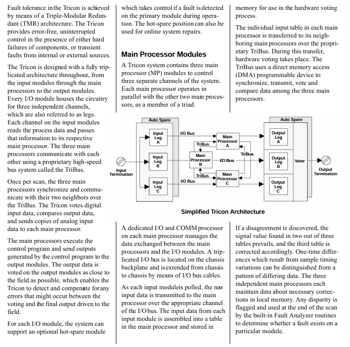
Tricon controller: It adopts the third mock examination redundancy (TMR) architecture to achieve fault tolerance, integrates three independent parallel control systems and comprehensive diagnostic functions, ensures no single point of failure through the “three out of two” voting mechanism, and achieves high integrity, error free, and uninterrupted process operation.

TMR architecture details: Three identical channels independently and parallelly execute control programs, digital I/O is verified through dedicated software and hardware voting, and analog input adopts median selection; The channels are isolated from each other, and a single channel failure does not affect other channels. The faulty module can be replaced online.

Key Features

No single point of failure; Support 3, 2, or 1 main processor to run until shutdown; Fully implemented and transparent triple transformation; Comprehensive system diagnosis; Complete I/O module series; Provide dual I/O and single I/O modules for safety critical and limited availability requirements; Remote I/O can be up to 7.5 miles (12 kilometers) away from the main processor; Support simple online module maintenance; Has extremely high reliability and availability.

Typical application scenarios

Emergency Safety Shutdown (ESD): protects key units such as refineries and petrochemical/chemical plants, monitors parameters such as pressure and feed rate, avoids false tripping of traditional relay systems, has sensor integrity detection, integrated shutdown and control functions, and can be connected to monitoring data highways.

Boiler flame safety: Integrating boiler protection, start stop safety interlock, and flame safety functions, replacing traditional discrete components, improving resource utilization, and maintaining or exceeding the safety of electromechanical protection systems.

Turbine control system: realizes the control and protection of gas/steam turbines, integrates speed control and start stop sequence, avoids unplanned shutdowns through I/O module hot standby, and automatically activates the standby module in case of faults.

Marine fire and gas protection: supports online replacement of faulty modules, built-in diagnostic management module, wiring and sensor faults, simulated fire and gas detectors can be directly connected, replacing traditional fire and gas panels, saving space and ensuring high safety and availability.

Detailed specifications of 3624 digital output module

Module basic information

Type: TMR (the third mock examination redundancy), with supervised function.

Nominal voltage: 24 VDC.

Output points: 16 points, shared.

Electrical parameters

Voltage range: 16-30 VDC, maximum voltage 36 VDC.

Voltage drop: Typical value<1.5 VDC.

Power module load:<10 watts.

Current rating: maximum 0.7 A per point, maximum surge current of 4.8 A within 10 ms.

Minimum required load: 30 mA.

Load leakage current: maximum 4 mA.

Point isolation: minimum 1500 VDC.

Fuse: None (self-protection).

Function and Diagnosis

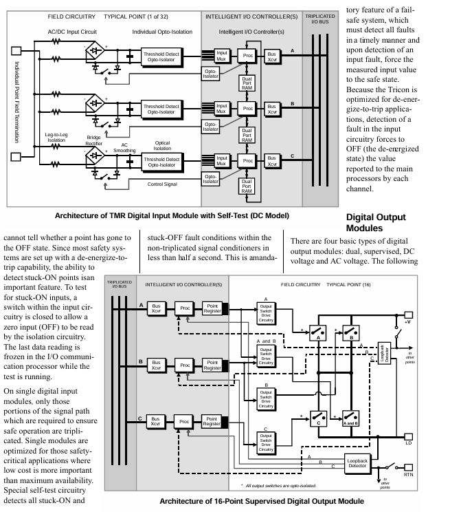
Monitoring function: By using voltage and current loop circuits, combined with online diagnosis, the output switch, on-site circuit, and load status can be verified, and faults such as on-site power loss/fuse melting, load open circuit/loss, load misoperation short circuit, load power-off short circuit, etc. can be detected; The POWER alarm is activated when the on-site voltage cannot be detected, and the LOAD alarm is activated when the load cannot be detected.

Module status diagnosis: equipped with PASS (module passes self-test), FAILT (module fault), ACTION (module activation) indicator lights, with ON/OFF status indicator lights at each point, color code Turquoise Green.

Compatibility and Installation

Supporting hot standby modules requires a separate external terminal panel (ETP) and cable interface with the Tricon backplane; The module adopts a mechanical key control design to prevent accidental installation into the wrong slot; On site wiring requires connecting the on-site power supply to each output point of the on-site terminal, with the output designed to provide current to the on-site equipment.

System configuration and hardware components

System Composition

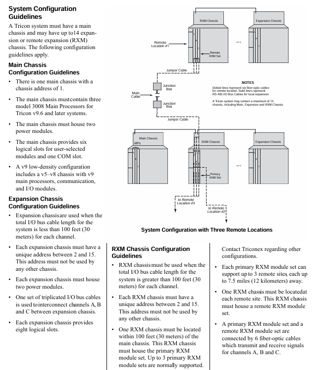
Composed of one main chassis and up to 14 extended or remote extended (RXM) chassis, up to 15 chassis can support 118 I/O modules and communication modules, and can connect OPC clients, Modbus devices, other Tricon controllers, Ethernet (802.3) external host applications, and Foxboro, Honeywell DCS.

Chassis Layout and Configuration Rules

Main Chassis: There are two power modules on the left side and three main processors on the right side. The remaining space is divided into six logical slots for I/O and communication modules, as well as one COM slot without a hot spare position. Each logical slot contains two physical spaces (active module and optional hot spare module); Address 1 requires three 3008 model main processors (Tricon v9.6 and above) and two power modules.

Expand Chassis: The layout is similar to the main Chassis, but provides 8 logical slots for I/O modules; The length of the I/O bus cable is usually up to 100 feet (30 meters), and can reach up to 1000 feet (300 meters) in restricted applications. The address needs to be between 2-15 and unique, requiring two power modules connected to channels A, B, and C through a triple I/O bus cable.

RXM Chassis: Used in scenarios where the total length of I/O bus cables exceeds 100 feet (30 meters), with addresses 2-15 and unique; An RXM Chassis needs to be located within 100 feet (30 meters) of the main Chassis, with built-in main RXM module groups (usually supporting 3 groups), each group can support 3 remote sites, with each site up to 7.5 miles (12 kilometers) away from the main site. Remote sites require RXM Chassis and remote RXM module groups, with the main and remote RXM module groups connected by 6 fiber optic cables; Provide 6 I/O module logic slots and 1 blank slot, requiring two power modules that can be connected to the local expansion Chassis via I/O bus cables.

Core hardware component specifications

Power module: each Chassis is equipped with two, and any module can operate under full load and rated temperature, supporting online replacement; Convert the line power supply to a DC power supply suitable for the Tricon module, with an input of at least 240 watts per power module; The alarm contact will activate when the module is missing, there is a conflict between hardware and control program logic configuration, the module is faulty, the main processor detects a system fault, the main power supply of the power module is faulty, or there is a warning of “low battery” or “over temperature” in the power module; There are multiple models available, such as 8310 (120 VAC/VDC), 8311 (24 VDC), 8312 (230 VAC), with an output power of 175 watts (at 140 ° F/60 ° C), an output voltage of 6.5 VDC ± 1%, a maximum output current of 27 A (in 140 ° F/60 ° C environment), input and output isolation>1000 VAC or 1500 VDC, and an over temperature sensor triggered when the internal temperature is>181 ° F (83 ° C), usually corresponding to an ambient temperature of 140 ° F (60 ° C) or above.

Main processor module (Model 3008): Used in Tricon v9.6 and above systems, each system requires 3 main Chassis modules, which independently communicate with the I/O subsystem and execute user control programs; Includes Motorola MPC860 32-bit 50 MHz microprocessor, 16 MB DRAM (without battery backup), 32 KB SRAM (battery backup), 6 MB Flash PROM; TriBus communication speed of 25 Mbps, 32-bit CRC protection, 32-bit DMA and complete isolation; The I/O bus and communication bus processors are Motorola MPC860 32-bit 50 MHz; Equipped with multiple status indicator lights such as PASS, FAULT, and ACTION; Support sequence of events (SOE) and time synchronization, protect user programs and maintain variable integrity for at least 6 months during power outages, powered by dual power modules and main Chassis power rails.

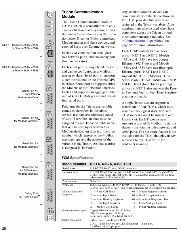
Communication module: Multiple types meet different communication needs, such as the Tricon Communication Module (TCM) that supports communication with Modbus devices TriStation PC、 Communication between network printers, other Tricon controllers, and Ethernet devices, including 4 serial ports, 2 network ports, and 1 debugging port. A single system can support up to 4 ports and should be located in two logical slots; Enhanced Intelligent Communication Module (EICM) supports RS-232/422/485 serial communication, including 4 serial ports and 1 parallel port. A single system can support up to 2 ports, which need to be located in one logical slot; The Network Communication Module (NCM) supports Ethernet (802.3) communication, including 2 BNC interfaces and 1 RS-232 serial port, supports OPC Server and TSAA protocols, and NCMG supports GPS time synchronization; The Safety Manager Module (SMM) connects Tricon to Honeywell TDC 3000 UCN; Hiway interface module (HIM) connects Tricon with Honeywell TDC 3000 Hiway gateway and LCN; Advanced Communication Module (ACM) connects Tricon with Foxboro I/A Series DCS.

Remote Expansion Module (RXM): Supports I/O modules located several kilometers away from the main Chassis, consisting of three identical modules, serving as relays and extenders for the Tricon I/O bus, providing ground loop isolation; There are multimode fiber (4200-3 main, 4201-3 remote, maximum distance 1.2 miles/2 kilometers) and single-mode fiber (4210-3 main, 4211-3 remote, maximum distance 7.5 miles/12 kilometers) models, with a communication speed of 375 kbps and indicator lights such as PASS, FAULT, and ACTION.

On site terminal options

Terminal product type

External Terminal Panel (ETP): a passive printed circuit board that facilitates on-site wiring, transmits signals between the site and I/O modules, supports I/O module replacement without interfering with on-site wiring; The on-site signals can be collected in a separate enclosure up to 99 feet (30 meters) away from Tricon; The standard panel includes terminal blocks, resistors, fuses, and other components, suitable for lines 24-12 (0.3-2.1mm ²), with some having current limiting resistors or fuses with fuse indication; There are also basic panels (including connectors and terminal blocks only, users need to equip other components themselves), hazardous area (non flammable) panels (suitable for Zone 2, Class 1, Division 2, certified by T Ü V), panels with intermediate relays (suitable for load current>2A or voltage>115 VAC scenarios), digital input bypass panels (32 pre wired switches, including master key switch and redundant 24 VDC power terminals), panels with signal conditioners (supporting RTD, thermocouple, 4-20 mA transmitter, 16 points/panel, compatible with 1-5V output signal conditioners) and other types.

Faned Out Cables: A low-cost alternative to ETP, with one end connected to a Tricon backplane and the other end having 50 labeled 22 wires with pin numbers, suitable only for digital I/O modules. The standard length is 10 feet (3 meters) and can be customized up to 99 feet (30 meters). The last two digits of the model indicate the length (feet).

Terminal configuration and protection

Configuration options: Non common ground terminal (each point can be connected to an independent power supply), common ground terminal (multiple points share one power supply, can be connected to a common ground group of 8 or 16 points); Analog signals can be connected to 3-wire transmitter inputs, voltage inputs, or current inputs; The thermocouple terminal provides a cold junction temperature sensor, the 3706A model’s fuse detection relies on the terminal panel, and the 3708E model can be configured through TriStation.

Overcurrent protection: Non basic terminal panels are self protected through single point/on-site power fuses, series resistors, digital and analog output modules; The basic terminal panel requires users to equip themselves with overcurrent protection components.

Module and Terminal Matching Table: The document provides a detailed table that lists various terminal panel models (common ground, non common ground, basic, non flammable, fan out cable, bypass panel, ERT loopback cable/panel) corresponding to each I/O module (such as digital input, digital output, pulse input, relay output, analog input, analog output, thermocouple input module, etc.). For example, the common terminal panel model corresponding to the 3624 digital output module (24 VDC, 16 points, TMR monitoring type) is 9662-610, the basic terminal panel model is 9653-610, the non flammable terminal panel model is 9671-610, and the fan out cable model is 9101-010.

Terminal panel dimensions: The document lists the width (horizontally along the DIN rail), length (vertically along the DIN rail), and height (away from the DIN rail) dimensions of each model of terminal panel, in inches and centimeters. For example, the 9551-110 panel has a width of 3 inches (7.62 centimeters), length of 5 inches (12.7 centimeters), and height of 4.25 inches (10.795 centimeters).

Communication capability

Communication range and supported objects: Tricon can communicate with Modbus master-slave devices, Foxboro I/A Series Nodebus, Honeywell UCN, Honeywell Data Hiway and LCN, Ethernet (802.3) external hosts, other Tricon controllers (peer-to-peer networks), TriStation PC, OPC Server through communication modules.

Details of Key Communication Module Functions

TCM (Tricon Communication Module): Only compatible with Tricon v10.0 and above, supporting communication with TriStation, other Tricon/Rident controllers, Modbus master-slave devices, and Ethernet external hosts; 4 serial ports (configurable as Modbus master/slave, serial port 1 supports Modbus or Trimble GPS, serial port 4 supports Modbus or TriStation, total data rate 460.8 kbps), 2 network ports (4351A/4353 is copper Ethernet, 4352A/4354 is fiber Ethernet, supports TCP/IP, Modbus TCP/IP and other protocols, network port 1 also supports peer-to-peer and peer-to-peer time synchronization protocols); A maximum of 4 units per system, located in two logical slots, do not support hot standby but can be replaced online; The Tricon variable needs to be assigned a 5-digit alias (representing the Modbus message type and variable address) to communicate with Modbus devices.

EICM (Enhanced Intelligent Communication Module, Model 4119A): Supports Modbus master-slave devices TriStation、 Printer communication; 4 serial ports (configurable as Modbus master/slave, supporting RS-232/422/485, up to 7 Modbus master stations per Chassis), 1 parallel port (Centronics compatible); A maximum of 2 units per system, located in one logical slot, do not support hot standby but can be replaced online; The total data rate is 57.6 kbps, Modbus supports RTU or ASCII mode, and Tricon variables need to be assigned aliases.

NCM (Network Communication Module, Model 4329/4329G): Supports Ethernet (802.3) communication at a speed of 10 Mbps, and NCMG supports GPS time synchronization; 2 BNC interfaces (RG58 50 ohm thin cable), 2 external transceiver interfaces (15 pin D-type), and 1 RS-232 serial port; Port 1 supports peer-to-peer and time synchronization protocols (only for Tricon secure networks), while Port 2 supports open networks (TriStation, SOE, OPC Server, etc.); A single logical slot can accommodate 2, working independently and not as a hot backup; External hosts need to access Tricon variables through aliases, which can be extended to a distance of 2.5 miles (4000 meters) through repeaters and standard cables.

SMM (Safety Manager Module, Model 4409): Connect Tricon to Honeywell TDC 3000 UCN as a safety node on the UCN, transmit process information at full network rate, and transmit Tricon alias data and diagnostic information to the operation station in a format familiar to Honeywell operators; Support critical I/O point processing, alarm processing and propagation, alias data reading and writing, Tricon diagnostic reading, write protection, DCS time synchronization, peer-to-peer communication, event sequence transmission, and hot standby functions; 2 isolated UCN ports, data rate 5 MB/s, power load<20 watts, isolated 500 VDC, equipped with multiple status indicator lights.

HIM (Hiway Interface Module, Model 4509): connects Tricon with Honeywell TDC 3000 (via Hiway gateway and LCN) or TDC 2000 (via Data Hiway), supporting communication between high-level devices on LCN/Data Hiway and Tricon; 2 isolated Data Hiway channels, baud rate of 250 kbps, equivalent to 4 extended Data Hiway port addresses, providing 8 Hiway addresses, data refresh<0.5 seconds; Support hot standby, power load<10 watts, isolated 500 VDC, with multiple status indicator lights.

ACM (Advanced Communication Module, Model 4609): connects Tricon with Foxboro I/A Series system as a secure node on Nodebus, transmitting process information at full network rate, and transferring Tricon alias data and diagnostic information to the operation station in a format familiar to Foxboro operators; Support critical I/O point processing, alarm processing and propagation, alias data read and write, Tricon diagnostic read, write protection, I/A Series time synchronization, and hot standby function; BNC supports TriStation, TSAA protocol, and user applications; Multiple ports (BNC, 15 pin D-type AUI, 9-pin RS-423 Nodebus control port, etc.), some ports have a speed of 10 Mbps, the Nodebus control port is 2400 baud, the power load is 20 watts, isolated 500 VDC, and equipped with multiple status indicator lights.

Communication Protocol and Application

Support agreement: TriStation、Modbus(RTU/ASCII/TCP)、TCP/IP、ICMP、SNTP、TSAA、Trimble GPS、 Peer to Peer, peer-to-peer time synchronization, Jet Direct (network printing), etc.

Triconex protocol: Peer to peer protocol (exchanging security and process information between Tricons), time synchronization protocol (maintaining Tricon time consistency in the network), TriStation protocol (master-slave communication between TriStation PC and Tricon, one slave per communication), TSAA protocol (master-slave communication between external hosts and Tricon, used for developing control or monitoring applications).

Triconex applications: TriStation 1131 (for developing, testing, and monitoring Tricon applications), Event Sequence (SOE, for retrieving Tricon events in the network for maintenance and downtime analysis), Enhanced Diagnostic Monitor (for monitoring Tricon hardware and application status), DDE Server (for allowing Windows DDE clients such as Excel to read and write Tricon alias data), OPC Server for Triconex (for allowing OPC clients to read and write Tricon program variables, some modules rely on external Matrikon OPC Server, and some models will have embedded OPC Server).

Network redundancy and configuration rules

Module/Media Redundancy: Install two communication modules (TCM/NCM/ACM) in the same logical slot and connect network nodes with two sets of cables to address issues such as cable breakage and port failures.

External host redundancy: The backup external host is connected to the network, and in the event of a primary host failure, the control program can be restarted on the backup host. All Triconex applications can be loaded onto the primary and backup hosts.

Configuration rule: TriStation PC needs to communicate with Tricon through TCM/EICM/NCM/ACM, and at least one such module needs to be installed in the main Chassis or Chassis 2; Some modules (such as EICM, ACM) have a limit on the number of logical slots, and some modules (such as NCM, TCM) cannot coexist in the same system; If Chassis 2 is equipped with a communication module, it requires an I/O COMM cable (9001 model) instead of a standard I/O bus cable to directly connect to the main Chassis. Chassis 2 can be an I/O expansion Chassis or a main RXM Chassis.

ABB 3BSE031151R1 PM865K01 Processor Unit HI

Core positioning and key attributes of the product

Security level and functional positioning:

Belonging to the High Integrity processor unit, it has passed SIL3 certification (compliant with safety related system standards) and needs to be configured according to the ABB safety manual; Mainly used in industrial control scenarios with extremely high security requirements, such as security systems in process industries, energy and other fields.

Core performance parameters:

The processor has a clock frequency of 96MHz and a memory capacity of 32MB. It is equipped with a memory backup battery (model 4943013-6) to ensure that critical data is not lost after power failure.

Scope of application restrictions:

Non RoHS 2 (2011/65/EU) compliant products, only used as spare parts for systems launched before July 22, 2017, for maintenance, reuse, functional updates, or capacity upgrades;

The new installation project needs to be replaced with the upgraded model PM867K01.

Product Packaging List

The delivery package of PM865K01 includes the following components and does not require additional purchase of basic accessories:

Core Unit: PM865 Safety CPU;

Basic hardware: TP830 base plate;

Bus Terminators: TB850 (CEX bus), TB807 (Modulus Bus), TB852 (RCU Link bus);

Backup accessories: 4943013-6 model memory backup battery;

Note: The packaging does not include any software license (No license included).

Physical specifications and classification information

1. Physical dimensions and weight

Specific numerical values of physical parameters

Net depth/length 135mm

Net height 186mm

Net width 119mm

Net weight 1.2kg

2. Classification of Trade and Dangerous Goods

HS code: 853710- (classified as “electronic control or distribution boards, panels, etc. equipped with two or more devices of class 85.35/85.36, with a voltage not exceeding 1000V”);

Customs tax number: 85371091;

Dangerous Goods Classification: Class 9 (Miscellaneous Hazardous Substances and Articles, including Environmentally Hazardous Substances), UN Number UN3091-PI970.

Environmental compliance and battery information

1. Environmental compliance

RoHS status: Not RoHS Compliant;

WEEE category: 5 categories (small equipment, with no external dimensions exceeding 50cm);

SCIP number: 159186b8-1923-4758-909b-dc5acB592343 (Swedish regional registration code, used for EU chemical information exchange).

2. Battery parameters

Quantity: 1 section;

Type: Portable lithium battery;

Weight: 9g;

Purpose: To provide power-off backup for processor memory and prevent data loss.

Product ownership and compatibility system

PM865K01 is the core unit of ABBAC 800M control system and 800xA system, compatible with the following specific system versions, mainly used as a spare part for the corresponding system:

AC 800M High Integrity series;

800xA system version 6.0;

AC 800M hardware versions 4.0, 4.1, 5.0, 5.1;

AC 800M control software version 4.0;

AC 800M versions 4.1, 5.0, and 5.1 under the Compact Product Suite.

GE V7768 VME Single Board Computer

Core positioning and advantages of the product

V7768 is a VME bus single board computer based on Intel architecture, featuring high flexibility and rich I/O expansion capabilities, suitable for industrial scenarios that require stable embedded computing. Its core advantages include:

Supports Intel Core 2 Duo/Celeron M processors, adapting to different performance and temperature requirements;

Integrate multiple types of interfaces (dual Gigabit Ethernet, SATA, USB, etc.) to meet basic connectivity requirements without the need for additional expansion;

Provide PCI-X PMC expansion slots and board to board connectors, which can further expand up to 3 PMC sites and adapt to complex I/O scenarios;

Compatible with mainstream operating systems such as Windows XP, VxWorks, Linux, and adaptable to various software environments.

Hardware configuration and performance parameters

1. Processor and Storage

Category specific configuration

Processor – Intel Core 2 Duo: up to 2.16GHz, 4MB L2 cache, 667MHz system/memory bus

-Intel Celeron M: 1.07GHz, 1MB L2 cache, 533MHz system/memory bus

Maximum 2GB DDR2 SDRAM memory (expandable through a single SODIMM slot)

Storage expansion supports up to 8GB CompactFlash (accessible through a secondary IDE port and configurable as a BIOS boot device)

Non volatile storage 32KB non-volatile SRAM (used to store critical data)

2. Interface and Expansion Capability

The V7768 interface covers scenarios such as network, storage, peripherals, and bus expansion, as follows:

Network interface: Dual Gigabit Ethernet (based on Intel 82571 chip), both connected through RJ45 connectors on the front panel, supporting PCIe network boot;

Storage interface: 2 SATA interfaces (leading to the rear P2 interface), used for connecting hard drives/SSDs;

USB interface: 4 USB 2.0 ports (2 front panel, 2 rear P2 ports), supporting synchronous data transfer, automatic peripheral recognition, and hot plugging;

Serial interface: 2 16550 compatible serial ports (DB-9 connector), COM1 front, COM2 rear, supporting up to 115K baud rate, including 16 byte FIFO;

Human computer interaction interface: The front panel integrates PS/2 keyboard/mouse interface and SVGA display interface;

Bus and Expansion:

VME bus: supports VME64 mode (A32/A24/D32/D08 (EO)/MBLT64/BLT32), including hardware byte swapping and enhanced bus error handling;

PMC Expansion: 1 133MHz PCI-X PMC slot, supporting VITA35 standard; By pairing the board to board connector with the PMC237CM1/V expansion board, an additional 3 32-bit/33MHz PMC stations can be added.

3. Timer and monitoring function

Programmable timers: 2 16 bit timers+2 32-bit timers, mapped to PCI memory space, supporting software programming and PCI bus interrupts;

Watchdog timer: configurable time interval, supports interrupt triggering and board level reset, improves system stability;

BIOS: The system BIOS and video BIOS are stored in programmable flash memory and support device configuration during startup.

Physical and environmental parameters

1. Physical specifications

Appearance: 6U (4HP) single slot Eurocard standard size;

Dimensions: Height 9.2 inches (233.4mm), Depth 6.3 inches (160mm), Thickness 0.8 inches (20.3mm);

Rear transition module compatibility: Supports ACC-0602RC-100 and ACC-0603RC-100 for expanding rear I/O.

2. Power requirements

+5VDC (± 5%): Typical value not labeled, maximum value not labeled (note: excluding PMC expansion slot power consumption);

+12VDC (± 5%): current<1mA;

-12VDC (± 5%): Current<1mA (VME interface allows minimum voltage -4.875V).

3. Environmental adaptability

Environmental indicator requirements

Working temperature Intel Celeron M version: 0~+70 ℃; Intel Core 2 Duo version: 0~+55 ℃

Storage temperature -40~+80 ℃

Working altitude: 0-10000 feet (3000 meters)

Storage altitude: 0-40000 feet (12000 meters)

Humidity operation/storage: 5%~95% relative humidity (non condensing)

Mandatory air cooling is required for heat dissipation, with a minimum wind speed of 400 LFM (linear feet per minute) at the outlet of the radiator

Mean Time Between Failures (MTBF) requires contacting the manufacturer for specific data

HIMatrix F30 01 Safety-Related Controller

Product Description

The safety-related F30 controller is a compact system in a metal housing with 20 digital inputs and 8 digital outputs.

The controller is available in various model variants for SILworX and ELOP II Factory.

The device is suitable for mounting in Ex-zone 2.

The device is TÜV-certified for safety-related applications up to SIL 3 (IEC 61508, IEC 61511 and IEC 62061), Cat. 4 and PL e (EN ISO 13849-1) and SIL 4 (EN 50126, EN 50128 and EN 50129).

Further safety standards, application standards and test standards are specified in the certificates available on the HIMA website.

Safety Function  

The controller is equipped with safety-related digital inputs and outputs.

Safety-Related Digital Inputs

The controller is equipped with 20 digital inputs. The state (HIGH, LOW) of each input is signaled by an individual LED.

Mechanical contacts without own power supply or signal power source can be connected to the inputs.

Potential-free mechanical contacts without own power supply are fed via an internal short circuit-proof 24 V power source (LS+). Each of them supply a group of 4 mechanical contacts.

With signal voltage sources, the corresponding ground must be connected to the input (L-)

For the external wiring and the connection of sensors, apply the de-energized-to-trip principle.

Thus, if a fault occurs, the input signals adopt a de-energized, safe state (low level).

If an external wire is not monitored, an open-circuit is considered as safe low level.

Reaction in the Event of a Fault

If the device detects a fault on a digital input, the user program processes a low level in accordance with the de-energized to trip principle.

The device activates the FAULT LED.

In addition to the channel signal value, the user program must also consider the corresponding error code.  

The error code allows the user to configure additional fault reactions in the user program.

Line Control

Line control is used to detect short-circuits or open-circuits and can be configured for the F30 system, e.g., on EMERGENCY STOP inputs complying with Cat. 4 and PL e in accordance with EN ISO 13849-1.

To this end, connect the digital outputs DO 1 through DO 8 of the system to the digital inputs DI of the same system as follows:

The controller pulses the digital outputs to detect short-circuits and open-circuits on the lines connected to the digital inputs. 

To do so, configure the Value [BOOL] -> system variable in SILworX or the DO[0x].Value system signal in ELOP II Factory. 

The variables for the pulsed outputs must begin with channel 1 and reside in direct sequence, one after the other.

If the following faults occur, the FAULT LED located on the front plate of the controller blinks,the inputs are set to low level and an (evaluable) error code is created:

 Cross-circuit between two parallel wires.

 Invalid connections of two lines (e.g., DO 2 to DI 3),

 Earth fault on one wire (with earthed ground only).

 Open-circuit or open contacts, i.e., including when one of the two EMERGENCY STOP

switches mentioned above has been engaged, the FAULT LED blinks and the error code is created. 

Equipment, Scope of Delivery

The following table specifies the available controller variants:

F30 01:Controller (20 digital inputs, 8 digital outputs), Operating temperature: 0…+60 °C, for ELOP II Factory programming tool.

F30 011 (-20 °C) :Controller (20 digital inputs, 8 digital outputs), Operating temperature: -20…+60 °C, for ELOP II Factory programming tool

F30 014:Controller (20 digital inputs, 8 digital outputs), Operating temperature: -25…+70 °C (temperature class T1), Vibration and shock tested according to EN 50125-3 and EN 50155,

class 1B according to IEC 61373, for ELOP II Factory programming tool

F30 01 SILworX:Controller (20 digital inputs, 8 digital outputs), Operating temperature: 0…+60 °C, for SILworX programming tool

F30 011 SILworX (-20 °C):Controller (20 digital inputs, 8 digital outputs), Operating temperature: -20…+60 °C, for SILworX programming tool

F30 014 SILworX:Controller (20 digital inputs, 8 digital outputs), Operating temperature: -25…+70 °C (temperature class T1), Vibration and shock tested according to EN 50125-3 and EN 50155, class 1B according to IEC 61373, for SILworX programming tool

Type Label

The type plate contains the following details:

 Product name

 Bar code (1D or 2D code)

 Part no.

 Production year

 Hardware revision index (HW Rev.)

 Firmware revision index (FW Rev.)

 Operating voltage

 Mark of conformity

Mounting the F30 in Zone 2

(EC Directive 94/9/EC, ATEX)

The controller is suitable for mounting in zone 2.  Refer to the corresponding declaration of conformity available on the HIMA website.

When mounting the device, observe the special conditions specified in the following section.

Specific Conditions X

1. Mount the HIMatrix F30 controller in an enclosure that meets the EN 60079-15 requirements and achieves a type of protection of at least IP54, in accordance with EN 60529. Provide the enclosure with the following label:

Work is only permitted in the de-energized state Exception:

If a potentially explosive atmosphere has been precluded, work can also performed when the controller is under voltage.

2. The enclosure in use must be able to safely dissipate the generated heat. Depending on the output load and supply voltage, the HIMatrix F30 has a power dissipation ranging between 12 W and 33 W.

3. Protect the HIMatrix F30 with a 10 A time-lag fuse.

The 24 VDC power must come from a power supply unit with safe isolation. Use power supply units of type PELV or SELV only.

4. Applicable standards:

VDE 0170/0171 Part 16, DIN EN 60079-15: 2004-5

VDE 0165 Part 1,   DIN EN 60079-14: 1998-08

Configuration with SILworX

In the Hardware Editor, the controller is represented like a base plate equipped with the  following modules:

 Processor module (CPU)

 Communication module (COM)

 Input module (DI 20)

 Output module (DO 8)

Double-click the module to open the Detail View with the corresponding tabs. The tabs are used to assign the global variables configured in the user program to the system variables.

Parameters and Error Codes for the Inputs and Outputs

The following tables specify the system parameters that can be read and set for the inputs and outputs, including the corresponding error codes.

In the user program, the error codes can be read using the variables assigned within the logic.

The error codes can also be displayed in SILworX.

Configuration with ELOP II Factory

Configuring the Inputs and Outputs

The signals previously defined in the Signal Editor (Hardware Management) are assigned to the individual channels (inputs and outputs) using ELOP II Factory. Refer to the system manual for compact systems or the online help for more details.

The following chapter describes the system signals used for assigning signals in the controller.

Signals and Error Codes for the Inputs and Outputs

The following tables specify the system signals that can be read and set for the inputs and outputs, including the corresponding error codes.

In the user program, the error codes can be read using the signals assigned within the logic.

The error codes can also be displayed in ELOP II Factory.

Operation

The controller F30 is ready for operation. No specific monitoring is required for the controller.

Handling

Handling of the controller during operation is not required.

Diagnosis

A first diagnosis results from evaluating the LEDs, see Chapter 3.4.1.

The device diagnostic history can also be read using the programming tool.

Maintenance

No maintenance measures are required during normal operation.

If a failure occurs, the defective module or device must be replaced with a module or device of the same type or with a replacement model approved by HIMA.

Only the manufacturer is authorized to repair the device/module.

Faults

If the test harnesses detect safety-critical faults, the module enters the STOP_INVALID state and will remain in this state. This means that the input signals are no longer processed by the device and the outputs switch to the de-energized, safe state. The evaluation of diagnostics provides information on the fault cause.

Maintenance Measures

The following measures are required for the device:

 Loading the operating system, if a new version is required

 Executing the proof test

Loading the Operating System

HIMA is continuously improving the operating system of the devices.

HIMA recommends to use system downtimes to load a current version of the operating system into the devices.

Refer to the release list to check the consequences of the new operation system version on the system!

The operating system is loaded using the programming tool.

Prior to loading the operating system, the device must be in STOP (displayed in the programming tool). Otherwise, stop the device.

For more information, refer to the programming tool documentation.

Proof Test

HIMatrix devices and modules must be subjected to a proof test in intervals of 10 years.

Decommissioning

Remove the supply voltage to decommission the device. Afterwards pull out the pluggable screw terminal connector blocks for inputs and outputs and the Ethernet cables. 

Transport

To avoid mechanical damage, HIMatrix components must be transported in packaging.

Always store HIMatrix components in their original product packaging. This packaging also provides protection against electrostatic discharge. Note that the product packaging alone is not suitable for transport.

Disposal

Industrial customers are responsible for correctly disposing of decommissioned HIMatrix hardware. Upon request, a disposal agreement can be arranged with HIMA.

All materials must be disposed of in an ecologically sound manner. 

Welker Bearing Linear Guides and Wedge Components

​Product basic positioning and core application areas

1. Product category and positioning

The linear guide and wedge components of Welker Bearing are both high-precision linear motion parts, with the core positioning being:

Linear Slides: Achieve smooth and precise linear reciprocating motion of equipment components, undertaking dual functions of guidance and load-bearing;

Gib Assemblies: Used in conjunction with linear guides to adjust guide clearance, compensate for wear, improve motion accuracy and stability, and some models can be used independently as guide components.

2. Core application scenarios

Both types of products focus on the demand for “high-precision linear motion” in the industrial field, and typical application equipment includes:

Machine tools: worktable guidance for lathes, milling machines, grinders, and machining centers;

Automation equipment: robot guide rails, automated production line conveyor mechanisms, precision positioning platforms;

Heavy industrial equipment: linear moving parts of metallurgical machinery, heavy-duty presses, and mining equipment;

Special equipment: precision guide rails for aerospace component processing equipment and medical imaging equipment (such as CT and MRI).

Product details of Linear Slides

1. Product series classification

According to the structure, load-bearing capacity, and accuracy level, linear guides are divided into multiple standard series. The core series and characteristics are as follows:

Series name, structural characteristics, core advantages, applicable scenarios

Standard Linear Slides single/double track structure, using steel guide rails and sliders, with built-in lubrication grooves for strong versatility, moderate cost, easy installation, universal machine tools, and lightweight automation equipment

Heavy Duty Linear Slides: Thickened guide rail walls, reinforced slider materials (high carbon steel/alloy steel), multiple sets of rolling elements (or sliding friction pairs) with strong load-bearing capacity (static load can reach several tons), good impact resistance. Heavy duty machine tools, metallurgical machinery, and press machines

Precision Linear Slides (Precision Series) guide rail surface precision grinding (roughness Ra ≤ 0.8 μ m), adjustable clearance, equipped with position feedback interface (optional), high motion accuracy (positioning error ≤ 0.01mm/m), good repeatability Precision machining equipment, medical equipment, aerospace parts processing

Custom Linear Slides can adjust the length of guide rails, number of sliders, installation hole positions, and material (such as stainless steel) according to customer needs to adapt to special installation spaces and working conditions. Non standard equipment and customized scenarios for special industries can also be used

2. Key technical parameters (general standards)

(1) Dimensions and installation parameters

Guide rail length: Standard series 6 inches (152.4mm) -10 feet (3048mm), custom series can be extended to 20 feet (6096mm) or more;

Guide rail cross-sectional dimensions: standard width of 1.5 inches (38.1mm) -6 inches (152.4mm), height adapted to load-bearing capacity (1 inch -4 inches);

Installation method: Bottom/side bolt fixation, standard installation hole spacing of 12 inches (304.8mm), customizable hole distribution.

(2) Performance parameters

Performance Index Standard Series Heavy duty Series Precision Series

Maximum Static Load Capacity: 500-2000 lbf (2.22-8.89 kN) 2000-10000 lbf (8.89-44.48 kN) 800-3000 lbf (3.56-13.34 kN)

Maximum rated dynamic load capacity: 300-1500 lbf (1.33-6.67 kN) 1500-8000 lbf (6.67-35.59 kN) 500-2500 lbf (2.22-11.12 kN)

Position Accuracy ± 0.005 inches/foot (± 0.42mm/m) ± 0.01 inches/foot (± 0.84mm/m) ± 0.001 inches/foot (± 0.084mm/m)

Maximum Speed: 500 inches/minute (12.7m/min), 300 inches/minute (7.62m/min), 800 inches/minute (20.32m/min) (compatible with precision drives)

(3) Material and Protection

Material of guide rail/slider: Standard material is 1045 high carbon steel (quenched hardness HRC 58-62), precision series can choose 440C stainless steel (rust proof), heavy-duty series can choose alloy structural steel;

Surface treatment: The standard is blackening treatment (rust prevention), optional chrome plating (enhanced wear resistance), zinc plating (corrosion resistance, suitable for humid environments);

Lubrication: Built in lubrication groove, supports regular lubrication grease (lithium based grease is recommended), and some models can choose automatic lubrication interface.

Gib Assemblies Product Details

1. Product type and structure

Wedge components, as the “precision compensation and clearance control components” of linear guides, are mainly divided into two categories:

Type Name Structure Composition Core Functions

Solid Gibbs integrated wedge block (inclined angle 3 ° -10 °), fixing bolt, and locating pin are used to fix the guide rail clearance, suitable for scenarios with low wear and stable working conditions

Adjustable Gibs: Split wedge block (active wedge+passive wedge), adjusting bolt (top screw/pull rod), locking nut can adjust the gap in real time (compensating for wear or assembly errors), suitable for high-precision or high wear working conditions

2. Key technical parameters

Material: Same linear guide rail, mainly made of 1045 high carbon steel (quenched HRC 55-60), optional stainless steel;

Slope accuracy: Slope angle tolerance ± 0.5 °, surface roughness Ra ≤ 1.6 μ m;

Adjustment range: The gap adjustment of the adjustable wedge block is 0.001-0.01 inches (0.025-0.254mm), meeting different precision compensation requirements;

Adaptive guide rail: It can be matched with Welker’s full range of linear guides, and can also be customized according to the customer’s existing guide rail size (a cross-sectional view of the guide rail is required).

Customized services and design support

1. Customized service scope

Welker Bearing provides comprehensive customized solutions, with core customization content including:

Customization of dimensions: rail length, cross-sectional dimensions, installation hole positions/quantities;

Material and surface treatment customization: stainless steel material (rust proof), special alloy (high temperature/corrosion resistance), customized surface coating (such as PTFE coating for friction reduction);

Function customization: Add position sensor interface (such as grating ruler installation slot), integrate dust cover (anti debris/dust), design special lubrication system (automatic lubrication);

Adaptability customization: Design non-standard wedge components or rail structures based on the installation space and load-bearing requirements of the customer’s existing equipment rails.

2. Design support services

Technical consultation: Provide linear motion scheme evaluation to assist customers in selecting suitable product series;

Drawing support: Provide 2D (CAD)/3D (SolidWorks) model drawings for customers to integrate into equipment design;

Sample production: Customized products can provide sample testing (sample fee required, refundable after bulk order);

Installation guidance: Provide installation manuals and videos, and if necessary, dispatch engineers to provide on-site guidance for installation.

GE Multilin MIF series digital feeder relay

Product basic positioning and core applications

1. Product type and positioning

The MIF series belongs to the M Family (M series) digital feeder relay, which is divided into two core models according to the protected object:

MIF-P type: three-phase+grounding protection relay, suitable for comprehensive protection of three-phase distribution circuits;

MIF-N type: single-phase or ground protection relay, focusing on single-phase circuit or ground fault special protection.

2. Core application scenarios

Main protection: Main circuit protection for various voltage levels of distribution networks, covering lines, distribution equipment, etc;

Backup/auxiliary protection: Backup protection for transformers, generators, and motors to compensate for blind spots in main protection;

Control and Monitoring: Cooperate with circuit breakers to achieve remote control, while providing electrical parameter measurement and equipment status monitoring.

Core functions and technical features

1. Protection function (core highlight)

The MIF series focuses on “overcurrent protection” and is equipped with various specialized protections to adapt to different fault scenarios

(1) Overcurrent protection (TOC/IOC)

Protection type applicable model key parameters and characteristics

Phase TOC MIF-P (three-phase), MIF-N (single-phase) – Setting range: 0.1-2.4 times rated current (I n)

-Curve selection: 4 standard curves (corresponding to ANSI/IEC)+1 user-defined curve, supporting time multiplier adjustment

-ANSI corresponds to IEC curves: Normal Inverse Time (ANSI) → IEC A, Extraordinary Inverse Time → IEC B, Extreme Inverse Time → IEC C, Timed Limit → Timed Limit

Ground TOC MIF-P (standard), MIF-N (optional) – Curve and parameter settings for in-phase overcurrent protection

-Grounding signal acquisition: By default, the residual current of three-phase CT is summed up (without the need for additional sensors); Sensitive scenes can be paired with zero sequence grounded CT (surrounding three-phase conductors) to improve detection accuracy

Instantaneous Overcurrent (IOC) Full Model – Independent Configuration: MIF-P includes 2 sets of three-phase IOC+2 sets of grounded IOC, MIF-N includes 2 sets of single-phase/grounded IOC

-Setting range: pickup (0.1-30 times I n), delay (0-100 seconds), supports individual enable/disable

(2) Other special protections

Thermal Image Protection: prevents equipment from being damaged due to overload and overheating, with a constant heating time

T1 (adjustable from 3-600 minutes), cooling time constant T2 (adjustable from 1-6 times T1), suitable for different device heat dissipation characteristics;

Cold Load Pickup (optional): Automatically adjust the overcurrent setting value when powering on again to avoid triggering the protection by overload current;

Breaker Failure Protection (optional): The basic function is to detect that the circuit breaker has not been opened; Complex solutions can be implemented through digital inputs and configurable output logic (logic gates, timers);

Breaker Health Monitoring (optional): Users set a cumulative current threshold, triggering an alarm when the threshold is exceeded, achieving “on-demand maintenance”.

2. Control and operation functions

Circuit breaker control: supports circuit breaker opening/closing operations, triggered by programmed output terminals, and verified by digital input terminals to ensure successful operation;

Two Settings Groups: Two sets of protection parameters can be pre-set to adapt to different operating conditions (such as normal load/peak load);

On site upgrade: Designed with Flash Memory, it supports firmware upgrade through communication or software on-site, without the need to disassemble the device.

3. Monitoring and metering functions

Event recording: Store 32 event records, record key events such as faults and operations, for easy fault tracing;

Waveform recording: supports analog/digital waveform recording, captures instantaneous changes in electrical parameters during faults, and assists in fault analysis;

Dual end metering: CT transformation ratio can be set, and the primary and secondary current measurement values can be monitored simultaneously to meet the data requirements of operation and maintenance.

4. Hardware and interface characteristics

Power adaptation: Supports AC/DC universal power supply, covering 24-48V DC/AC, 110-250V DC, 110-230V AC (specific range see ordering parameters);

Communication interface: Front end RS232 port (local debugging), back-end RS485 port (remote communication), both support ModBus ®  RTU protocol, with a maximum speed of 19200 bps;

I/O configuration: comes standard with 2 digital inputs and 6 relay outputs (4 programmable), and can customize output logic (OR/NOT combination) through M+PC software;

Mechanical structure: Drawout case for easy maintenance; Compatible with M-series 19 inch half rack/full rack installation, compatible with system integration.

5. Software and user interaction

Configuration software: supports M+PC software (parameter settings, status monitoring), enerVista.com platform (remote management, see page 275 of the document for details);

Local operation: Front panel buttons for direct parameter adjustment and status viewing;

Indicator lights (LEDs): LED indicator lights can be configured to visually display the device’s operating status and fault type.

Wiring and safety regulations

1. Typical wiring reference

Grounding detection wiring: Two options are available – ① Three phase CT residual current summation (no additional sensors required); ② Zero sequence grounding CT (sensitive detection scenario);

Current input: It is recommended to use a 14 AWG (2.5mm ²) wire, and the terminal should be a fork or ring terminal;

Safe grounding: It is necessary to connect to a safe ground. Terminals B12, A12, and B11 are only for connecting SELV (safety extra low voltage) components (such as PLC), and withstand voltage testing is prohibited.

2. Safety Tips

Overvoltage category: Class II, suitable disconnect devices (switches or circuit breakers) need to be installed near the relay;

Internal fuse: The power circuit is equipped with a 1A/250V fast fuse to protect the equipment in case of malfunction.

Ordering information (model coding rules)

The MIF series model code format is * * MIF * * * * E * 00 * 00 * * *, and the meanings of the characters in each position are as follows, which need to be combined according to actual needs:

Encoding Position Optional Character Meaning Explanation

1st to 3rd digit MIF product identification (digital feeder relay)

The 4th P/N P=three-phase+grounding relay; N=single-phase or grounded relay

5th A/I A=ANSI standard curve; I=IEC standard curve

6th position 0/1/5=MIF-N type; 1=MIF-P type (I n=1A, setting range 0.1-2.4A); 5=MIF-P type (I n=5A, setting range 0.5-12A)

7th position 1/5/N grounding CT rated current: 1=1A (0.1-2.4A); 5=5A(0.5-12A); N=sensitive grounding (1A, 0.005-0.12A)

8th position (empty)/1/2 empty=base model (no options); 1=Option 1 (configurable I/O, event logging, recording); 2=Option 2 (including option 1 function+cold load input, circuit breaker failure/health monitoring, configurable logic)

The power specifications for positions 9-10 are 24-48V DC/AC (19-58V DC); 110-250V DC(88-300V DC); 110-230V AC(88-264V AC)

The installation method for positions 11-12 is empty=independent relay; M+=Installed on M+system (requires additional order of M050 half 19 inch rack or M100 full 19 inch rack, provided free of charge according to the number of relays)

Example

MIF P A 1 1 2 110: Three phase+grounding relay (P), ANSI curve (A), phase CT I n=1A (1), grounding CT I n=1A (1), including option 2 function (2), 110-250V DC power supply (110).

ABB MNSiS Motor Control Center MConnect Interface

Core positioning and scope of application

Associated System: Designed specifically for MNS iS System Release 7.6 to guide communication and control integration of MConnect interfaces, supporting the integration of MNS iS as a fieldbus component into PLC or higher-level process control systems (PCS/DCS).

Target users: Control and application engineers who need to obtain MNS iS data and perform system integration, requiring users to have basic knowledge of fieldbus (such as PROFIBUS, Modbus).

Basic concepts and terminology definitions

The document provides explanations for over 30 core terms and abbreviations, covering technical terms, protocols, components, etc. The key terms are as follows:

Abbreviations/full names of terms/Chinese core explanation

Aspect Object ABBAspect is a computerized representation of real/virtual objects (such as pumps, services) that are described and structured through “attributes”

Standardized products that can be directly purchased and used in the COTS commercial spot product market

DTM Device Type Manager is a software module used to manage devices through fieldbus (such as PROFIBUS), supporting frameworks such as PactWare

GSD file device description file (German) PROFIBUS-DP/DP-V1 slave station hardware description file, used for device configuration

MCC motor control center is a switchgear used for motor control and protection, which is one of the core application scenarios of MNS iS

MODBUS RTU Modbus Remote Terminal Unit Protocol Fieldbus Communication Protocol, the core protocol for MConnect and circuit breaker communication

PNIO PROFINET IO is an open standard based on industrial Ethernet (IEC 61158/61784) used for distributed peripheral devices and automation

The SNTP Simple Network Time Protocol is a protocol that controls network time synchronization through Ethernet

The remaining terms (such as HMI, LVS, OPC, etc.) revolve around low-voltage switchgear, communication protocols, and system components, laying the foundation for subsequent technical content.

Hardware and software requirements

1. Hardware requirements

(1) MConnect hardware model and configuration

The MConnect hardware is based on the motherboard and is paired with different functional modules (analog input/output, digital input/output, PT100 temperature acquisition) to form 28 models. The core model identification rules are as follows (taking the 1TGE120071R series as an example):

Model ID Core Configuration Function Extension

1TGE120071R1000 motherboard only, no additional IO or temperature acquisition

1TGE120071R1001 motherboard+AIAO (Analog IO) supports analog signal input and output

1TGE120071R1100 motherboard+4DI2DO (24VDC digital IO) with 4 digital inputs and 2 digital outputs (24V DC)

1TGE120071R1500 motherboard+7DI0DO (110VAC-230VAC) 7-channel digital input, no digital output (110-230VAC AC)

1TGE120071R1600 motherboard+PT100-3CH supports 3-channel PT100 temperature acquisition (for control only, non protective function)

(2) Key hardware components

Control Condaptor: A specialized component (model 1TGE102069R0661) used to connect MConnect to MNS iS system, requiring address setting (cabinet number=circuit breaker cabinet number, level=1, position=1).

Communication interface: MConnect is connected to the circuit breaker through RS485 bus, with built-in bus bias and terminal resistance; An external 120 Ω (0.25W) terminal resistor is required on the circuit breaker side to ensure communication stability.

2. Software requirements

Basic version: MConnect requires a basic version of 7.6 or higher to fully support the functionality of MNS iS V7.6.

Auxiliary tools: Parameter settings need to be done in conjunction with MNavigate (Configuration and Management Tool), and some functions can be found in the MNavigate help documentation (such as hardware option usage).

Circuit breaker integration solution

The circuit breaker is the core component of the MNS iS cabinet, and MConnect achieves its monitoring and control through the following methods:

1. Supported circuit breakers and programmable release devices

Remarks on Programmable Release Devices (PR Units) Supported by Circuit Breaker Types

Emax PR122/P, PR123/P classic series, corresponding to PR12x series release

Emax X1, Tmax T7/T7M PR332/P, PR333/P upgrade series, corresponding to PR33x series release

Emax2 Ekip Touch, Ekip Hi Touch, Ekip G Touch, Ekip G Hi Touch intelligent series, supporting richer state and data collection

2. Communication architecture and connections

Communication role: MConnect serves as the Modbus RTU master and communicates point-to-point with the programmable release of the circuit breaker (Modbus slave) through RS485; At the same time, as a gateway, it communicates with MLink through the internal “Switchgear Bus” (10Base-T Ethernet) of MNS iS.

System limitation: Following the MNS iS design rules, each MLink can connect up to 60 devices (including MConnect and MControl), distributed in up to 7 cabinets.

Physical connection: The RS485 bus adopts a three wire system (A/W1, B/W2, shielded wire), and the terminal definitions of different circuit breakers are unified (for example, the A/B terminals of Emax and Emax2 are all W1/W2). Please refer to the document “1SDC007108G0201” for details.

3. Configure parameters

The Modbus interface parameters of MConnect need to be consistent with the circuit breaker release, and the parameter settings are as follows:

Parameter optional range, default value description

Slave Address 2-247 247 needs to be configured the same as the PR unit of the circuit breaker

Baudrate rate 9600/19200 bps 19200 bps communication rate, needs to match PR unit settings

Protocol parity check 1 stop bit, odd parity check 1 stop bit, no parity check 2 stop bit, no parity check 1 stop bit, even parity check 1 stop bit. The format of the data check and stop bit should match the PR unit

Attention: The MConnect main site address is fixed at 1 and cannot be modified by users; Only supports “point-to-point” communication and does not support multiple bus slaves.

Data and Command Interaction

The document provides a detailed definition of data collection (status, measurement values, alarm/trip information) and control commands for MConnect and two types of release devices (PR12x/PR33x, Ekip). The core content is as follows:

1. PR12x/PR33x series release

(1) Status data (32-bit unsigned number, Motorola byte order)

Device status bits: There are a total of 16 bits, with key bits meaning “open (Bit0), closed (Bit1), tripped (Bit2), undefined (Bit3), discharged (Bit4)”, and the remaining bits reserved (set to 0).

Extended Status Flag: Contains 8 types of flags, including State 2-9, covering alarm/trip (such as “any alarm” and “circuit breaker trip”), operating mode (local/remote), communication status (no communication on local bus), programming status (successful/failed programming), etc. Each type of flag is a 16 bit unsigned number (UWORD).

(2) Measurement value

Covering over 20 electrical parameters such as current, voltage, power, frequency, and energy, examples are as follows:

Measurement item data type unit invalid value explanation

L1 phase current (effective value) ULONG (unsigned long integer) A 0xffffffff current displays 0 when<minimum value, and displays maximum value when>maximum value

Line voltage V12 (effective value) UWORD-10 (10 times unsigned short integer) V 0xffff displays 0 when voltage<minimum value, and displays maximum value when voltage>maximum value

Total active power (signed) LONG_10 (10 times integer) kW 0x7ffffffff Display 0 when power<minimum value, display ± maximum value when out of range

Frequency UWORD_10 (10x unsigned short integer) Hz 0xffff: When the frequency is less than the minimum value, the minimum value is displayed, and when it is greater than the maximum value, the maximum value is displayed

Total active energy (signed) LONG kWh – cumulative energy value, supporting forward/reverse metering

(3) Alarm and trip information

By defining the STATE 4-6 (alarm) and STATE 8-9 (trip lock) flag bits, it covers over 30 abnormal scenarios such as “harmonic distortion exceeding 2.1”, “contact wear alarm”, “overvoltage trip”, “hardware fault trip”, etc. Each scenario corresponds to a specific bit (setting 1 indicates triggering).

2. Ekip series release (Emax2 specific)

(1) Status and measurement values

Status difference: The device status bit only retains “disconnected (Bit0), closed (Bit1), tripped (Bit2), undefined (Bit3)”, and the remaining bits are reserved; The extended state is divided into four categories: global state (such as circuit breaker closure/isolation), timing state (such as L/S/G timing triggering), trip state (such as overload trip), and warning/alarm state (such as sensor error), covering more detailed intelligent monitoring scenarios.

Measurement value expansion: Added parameters such as “RC current (external grounding current)”, “power factor (in kiloparts)”, “PT100 temperature”, etc., with data types compatible with PR12x/PR33x.

(2) Additional information collection

Support the full lifecycle data of circuit breakers, such as “Circuit Breaker Serial Number (16 bit ASCII)”, “Installation Date/Last Maintenance Date (seconds from December 31, 1999)”, “Operation Times (Opening Count)”, “Contact Wear Percentage (0-65000 corresponds to 0% -100%)”, etc., for easy maintenance and management.

3. Control commands (universal)

Only when the circuit breaker release is manually switched to “remote mode” (password required), the following commands can be sent through the MLink fieldbus:

Command function

CB Close Circuit Breaker Close

CB Open circuit breaker disconnected

CB Reset Circuit Breaker Reset

Trip Reset resets the trip records stored in the release device

Wink Toggle Command Circuit Breaker Identification (Tripper Display Flashing)

NOP no operation (no action)

4. Data validity (quality code)

Identify data validity through “QualityCode1” and “QualityCode2” (32-bit unsigned numbers):

Bit=0: Data is valid; Bit=1: Invalid data.

QualityCode1 covers measurement values (such as current, voltage, power), while QualityCode2 covers status indicators (such as alarm, trip) and equipment information (such as serial number, rated current).

Circuit breaker type decoding

The document provides decoding tables for two types of circuit breakers (TAB_CB.TYPE, TAB_CB.TYPE_33x), and specifies the specifications of the circuit breakers through a “numerical model” mapping. The example is as follows:

Decoding type, numerical circuit breaker model, numerical circuit breaker model

TAB_CB-TYPE (Emax series) 0 E1B800/3P 1 E1B800/4P

28 E2S800 / 3P 29 E2S800 / 4P

88 E4S4000 / 3P 89 E4S4000 / 4P

TAB_CB-TYPE_33x (Tmax/X1 series) 0 T7S800/3P 1 T7S800/4P

30 X1B800 / 3P 31 X1B800 / 4P

60 T7H1200 / 3P 61 T7H1200 / 4P

Note: “3P/4P” in the model indicates 3 poles/4 poles, and numbers (such as 800, 1200) indicate specifications related to rated current.

Emerson PR6426 32mm Eddy Current Sensor

Product positioning and application

PR6426 is a non-contact 32mm eddy current sensor designed for critical turbomachinery applications, which can be used to measure radial and axial shaft displacement, including position, eccentricity, and motion. It is suitable for equipment including steam turbines, gas turbines, water turbines, compressors, pumps, and fans.

Core performance parameters

(1) Dynamic performance

Specific specifications of parameters

Sensitivity 2 V/mm (50.8 mV/mil), maximum deviation ≤± 1.5%

The nominal air gap (center) is approximately 5.5 mm (0.22 inches)

Long term drift<0.3%

Static measurement range ± 4.0 mm (0.157 inches)

(2) Target requirements

Target/Surface Material: Ferromagnetic Steel (Standard 42 Cr Mo 4)

Maximum surface velocity: 2500 m/s (98425 ips)

Shaft diameter: ≥ 200 mm (7.87 inches)

Environmental adaptability

Environmental parameter specification requirements

Working temperature range -35 to 175 ° C (-31 to 347 ° F)

Short term (<4 hours) temperature fluctuation up to 200 ° C (392 ° F)

The maximum temperature of the cable is 200 ° C (392 ° F)

Temperature error (23 to 100 ° C) Zero point: -0.3%/100 ° K; Sensitivity:<0.15%/10 ° K

Sensor head pressure resistance 6500 hPa (94 psi)

Anti impact and vibration performance 5g (49.05 m/s ²) at 60Hz, 25 ° C (77 ° F)

Physical characteristics

Material: The sleeve is made of stainless steel, and the cable is made of polytetrafluoroethylene (PTFE)

Weight: Approximately 800 grams (28.22 ounces) of sensor and 1 meter of unarmored cable

Cable related: made of 2.8mm PTFE cable; The minimum bending radius of armored cables is 31mm, and the minimum bending radius of non armored cables is 25mm. The standard total cable length is 1 meter, and there are also typical lengths such as 4 meters, 5 meters, 8 meters, and 10 meters to choose from

Structural details: A 80mm diameter non-magnetic material free area needs to be reserved; Equipped with LEMO connector adapter; The sensor identification is covered by a heat shrink tubing; There are 2 8.3mm holes for installing M8 × 20 DIN 933 A2 80A bolts and 8.3mm DIN 463 washers; The end is an epoxy resin cap

Compliance and Certification

Certification type follows standards

CE certification 2014/30/EU (EN 61326-1), 2014/34/EU, 2011/65/EU

ATEX certification EN 60079-0, EN 60079-11

IEC Ex certification IEC 60079-0, IEC 60079-11, IEC 60079-26

CSA Certification  CAN/CSA-C22.2 NO. 0-M91、CAN/CSA-C22.2 NO. 157-92、CAN/CSA-C22.2 NO. 213-M1987、CAN/CSA-E60079-15-02(R2006)、CAN/CSA-C22.2 NO. 25-1966、CAN/CSA-C22.2 NO. 61010-1-04、ANSI/UL Standard 913-2004、ANSI/UL Standard 1604-1995、UL 60079-15 2002、UL 61010-1

Hazardous Area Certification

Inherent Safety (iA)

Certification system requirements

The ATEX/IEC Ex area classification depends on the converter, as detailed in the converter documentation; Sensor temperature classification: T6 (Ta ≤ 84 ° C), T4 (Ta ≤ 114 ° C), T3 (Ta ≤ 160 ° C)

The classification of CSA regions depends on the converter, as detailed in the converter documentation; Sensor temperature classification: T6 (Ta ≤ 64 ° C), T4 (Ta ≤ 114 ° C), T3 (Ta ≤ 160 ° C)

The document does not mention specific and detailed requirements.

Order Matrix

The order model format is PR6426/X X X – X X X, and the meaning of each location code is as follows:

Sleeve thread: No thread (code 0)

Armored cable: with armor (code 1), without armor (code 0)

Total sensor length: mounting plate 80mm × 40mm (code 0)

Adapter plug: No adapter plug (code 0), with adapter plug (code 1)

Total cable length: 4 meters (code 0), 5 meters (code 1), 6 meters (code 2), 8 meters (code 3), 10 meters (code 4)

Cable end: LEMO interface (code 0), open (code 1)

image.png

Schneider ELAU PacDrive C400/C400 A8 Controller

Product core positioning and system architecture

1. Core positioning

The PacDrive C400/C400 A8 is a high-performance motion controller based on a real-time operating system, designed specifically for industrial equipment that requires multi axis synchronization and precise positioning. Its core function is to coordinate servo drives to complete complex motion control tasks (such as cam synchronization, electronic gears, and multi axis interpolation), while supporting logic control and industrial communication, and adapting to automated production lines such as packaging, printing, and assembly.

2. System architecture

Hardware Core: Equipped with Intel processors (C400 for Pentium M 600MHz, C400 A8 for Celeron M 600MHz), 256MB RAM, 128kB NVRAM, and ≥ 128MB CompactFlash card (for program storage and data backup), ensuring real-time computation and data stability.

Real time operating system: Equipped with VxWorks real-time system, it has fast response speed, supports multitasking parallel processing, and meets the demand for “microsecond level” real-time performance in motion control.

Core bus: Connected to servo drives through SERCOS real-time motion bus (C400 supports up to 16 SERCOS slave stations, C400 A8 supports up to 8), achieving multi axis synchronous control; Simultaneously equipped with fieldbus such as PROFIBUS DP and CANopen, balancing logic control and device interconnection.

Core functions and technical features

1. Motor control ability

Multi axis control: C400 supports 16 servo axes, and C400 A8 supports 8 servo axes. All axes are compatible with full cycle control of SERCOS bus (such as 1ms/2ms/4ms cycle), which can achieve complex movements such as electronic gear, electronic cam, and multi axis interpolation, meeting high-precision synchronization requirements (such as film traction and cutter synchronization of packaging machines).

Cam and sequence control: Supports up to 256 dynamic cam groups, and cam curves can be customized through software; Sequence control supports three modes of “continuous/cycle/event triggering”, adapted to the step-by-step action logic of the production line (such as workstation switching on the assembly line).

Position detection and feedback: equipped with 1 SinCos main encoder interface and 1 incremental main encoder interface (X11), supporting external position feedback; Simultaneously providing 16 Touchprobe trigger inputs (X4) with a resolution of 100 μ s, it can achieve precise positioning capture (such as product positioning detection).

2. Logic control and I/O expansion

PLC function: Supports IEC 61131-3 standard programming language (instruction list IL, ladder diagram LD, function block diagram FBD, structured text ST, etc.), can simultaneously handle motion control and logic control tasks (such as equipment start stop, safety interlock, fault diagnosis); PLC instruction execution speed is fast, with only 7 μ s required for 1000 instructions and a fast task cycle of up to 250 μ s.

Local I/O configuration:

Digital input: 20 channels (DC 20-33V, supporting 1/5ms parameterized filtering), used for detecting sensor signals (such as photoelectric switches, limit switches).

Digital output: 16 channels (DC 20-30V, rated current 250mA per channel, short circuit protection), used to control actuators (such as solenoid valves, indicator lights).

Analog I/O: 2 analog inputs (-10~10V or 0~20mA, 12 bit resolution), 2 analog outputs (-10~10V, 12 bit resolution), compatible with analog devices such as pressure sensors and proportional valves.

Fast I/O: 4-channel interrupt input (X4, 0.1/1ms filtering), used to process high-speed trigger signals (such as emergency stop, safety door signals).

Scalability: Up to 128 digital inputs/outputs and 128 Touchprobe inputs can be expanded through the PacNet interface; Through PROFIBUS DP, 126 slave stations can be connected, with a maximum expansion of 3584 bytes of digital/analog I/O, meeting the signal acquisition and control requirements of large-scale production lines.

3. Industrial communication and data exchange

Communication interface:

Motion bus: SERCOS (16MBaud), used for connecting servo drives to achieve multi axis synchronization.

Fieldbus: PROFIBUS DP (master/slave mode, 12MBaud), CANopen, DeviceNet (adapter required), EtherNet/IP (optional hardware module required), supporting interconnection with PLC, HMI, sensors and other devices.

General communication: RS232 (COM1), RS485 (COM2), Ethernet (10/100Base-T, supporting TCP/IP), used for program download, data monitoring, and remote maintenance.

Data exchange and remote services:

Built in OPC server, supports real-time data access for Windows based HMI (such as Schneider Vijeo Designer), and realizes device status visualization.

Support remote services between web servers and modems, enabling device diagnostic information to be obtained through browsers or SMS (SMTP protocol), simplifying on-site maintenance.

Integrated data logger (27kB) and trajectory logger (8 channels, 1ms resolution), capable of recording fault information and motion curves for troubleshooting and process optimization.

Hardware specifications and environmental adaptability

1. Electrical and mechanical parameters

Category specific specifications

The power requirement is DC 24V (-15%~+25%), with a maximum current of 3A without UPS and 4.5A with UPS. The maximum power consumption is 85W

The protection level of the shell is IP20, suitable for installation inside the control cabinet; Pollution level 2, suitable for industrial dust environment

Size and weight: Packaging size 300 × 130 × 400mm (D × W × H), with packaging weight of 3.5kg (C400)/4.1kg (C400 A8)

Isolation and anti-interference comply with the IEC 61000-6-2 electromagnetic interference standard, supporting shielded cable connections to reduce signal interference

Diagnostic and monitoring alphanumeric diagnostic display screen, status LED indicator light; Watchdog function (maximum 60V/2A), triggers relay in case of malfunction

2. Environmental adaptability

Scene temperature range, humidity range, and other requirements

Normal operation+5 ℃~+45 ℃ (C400); +5 ℃~+40 ℃ (with UPS) 5%~85% RH (no condensation) No freezing or water ingress allowed

Transportation -25 ℃~+70 ℃ (C400); -25 ℃~+50 ℃ (with UPS) 5%~95% RH (without condensation) Prohibited from severe vibration (compliant with IEC 60721-3-2 2K3 level)

Long term storage (inside packaging) -25 ℃~+55 ℃ (C400); -5 ℃~+45 ℃ (with UPS) 5%~95% RH (no condensation) Prohibited corrosive gas environment

Interface configuration and wiring specifications

1. Core interface layout

The controller panel consists of 20 interfaces (X1~X20), and the core interface functions and wiring requirements are as follows:

Interface number, interface type, functional description, wiring specifications

X1 control power supply/watchdog connected to DC 24V power supply, outputting watchdog relay signal; Shielded cable is required for terminal cross-sectional area of 1.5mm ² (AWG 16-28), and the positive and negative poles of the power supply should be distinguished

X2 digital output with 16 channels of DC 20-30V output, terminal cross-sectional area of 1.5mm ². The output terminal needs to be equipped with a fuse according to the load

X3 digital input with 20 channels of DC 20-33V input, terminal cross-sectional area of 1.5mm ². The input signal needs to match the sensor output type

X4 Touchprobe/Fast Input 16 Touchprobe inputs+4 Fast Interrupt inputs, with a terminal cross-sectional area of 1.5mm ². High speed signals require twisted pair shielded cables

X5 analog I/O 2-channel analog input (-10~10V/0~20mA)+2-channel analog output (-10~10V), with a terminal cross-sectional area of 1.5mm ². Analog signals need to be wired separately to avoid interference

X10 Ethernet RJ45 interface (10/100Base-T), supports TCP/IP protocol for connecting HUB with direct Ethernet cable and connecting PC with crossover Ethernet cable

The X11 main encoder supports SinCos (+9V power supply) or incremental (+5V power supply) encoders, with a terminal cross-sectional area of 0.25mm ². The encoder signal needs to be twisted pair shielded to avoid noise

The X14/X15 SERCOS bus is connected to the real-time motion bus of the servo drive, supporting a 16MBaud rate and requiring the use of SERCOS dedicated shielded twisted pair cables

X20 PROFIBUS DP 9-pin D-type interface, master/slave mode, maximum 12MBaud rate requires the use of PROFIBUS dedicated connectors (with terminal resistors)

2. Wiring precautions

Power wiring: The DC 24V power supply of X1 interface needs to be supplied separately to avoid sharing the circuit with other high-power devices and prevent voltage fluctuations from affecting the stability of the controller.

Shielding treatment: All analog signals, encoder signals, and SERCOS bus cables need to be single ended grounded (on the control cabinet side), and the shielding layer should tightly wrap around the cable to reduce electromagnetic interference.

Bus terminal resistance: Terminal resistance (120 Ω) should be enabled at the beginning and end nodes of PROFIBUS DP and CAN bus to ensure the integrity of the bus signal; The intermediate node needs to turn off the terminal resistor.

Compliance certification

Safety and compliance certification

Safety certification: Complies with CE, UL, and cUL certification standards, and meets the industrial equipment safety requirements of the European Union (EN) and North America (UL).

Electromagnetic compatibility (EMC): Complies with IEC 61000-6-2 (anti-interference in industrial environments) and EN 55011 (radiation limits) standards, and can operate stably in strong electromagnetic environments such as high-voltage motors and frequency converters.

Environmental standards: Complies with the IEC/EN 60721-3 series standards and adapts to temperature and humidity changes in industrial settings.

Product Model and Selection

1. Model differentiation

Model Core Differences Order Number Applicable Scenarios

PacDrive C400 supports 16 SERCOS slaves, Pentium M processor 13130261 for multi axis complex motion scenes (such as 16 axis packaging machines)

The PacDrive C400 A8 supports 8 SERCOS slaves, and the Celeron M processor 13130261-001 is suitable for low to medium axis scenarios (such as 8-axis assembly lines)

2. Selection suggestions

Axis requirement: Select the number of servo axes according to the production line (C400 adaptation ≤ 16 axes, C400 A8 adaptation ≤ 8 axes), and reserve 1-2 spare axis positions for later expansion.

Function extension: If EtherNet/IP communication or UPS uninterruptible power supply is required, the corresponding optional module needs to be selected; If a large amount of I/O expansion is required, priority should be given to using PacNet or PROFIBUS DP expansion to avoid insufficient local I/O resources.

Environmental adaptation: If the temperature in the application scenario is below+5 ℃ or above+45 ℃, additional temperature control devices (such as control cabinet air conditioning) need to be configured to ensure that the controller operates within the rated temperature range.

Yokogawa Motor YS1700 Programmable Indicator Controller

GENERAL

The YS1700 Programmable Indicating Controller can be tailored for various applications by running a user program,and offers high reliability thanks to Yokogawa’s proprietary technology, user friendliness, and expandability.

Standard models are smaller and lighter than earlier series,requiring less space for installation, and are compliant with international safety standards including the CE Mark and FM,CSA nonincendive (optional) approvals. For easy replacement of earlier controllers, models requiring the same panel cutout dimensions and depth as those of earlier models are also offered.

FEATURES

• Excellent legibility thanks to a full-dot, TFT LCD: High visibility of the display screen is ensured even in direct sunlight in the early morning and late afternoon. The user can freely access a desired operation display from meter, trend display, bar graph, alarm, and event displays. All parameters can be set via the front panel display.

• Function block programming: Besides the text programming compatible with earlier models, the YS1700 offers the new GUI-based programming method, function block programming. The optional YSS1000 Setting Software for YS1000 Series is used to develop user programs.

• Large programming capacity: Program capacity is 1000 steps for a text program, and 400 modules for a function block program.

• More powerful control and calculation functions: IEEE754 format four-byte floating-point calculations enable actual values to be used in calculations. More than a hundred types of calculation modules are featured, including exponential and logarithmic functions, temperature compensation, and pressure compensation.

• Function selection mode (needs no programming): The multi-function controller mode allows control to be selected from frequently used functions (single-loop, cascade, or selector control) without programming. Function assignments to digital and analog inputs/outputs (DIs, DOs, AIs,

and AOs) can be determined by parameter settings.

• Expandable I/O: The basic type with expandable I/O has eight analog inputs, four analog outputs, ten digital inputs or ten digital outputs (total fourteen digital inputs and outputs).

• Fail-safe: Thanks to dual CPU (one for control and one for dis play), display and manual operations are enabled even during a failure of either CPU. The hard manual circuit incorporated independently from the digital circuits enables the controller output to be adjusted manually during a failure of a digital circuit including both CPUs. (The hard manual circuit is not incorporated when the suffix code -2xx option is specified.)

• Nonvolatile memory for memory backup: No battery or capacitor is used for memory backup, facilitating maintenance.

• AC/DC dual power supply with wide operating voltage range to ensure stability against supply voltage fluctuations: Can be driven by either an AC (100 V) or DC (24 V) power supply.Furthermore, the DC power supply enables receiving power without polarity. (Must be specified upon ordering if using a 220 V AC power supply.)

• 250 mm depth (for basic types only)

• Dust- and splash-proof IP54 faceplate (for basic type only)

• CE Mark (for basic type and YS100 compliant type only)

• FM Nonincendive explosion protection (optional for basic type only)

• CSA Nonincendive explosion protection (optional for basic type) .

• Communication (optional)

– Ethernet (Modbus/TCP; for basic type only)

– RS485 (PC Link, Modbus, Peer-to-Peer communication, and YS protocol; unavailable for YS80 internal unit-compatible type)

– DCS-LCS communication

• Compatibility with YS100 Series: Setting and control operations can be done with the same feel. For basic-type cases,terminal-to-terminal pitches differ but the signal to terminal arrangement is almost the same.

​Product Model Classification and I/O Configuration

YS1700 is divided into multiple models based on functionality and compatibility, with the core difference reflected in the number of I/O interfaces and compatibility with older devices. The specific parameters are shown in the table below:

Model Type Model Identification Analog Input (AI) Analog Output (AO) Digital Input/Output (DI/DO) Core Features

Basic YS1700-x0x 5 (1-5V DC) 2-channel 1-5V DC (1 channel can be changed to 4-20mA) 6 (DI/DO shared) Basic function, no expansion I/O, protection level IP54

Scalable I/O Basic YS1700-x1x 8 (including 3 extensions) 3 1-5V DC+1 4-20mA 14 (including 4 extensions) Supports I/O extensions, suitable for complex signal acquisition scenarios

YS100 compatible YS1700-x2x (/Ax) 5 (4 channels available) 2 channels 1-5V DC (1 channel can be changed to 4-20mA) 6 compatible YS100 series, signal terminal layout close to the old model

YS80 internal unit compatible YS1700-x3x 5 2-channel 1-5V DC (1 channel can be changed to 4-20mA) 6 compatible with old devices such as YS80, EBS, I, EK, HOMAC, etc

YS80 (YS100 terminal) compatible YS1700-x4x (/Ax) 5 (4 channels available) 2 channels 1-5V DC (1 channel can be changed to 4-20mA) 6 sizes compatible with YS80, terminal layout matching YS100

100 wire (YS100 terminal) compatible YS1700-x5x (/Ax) 5 (4 channels available) 2 channels 1-5V DC (1 channel can be changed to 4-20mA) 6 compatible with 100 wire pneumatic instrument replacement scenarios

Note: Some analog inputs can be changed to 4-20mA through parameter settings, and DI/DO terminals can be specified as input or output functions through parameters.

Core functions and technical features

1. Display and operation functions

High visibility display: using a 120 × 320 pixel full dot matrix TFT color LCD, supporting backlight brightness adjustment and off, even in direct sunlight in the morning and evening, it is still clearly visible; Provide multiple display modes such as dashboard, trend chart, bar chart, alarm, event, etc., which can be quickly switched through panel buttons.

Flexible data display: The tag number can display up to 12 characters, PV (process value) and SV (set value) can display up to 7 digits (including decimal point and symbol), and MV (operation value) can display up to 6 digits; The trend chart supports three types of variables (such as PV1/SV1/MV1), with a time span of 1.5 minutes to 45 hours, and can hide/display a single curve.

Convenient manual operation: The panel is equipped with SV/MV increase and decrease buttons, supporting FAST mode (MV adjustment speed 4 seconds/full range, normal mode 40 seconds/full range); When there is a malfunction, it automatically switches to FAIL display, and the hard manual wheel can adjust the output urgently.

2. Control mode and computing power

Dual control mode:

Programmable mode: Requires YSS1000 configuration software, supports basic control (BSC1/BSC2), cascade control (CSC), selector control (SSC) modules, and can freely combine control and calculation modules.

Function selection mode: No programming required, select commonly used functions (single loop, cascade, selector control) directly, and I/O functions are allocated through parameters.

Rich control types: Supports four control types: PID, PD, sample and hold PI, and batch PID. PID parameters (proportional range 0.1-999.9%, integration time 1-9999 seconds, differentiation time 0-9999 seconds) can be flexibly set, and additional functions such as self-tuning (STC), nonlinear PID, and output limitation can be added.

High precision calculation: using IEEE754 format 4-byte floating-point operation, supporting over 100 calculation modules such as exponential, logarithmic, temperature/pressure compensation, etc., to ensure data processing accuracy.

3. Programming and debugging skills

Dual programming mode:

Text programming: Program capacity of 1000 steps (main program+subroutines, subroutines can be reused), supporting logical operations, conditional judgments, jumps, and other instructions.

Function block programming: Based on GUI interface, with a program capacity of 400 modules, supporting online monitoring and testing operation, reducing programming barriers.

Online debugging: Through YSS1000 software, program testing, I/O signal simulation (up to 50 steps of simulation program), and functional block status monitoring can be achieved for easy troubleshooting and parameter optimization.

Data storage: Provides 30 P-parameter variables, 100 K-parameter constants, and 60 temporary data registers to meet the data storage needs of complex programs.

4. Communication function

Support multi protocol communication and adapt to different industrial control systems, with specific parameters as follows:

Key parameters of communication type interface/protocol applicable scenarios

RS-485 PC Link, Modbus RTU/ASCII, YS protocol, point-to-point communication connection PLC, PC or multiple YS1700 devices can be networked up to 32 devices, with a maximum communication distance of 1200 meters

Ethernet Modbus/TCP (basic type only) connection DCS/PLC, supports remote configuration and monitoring 10BASE-T/100BASE-TX, RJ45 interface, distance of 100 meters

DCS-LCS communication Yokogawa dedicated protocol connects up to 8 devices per LCS card in Yokogawa CENTUM CS 3000 and other DCS systems, with a communication distance of 100 meters

Programmer communication RS-232C (dedicated interface) downloads/uploads programs and parameters through YSS1000 software using a dedicated USB-RS232C cable, with a distance of approximately 2.7 meters

Host control mode: Supports DDC (direct control MV) and SPC (control SV) modes, and can automatically switch to manual (MAN) or automatic (AUT) backup mode when communication is interrupted.

Wiring cost optimization: Modbus multi station output supports 32 devices sharing one communication cable, reducing wiring workload.

5. Alarm and self diagnosis

Alarm function: Supports PV high and low limit/high and high limit/low and low limit alarms, deviation alarms, and rate alarms. The alarm threshold (-6.3-106.3%) and hysteresis (0.1-20.0%) can be set; When an alarm is triggered, the ALM yellow light will light up, the tag number will be displayed in reverse, and the event message can be stored and traced back on the ALARM interface (up to 5 messages).

Self diagnosis: It can detect hardware faults such as CPU failure, A/D/D/A conversion errors, memory errors, etc. When there is a fault, the FAIL red light will light up, the analog output will maintain the current value, the DO signal will be locked, and the hard manual function will be enabled.

Hardware specifications and environmental adaptability

1. Input and output electrical parameters

Signal type specification parameter accuracy requirements

Analog input (1-5V) input resistance 1M Ω, range 0-5.5V, supports direct input (mV, thermocouple, RTD, etc.) ± 0.1% range (basic type), ± 0.2% range (extended I/O)

Analog output (4-20mA) load resistance 0-750 Ω, output range 0.8-21.0mA ± 0.2% range

Digital input with no voltage contacts (below 200 Ω/above 100k Ω), voltage contacts (low -0.5-1V/high 4.5-30V), minimum pulse width of 70-220ms (according to control cycle)

Digital output transistor contact, open circuit output in case of 30V DC/200mA (resistive load) fault

Transmitter power supply 25-25.5V DC, load below 60mA (including 30mA below direct input) short circuit protection 80 ± 10mA

2. Environmental and mechanical characteristics

Working conditions: temperature 0-50 ℃, humidity 5-90% (non condensing), altitude below 2000 meters, atmospheric pressure 86-106kPa; Anti vibration (5-14Hz amplitude 0.625mm, 14-150Hz acceleration 4.9m/s ²), anti impact (49m/s ², within 11ms).

Protection and material: Basic panel protection IP54, shell 316 stainless steel; Insulation resistance 100M Ω (500V DC), withstand voltage 1000-3000V AC (depending on model), in compliance with IEC/EN 61010 safety standards.

Size and Installation: The basic size is 144 × 72 × 250mm (H × W × D), with a panel opening of 137 × 68mm. It supports parallel installation, and the opening width needs to be adjusted according to the quantity when installing multiple devices (such as 2 units of 140mm and 3 units of 212mm).

Safety Compliance and Certification

General safety standards: comply with IEC/EN 61010-1/2-201/2-030, CAN/CSA-C22.2 No.61010 series standards, overvoltage category II, pollution level 2, measurement category O.

EMC standards: EN 61326 Class A, EN 55011 Class A Group 1, anti common mode noise 83dB, series mode noise 46dB (50/60Hz).

Hazardous Area Certification: Optional FM/CSA non flammable certification (Class I, Division 2, Groups A-D, Temperature Class T4), suitable for potentially explosive environments.

Environmental standards: Compliant with the EU RoHS directive (EN IEC 63000), with no harmful substances except for the A08 frequency input option.

Installation and Accessories

1. Installation requirements

Panel installation: The panel thickness is 2.3-25mm, with at least 60mm of space reserved at the top (to avoid obstruction during operation), and 100mm of ventilation space reserved above and below.

Expansion I/O installation: The expandable I/O type requires YS010 expansion terminals and YS011-03 expansion cables (3 meters), with a cable bending radius of ≥ 60mm.

Wiring specifications: The signal terminal and power terminal are both M4 screws. Shielded twisted pair cables are required for analog signals, and grounding must comply with Yokogawa grounding specifications.

2. Standard and optional accessories

Accessory type, model, purpose, and remarks

Install brackets L4041RA, E9760RJ, and other fixed controllers onto the panel to adapt to different compatible controllers of different models

Expansion I/O accessories YS010 (terminal), YS011-03 (cable) are only applicable for expandable I/O type signal expansion YS1700-x1x

Temperature compensation accessory L3501RA (RJC sensor) thermocouple input reference compensation only/A02 option applicable

YS020 (120 Ω terminal resistor) and YS021 (250 Ω shunt resistor) resistor accessories are suitable for RS-485 communication matching and signal conversion. The terminal resistors can be enabled or not by parameter selection

Replace the shell SHUP-000/SHUP-100/SHUP-420, YS006 to adapt to the installation of old equipment, such as YS80 and 100 line instruments, and select the corresponding shell according to the compatible model

Search for products

Back to Top
Product has been added to your cart