HS code: 851762, corresponding to the product category of “telephone (including telephone for cellular or other wireless networks); other devices used for transmitting or receiving voice, image or other data (including wired or wireless networks such as local area networks, wide area network communication devices), but excluding transmission or reception devices of items 84.43, 85.25, 85.27 or 85.28; other devices used for transmitting or receiving voice, image or other data (including wired or wireless networks such as local area networks, wide area network communication devices): machines for receiving, converting and transmitting or reproducing voice, image or other data (including switching and routing devices)”
Product classification path: Control Systems → Symphony Plus → Controllers → HR series (Harmony Rack) Hardware → SPNIS21
Precautions
Safety specifications are generally applicable to control system handling. Instructions and warnings related to a specific subject or operation of the product.
The following norms must be strictly observed:
must strictly comply with the technical specifications and typical applications of the product system
Personnel training: Only trained personnel shall install, operate, maintain or repair the product system. must
Provide guidance and explanation of the situation in danger areas to these personnel.
Unauthorized changes: Changes or structural changes to the product system may not be made.
Maintenance responsibility: Must ensure that the product system is used only under appropriate conditions and in full fitness for use.
Working environment: The user must meet the specified environmental conditions:
Safety regulation
The following safety provisions of EN 50110-1 shall be fully complied with when handling product systems (maintenance) :
1 Disconnect completely.
2 Secure to prevent reconnection.
3 Verify that the installation is complete.
4 Ground and short-circuit the device.
Warning: Only qualified maintenance personnel can remove and insert the module. In order to ensure the personal safety of the operator, before each pulling out or inserting, you must
Disconnect the power supply and ensure that there is no voltage on all terminals at the back, and the product is effectively grounded with the ground screw at the back.
Installation precautions
First, the importance of industrial equipment installation
In modern industrial production, various equipment and machines are widely used in various fields, such as manufacturing, energy industry, chemical industry and so on. The installation of industrial equipment is directly related to production efficiency and product quality. Proper installation and commissioning of good equipment can ensure the stable operation of the production line, improve production efficiency and product quality, reduce maintenance costs, and ensure the safety of employees.
Second, the steps of industrial equipment installation
1. Preparation: Before the installation of industrial equipment, it is necessary to carry out adequate preparation work. This includes the tools and equipment required for installation, cleaning and preparation of the installation site, and making installation plans and schedules.
2. Determine the installation position: Determine the installation position of the equipment according to the requirements of the equipment and the layout of the production line. When determining the location, the weight and size of the equipment need to be considered, as well as the coordination of the equipment with the surrounding environment.
3. Install the device: Assemble and install the device according to the installation instructions. Ensure that the device is securely and accurately connected, while protecting the appearance and internal components of the device.
4. Connect power supplies and pipelines: For devices that require power supplies and power supplies, properly connect power supplies and pipelines. The connection of power supply and pipeline should comply with safety standards to avoid hazards such as electric shock and leakage.
5. Commissioning the device: After the installation is complete, you need to commission the device to ensure that the device can run properly. It includes checking the functions and performance of the equipment, adjusting the parameters and Settings of the equipment, and carrying out the necessary tests and inspections.
6. Training operators: After the installation of the equipment, it is necessary to train the operators to understand the operation methods and precautions of the equipment, and improve the operation skills and safety awareness of the employees.
1. Safety first: When installing industrial equipment, safety is the most important consideration. You must operate in strict accordance with safety regulations and wear necessary protective equipment to ensure the safety of the workplace.
2. Strictly follow the equipment instructions: Industrial equipment usually comes with detailed installation instructions, you must carefully read and understand the contents of the instructions, and install the operation in accordance with the requirements of the instructions.
3. Pay attention to the assembly sequence: When installing the device, follow the correct assembly sequence to ensure that all components of the device are assembled correctly to avoid equipment failures or safety accidents caused by incorrect assembly sequence.
RMV-111D is a combined undervoltage and overvoltage relay in the “uni line” series of DEIF company, mainly used for the protection and control of generators. Through three-phase voltage detection, it achieves dual protection of undervoltage (U<) and overvoltage (U>), and is equipped with functions such as timed tripping and fault status LED indication to ensure voltage stability of the power generation system.
Product identification and key information (label content)
The relay comes with a label that indicates the core parameters, which is a key basis for contacting the manufacturer and confirming the configuration, including:
Basic model: RMV-112D (e.g. example label: TYPE RMV-112D 121120).
Measurement and power supply parameters: measurement voltage (such as 230V/400V), voltage module specifications (such as MODULE 230V), auxiliary power supply voltage (such as 24VDC), wiring method (star “STAR” or triangle “DELTA”, example label includes “COUPLING DELTA”).
Special configurations: delay time, special calibration values, etc. (pre-set by DEIF).
Compliance and labeling: CE certification, installation category (such as CAT III), maximum voltage to ground, dealer number (to be filled in by the dealer).
Relay characteristics: Label the action mode of the relay (such as “RELAY NORM. ENERGY” normally energized type, “LATCH” latch function), the latch circuit needs to disconnect the power supply voltage and reset, even if the input returns to normal, the contacts will still remain in the alarm position.
Note: The relay is equipped with a 200ms power on/off protection circuit: the normally energized contact (NE) does not operate within 200ms after power on to ensure stable function; Monitor the voltage within 200ms after power failure to avoid misjudgment.
Installation instructions
1. Installation method and specifications
Installation type: Supports panel installation, can be fixed on a 35mm DIN rail, or directly installed with 2 4mm screws.
Weight: Approximately 0.650kg.
Spacing requirement: It can be installed in close proximity to other “uni line” series units, but the distance between the relay and other devices/relays must be ≥ 50mm.
Rail placement: If multiple relays are installed on the same DIN rail, the rail must be placed horizontally.
2. Wiring precautions
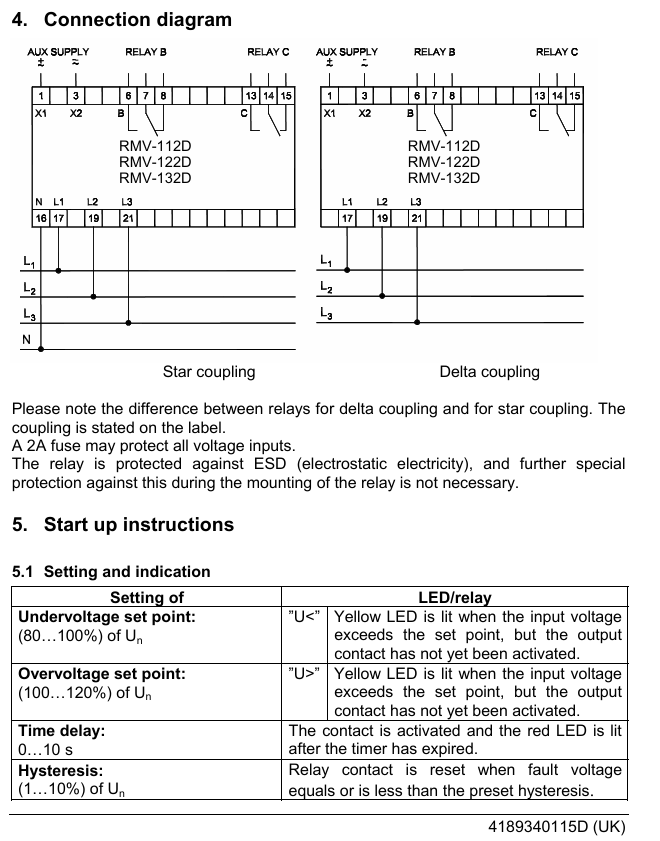
Wiring differences: It is necessary to distinguish between star (STAR) and delta (DELTA) wiring methods. The specific wiring method should be marked on the product label, and refer to the “Connection diagram” for operation.
Voltage protection: All voltage input terminals can be connected in series with 2A fuses to prevent overcurrent damage.
Static protection: The relay comes with ESD (electrostatic discharge) protection, and no additional anti-static measures are required during installation.
Startup and parameter settings
1. Core parameter setting and indication
Set key parameters through the front knob of the relay and provide feedback on the status with LED lights. The specific correspondence is as follows:
Range of parameter settings: LED/relay action feedback
When the input voltage is lower than the set value (U<) and the rated voltage (U ₙ) is 80%~100%, the corresponding yellow LED will light up (the contact is not activated at this time); After the delay is over, the contact will activate and the red LED will light up
When the input voltage is higher than the set value, the yellow LED of “U>” will light up (at this time, the contact is not activated) when the overvoltage setting value (U>) is 100%~120% of the rated voltage (U ₙ); After the delay is over, the contact will activate and the red LED will light up
After a delay of 0-10s, the relay contacts will activate and the red LED will light up
Hysteresis: 1%~10% of the rated voltage (U ₙ) of the hysteresis value is shared by undervoltage/overvoltage. When the fault voltage drops/rises to within the hysteresis value, the relay contacts reset
2. Set examples (to help understand)
Assuming rated voltage range (U ₙ): 95~105V
Undervoltage setting value: 90% of U ₙ (i.e. 90V)
Overvoltage setting value: 110% of U ₙ (i.e. 110V)
Return difference: 5% of U ₙ (i.e. 5V)
The relay is activated when the voltage is ≤ 90V (under voltage) or ≥ 110V (over voltage); When the voltage returns to the range of 95-105V, the contacts reset.
3. Accuracy Description
Front knob setting accuracy: usually ± 10% of the scale, corresponding to ± 2% of the rated voltage (U ₙ).
Higher precision requirement: It is necessary to adjust the equipment connected to the relay (such as the generator) until the target set value is reached.
Technical specifications
Category specific parameters
Frequency range 40~45~65~70Hz
Continuous maximum input voltage: 1.2 × U ₙ; 10s short-term maximum input: 2 × U ₙ
Load requirement of 2k Ω/V
Relay contact: 1 transfer switch for each relay; Rated values: AC 250V-8A-2000A, DC 24V-8A-2000W; Maximum voltage: AC 250V, DC 150V
Response time<100ms
Electrical isolation between input and output: 3250V (50Hz), lasting for 1 minute
Auxiliary power consumption 3.5VA (apparent power)/2W (active power)
AVM 234S is a valve actuator with SUT (SAUTER Universal Technology) locator launched by SAUTER. Its core advantages include automatic valve adaptation, precise driving, high energy efficiency, and low operating noise. It is mainly used to control specific series of valves, adapt to multiple control signal types, and meet the precision and stability requirements of valve regulation in industrial scenarios.
Core functions and features
Wide adaptability
It can drive two-way and three-way valves, covering VQD/BQD, VQE/BQE, VUG/BUG, VUS/BUS, VUP, V6R/B6R and other series.
Supports multiple controller output signals: continuous signal (0… 10 V or 4… 20 mA), switch signal (2-point or 3-point control).
Intelligent regulation and memory function
Equipped with a stepper motor and electronic control unit, it can achieve force controlled power-off to avoid overload damage.
Automatic detection of control signal type (continuous/on/off), displayed through 2 LED indicator lights; Automatic adaptation of valve stroke (minimum 8 mm, maximum 49 mm), measuring stroke without loss after power failure.
The flow characteristics (linear/quadratic/equal percentage) and operating time can be selected through coding switches, and the operating direction can be selected through wiring terminals.
Convenient operation and installation
Patent automatic connection system: After connecting the control voltage, the valve stem automatically connects and is easy to install; Equipped with an external manual adjustment crank, the motor is powered off when deployed, automatically returns to the target position after retraction, and can also trigger reinitialization.
Supports multiple installation methods (vertical to horizontal), provides multiple adapters, and can adapt to non SAUTER valves; There are 3 pre slotted cable entrances (2 M20 × 1.5, 1 M16 × 1.5) with a maximum wiring cross-sectional area of 2.5 mm ².
Durability and power supply
Maintenance free sintered steel gearbox, steel gearbox base plate, stainless steel mounting column, cast light alloy mounting bracket, with a two-part yellow structure, protection level IP66 (EN 60529), protection category III (IEC 60730).
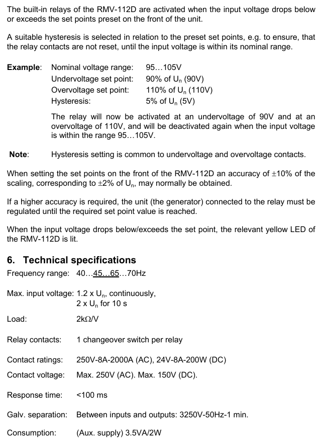
Flexible power supply: 230 V (with module) or direct 24 V~/24 V=, 230 V can be continuously driven, power consumption varies under different power supplies (24 V~/24 V=10 W/20 VA); 230 V with accessories for 13 W/28 VA).
Running performance and running time: 2/4/6 s/mm; Driving force: 2500 N; actuator stroke: 0… 49 mm; 3-point control response time: 200 ms
Signal specifications control signal 1: 0… 10 V, input resistance>100 k Ω; control signal 2: 4… 20 mA, input resistance 50 Ω; Position feedback signal: 0… 10 V, load>2.5 k Ω; starting voltage U0:0 or 10 V; control span Δ U: 10 V; Switching range Xsh: 300 mV
Physical specification weight: 4.1 kg; compliant with EMC Directive 2014/30/EU (EN 61000-6-2, EN 61000-6-4) and Low Voltage Directive 2014/35/EU (EN 60730-1, EN 60730-2-14)
Product model and accessories
main models
AVM234SF132: Valve actuator with SUT locator.
AVM234SF132-5:24 V~Positioner actuator, suitable for V6 */B6 * valves with DN 15… 50.
Core accessories
|Accessory Type | Model and Function|
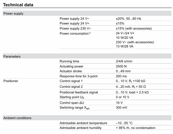
|Voltage divider unit | 0313529001: used for adjusting sequence, installed in an independent junction box, can add 2-point/3-point and continuous drive modules, with an additional power consumption of 2 VA|
|Power supply module | 0372332001:230 V ± 15% power supply; 0372332002:100 V ± 15% power supply|
|Potentiometer | 0372334001 (2000 Ω, 1 W, 24 V), 0372334002 (130 Ω, 1 W, 24 V), 037233406 (1000 Ω, 1 W, 24 V), of which 130 Ω is only used as a voltage divider|
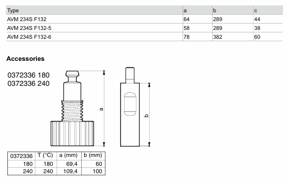
|High temperature adapter | 0372336180: suitable for medium temperatures of 130… 180 ° C; 0372336240: suitable for medium temperatures of 180… 200 ° C|
|Installation and Conversion Kit | 0372338001 (compatible with V/B6 DN 15… 50, V/BXD/V/BXE DN 15… 50, stroke 14 mm), 0372338002 (compatible with V/B6 DN 65… 150, V/BXD/V/BXE DN 65+, stroke 40 mm, no additional adapter required), 0372338003/0372338004 (convert AV24SF132-5/-6 to standard actuator respectively)|
|Non SAUTER Valve Adapter | Compatible with Siemens (0372376010/0372376014), Johnson Controls (0372377001), Honeywell (0372378001/0372378002), ITT Dr ä ger (0372389001/0372389002), Frese (0510390052/0510390053) and other brand valves|
Continuous drive: Connect 0… 10 V/4… 20 mA signals, set the running time through S1/S2, set the flow characteristics through S3/S4, automatically initialize (connect the valve stem to the lower limit of the valve before detecting and saving the stroke at the upper limit), feedback signal corresponds to the effective stroke (0… 10 V corresponds to 0… 100% stroke), no need to reinitialize after power failure.
2-point control (OPEN/CLOSE): Connected by 2 wires at 24 V, terminal 1+2a is powered on, terminal 2b is powered on at 24 V, and the valve stem extends. After power-off, it returns to the opposite terminal position, without feature selection. Terminal 3i/3u/44 is not wired.
3-point control (OPEN/STOP/CLOSE): At 24 V, terminals 2a/2b can be moved to any position when powered on, 1+2b can extend the valve stem when powered on, 1+2a can retract when powered on, and the wiring can be changed to change the direction of travel without feature selection. Terminals 3i/3u/44 are not wired.
230 V/100… 110 V drive: accessory 0372332 is required. The locator works according to the controller output signal. When both 3u (voltage) and 3i (current) signals are present, high values take priority; There are two operating directions (when the signal increases, the 2a power supply valve stem extends and the 2b power supply valve stem retracts), and a partial range can be set for the boost unit.
Initialization and fault handling
Reinitialize: When powered on and there is a continuous signal from 3u/3i, the crankshaft will be unfolded and retracted twice within 4 seconds, the LED will flash red, and the feedback signal during initialization will be 0. The process will be executed with the shortest running time, and the unfolding of the crankshaft can be interrupted. It will take effect after completion.
Jam handling: Upon detecting a jam, attempt to overcome it within 90 seconds. If unsuccessful, set the feedback signal to 0 V. Once overcome, restore normal control.
Meaning of LED indicator light
|LED Status | Meaning|
|Two lights flashing red | Initialization in progress|
|The red light on the upper light is always on | reaching the upper limit or “off” position|
|The red light under the lamp is always on | reaching the lower limit or “open” position|
|The green light on the upper light is flashing | The actuator is running and moving towards the “off” position|
|The green light on the upper light is always on | The actuator stops, and the last running direction was “off”|
|The green light under the lamp is flashing | The actuator is running and moving towards the “open” position|
|The green light under the lamp is always on | The actuator stops, and the last running direction was “open”|
|No light on | No power supply (terminals 2a/2b have no power)|
|Two lights flashing alternately in red and green | The actuator is in manual mode|
Installation and usage precautions
Installation requirements
Prevent condensation and dripping water from entering the actuator along the valve stem; The valve is directly screwed onto the actuator without additional adjustment, and the actuator stem is in the middle position when it leaves the factory.
Outdoor installation requires additional wind and rain protection; Multiple actuators of the same type can be connected in parallel, and the cross-sectional area of the power cord needs to be selected according to the length and quantity of the cable (such as 5 parallel actuators, 50 m cable, recommended 1.5 mm ²).
The actuator can accommodate up to one 230 V module, one auxiliary accessory (auxiliary contact/potentiometer), and one voltage divider unit.
Temperature related requirements
When the temperature of the valve medium is ≤ 110 ° C, the maximum ambient temperature is 60 ° C; when the temperature of the medium is>110 ° C, the maximum ambient temperature is 55 ° C, otherwise a high-temperature adapter (0372336180) needs to be installed.
Corresponding high-temperature adapters are required for medium temperatures of 180 ° C and above, and the actuator column and valve stem may become hot with the increase of medium temperature, requiring attention to protection.
Compliance and Security
Only for the manufacturer’s designated use, modification is prohibited, and relevant product specifications must be followed; If the control unit malfunctions and may cause damage, additional protective measures need to be taken.
Attention should be paid to the rated parameters when using auxiliary contacts. For example, if the gold-plated contact 0372333002 is used once below 10 mA or above 50 V, the gold plating will fail and can only be used in higher rated scenarios.
Disposal
Compliance with current local laws and regulations is required, and material related information can be found in the product’s “Material and Environmental Statement”.
Size specifications
Actuator size (unit: mm)
|Model | a | b | c|
| AVM 234S F132 | 64 | 289 | 44 |
| AVM 234S F132-5 | 58 | 289 | 38 |
| AVM 234S F132-6 | 78 | 382 | 60 |
High temperature adapter size (unit: mm)
|Adapter model | Applicable temperature (° C) | a | b|
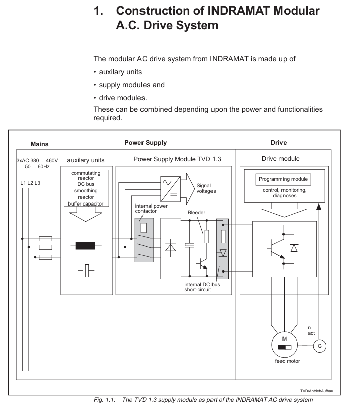
Product positioning: TVD 1.3 is the power module of INDRAMAT modular AC drive system, which is directly connected to the three-phase 380-480V power grid, rectifies the AC power into a stable DC bus voltage (320V DC), supplies power to the drive module, and processes the regenerated electrical energy of the motor to provide control voltage for electronic components.
Core specifications and functional features of the product
1. Key electrical parameters
TVD 1.3 offers two power specifications (7.5kW and 15kW continuous DC bus power), with the core parameters compared as follows:
Parameter category TVD 1.3-08-3 (7.5kW) TVD 1.3-15-3 (15kW) Unit
Input specifications 3 × AC 380-480V (± 10%), 50-60Hz with the same left V/Hz
DC bus voltage of 320 (± 5%) is the same as the left V DC
Continuous DC bus power 7.5 15 kW
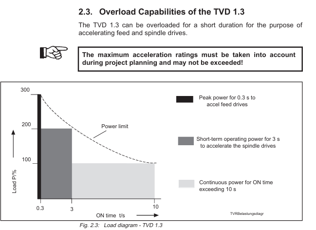
Short time DC bus power (3s, spindle drive acceleration) 15 30 kW
Peak DC bus power (0.3s, feed drive acceleration) 22.5 45 kW
Discharge resistor continuous power 0.5 1 kW
Peak power of discharge resistor 20 40 kW
Maximum regenerative energy 30 60 kW · s
Control voltage output+24V (4.9A), ± 15V (+15V: 2.5-5.1A; -15V: maximum 2A, total ≤ 4A) same as left V/A
Working temperature range: 0-45 ℃ (rated data), -25-55 ℃ (storage and transportation), same as left ℃
Protection level IP 10 (compliant with DIN 40050) same as left-
Weight 10.5 11.2 kg
2. Core functional features
Rectification and voltage stabilization: Rectify three-phase AC power into 320V DC stable DC bus voltage, which can maintain driving dynamic performance even if the grid voltage fluctuates.
Regenerated electrical energy processing: When the motor is in power generation mode, the regenerated electrical energy is converted into thermal energy through internal discharge resistors; External auxiliary release module (TBM 1.2) can be used to enhance processing capacity.
Built in protection mechanism:
Overcurrent protection: When the DC bus is short circuited or overloaded, quickly cut off the output;
Overvoltage protection: When the DC bus voltage exceeds the limit, it triggers a shutdown;
Over temperature protection: When the temperature of the heat sink is too high, a warning should be given first (power off after 30 seconds) to avoid module damage;
Short circuit protection: When the output circuit is short circuited, the internal circuit automatically cuts off the faulty channel without affecting other channels.
Power supply for electronic components: Provide+24V (load voltage) and ± 15V (measurement voltage) for all connected drive modules. In case of power failure, temporary power supply is provided by the DC bus to ensure the functionality of the driving electronic components.
Flexible control and redundancy: supports dynamic braking of DC bus (synchronous motor with short-circuit bus braking in case of fault), and can be configured with external jumper to drive the braking mode after power failure; Support redundant configuration to enhance system reliability.
Electrical Connection and Installation Specification
1. Core connection configuration
TVD 1.3 needs to be used in conjunction with supporting components, and there are two main connection methods:
Compact configuration (including NAM 1.3 module): NAM 1.3 is an integrated power connection module with built-in commutation choke, buffer capacitor, and DC bus smoothing choke to reduce wiring workload. It is compatible with TVD 1.3-08 (with NAM 1.3-08) and TVD 1.3-15 (with NAM 1.3-15).
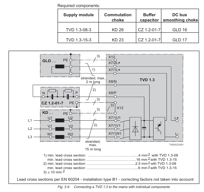
Distributed configuration (independent components): It is necessary to separately connect the commutation choke (KD 26/23), buffer capacitor (CZ 1.2-01-7), and smoothing choke (GLD 16/17), which are suitable for space limited or special working condition scenarios.
2. Key wiring requirements
Main power supply wiring: three-phase 380-480V connected to terminal X7 (1U1/1V1/1W1), with a wire cross-sectional area of ≥ 10mm ² (copper core, rated at 75 ℃), requiring gL type fuses (maximum 35A) or circuit breakers (15A/30A, corresponding to 7.5kW/15kW).
DC bus wiring: Connect the drive module through a bus bar, with a wire cross-sectional area of ≥ 4mm ² (7.5kW) or 10mm ² (15kW), and a maximum wiring distance of 1 meter. Twisted pair cables are required to reduce interference if exceeded.
Control signal wiring: 16 pin bus cable (X1 terminal) is used for communication and power supply of the drive module, and a terminal plug is required to start the high-voltage part; The control terminals (X2/X3/X4/X5) are used for brake control, fault signal output, etc., with a wire cross-sectional area of ≤ 2.5mm ².
3. Installation requirements
Cabinet installation: The module protection level is IP 10 and needs to be installed in a closed cabinet with a temperature of ≤ 45 ℃ and humidity of ≤ 95% (no condensation);
Heat dissipation space: At least 80mm of ventilation space should be reserved above and below the module, and flammable materials (such as cables) should not be placed within 300mm around the discharge resistor;
Grounding specification: It is necessary to connect the cabinet PE guide rail, and the cross-sectional area of the grounding wire should be ≥ 10mm ² (copper core), ensuring that the grounding resistance is ≤ 4 Ω;
Altitude adaptation: When the altitude exceeds 1000 meters, the power usage should be reduced according to the derating curve (such as reducing the power to 80% at 2000 meters).
Troubleshooting and Maintenance
1. Fault diagnosis and localization
The front panel of the module is equipped with LED diagnostic lights, which indicate the type of fault through different colors (green/red/flashing). The core faults and troubleshooting methods are as follows:
Fault type LED indication Possible causes Troubleshooting methods
Control voltage fault (+24V/± 15V)+24V/± 15V, red light, electronic power supply loss, load exceeding upper limit, check main fuse, disconnect bus to detect voltage, reduce load
Drive or power failure Bb1 red light drive module failure, loose bus connection check drive diagnosis, re plug and unplug bus cable, confirm terminal plug installation
Overcurrent fault I-FAULT light red DC bus short circuit, motor cable damage, disconnection of drive connection, detection of bus insulation, replacement of damaged cable or drive
Release overload P-FAULT light red regeneration energy over release capability, increase auxiliary release module (TBM), reduce driving and braking frequency
Overheating fault T-FAULT light red, poor heat dissipation, high ambient temperature. Clean the heat dissipation channel, improve cabinet ventilation, and reduce module load
Overvoltage fault U-FAULT light red grid voltage too high, rectifier circuit fault check grid voltage (≤ 480V ± 10%), replace module
2. Maintenance and replacement standards
Regular maintenance: Check the tightness of the wiring terminals and the cleanliness of the heat sink every 6 months, and measure the insulation resistance (≥ 10M Ω) annually;
Module replacement: After power off, wait for 5 minutes (capacitor discharge), confirm that there is no voltage, remove the wiring, replace with a module of the same model (matching power and version), and test the bus communication and voltage output after rewiring.
Selection and ordering information
1. Core component model
Component category, model, and specification description
Power module TVD 1.3-08-3 7.5kW continuous DC bus power, 320V DC output
TVD 1.3-15-3 15kW continuous DC bus power, 320V DC output
Integrated connection module NAM 1.3-08 compatible with TVD 1.3-08, including commutation choke/buffer capacitor
NAM 1.3-15 is compatible with TVD 1.3-15, including commutation choke/buffer capacitor
The power module should be selected based on the total power of the drive (continuous power should cover the sum of the rated power of all drives);
If the drive frequently starts, stops, or brakes, an additional auxiliary release module (TBM) or DC bus capacitor needs to be configured;
High altitude (>1000 meters) or high temperature (>40 ℃) environments require the selection of downgraded models or strengthened heat dissipation measures.
Safety and Compliance Instructions
Hazardous Area Use: Only applicable to Class I, Zone 2 hazardous environments (non flammable areas), prohibited for use in explosive environments;
Voltage safety: There is a maximum of 450V DC high voltage inside the module. After power failure, it is necessary to wait for 5 minutes for discharge, and only certified electricians are allowed to operate;
Compliance standards: comply with UL standards, DIN 40050 (protection level), EN 60204 (electrical installation) and other specifications, and confirm the compatibility with local electrical regulations before use.
Document ID: EP03-490-520, Release 520, Version 1.5
Scope of application: Expert Series-C I/O modules and C300 controllers, supported since the Expert R300 version
Core component definition:
IOTA (Input Output Termination Assembly): A component that integrates I/O module fixation and on-site wiring functions. The module is directly plugged into IOTA without the need for an additional chassis
IOM (Input Output Module): A module equipped with core electronic components to achieve specific I/O functions and obtain power from IOTA
Core functions and design highlights
1. Universal design advantages
Compact integrated architecture: IOM and field terminals are integrated into IOTA, eliminating the need for independent electronic component chassis, significantly reducing device size, and improving cabinet space utilization
Convenient wiring and maintenance: using two-level “separable” terminals, convenient for on-site wiring installation and later maintenance; Supports up to 12AWG (2.5mm ²) multi strand wire access
Simplified power supply and redundancy: The on-site power supply is provided through IOTA, eliminating the need for additional power and manual wiring; Redundant configuration only requires adding a second IOM on IOTA, without the need for external cables or control devices
Efficient heat dissipation and layout:
Vertical installation design: Suitable for scenarios where on-site wiring is connected from the top/bottom of the cabinet
Tilted structure: optimizes air circulation inside the cabinet, improves heat dissipation efficiency, and adapts to high-density installation requirements
Information Ring “Identification: Quickly guide maintenance personnel to view equipment status information
Built in protection mechanism: Input/output circuits have short-circuit protection, no need to connect fuses in series, reducing installation and maintenance costs
2. IOTA multifunctional integration
IOTA serves as the core carrier, integrating multiple functions and reducing external component dependencies
Support switching between single module and redundant module configurations
Built in process signal termination and signal conditioning functions
Directly connect to networks such as FTE, I/O LINK, etc
Realize on-site power distribution without the need for external wiring grouping
Provide stable power supply for the inserted IOM
Module Classification and Key Specifications
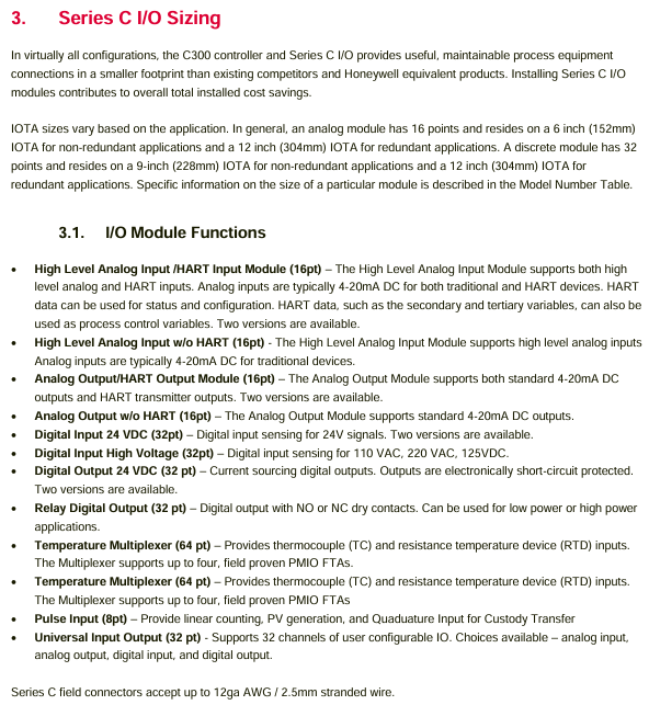
The Series-C I/O module covers 8 major categories of signal processing requirements, with different modules focusing on parameters such as channel quantity, input/output range, and accuracy. The core classifications and representative module specifications are as follows:
1. Analog input module (AI)
Mainly used to receive current/voltage signals from transmitters or sensors, with some supporting the HART protocol for device configuration and status monitoring.
CC-PAIH01/02 with HART protocol 16 current (4-20mA), voltage (0-5V/1-5V/0.4-2V) 12 single ended+4 differential channels, supports open circuit detection, Class 1 Div 2 non flammable power supply
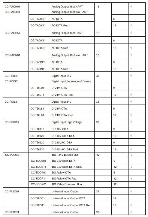
CC-PAIH51 with HART protocol 16 current only (4-20mA, 200 Ω load) full single ended channel, no voltage/differential input, supports HART device configuration
CC-PAIX01/02 does not have HART protocol. The current (4-20mA) and voltage (0-5V/1-5V/0.4-2V) are consistent with the parameters of CC-PAIH01/02 and do not have HART function
CC-PAIN01 without HART protocol 16 only current (4-20mA, 200 Ω load) full single ended channel, non flammable power supply, suitable for basic current signal acquisition
2. Temperature input module
Specially designed for thermocouples (TC) and thermistors (RTD), supporting low-temperature drift and high-precision temperature measurement.
Module model, core function, number of channels, support for sensor types, key characteristics
CC-PAIM01 (LLMUX) temperature multiplexing 64 (16 channels/FTU) TC (J/K/E/T/B/S/R, etc.), RTD (Pt100/Ni120/Cu10) need to be matched with PMIO FTA, support remote cold end compensation, 1-second scanning cycle
CC-PAIL51 low-level temperature input 16 TC/RTD (configurable per channel) directly integrated into Series-C IOTA, no external FTA required, operating temperature from -40 to+70 ℃
3. Pulse Input Module (PI)
Used for processing pulse generation equipment signals, suitable for measurement and trade handover scenarios, supporting high-precision frequency and cycle measurements.
Module model CC-PPIX01
Number of channels: 8 single channels/4 dual channels (can be mixed configuration)
Frequency range: Single channel 0-100kHz, dual channel 0-10kHz
Accuracy within the range of 0.5Hz-100kHz, ± 0.001% reading error
Key features support MeterSuite trade handover application, compliant with ISO 6551 standard, with “quick cut-off” function (1ms delay)
4. Analog Output Module (AO)
Output stable current signals to actuators and recorders, with partial support for HART protocol and configurable fault safety status.
CC-PAOH01/51 with HART protocol 16 4-20mA support FAILOPT (maintain last value/switch to safe value), open circuit detection, accuracy ± 0.35% of full range at 25 ℃
CC-PAOX01/PAON01 without HART protocol 16 4-20mA and with HART module parameters consistent, without HART communication function, maximum load 800 Ω (24V power supply)
5. Digital Input Module (DI)
Receive discrete voltage signals, adapt to different voltage levels, and partially support sequence of events (SOE) recording.
Module model, voltage level, channel number, key characteristics
CC-PDIL01/51 24VDC 32 CC-PDIL01 supports open circuit detection and isolation voltage of 1500VAC; CC-PDIL51 has no open circuit detection and is isolated from 1000VAC
CC-PBIS01 24VDC 32 supports SOE (1ms resolution), three scanning modes (normal 20ms/fast 5ms/SOE mode)
CC-PDIH01 high voltage (110VAC/220VAC/125VDC) 32 is compatible with different high voltage signals, and can switch voltage types by replacing IOTA, reducing the variety of spare parts
6. Digital Output Module (DO)
Output discrete signals to control external devices (such as solenoid valves, intermediate relays), with short-circuit protection and fault safety configuration.
Module model, output type, number of channels, key characteristics
CC-PDOB01 24VDC bus type (source output) 32 no fuse short circuit protection, supports FAILOPT, maximum 0.5A per channel, maximum 6A per module
CC-PDOB01 (relay IOTA) dry contact (NO/NC configurable) 32 with CC-TDOR01/11 IOTA, maximum contact 250VAC/125VDC, mechanical life 5 million times
CC-PDOD51 24VDC current output with 32 coating protection, maximum 0.1A per channel, isolation voltage 1000VAC
7. Universal Input/Output Module (UIO)
Single module supports multiple types of signal configurations, with high flexibility and adaptability to complex mixed signal scenarios.
CC-PUIO01 32 AI/AO/DI/DO/pulse input (15-18 channels) supports HART 7, -40 to+70 ℃ working temperature, electronic short circuit protection
CC-PUIO31 32 AI/AO/DI/DO/SOE/pulse input (any 4-channel) HART channel independent modem, SOE 1ms resolution, pulse frequency 0-15kHz
IOTA size and compatibility configuration
The size of IOTA varies with module type (analog/digital) and redundancy requirements. Non redundant configurations have smaller sizes, while redundant configurations require longer IOTA. The specific adaptation relationship is as follows (excerpt from core combinations):
IOM type non redundant IOTA model non redundant size (inches) redundant IOTA model redundant size (inches) number of channels
Analog Input (AI) CC-TAIX01 6 CC-TAIX11 12 16
Temperature input (LLMUX) CC-TAIM01 6-64 (FTA required)
Module positioning: IOM needs to be plugged into the corresponding IOTA, which is fixed to the 24VDC bus power supply rail of the cabinet with screws
Wiring specifications:
Wire specifications: It is recommended to use copper wire with a rated temperature of 75 ℃, and a single terminal can support 2 wires of the same specification or 1 maximum 12AWG wire
Stripping length: Unified at 0.25 inches (7mm), excessive length may result in exposed wires and pose a risk of electric shock
Noise protection: Ensure that the module installation screws are tightened and grounded according to specifications; The noise reduction gasket on the right side of the module (both sides of the power module) should be in contact with adjacent modules/cabinets to avoid electromagnetic noise interference
2. Installation requirements for hazardous areas
For Class I Zone 2 hazardous environments, the following regulations must be followed:
Only applicable to Class I Zone 2 A/B/C/D hazardous areas or non hazardous areas, and cannot be used for other hazardous level scenarios
It is prohibited to replace module components, otherwise it may damage the explosion-proof applicability
Before power outage or confirming the safety of the area, it is forbidden to disconnect the equipment connection to avoid the risk of explosion
Ordering Information (Core Components)
In addition to the IOM module, matching IOTA and fan components need to be selected based on the number of cabinet slots and power supply type. Some key models are as follows:
Product Description Model
16 channel with HART analog input module CC-PAIH01
32 channel 24VDC digital input module CC-PDIL01
32 channel 24VDC bus type digital output module CC-PDOB01
Environmental specifications: The temperature and humidity tolerance, vibration and impact and other environmental parameters of the module should refer to the “Series-C Platform Specifications” and technical document EP03-520-xxx
Compliance certification: FCC, EU directives and other compliance information, please refer to Appendix A of the “Expert RX7i Installation Manual” (GFK-2223)
Maintenance suggestion: Regularly check the tightness of IOTA terminal wiring, module temperature, and LED status. In case of faults, prioritize using the “information ring” and LED to determine the type of problem (such as open circuit, short circuit, overheating)
Both modules are dedicated power supplies for slot 0 of the RX7i mainframe, providing three output voltages and logic level timing signals:+5VDC,+12VDC, and -12VDC. The core differences are concentrated in power, heat dissipation requirements, and current output capabilities. The specific parameters are shown in the table below:
Parameter IC698PSA100 IC698PSA350
Total output power 100W 350W
Cooling requirements: No forced air cooling is required in an environment of 0-60 ℃ (natural convection is sufficient). In an environment of 0-60 ℃, forced air cooling (70CFM air volume) is required for the bottom fan tray of the rack. If there is no forced air cooling, it should be operated according to the temperature derating curve
Output current+5VDC: maximum 20A;+12VDC: maximum 2A; -12VDC: maximum 1A+5VDC: maximum 60A;+12VDC: maximum 12A; -12VDC: maximum 4A
Input voltage range 85-264VAC (47-63Hz), 100-150VDC, same as IC698PSA100
Typical input power is 125W, maximum 150W, typical 437W, maximum 500W
Input surge current 115VAC cold start: maximum 15A; 230VAC cold start: maximum 30A, continuous 100ms 115VAC cold start: maximum 30A; 230VAC cold start: maximum 60A, continuous 100ms
Fuse specifications 4A/250V (5 × 20mm, B and subsequent versions) 8A/250V (5 × 20mm, B and subsequent versions)
Key functions and protection mechanisms
1. General functions
Wide voltage adaptation: Supports 85-264VAC AC input and 100-150VDC DC input, suitable for different power supply scenarios.
Power factor correction: When operating in AC mode, the power factor should be ≥ 0.99 (effective within the range of 90-260VAC) to improve the efficiency of energy utilization.
Continuous power supply during power outage: When the AC input is interrupted, the module can maintain the output power for one AC line cycle to avoid output interruption; The ACFAIL # signal will trigger at least 5ms before the output falls below the specification limit, providing a power outage warning to the system.
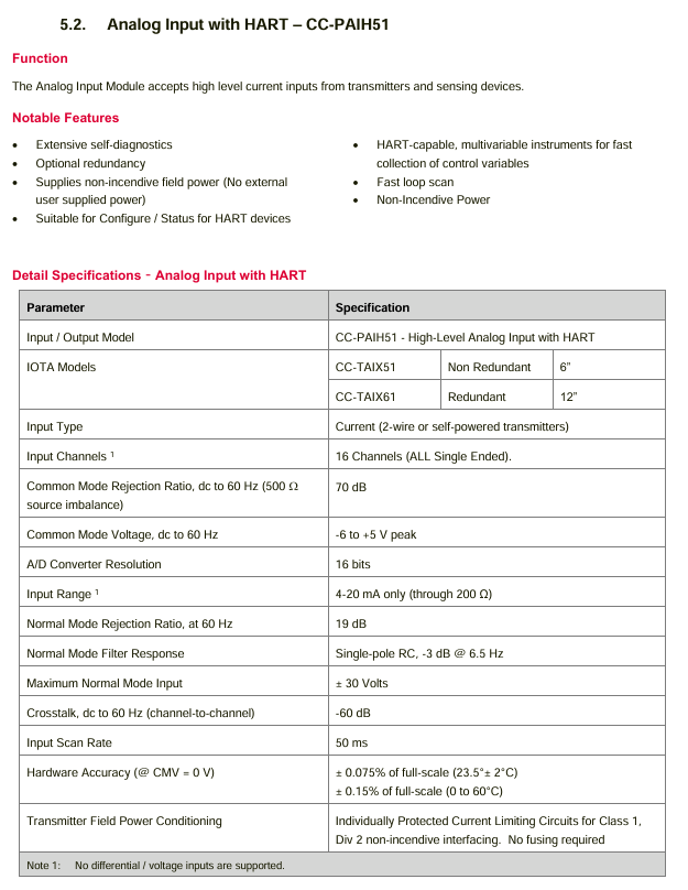
LED status indicator: The front panel is equipped with 3 LEDs, each displaying different statuses:
Field OK (green): It lights up when the AC power input is within the specification range;
OUTPUT OK (green): It lights up when all three DC output channels are working normally, and turns off when any channel fails;
OVER TEMP (red, IC698PSA350 only): Illuminates when the power supply temperature exceeds the critical value or when the airflow sensor detects a disconnection.
2. Protection mechanism
Overvoltage protection: When the voltage of any output channel exceeds 15% or more of the nominal value, all outputs will be locked and closed, and the power switch needs to be restarted or the AC input disconnected to restore.
Overcurrent/Short Circuit Protection: All three output channels have electronic current limiting function. When overloaded or short circuited, the voltage will drop (which may cause the voltage of other channels to drop synchronously). After the fault is removed, it will automatically recover (with reserved component cooling time).
Over temperature protection: Equipped with a built-in temperature sensor, the output channel is closed when overheating occurs, and the temperature automatically recovers when it drops to the normal range; The IC698PSA350 is additionally equipped with an airflow sensor that locks the output when a fan fault or airflow blockage is detected, and recovers after the temperature drops (the airflow sensor can be enabled/disabled through a jumper, default enabled, with 1-2 pins enabled and 2-3 pins disabled).
Input protection: Both the live and neutral wires of the AC input are equipped with replaceable fuses to prevent abnormal input from damaging the module.
Version iteration and compatibility
Functional compatibility: The E version (released in August 2010) is completely interchangeable with all older versions (A/B/C/D), with no differences in functionality or performance, only label updates.
Version critical update:
Version A (May 2003): Initial release version;
Version B (May 2004): No clear feature updates, please refer to GFK-2237B for details;
Version C (June 2005): Added over temperature detection function, please refer to GFK-2237C for details;
D version (August 2006): Complies with ATEX explosion-proof directive (Class II, Class 3 hazardous area), fixes occasional issues of CPU memory damage caused by power shutdown;
Version E (August 2010): Only updated tags, no functional changes.
Installation and safety regulations
1. Installation requirements
Installation position: Can only be installed in the leftmost slot (slot 0) of the RX7i standard rack;
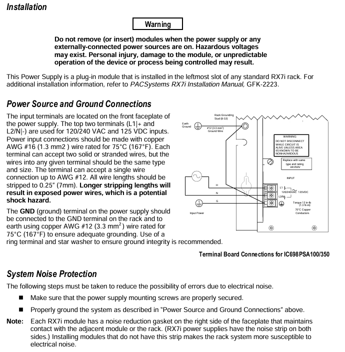
Wiring specifications:
Input wiring: Use 75 ℃ – rated 16AWG (1.3mm ²) copper wire, and the terminal can be connected to 2 wires of the same type/specification. A single wire can support up to 12AWG, and the wire stripping length is 0.25 inches (7mm). If it is too long, the wire will be exposed and there is a risk of electric shock;
Grounding requirements: The power GND terminal needs to be connected to the rack GND terminal and ground with a 75 ℃ – rated 12AWG (3.3mm ²) copper wire. It is recommended to use a ring terminal and star washer to ensure reliable grounding, with a wiring torque of 12 inch pounds (1.3N · m);
Noise protection: Ensure that the power supply installation screws are tightened and grounded according to specifications; The RX7i power module has noise reduction pads on both sides, which need to be in contact with adjacent modules/racks. Modules without pads will increase the sensitivity of the system to electromagnetic noise.
2. Safety Warning
When the input power is turned on, there is a lethal voltage inside the module. It is forbidden to plug and unplug the module with power on, otherwise it may cause personal injury, module damage, or system loss of control;
When used in Class I Zone 2 hazardous environments, it is necessary to comply with: only applicable to Class I Zone 2 A/B/C/D hazardous areas or non hazardous areas; Prohibit replacing components (which may affect explosion-proof applicability); It is prohibited to disconnect equipment before power outage or confirming the safety of the area.
Order Information
In addition to the power module, the matching fan tray should be selected according to the rack specifications and power supply type. The specific models are as follows:
Product Description Product Model
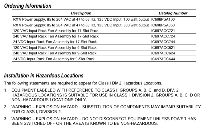
RX7i 100W power module (85-264VAC/100-150VDC input) IC698PSA100
RX7i 350W power module (85-264VAC/100-150VDC input) IC698PSA350
17 slot rack 120VAC input fan component IC697ACC721
17 slot rack 240VAC input fan assembly IC697ACC724
17 slot rack 24VDC input fan component IC697ACC744
9-slot rack 120VAC input fan component IC697ACC621
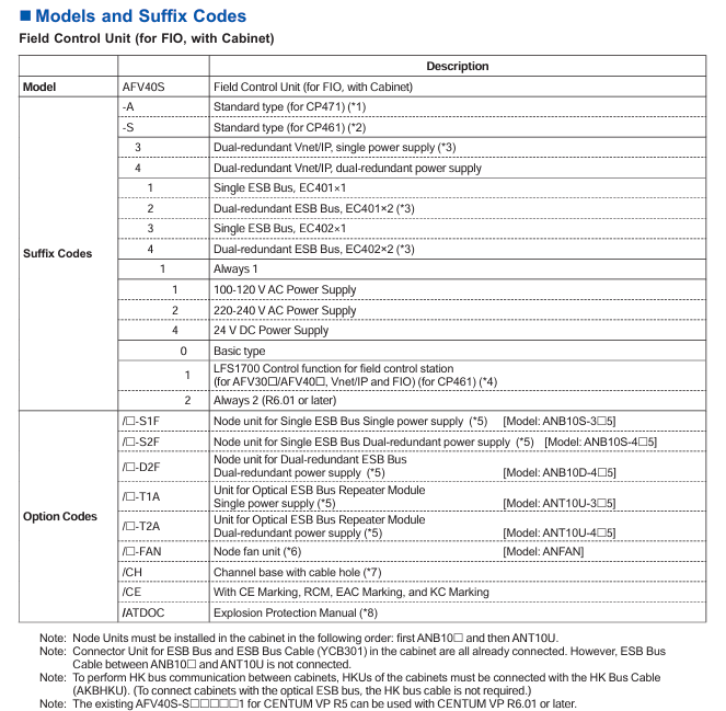
Core role: AFV40S/AFV40D is the core component of the CENTUM VP Field Control Station (FCS), responsible for “field signal acquisition, control logic operation, equipment linkage control” functions, adapted to FIO (Field Input/Output) systems, supports remote I/O node expansion, and is widely used in process industries such as petrochemicals, power, and pharmaceuticals.
Differentiated design: AFV40S is a single configuration unit suitable for non safety critical scenarios; AFV40D is a dual redundant configuration (with redundant power supply, processor, and communication bus), suitable for critical control circuits that require extremely high reliability, such as reactor temperature control and emergency shutdown systems.
Core technical specifications
(1) General basic parameters
Power outage data protection
The main memory is equipped with battery backup, with a maximum power-off protection time of 72 hours and a battery charging time of at least 48 hours, ensuring that control programs and configuration parameters are not lost after power failure and do not need to be reloaded after re powering on.
READY contact output: 3 terminals (NC normally closed, NO normally open, C common terminal), switch contact state in case of FCU fault (such as NC opening and NO closing in case of fault), contact rated parameters: maximum 250V AC/30V DC voltage, 2A current, 125VA power, can be connected to external alarm or monitoring equipment.
communication interface
Vnet/IP interface: Dual redundancy design (AFV40S can provide single/dual power supply, AFV40D requires dual redundancy), used for communication with the operator station (HIS) and other control units of the CENTUM VP system, in compliance with industrial Ethernet standards, ensuring reliable data transmission.
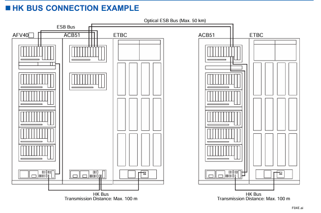
ESB bus interface: AFV40S supports single configuration or dual redundancy, AFV40D enforces dual redundancy and is used to connect FIO node units (ANB10 series) or optical ESB bus relay modules (ANT401/ANT411), expanding on-site I/O access capabilities.
Environmental monitoring (HK function)
Built in HKU (House Keeping Unit) monitors the environmental status of the connected cabinet (such as temperature and fan operation status) through the HK bus or optical ESB bus, and displays the HKU operation status on the HIS (Human Machine Interface), supporting system alarm output.
HK bus parameters: Supports connecting HKUs to cabinets such as ACUKT1/ACUKT2/ACB51/XLCabinet, with a maximum of 9 cabinets connected to a single FCU. The total length of the HK bus cable (AKBHKU) is up to 100 meters (daisy chain connection).
(2) Equipment configuration inside the cabinet
Standard equipment
Each FCU cabinet includes: 1 FCU, 1 distribution board with built-in HKU (supporting single/dual power), 2 vertical power bus units (AEPV7D, 1 front and 1 rear), up to 4 node fan units (ANFAN, 2 front and 2 rear, depending on the number of nodes), and 4 cabinet door fan units (AIP601, 2 front and 2 rear cabinet doors).
FCU module configuration
Power module: Supports PW481/PW482/PW484, dual redundant configuration requires 2 modules of the same model to ensure seamless switching in case of power failure.
Processor module: Supports CP471 (CENTUM VP R6.05 and above) or CP461 (default standard), dual redundancy configuration requires 2 modules of the same model, and only authorized engineers from Yokogawa can perform the replacement of CP461 to CP471.
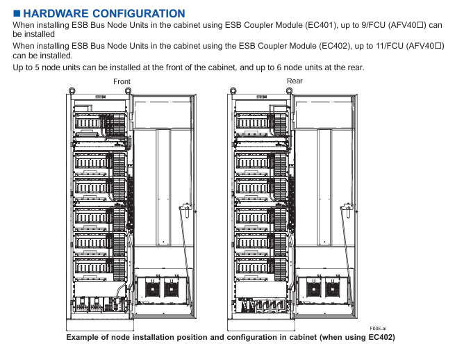
ESB bus coupler module: Supports EC401 (single/dual redundancy) or EC402 (single/dual redundancy), with two identical modules required for dual redundancy configuration to expand ESB bus nodes (EC401 supports up to 9 nodes, EC402 supports up to 11 nodes).
I/O module: Supports up to 6 non-standard I/O modules, which need to be selected according to the type of on-site signal (such as analog input, digital output) and adapted to the FIO system.
(3) Power supply and power consumption
Description of parameters AFV40S/AFV40D (maximum node configuration)
The supply voltage of 100-120V AC/220-240V AC (50/60Hz) and 24V DC should be specified through suffix codes, such as “1” representing 100-120V AC and “4” representing 24V DC
Maximum power consumption (100-120V AC) 2500VA node unit power consumption at full configuration, reduced power consumption in single node configuration
Maximum power consumption (220-240V AC) 2860VA-
Maximum power consumption (24V DC) 71A-
Power protection dual power redundancy (AFV40D mandatory, AFV40S optional) The distribution board supports dual power input and automatically switches in case of failure
(4) Mechanical and environmental parameters
Cabinet size and weight
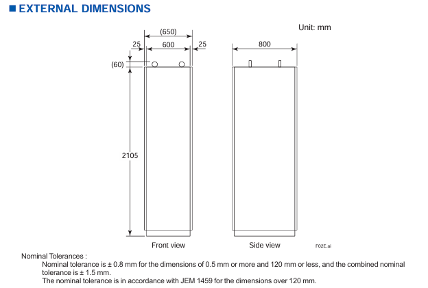
Dimensions (width x depth x height): approximately 600mm x 800mm x 2105mm (including cabinet), with dimensional tolerances in accordance with the JEM 1459 standard (± 0.8mm below 120mm, standard tolerances above 120mm).
Weight: The empty cabinet weighs about 240kg, and the maximum node configuration (11 node units) is about 360kg. During installation, it is necessary to ensure that the load-bearing bracket of the cabinet meets the load requirements.
environmental adaptability
Working temperature: -10 ℃~+50 ℃ (depending on the cabinet door fan and node fan for heat dissipation); Storage temperature: -20 ℃~+60 ℃.
Protection level: IP20 (only applicable to internal components of the cabinet, must be installed in a closed cabinet to avoid direct contact with dust and liquids).
Anti interference: Compliant with industrial electromagnetic compatibility (EMC) standards, refer to the CENTUM VP system overview document (GS33J01A10-01EN) for details.
Installation restrictions and configuration requirements
(1) Node unit expansion restrictions
Number and type of nodes
A single FCU can support up to 13 node units, including ESB bus node units (ANB10 series) and optical ESB bus relay module units (ANT10U), and can install up to 11 units in the cabinet (5 in the front and 6 in the back).
Remote node expansion: It needs to be connected through the optical ESB bus relay main module (ANT401/ANT411), and the relay module needs to be installed in slots 1-6 of the FCU (dual redundant configuration needs to be installed in pairs, single configuration needs to be installed in the order of slots 1, 3, and 5). The maximum transmission distance of the optical fiber cable is 50km.
Fan unit selection rules
The number of node fan units (ANFAN) should be determined based on the total number of node units in the cabinet to ensure sufficient heat dissipation and avoid module overheating
Number of required node fan units for the total number of node units (ANB10+ANT10U) in the cabinet
0-4 1
5-9 2
10 3
11 4
(2) Hardware Installation Specification
Cabinet grounding and wiring
Power wiring: M6 screw terminals are used, supporting dual power systems (main/backup power needs to be distinguished), and the input voltage should be consistent with the suffix code (such as 100-120V AC or 24V DC).
Grounding requirements: Use M8 screw terminals, with a protective grounding (PE) resistance of ≤ 4 Ω, to ensure the safety of personnel and equipment in case of leakage.
READY contact wiring: M4 screw terminals are used, and NC/NO contacts need to be selected according to the requirements of external alarm devices.
Module installation sequence
The node units inside the cabinet need to be installed in the order of “ANB10 series (ESB bus nodes) first, then ANT10U (optical ESB relay units)” to avoid communication conflicts.
The dual redundant modules (power supply, processor, ESB coupler) need to be installed in adjacent slots to ensure synchronization of redundant switching signals.
Cable restrictions
HK bus cable (AKBHKU): total length ≤ 100 meters. When connecting multiple cabinets in a daisy chain, the length of each cable segment needs to be included in the total length.
ESB bus cable (YCB301): The pre wiring inside the cabinet has been completed, but the cable between ANB10 and ANT10U needs to be connected on site, and parallel laying with power cables should be avoided (spacing ≥ 300mm) to reduce electromagnetic interference.
5 (power type) 1/2/4 1=100-120V AC; 2=220-240V AC; 4=24V DC
Option code (optional as needed):
/ – S1F: Single ESB bus node unit (single power supply, model ANB10S-3 5), is the number of units (1-9/A=10/B=11).
/ – FAN: Node Fan Unit (ANFAN), is the number of fans (1-4, determined by the total number of nodes).
/CH: Channel base with cable holes (rear 300 × 40mm hole, factory equipped with filling plate), but CE/RCM/EMC/KC certification cannot be selected at the same time after selecting this option.
/ATDOC: Includes explosion-proof manual (compliant with ATEX directive, applicable to potentially explosive environments).
(2) AFV40D (Dual Redundant Field Control Unit) Model Code
Model format: AFV40D – [suffix code 1] [suffix code 2] [suffix code 3] [suffix code 4] [suffix code 5] [suffix code 6] [suffix code 7]+Option code Core difference: AFV40D requires dual redundancy configuration, suffix code 2 is fixed as “4” (dual redundant Vnet/IP+dual power supply), suffix code 3 is fixed as “2/4” (dual redundant ESB bus), and option code only supports dual redundant node units (such as/ – D2F, dual redundant ESB node units).
Software requirements and compatible systems
software license
AFV40S/AFV40D require separate purchase of software license, core dependencies:
VP6F1700 Field Control Station Control Function License (GS33J15C10-01EN): Supports the control logic operation of CP461/CP471 processors.
VP6F3100 Project I/O License (GS33J15A10-01EN): Supports I/O node expansion and signal acquisition for FIO systems.
Event Sequence Manager (SEM) compatibility
If SEM functions (event collection, timestamp recording) are required, hardware conditions must be met (such as supporting high-precision time synchronization), please refer to the document “GS33J30D10-01EN” for details.
system compatibility
Only compatible with Yokogawa CENTUM VP integrated production control system, supporting R6.01 and above versions, with CP471 processor requiring R6.05 and above versions; Seamless integration with FIO system, optical ESB bus relay module (ANT401/ANT411), HKU compatible cabinet (ACUKT1, etc.).
Attachments and related products
Standard Appendix
Factory standard: Cabinet door filter (model T9070CB, quantity 2), used to filter the dust in the cabinet inlet air, needs to be replaced regularly to ensure heat dissipation effect.
Related Products
Cabinet Connection Kit: AKT211, used for HK bus or power connection between multiple AFV40 cabinets.
Cabinet side panel: ACB2P, 2 pieces per cabinet (1 on each side) are required for cabinet side protection and need to be ordered separately.
ESB bus cable: YCB301, pre wired in the cabinet already included, additional configuration is required for the connection between ANB10 and ANT10U.
Key application precautions
Effectiveness of redundant configuration
The dual redundancy function of AFV40D must ensure that the “power supply, processor, and ESB bus module” are all of the same model and installed in designated redundancy slots, otherwise automatic fault switching cannot be achieved.
Explosion proof environment use
If used in potentially explosive environments (such as Zone 2), select the/ATDOC option code, obtain the explosion-proof manual, and ensure that the cabinet and node units comply with ATEX/IECEX certification requirements.
Maintenance and replacement
The replacement of processor modules (CP461 → CP471) is only allowed to be operated by authorized engineers from Yokogawa. User initiated replacement will result in the warranty being invalidated; The battery needs to be replaced every 3-5 years to avoid data loss during power outages.
Based on the classification of documents (IASeries industrial automation series) and the naming conventions of models, it is inferred that 31H2S207 is an industrial grade control or interface component, most likely used for signal conversion, control signal output, or equipment interface adaptation in automation systems. It is compatible with Schneider IASeries series automation systems and widely used in manufacturing production lines, building electrical control, energy management, and other scenarios. Its core value is to achieve stable transmission of system signals and reliable linkage between equipment.
Core technical parameters
(1) Electrical characteristics
The document provides a detailed list of the electrical parameters of the product to ensure its compatibility with the voltage and current environment of industrial sites. The key parameters are as follows:
Power parameters
Rated power supply voltage: Supports 110-240V AC wide voltage input (50/60Hz universal frequency), adapts to industrial power grid standards in different regions, and avoids equipment failures caused by voltage fluctuations.
Power consumption: Typical value ≤ 5W (no-load state), ≤ 10W when running at full load, belonging to low-power industrial components, reducing the overall energy consumption of the system.
Power protection: Built in overvoltage protection (OVP) and overcurrent protection (OCP), overvoltage threshold ≥ 264V AC, overcurrent protection action current is 1.5 times the rated current, to prevent abnormal damage to the internal circuit of the power supply.
Signal input/output parameters
Input signal type: Supports dry contact signals (passive) and wet contact signals (active, such as 24V DC), suitable for industrial field sensors (such as limit switches, proximity switches) or controller output signals, input impedance ≥ 10k Ω, to avoid signal attenuation.
Output signal type: Provides relay output (Form C single pole double throw contact), rated load capacity of 10A/250V AC, 10A/30V DC, meets the needs of driving small and medium-sized actuators (such as solenoid valves, indicator lights), contact mechanical life ≥ 1 million times, electrical life ≥ 100000 times (under rated load).
Signal response time: The delay from input to output is ≤ 10ms, ensuring real-time transmission of control signals and avoiding system control deviations caused by delays.
Insulation and anti-interference characteristics
Insulation resistance: The insulation resistance between the input/output circuit and the power circuit is ≥ 100M Ω (measured by a 500V DC megohmmeter) to prevent signal interference or equipment damage caused by leakage between circuits.
Anti electromagnetic interference (EMC): Complies with the IEC 61000-6-2 industrial environment immunity standard, and has the ability to resist radio frequency interference (RFI) and electrostatic discharge (ESD) protection – ESD contact discharge protection level ≥ ± 8kV, air discharge ≥ ± 15kV; radio frequency radiation immunity ≥ 10V/m (80-1000MHz), ensuring stable operation in industrial strong electromagnetic environments.
(2) Mechanical characteristics
Appearance and Installation
Dimensions: Designed with standard DIN rail installation, the dimensions are approximately 17.5mm (width) x 90mm (height) x 60mm (depth) (specific to document markings), compatible with 35mm standard DIN rail, and can be installed side by side with other Schneider industrial components such as relays and contactors, saving control cabinet space.
Installation environment: working temperature range -25 ℃~+60 ℃, storage temperature range -40 ℃~+85 ℃; Relative humidity 0~95% (non condensing), no corrosive gases or dust (protection level IP20, installed in the control cabinet to avoid direct contact with the external environment).
structural design
Shell material: Made of flame-retardant ABS plastic (UL94 V-0 flame retardant rating), it has good high temperature resistance and fire resistance, and meets industrial safety standards.
Wiring terminals: using screw fastening terminals, compatible with 1.5~2.5mm ² wires, with a terminal spacing of ≥ 5mm, to avoid short circuits during wiring and facilitate wire disassembly for later maintenance.
Functional Features and Compatible Systems
core functionality
Signal conversion and amplification: It can convert weak signals from industrial sites (such as dry contact signals output by sensors) into standard control signals, or amplify signals to drive loads, solving problems such as “short transmission distance due to weak signals” and “inability to drive directly due to high load power”.
Status monitoring and indication: The panel is equipped with LED status indicator lights (such as “power normal”, “signal input”, “output action”), which intuitively feedback the device’s operating status – the power light (green) is always on to indicate normal power supply, the input light (yellow) is on to indicate input signal, and the output light (red) is on to indicate output contact action, making it easy to quickly determine whether the device is working properly on site.
Fault self diagnosis: It has basic fault diagnosis function. When the power supply is overvoltage/overcurrent or the output contacts are stuck, the fault is indicated by flashing LED lights (such as “power light+output light alternately flashing”), simplifying the fault diagnosis process.
compatible system
The core is compatible with Schneider IASeries industrial automation systems and can seamlessly link with Schneider PLCs (such as Modicon M262, M340), human-machine interfaces (HMI), and other control components. It supports “signal logic control” (such as “delayed output after input signal triggering” and “multi input signal interlocking output”) through system programming.
Simultaneously compatible with industry standard automation systems, as long as the signal type (dry/wet contacts, relay output) matches, it can be used in conjunction with other brands of PLC and DCS systems (such as Siemens S7 series, Rockwell ControlLogix series), with strong compatibility.
Installation specifications and safety certification
Installation requirements
Electrical installation: Power wiring should distinguish between “phase line (L)” and “neutral line (N)”, and input/output circuits should be separately wired to avoid parallel laying with power cables (such as 380V AC motor cables) (spacing ≥ 300mm) and prevent electromagnetic interference; After the wiring is completed, it is necessary to tighten the terminal screws to avoid loosening and poor contact.
Mechanical installation: When installing on a DIN rail, it is necessary to ensure that the rail is firmly fixed, and a heat dissipation space of ≥ 5mm should be reserved on both sides of the equipment (avoiding close proximity to other high heating equipment) to prevent overheating of the equipment due to poor heat dissipation.
Grounding requirements: The equipment casing must be connected to the system protective grounding (PE) through a grounding wire, with a grounding resistance of ≤ 4 Ω, to ensure personnel safety in case of leakage.
Safety Certification
Compliant with international safety standards: UL 508 (Industrial Control Equipment Safety Standard), IEC 60947-1 (General Standard for Low Voltage Switchgear and Control Equipment), ensuring that the product meets industrial requirements in terms of electrical safety, mechanical strength, and other aspects.
Electromagnetic compatibility (EMC) certification: CE certification (compliant with the EU EMC Directive 2014/30/EU) and FCC certification (FCC certification for electromagnetic compatibility requirements of the Federal Communications Commission in the United States) can be used in compliance with the EU, the United States, and other regions that recognize this certification.
Application scenarios and maintenance recommendations
Typical application scenarios
Manufacturing production line: used to connect sensors (such as photoelectric sensors to detect whether the workpiece is in place) and actuators (such as cylinder solenoid valves) on the production line, achieving automated control of “workpiece in place → triggering solenoid valve action → pushing workpiece”.
Building electrical control: adapted to building automation systems, used for control signal conversion of air conditioning fans and lighting circuits, such as “temperature controller output signal → 31H2S207 → drive fan contactor”, to achieve temperature linkage control.
Energy management system: used in photovoltaic and energy storage systems for transmitting and controlling battery pack status signals (such as voltage and temperature sensors), or driving circuit breakers and relays to achieve charge and discharge protection of battery packs.
Maintenance Recommendations
Regular inspection: Check the terminal wiring for looseness and the LED indicator light for normal operation every 3 months. Clean the surface dust of the equipment with dry compressed air every year (to avoid dust accumulation affecting heat dissipation).
Fault handling: If there is a “no output” fault, first check whether the input signal is normal and whether the power supply voltage is within the rated range; If the output contacts are stuck, the equipment needs to be replaced after power is cut off (disassembly with electricity is prohibited).
Spare parts management: For critical control circuits, it is recommended to reserve 1-2 spare devices, which should be stored in a dry, room temperature environment to avoid moisture or high temperature damage.
The S series I/O modules are divided into four categories based on “signal type” and “functional characteristics”. The core uses and typical models of each module are shown in the table below:
Module Category Core Usage Typical Model Example Key Features
The digital input (DI) module collects discrete signals from industrial sites (such as sensor and limit switch status), converts them into system recognizable digital signals SDI810 and SDI820, supports dry/wet contact input, has photoelectric isolation function, strong anti-interference ability, and some models support “event capture” (such as edge detection)
The digital output (DO) module receives control instructions from the system output and drives actuators (such as solenoid valves and indicator lights) to operate. SDO810 and SDO820 provide two types of outputs: transistor output and relay output. The transistor output has a fast response (microsecond level) and the relay output is resistant to high voltage (suitable for high-power loads)
The Analog Input (AI) module collects continuously changing analog signals (such as 4-20mA/0-10V signals output by temperature, pressure, and flow sensors), performs signal conditioning and AD conversion. SAI810 and SAI830 support single ended/differential input, with a maximum resolution of 16 bits, and have cold end compensation (thermocouple input model) and signal filtering functions to reduce on-site noise interference
The Analog Output (AO) module converts the digital control signals output by the system into analog signals (4-20mA/0-10V), and controls analog actuators such as regulating valves and frequency converters. SAO810 and SAO820 have high output accuracy (error ≤± 0.1% of full scale), support “manual output” function (fixed values can be output without system instructions during debugging), and have short-circuit protection
Common technical characteristics
High reliability design: All modules use “industrial grade components” with a working temperature range covering -40 ℃~70 ℃ and a humidity tolerance range of 0~95% (non condensing). Some modules have an IP20 protection level (suitable for installation in control cabinets) and are suitable for harsh industrial environments.
Isolation and anti-interference: The module adopts “photoelectric isolation” or “magnetic isolation” technology internally, and the input/output circuit is isolated from the system power circuit (isolation voltage ≥ 2500V DC), effectively suppressing on-site common mode interference and series mode interference, and ensuring signal transmission stability.
Hot swappable function: Supports “online hot swappable”. When replacing modules, the system power does not need to be cut off, only the connection between the module and the base needs to be disconnected, reducing system downtime and improving operation and maintenance convenience (some early models need to confirm whether this function is supported, please refer to the specific model manual).
Diagnosis and status indication: Each module is equipped with LED status indicator lights (such as “power normal”, “signal normal”, “fault alarm”), which can intuitively judge the operating status of the module; Simultaneously supporting “remote diagnosis”, monitoring the real-time status of modules (such as channel faults and overloads) through the DeltaV/Ovation system, and generating diagnostic reports.
Key module technical specifications
Core parameters of digital I/O module
Digital Input (DI) Module:
Input signal type: dry contact (no power supply), wet contact (external power supply, such as 24V DC).
Input voltage range: 18~30V DC (wet contact), dry contact supports “contact closing resistance ≤ 10 Ω, open circuit resistance ≥ 1M Ω”.
Response time: fastest 1ms (high-speed DI models, such as SDI820), regular models ≤ 10ms.
Number of channels: A single module supports 8/16 inputs, with channels isolated from each other (some models use group isolation, such as every 4 channels).
Digital Output (DO) Module:
Output types: transistor output (24V DC, maximum load current 0.5A/channel), relay output (250V AC/30V DC, maximum load current 2A/channel).
Output protection: The transistor output has “short-circuit protection” (automatic current limiting in case of overload), and the relay output has “mechanical life ≥ 1 million times” (no load) and “electrical life ≥ 100000 times” (rated load).
Number of channels: A single module supports 8/16 outputs, and some models of relay output modules support “normally open/normally closed” configurable.
Simulate the core parameters of the I/O module
Analog Input (AI) Module:
Input signal types: current signal (4-20mA, 0-20mA), voltage signal (0-5V, 0-10V), thermocouple (J/K/T/E/R/S/B type), thermistor (RTD, Pt100, Cu100).
Resolution: The current/voltage input is 16 bits, and the thermocouple/RTD input is 18 bits (some high-precision models).
Accuracy: Full scale error ≤ ± 0.1% (25 ℃ environment), temperature drift ≤ ± 0.005% full scale/℃.
Sampling rate: Single channel up to 100Hz (high-speed AI models), regular models ≤ 50Hz, supports configurable “channel scanning period” (such as 100ms/200ms).
Analog Output (AO) module:
Output signal types: current signal (4-20mA, load resistance ≤ 500 Ω), voltage signal (0-10V, load resistance ≥ 1k Ω).
Resolution: 16 bits.
Accuracy: Full scale error ≤ ± 0.1% (25 ℃ environment), output ripple ≤ 10mV (peak to peak).
Response time: From 0% to 100% full-scale output ≤ 100ms (current output), ≤ 50ms (voltage output).
Installation and Configuration Guide
Hardware installation process
Installation environment requirements: The module needs to be installed in a standard 19 inch industrial control cabinet, avoiding direct sunlight, dust, corrosive gases, and severe vibrations; The control cabinet needs to reserve a heat dissipation space (with a distance of ≥ 50mm between the top and bottom of the module). If the ambient temperature exceeds 55 ℃, a heat dissipation fan or air conditioner should be equipped.
Installation steps:
First, fix the I/O base (matching the module model) onto the DIN rail of the control cabinet, ensuring that the base is securely installed and not loose.
Connect the power cable (usually 24V DC, pay attention to positive and negative polarity) and communication cable (connected to the I/O link of the DeltaV/Ovation system, such as PROFIBUS, EtherNet/IP) to the base.
Align the module with the card slot on the base, insert it vertically and press it until it makes a “click” sound, and confirm that the module is in good contact with the base (when hot plugging, the signal circuit of the module needs to be disconnected first before plugging).
Connect on-site signal lines: Digital signals use shielded twisted pair cables (with a single end grounded on the shielding layer), while analog signals use shielded twisted pair cables (with both ends grounded on the shielding layer) to avoid parallel laying with power cables (spacing ≥ 300mm).
System configuration steps
Software tool: Use DeltaV Explorer (adapted to DeltaV system) or Ovation Configuration Studio (adapted to Ovation system) for module configuration.
Configuration process:
Add the “S series I/O module” to the software, select the corresponding module model (such as SDI810, SAI830), and assign a unique “module address” (consistent with the hardware dip switch settings to avoid address conflicts).
Configure channel parameters:
Digital input module: Set the “input type” (dry/wet contact), “edge detection” (rising/falling edge), and “filtering time” (such as 1ms/10ms to suppress noise).
Digital output module: Set the “output type” (transistor/relay) and “fault handling” (such as output hold/reset in case of fault).
Analog input module: Set the “signal type” (4-20mA/Pt100/J thermocouple), “range” (such as 4-20mA corresponding to 0-100kPa pressure), and “cold end compensation method” (internal compensation/external compensation, thermocouple input).
Analog output module: Set the “signal type” (4-20mA/0-10V), “range”, and “manual output value” (for debugging purposes).
Download the configuration file to the module, and after completion, monitor the module’s “online status” through software to confirm that there are no configuration errors (such as “address conflicts” or “signal mismatches”).
Functional characteristics and application scenarios
Core functional highlights
Signal conditioning function: The analog I/O module has a built-in “signal conditioning circuit” that can amplify and filter weak signals collected on site (such as mV level signals from thermocouples) to reduce noise interference; Simultaneously supporting “disconnection detection” (such as triggering a fault alarm when the RTD is open or the current signal is disconnected).
Redundancy configuration support: Some key modules (such as analog input and digital output modules) support “1:1 redundancy”, which means that the main module and backup module run simultaneously. When the main module fails, the backup module automatically switches (switching time ≤ 100ms) to ensure that the control circuit is not interrupted. This is suitable for safety critical scenarios (such as emergency shutdown systems in petrochemicals).
System Integration: The module seamlessly integrates with the DeltaV/Ovation system, supporting “global database” sharing. The signals collected by the module can be directly used for the system’s control algorithms, alarm logic, and historical data storage; Simultaneously supporting the OPC protocol, it can communicate with third-party systems (such as MES production execution systems) to achieve data exchange.
Safety certification: Some modules have passed “ATEX certification” and “IECEx certification” and are suitable for explosive hazardous environments (such as Zone 2, Class I Division 2); Simultaneously complying with the “EN 61000” electromagnetic compatibility (EMC) standard, it has strong resistance to electromagnetic radiation and electrostatic discharge.
Typical application scenarios
Petrochemical industry: used to collect temperature (thermocouple/RTD input) and pressure (4-20mA input) signals of reaction vessels, drive the action of feed valves and discharge valves through digital output modules, and control the opening of regulating valves through analog output modules to achieve precise control of the reaction process.
Power industry: Suitable for Ovation control system in thermal power plants, collecting steam pressure and water level of boilers (4-20mA signal from differential pressure transmitter), controlling the speed of feed pumps through analog output module, and monitoring the operating status of fans and pumps through digital input module (such as overload alarm).
Water treatment industry: The digital input module collects the status of liquid level switches and flow switches, the analog input module collects signals from water quality sensors (such as pH and turbidity), and the digital output module drives solenoid valves and water pumps to achieve automated start stop and regulation of the water treatment process.
Fault diagnosis and maintenance
Common faults and troubleshooting methods
The document provides a “fault diagnosis flowchart” and provides troubleshooting steps for typical module faults. The core fault types and solutions are as follows:
Possible causes and solutions for fault phenomena
Module “power light not on” 1. The base power cable is not properly connected or disconnected; 2. Abnormal power supply voltage (such as below 18V DC); 3. Internal power failure of the module: 1. Check the connection of the power cable (whether the positive and negative poles are reversed); 2. Measure the power supply voltage with a multimeter to ensure it is within the range of 18-30V DC; 3. Replace the module and test if it returns to normal
Digital input module “no signal input” 1. On site signal line breakage or poor contact; 2. Input type configuration error (such as configuring dry contacts as wet contacts); 3. The filtering time is set too long. 1. Check the continuity of the on-site signal line (measure the contact resistance with a multimeter); 2. Verify that the “input type” configured in the software matches the actual wiring; 3. Reduce filtering time (such as changing from 10ms to 1ms)
Analog output module “no output signal” 1. Output channel fault; 2. Range configuration error (such as 4-20mA configured as 0-10V); 3. Load resistance exceeds the rated range. 1. Switch to “manual output” mode and observe if there is any output; 2. Verify the range configuration and re download the configuration file; 3. Measure the load resistance to ensure that the current output load is ≤ 500 Ω and the voltage output load is ≥ 1k Ω
Module “Fault light always on” 1. Channel short circuit (such as load short circuit in analog output module); 2. Module address conflict; 3. Configuration file error: 1. Disconnect the on-site signal line and check if the fault still reports (eliminate the short circuit problem); 2. Verify that the hardware dialing address of the module matches the software configuration address; 3. Download the correct configuration file again
Daily maintenance suggestions
Regular inspection: Check the LED status indicator lights of the module every 3 months to confirm that there are no abnormal alarms; At the same time, check whether the connection between the module and the base is firm, and whether the wiring terminals of the on-site signal line are loose (to avoid poor contact caused by vibration).
Cleaning and maintenance: Clean the surface of the module with dry compressed air (pressure ≤ 0.3MPa) every 6 months to avoid dust accumulation and affect heat dissipation; If there is oil contamination inside the control cabinet, a soft cloth dipped in isopropanol can be used to wipe the module housing (be careful to avoid liquid entering the interior of the module).
Spare parts management: For critical modules (such as redundant analog input modules), it is recommended to reserve 1-2 spare modules, which need to be regularly powered on for testing (every 12 months) to ensure normal performance.
The symbol “Warning” in the manual indicates a potential danger of injury to personnel; CAUTION “indicates the potential danger of product damage; NOTE “indicates important information that requires special attention.
Symbols on equipment: including power on/off (IEC 417 No.5007/5008), grounding (IEC 417 No.5017/5019/5020/5021), AC/DC (IEC 417 No.5031/5032/5033-a), Class II equipment (IEC 417 No.5172-a), three-phase AC (IEC 617-2 No.020206), hand compression risk (ISO 3864), electric shock risk (ISO 3864 No.B.3.6), etc. The manual provides detailed explanations of the meanings of each symbol in table form.
Safety operation standards
Mechanical safety: Before the valve is fully integrated into the system, there is a risk of injury from moving parts. Keep away from the valve opening and do not insert objects into openings that may come into contact with moving parts; Cut off the electrical and pneumatic power supply of the valve before operation.
Component and modification restrictions: The use of substitute components or unauthorized modification of valves is prohibited. Repairs must be sent to the MKS calibration service center to ensure that safety functions are intact; Only qualified personnel are allowed to perform component replacement and internal adjustments.
Use of hazardous materials: If hazardous materials are used, safety regulations must be followed, and valves must be thoroughly purged if necessary to ensure compatibility between the materials in contact with the valves (including sealing materials); Blowing should be carried out under a fume hood and protective gloves should be worn.
Environmental and pressure requirements: Prohibited for use in explosive environments (unless specifically certified); Use connectors that meet specifications and are compatible, and assemble and tighten them according to the manufacturer’s instructions; Check the sealing of vacuum component connections; The operating pressure shall not exceed the rated maximum pressure (refer to product specifications); The pressurized gas source system requires the installation of rupture discs; Prevent pollutants such as dust and metal shavings from entering the equipment; Keep away from valve openings during operation.
Product Overview
Core Composition and Function
Components: T3B butterfly valve consists of a throttle valve (with motor board electronic housing), microprocessor, drive circuit (no separate controller box required), DeviceNet communication interface, and analog output reflecting pressure or valve position. The valve is controlled by digital values sent through the DeviceNet network.
Control principle: Based on digital pressure/position control algorithm, guide the valve to the appropriate position for pressure or position control. The pressure or position setting value can be sent through digital DeviceNet command; Directly read the control pressure signal from the MKS Baratron pressure sensor, and all operation settings are controlled through the DeviceNet protocol.
Data storage and anti-interference: When the power is turned off, the calibration constant is saved in non-volatile memory, and it can run without recalibration after re powering on; Adopting a metal casing, optimized internal design, surge/ESD suppression network, and RFI filtering (all inputs and outputs) to enhance resistance to radio frequency interference and electromagnetic noise; When using fully metal braided shielded cables with both ends correctly grounded, they comply with the EU CE certification testing standards.
key parameters
Power Requirements: Requires 24 VDC @ 3 Amp input voltage (powered through a power connector); If a heating pressure sensor is used and powered by a valve, the sensor power demand needs to be added, and the valve can provide a maximum current of 750 mA (total of high and low sensors) for the heating pressure sensor.
Control range: The pressure control range is 0.5% -100% of the sensor range, and the position control range is 0 ° -90 °; The repeatability of the controller is ± 0.1% of full scale (FS).
control mode
Pressure control: The valve moves to maintain the target pressure (set value), supporting two algorithms: Model Based Control and PID Control.
Model based control: During the control cycle, the algorithm calculates the next valve position based on the current pressure, position, and set value, requiring knowledge of system parameters such as chamber volume and valve conductivity to optimize control; The relationship between chamber pump speed and valve position is obtained through the “LEARN function” (based on actual working conditions such as sensor type and chamber volume), which is usually executed once during initial installation. The process includes setting the chamber volume, selecting the volume estimator switch, configuring the pressure sensor range, setting the learning flow rate, and starting learning (lasting about 45 seconds, maintaining stable flow rate).
PID control: The set value optimizes the response through two parameters, Phase and Gain, and the default value can be adjusted; The response speed of phase control pressure to changes in the set value is too fast, which can lead to slow response or oscillation, and too small, which can cause overshoot and oscillation; Gain enables the controller to track the set value and minimize steady-state error. Excessive gain can cause overshoot, while insufficient gain can result in slow response.
Position control: The valve moves to the target position (set value) without feedback signal. The encoder can provide the user with the required feedback, but it is not used for closed-loop control.
Trip Points
Basic configuration: Includes 4 software trip points that can be adjusted through digital communication commands. The status changes when the pressure is above/below the set value; The trip point can be configured to monitor pressure or valve position (any combination), two of which can be mapped to hardware relays through auxiliary connectors.
Key parameters:
Hysteresis: default 10%, adjustable through digital commands, used to compensate for system noise and avoid “relay jitter”, ideal value close to but not less than peak to peak noise.
Delay: The alarm status of the trip point needs to be continuously set for a set time (0-10000 ms, default 0) before reporting “ON”. Different delay values can be set for different trip points (monitoring controller object pressure properties, trip point object valve position properties).
Direction: default “low” (when the pressure is lower than the set value, the trip point is activated, the LED lights up, and the pressure needs to be higher than the hysteresis value to release), can be changed to “high” through digital commands (when the pressure is higher than the set value, it is activated, and the pressure needs to be lower than the hysteresis value to release).
Top panel component
Connectors: Includes 5-pin miniature digital communication connector (DeviceNet communication interface), 25 pin D-type female auxiliary connector (sensor power supply, alarm relay output, RS-232 communication), 9-pin D-type male external power connector (valve power supply), and 2 15 pin D-type female analog sensor connectors (high/low sensor power supply and pressure input).
Indicator lights and switches:
Valve position indicator light: “OPEN” (red) lights up to indicate that the valve is fully open, and “CLOSE” (red) lights up to indicate that it is fully closed.
Manual valve switch: a button type switch that can manually drive the valve to the open/close position.
Trip point indicator light: It lights up green when the trip point is activated.
DeviceNet status light: including module status light (green/red dual color) and network status light (green/red dual color), the power startup sequence complies with the ODVA DeviceNet specification, the module status light is always green to indicate normal, and the red to indicate unrecoverable fault; The green constant light of the network status indicates that the communication link is normal and a connection has been established, the green flashing indicates online but no connection, and the red constant light indicates a serious link failure.
MAC ID (Node Address) Switch: Two 10 bit rotary switches, set the node address (0-63), with ten bits on the left (MSD) and one bit on the right (LSD); When the address is greater than 63, it is equivalent to the “PGM” position.
Installation Guide
Unpacking and Inspection
Unboxing process: MKS uses professional packaging to ensure that the equipment is in good condition. After receiving it, it is necessary to check whether the valve is damaged, the connector is damaged, and other transportation damages are present. Do not discard the packaging materials until safety is confirmed.
Problem handling: If damage is found, immediately notify the carrier and MKS; If you need to return the device, you need to first obtain the ERA number (device return authorization number) from the MKS service center. The MKS calibration service center list is listed on the inside of the back cover of the manual; Only qualified personnel are allowed to install and debug, and ESD protection and operating procedures must be followed.
Standard accessories: including T3B unit, T3B with DeviceNet interface user manual, MKS T3B/T3P with DeviceNet interface supplementary manual (No. 138993-P1, installation needs to refer to this supplementary manual).
Interface cable requirements
Cable specification: Full metal braided shielded cable (correctly grounded at both ends) is required to comply with CE certification; MKS provides a full range of cables, and if self-produced, they must meet the following requirements: shielding layer covering all wires (insufficient aluminum foil or spiral shielding effect may affect compliance); The metal shell of the connector is in direct contact with the entire circumference of the cable shielding layer (to avoid reduced shielding effect caused by flying wires); Good contact between the connector and the controller housing (approximately 0.01 ohms, with grounding surrounding all wires); Consider voltage level, wire I ² R heating, IR voltage drop, capacitance and inductance of fast signal cables, and internal wire shielding requirements.
Connection method: Two shielding cable connection methods are provided (priority is to use cable clamps to fix the shielding layer, and if there is no cable clamp, the shielding layer can be twisted and fixed with washers), ensuring that the shielding layer is grounded and the wire is in contact with the shell.
Installation environment and location
Environmental requirements: The working temperature range is 20 ° C-40 ° C, the working humidity is 0% -95% (non condensing), and the storage temperature range is -20 ° C-80 ° C.
Installation position: It can be installed on the vacuum exhaust pipeline (with suitable joints). To achieve optimal pressure control, the pressure sensor and T3B should be as close to the process chamber as possible to reduce the time constant; The connecting pipe between the sensor and the chamber should be less than 6 inches and have a diameter of not less than 1/4 inch. If it exceeds 6 inches, a larger diameter pipe should be used to compensate for the conductivity loss.
System configuration and electrical connections
Typical configuration: The system includes a DeviceNet network host (sending set values, receiving pressure/position/diagnostic data), a 24 VDC valve power supply, a sensor power supply (optional ± 15 VDC), a T3B unit, an analog Baratron sensor, and an alarm relay output that can be connected to external alarm devices.
Grounding requirements: If power is taken from the DeviceNet network, it must comply with the grounding requirements of the ODVA DeviceNet specification (Volume I).
Definition of connector pins:
Digital communication connector (5-pin): 1-pin (Drain), 2-pin (V+), 3-pin (V -), 4-pin (CAN_S), 5-pin (CAN_L).
Auxiliary connector (25 pins): includes receive data (RX), send data (TX), pressure output (A Out), position output (A Out), 2 sets of relays (normally open/normally closed/common terminal), valve open/closed status (digital output), interlock (digital input), analog ground, digital ground, chassis ground, etc. Pins 11-13 are related to analog signals, pins 14-19 are relays, pins 20-22 are digital status and input, and pins 24-25 are ground.
Analog sensor connector (15 pins, with the same high and low sensor pins): 2-pin (pressure input+), 5-pin (sensor power return), 6-pin (-15 V), 7-pin (+15 V), 12 pin (pressure input -), 14 pin (+24 V power output), 15 pin (chassis ground), with no other pins connected.
External power connector (9-pin): 1-2 pins (+24 V input), 3-4 pins (24 V return), 5-pin (+15 V auxiliary input, for instruments), 6-pin (15 V return), 7-pin (-15 V auxiliary input, for instruments), 8-pin (reserved), 9-pin (chassis ground).
startup process
Power on sequence: First supply power to the DeviceNet network, then supply power to T3B; When powered on, the device checks the communication link, EEPROM, and RAM internal diagnostics, and the results are indicated by the top status LED (color and flashing status).
LED startup sequence: The module status LED flashes alternately green and red for about 0.25 seconds each before turning green; The network status LED flashes alternately in green and red for about 0.25 seconds each before turning off; After initialization is completed, the module status LED remains constantly green; When there are no other network devices, the network status LED remains off; When there are other devices, the network LED flashes green during repeated MAC checks and before establishing a connection.
Preheating time: After installation and power on, the preheating time of the controller is less than 1 minute.
Operation Guide
Operation Mode
User mode: default power on mode, which is the normal operation mode.
Calibration mode: used to access specific calibration and operating parameters. The device functions are the same in both modes, but network access to certain attributes may be restricted (refer to the object attribute table in the supplementary manual for specific permissions).
Communication Configuration
Baud rate and MAC ID settings: can be set through software (DeviceNet protocol network command) or manually (top rotary switch). When powered on, if the switch is in the “PGM” position, the baud rate/address can be read from non-volatile memory, and the network can modify parameters. Changes in the switch position require a power outage and restart to take effect; If the switch is not in the “PGM” position and the switch value is directly read, the network modification request is rejected and an error code of “Attribute_Cot_Settable” is returned.
Communication specifications: Supports 125/250/500 Kbps baud rates; The network topology is linear (trunk/branch), with power and signals sharing the same cable; Supports up to 64 nodes; Explicit message communication delay<50 milliseconds (average<25 milliseconds), I/O polling message delay<4.5 milliseconds (average<1.5 milliseconds); Equipped with module status (green/red) and network status (green/red) LED indicators.
Core operational functions
Parameter setting and monitoring: Through the DeviceNet network, set values (pressure/position), valve direction (forward/reverse), pressure values and units, valve position, trip point values/hysteresis/delay/status can be set and reported, monitoring system status, reporting operating time, and setting valve soft start; Storage device identification information (manufacturer information, model serial number, factory calibration data, software and hardware version number).
Maintenance and troubleshooting
routine maintenance
Routine inspection: No special maintenance requirements, only correct installation and operation are required; Regularly check for cable wear and signs of shell damage; Regularly wipe the surface of the equipment with a damp cloth.
Equipment return: If you need to return the MKS for repair, you need to obtain the ERA number first; The returned equipment must be free of harmful, corrosive, radioactive, or toxic substances.
troubleshooting
General faults:
When the valve is closed, the conductivity does not meet the standard: it may be due to wear or damage of the baffle seal, and the factory needs to be contacted to obtain a seal replacement kit.
25 pin I/O connector interlock missing (22-24 pins): Connect pin 22 to pin 24 or verify external interlock wiring.
Valve not open/closed: Check if the 24V power supply is properly connected to the valve terminal or if the valve is faulty (need to be sent to MKS for repair); Simultaneously confirm the interlocking wiring.
Pressure control failure (report full range/low/zero): Sensor disconnected (reconnect) or pressure gauge not powered (check power supply).
Pressure control oscillation/poor effect: PID mode needs to optimize gain and phase, and the model base mode needs to relearn the pump speed curve; The control offset may be due to high grounding impedance (judged by MKS valve GUI as a debugging or grounding issue); The control difference within a specific pressure range may be due to incorrect intersection point settings (configuring and installing pressure gauges for intersection pressure).
Unable to achieve target pressure: The baffle seal is worn or damaged (replace seal).
Report negative/abnormal pressure: pressure gauge not zeroed (zeroing), no power supply (checking power supply); Pressure gauge full range setting error (configured with correct range), voltage range error.
Pump speed learning failed: The pressure gauge is not connected to the high range (retry after connecting to the high range).
Communication malfunction:
RS-232 communication failure: Check baud rate, data bits, checksum, CR-LF settings, or cable wiring issues.
DeviceNet communication failure: Check MAC address and baud rate settings, or network power supply for normal operation.
Meaning of fault indicator light:
Module status LED: evergreen (normal), flashing green (visual indication), constantly red (non recoverable fault), flashing red (minor fault, such as interlock not enabled), off (no power supply), alternating red and green (self check).
Network status LED: evergreen (communication link normal, online and connection established), flashing green (online but no connection established), constantly red (severe link failure, such as repeated MAC address or bus shutdown), flashing red (connection timeout), alternating red and green (initialization), off (not online, such as incomplete repeated MAC check or no power supply); When using a single device network, it is normal to keep it off until there is no connection.
Fault type:
Minor faults: MAC ID or baud rate switch changed during operation, safety interlock opened (only T3P gas interlock), controller error reported through abnormal status bit (refer to supplementary manual), equipment remains in operation.
Serious malfunction: During self inspection, EEPROM hardware or RAM memory issues were detected, the module status LED is constantly red, and the device has entered a serious malfunction state, unable to respond to network services. MKS needs to be contacted.