Call us 24/7uaedcs@163.com
Welcome to the official website of CNIACS Automation Technology Co., Ltd!
Call us 24/7uaedcs@163.com

Watlow Anafaze CLS200 Series Controller

Product basic positioning and core advantages

1. Product positioning

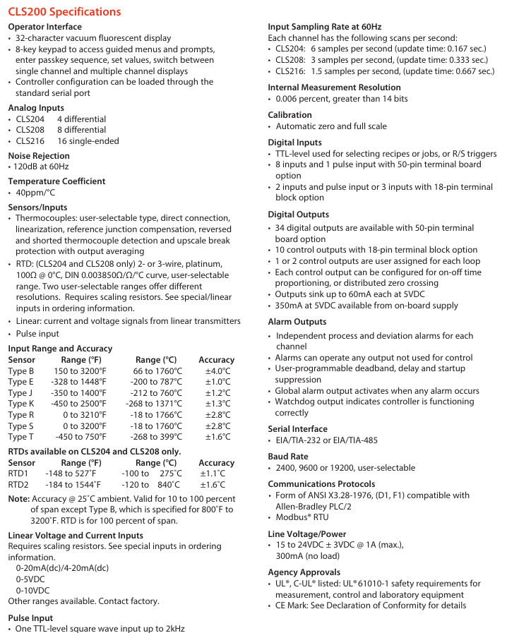
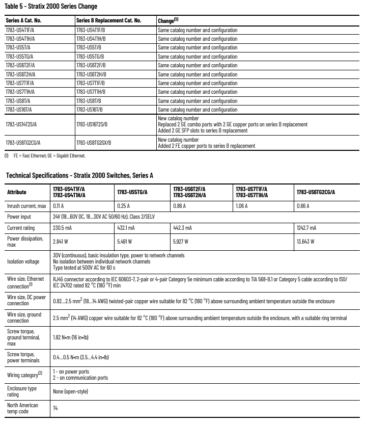
The CLS200 series is a compact loop control system designed in a 1/8 DIN package, offering three versions: 4-loop (CLS204), 8-loop (CLS208), and 16 loop (CLS216), which can cover multi scenario temperature control requirements (such as industrial heating/cooling control, batch processing, etc.). The device supports independent operation and can also be connected to a computer system through serial communication for data acquisition and remote control, in compliance with UL standards ®、 C-UL ®  Certification and EU EMC directive, with CE mark.

2. Core advantages

Advantage categories, specific characteristics, and value

Space and efficiency: Single circuit occupies less panel space, supports multi circuit integration to reduce installation time, and reduces panel layout complexity

Easy to use Auto tune function; 32 character vacuum fluorescent display screen+8-key keyboard, menu guided operation reduces debugging threshold, precise control can be achieved without professional skills; Quickly complete parameter settings

Flexibility supports thermocouples RTD、 Multiple sensor inputs such as linear voltage/current, frequency, etc; 8 homework programs are stored and called to reduce spare parts inventory and learning costs, allowing for quick switching between different process flows

Reliability sensor fault detection (open circuit, short circuit, reverse connection); 34 digital outputs (50 pin terminal board configuration) shorten troubleshooting time and flexibly adapt to control and alarm requirements

Scalability supports EIA/TIA-232/485 serial communication; Optional DAC/SDA analog output module for easy integration with PLC and upper computer, meeting the requirements of analog signal conversion (such as process variable retransmission, motor speed regulation)

Core functions and firmware options

1. Basic control functions

PID control: Supports closed-loop PID control for up to 16 heating/cooling circuits, with 1-2 control outputs per circuit (supporting on/off time ratio and distributed zero crossing triggering).

Alarm function: Each input channel is equipped with independent process alarms (high/low limit) and deviation alarms, supporting user-defined dead zone, delay time, and startup suppression. The global alarm output can be linked to the PLC, and the watchdog output indicates the controller’s operating status.

Data storage: capable of storing 8 job programs, supporting quick calling and switching of processes; The controller configuration can be imported/exported through the serial port.

2. Firmware version selection

Select firmware with different functions according to application requirements, and the core differences are as follows:

Firmware type, core functions, applicable scenarios

Standard firmware includes basic closed-loop PID, automatic tuning, alarm, job storage, sensor fault detection, and conventional temperature control scenarios such as constant temperature heating and simple cooling control

Ramp and Soak firmware includes standard functions+ramp heating/insulation control, process variable retransmission for complex batch processing (such as material aging testing, food processing, requiring staged temperature control)

Enhanced firmware includes standard functions+process variable retransmission, remote simulation set points, cascade control, proportional control, differential control, high-precision linkage control scenarios (such as multi loop coupling temperature control, remote set point adjustment)

Note: The serial control and remote simulation set point functions of the enhanced firmware require 2 controller channels to be occupied; Unused control outputs can be configured for process variable retransmission (with SDAC module).

Detailed explanation of technical parameters

1. Input parameters

(1) Analog input and sensor support

Input type, specific specifications, accuracy (25 ℃ environment)

Thermocouples support Type B/E/J/K/R/S/T, direct connection, with cold junction compensation and linearization; Type B has a range of 66-1760 ℃, while other types have a range of -268~1371 ℃ (depending on the type) ± 1.0~4.0 ℃ (Type E has the highest accuracy and Type B has the lowest accuracy)

RTD (CLS204/208 only) 2/3 wire platinum resistance (100 Ω @ 0 ℃, DIN 0.003850 Ω/Ω/℃), divided into 2 ranges:

-RTD1: -100~275 ℃ (0.1 ℃ resolution)

-RTD2: -120~840 ℃ (1 ℃ resolution) ± 1.1 ℃ (RTD1), ± 1.6 ℃ (RTD2)

Linear input requires an external scaling resistor, supporting 0-20mA/4-20mA DC, 0-5V DC, 0-10V DC, and other ranges can be customized-

Pulse input TTL level square wave, up to 2kHz-

(2) Input performance

Noise suppression: 120dB at 60Hz; Temperature coefficient: 40ppm/℃;

Sampling rate: CLS204 (6 times/second, update time 0.167 seconds), CLS208 (3 times/second, 0.333 seconds), CLS216 (1.5 times/second, 0.667 seconds);

Measurement resolution:>14 bits (0.006% range).

2. Output parameters

Digital output: 34 outputs when configured with a 50 pin terminal board, 10 outputs when configured with an 18 pin terminal board, with a maximum sink current of 60mA (5V DC) per output. The onboard power supply provides 350mA (5V DC);

Analog output: No onboard analog output, requires optional module expansion (DAC/SDC).

3. Communication and Power Supply

Serial communication: EIA/TIA-232 or EIA/TIA-485, baud rates 2400/9600/19200 can be set, supports ANSI X3.28-1976 (compatible with Allen Bradley PLC/2), Modbus ®  RTU protocol;

Power requirements: 15-24V DC ± 3V, maximum 1A (loaded), 300mA (unloaded), optional 120/240V AC to 15V DC adapter (UL) ®  Class 2 certification).

Optional modules (DAC/SDC)

Used to convert the digital output of the controller into analog signals to meet specific control requirements:

Module type, functional specifications, application scenarios

DAC (Digital to Analog Converter) 1-2 distributed zero crossing trigger (DZC) outputs are converted into analog signals, each of which can be configured as 4-20mA DC, 0-5V DC, or 0-10V DC for simple analog signal conversion (such as valve opening control, ordinary speed regulation)

SDAC (Serial Digital to Analog Converter) 1 high-precision analog output (voltage/current), supporting process variable retransmission, open-loop control, motor/belt speed regulation, phase triggered SCR power control, with CE/UL ®/ C-UL ®  Certification of high-precision signal requirements (such as precision instrument temperature control, remote monitoring of process variables)

Module power configuration

Power option specifications support module quantity

A has no power supply-

B 120V AC 60Hz wall mounted power supply (16V DC 300mA) with up to 10 dual DAC modules

H 120/240V AC 50/60Hz adapter (15V DC 1.2A) with up to 12 dual DAC modules

L 120/240V AC 50/60Hz adapter (5V DC 3A) with up to 10 SDAC modules

Ordering Rules and Selection Guide

1. Ordering code for the main controller (Series CLS200)

The code structure consists of 10 bits, and the key bits have the following meanings (see the document “Ordering Information” for the complete structure):

Code bit meaning optional values

② ③ Number of circuits: 04=4 circuits, 08=8 circuits, 16=16 circuits

④ Controller type (firmware) 1=standard, 3=slope insulation, 4=enhanced, C=customized

⑤ Terminal board 0=SCSI interface only, 1=18 pin terminal block (CLS204/208), 2=50 pin terminal block (including 3-foot SCSI cable)

⑥ Power adapter 0=none, 3=120/240V AC to 15V DC (UL) ®  Class 2)

⑦ SCSI cable 0=none (option 0/1), 1=6-foot straight head, 2=3-foot elbow

⑧ Serial communication cable 0=none, 1=10 feet DB-9 female head/bare wire

⑨ Communication jumper 0=EIA/TIA-232, 1=EIA/TIA-485, 2=EIA/TIA-485 terminal matching

⑩ Special input 0/00=thermocouple only/-10~60mV, N/NN=current/voltage/RTD quantity (N is the quantity), XX=custom code

2. Special input selection (10 digits)

If you need to support RTD and linear current/voltage input, you need to specify a special input code:

Special input code type applicable to controllers

20 RTD1 (-100~275 ℃, 0.1 ℃ resolution) CLS204/208

21 RTD2 (-120~840 ℃, 1 ℃ resolution) CLS204/208

44 0-20mA/4-20mA DC Full Series

55 0-5V DC Full Series

56 0-10V DC Full Series

3. DAC/SDAC module ordering code

Code structure: CLSSI+special input type+start channel+end channel, for example, “CLSSI 44 01 04” represents 4-20mA input, covering 1-4 channels.

CyberPower UT650EG / UT850EG User’s Manual

Core Security Directive (Must See)

To avoid fire, electric shock, or equipment damage, the following requirements must be strictly followed:

Installation environment: It can only be used in indoor temperature and humidity controlled environments (see technical parameters for specific range). It is forbidden to expose it to direct sunlight, heat sources (such as heaters and furnaces), do not cover the heat dissipation holes, and stay away from conductive pollutants.

Load limit: It is prohibited to connect non computer devices such as medical/life support equipment, microwave ovens, vacuum cleaners, etc; High power equipment such as laser printers, copiers, and shredders cannot be connected to battery powered sockets (which can easily overload and damage UPS).

Usage taboos: Do not allow liquids or foreign objects to enter the equipment, and do not place liquid containers around UPS; Power off before cleaning, and prohibit liquid or spray cleaners; Battery maintenance should be carried out by professionals and unauthorized personnel are prohibited from accessing it.

Emergency response: In case of emergency, press the “OFF” button and unplug the power cord to cut off the UPS power supply; If overload is detected, the device will sound a long beep alarm, power off and remove at least one load before restarting.

Equipment installation process

1. Open box inspection

The packaging box should contain:

Core components: UPS host (1 unit, UT650EG or UT850EG)

Accessories: User Manual (1 book), USB Data Cable (1 piece, only equipped with UT850EG)

2. Hardware installation steps

Battery charging: The device can be used directly after receiving it, but it is recommended to charge it for at least 8 hours (to offset the power loss during transportation and storage). Simply plug the UPS into an AC outlet (it can be charged in both on/off states).

Load connection: In the power-off state, connect the computer, monitor, and external data storage device to the “Battery Backup&Surge Protected Outlets” and disable high-power devices.

Power access: Insert the UPS plug into a grounded 2-hole 3-wire socket (wall plugs need to be protected by fuses or circuit breakers). Do not share the same circuit with high-power devices such as air conditioners and refrigerators, and try to avoid using extension cords.

Startup: Press the power switch, the power indicator light will turn on and the device will beep once, indicating successful startup.

Overload handling: If overload is detected, the device will sound a long alarm, and at least one load needs to be removed from the power supply. Wait for 10 seconds and confirm that the circuit breaker/fuse is normal before restarting.

Long term maintenance: To maintain the optimal condition of the battery, it is necessary to always connect the UPS to an AC socket; When storing for a long time, it is necessary to fully charge the battery and cover it for storage. Charge it every 3 months to extend the battery life.

Basic Operation Guide

1. Core buttons and interface functions

Function Description of Operating Components

Press and hold the power switch for 2 seconds to turn on/off the device; Quickly press twice to turn on/off the sound alarm (default on, 2 short beeps when turning off the alarm, 1 short beep when turning on the alarm)

The LED indicator light displays the UPS status (such as normal mains power, battery charging, fault, etc., see the “LED Status Definition Table” for details)

USB interface (UT850EG only) connects to the computer’s USB port through PowerPanel ®  Personal software for UPS status communication and monitoring

The battery powered socket provides battery backup and surge protection, providing continuous power supply to the load during power outages

The replaceable fuse provides overload protection. If it melts due to overload, it needs to be replaced according to the specifications

Communication protection ports (RJ11/RJ45) protect modems, fax machines, telephone lines, and network/Ethernet connections from surge damage

2. Definition of LED indicator status

Different colors and flashing modes correspond to different device states, and the key explanation is as follows:

LED color, light status, sound alarm, UPS status, specific description

Green constant light – Energy saving mode (ECO): The mains power is normal, and the UPS is running in energy-saving mode

Green slow flashing – Battery charging is normal, UPS is charging the battery

The yellow light stays on and beeps twice every 30 seconds. The battery mode is interrupted, and the UPS switches to battery power supply

Yellow flashing, fast buzzing, low battery level, battery is about to run out, data needs to be saved and power off as soon as possible

Red constantly on+flashing once every 5 seconds with a continuous beep. Battery output short circuit fault. Power off and remove at least one load before restarting

Red constantly on+flashing twice every 5 seconds, continuous long beep. Overload fault. The load exceeds the rated capacity of the UPS and needs to be powered off to remove some of the load

Red constantly on+flashing 3 times every 5 seconds with a continuous beep. If the charger is faulty, please contact CyberPower technical support

Red constantly on+flashing 4 times every 5 seconds with a continuous beep. Hardware failure requires contacting CyberPower technical support

Red flashing, continuous beeping, overload warning, load overload, power outage is required to remove part of the load

Technical parameters (UT650EG vs UT850EG)

Parameter category UT650EG UT850EG

Capacity (VA/W) 650 VA/360 W 850 VA/425 W

Input voltage range 165~290 Vac; Frequency 50/60 Hz ± 5 Hz (both versions are consistent)

Output battery mode output voltage 220/230/240 Vac; Frequency 50/60 Hz ± 1% (both identical)

Overload protection with built-in current limit and fuse (both versions are the same)

Physical dimensions (width x height x depth) 84 x 174 x 280 mm; weight 3.8 kg Dimensions (width x height x depth) 84 x 174 x 280 mm; weight 4.2 kg

Sealed maintenance free lead-acid battery (model RBP0119 × 1); Charge the sealed maintenance free lead-acid battery (model RBP0143 × 1) to 90% within 6 hours after complete discharge; Charge to 90% within 6 hours after complete discharge

Adapt to working temperature range of 0-40 ℃ in the environment; Relative humidity 0~90% (both versions are the same)

Communication interface without USB interface equipped with USB interface (supports PowerPanel) ®  Software monitoring)

Indicator light/alarm mains/battery/fault indicator light; Supports battery, low battery, overload, and fault alarms (both are the same)

Troubleshooting plan

Common problems, possible causes, and solutions

The UPS battery life did not meet expectations, and the battery was not fully charged; Keep the UPS connected to the power source for charging with slight battery loss; Contact CyberPower technical support to test batteries

UPS cannot be turned on and is not connected to an AC socket; Battery loss; Mechanical fault confirmation connected to 220-240V grounding socket; Contact technical support to replace batteries or repair hardware

The socket has no power supply to overload the load, causing the fuse to melt/the circuit breaker to trip; Battery depletion; The equipment is damaged by a surge, power is cut off, some loads are removed, fuses that meet specifications are replaced or circuit breakers are reset before restarting; Charge for at least 4 hours; Contact technical support for maintenance

Thermal Solutions EVS series gas regulated boilers

Product basic information

1. Core identification and certification

Product positioning: Gas driven modular regulating boiler (GAS-FIRED MODULATION BOILER), used for hot water systems, certified by AHRI, in compliance with the National Gas Code (NFPA 54/ANSI Z223.1) in the United States, the Gas Installation Code (CAN/CSA B149) in Canada, and local regulations such as Massachusetts 248 CMR 4.00/5.00.

Key information: Released in September 2024, replacing the old version, including bilingual warning content in English/French, to be posted and kept clear and readable. Boiler model and serial number (see rated label) must be provided during maintenance.

2. Model and core parameters

Covering 8 models (EVS-500 to EVS-3000), the core parameter differences are as follows (taking typical models as an example):

Model Input Power (MBH) Total Output (MBH) Net AHRI Rated (MBH) Water Capacity (gallon) Dry Weight (pound) Wet Weight (pound) Power Supply/Fan Power

EVS-500 500 431 375 6.1 722 823 120V/189 horsepower

EVS-1000 1000 850 739 16.4 1185 1322 120V/1.5 horsepower

EVS-2000S 2000 1732 1506 40.1 1835 2169 120V/1.5 horsepower

EVS-3000 3000 2610 2270 43.1 2193 2552 208V/2 horsepower

General restrictions: Maximum working pressure of 160 PSI, medium temperature -40~+90 ° C, ambient temperature -40~+85 ° C, condensate pH value 3-5 (requires neutralization treatment).

Installation specifications (key requirements)

1. Pre requirements

Installation qualification: It is required to be operated by a certified Plumber/Gas Fitter (mandatory in Massachusetts). Before installation, local regulations must be confirmed to ensure a safe distance from combustible materials (6 inches left/right/back, 24 inches front, 18 inches for flue connections, and 24-36 inches for maintenance spacing depending on the model).

Space and ventilation: Determine whether a “non confined space” (≥ 50 ft ³/1000 Btu/h) or a “confined space” based on the space volume and total gas input. A confined space requires two permanent ventilation openings (within 12 inches at the top and 12 inches at the bottom, with a minimum diameter of 3 inches); Sealed combustion engine models can be exempted from indoor ventilation, but the intake pipe needs to be installed according to regulations.

2. Core system installation

(1) Ventilation system

Type: Supports positive pressure ventilation (side wall/vertical, maximum equivalent length of 50 feet, non confluent) and negative pressure ventilation (traditional chimney, requiring a vertical height of 15 feet or more and double acting air pressure dampers), ventilation ducts require AL29-4C ®  Wait for condensation resistant materials, tilt the horizontal section at least 1 inch every 4 feet, and keep the terminal away from doors and windows (below 4 feet/horizontal 4 feet/above 1 foot) and gas meters (4 feet).

Special requirements: Massachusetts sidewall ventilation requires the installation of carbon monoxide detectors with backup batteries (1 per floor) and 8-foot high signage (“GAS VENT DirectLY BELOW. KEEP CLEAR”).

(2) Water system

Water quality requirements: hardness ≤ 8.5 grains (150 ppm), pH 8.8-9.2, requiring professional water treatment (anti oxidation, scaling), ethylene glycol usage not exceeding 50%, and rust inhibitor needs to be added; The new pipe needs to be cleaned with trisodium phosphate (TSP), and the old system needs to be equipped with a filter at the return water end.

Pipeline specifications: The supply/return water diameter should be 2-4 inches (depending on the model), and the flow rate should comply with Table 2 (such as EVS-500 minimum 22 gpm, maximum 43 gpm). The return water temperature should not be lower than 130 ° F (anti condensation), and the temperature difference should not exceed 40 ° F (anti heat exchanger damage); Safety valves (not shut-off valves), exhaust devices, and expansion tanks need to be installed.

(3) Gas system

Pressure requirements: The minimum inlet pressure for natural gas is 4-9 inches of water column (depending on the model), for propane it is 8 inches of water column, and for maximum pressure it is 14 inches of water column. For overpressure, an additional pressure regulator must be installed (no multiple boilers can share one); Gas pipes need to undergo leak testing (using soapy water, no open flames), and install sediment traps and manual shut-off valves.

Pipe diameter selection: Refer to Table 4 (such as the equivalent length of 10 feet for a 1-inch SCH40 pipe with a capacity of 514 ft ³/h), and consider the equivalent length of the pipe fittings (Table 6, such as the equivalent length of 1.55-20.2 feet for a 90 ° elbow).

(4) Electrical system

Power supply: requires independent circuit and fuse switch, voltage 120/208/230/460V (depending on model), grounding in accordance with NFPA 70; Do not connect the boiler and circulating pump to the same fuse switch. Isolation relays are required for low voltage control (24V), and short circuiting of safety controls is prohibited.

Operation and debugging process

1. Check before startup

Confirm that the installation of ventilation, water, gas, and electrical systems is compliant, turn off all power sources and gas valves, empty the air in the gas pipeline (wait for 5 minutes), check for no gas leaks, and then open the gas valve.

2. System startup steps

Water injection and exhaust: Close the boiler water supply valve, exhaust in zones (drain to no bubbles for 30 seconds in each zone), fill the system to working pressure, and check for water leakage.

Power on and debugging: Turn on the power, confirm the direction and flow switch function of the circulation pump, and set TSBC ™ Controller (see Chapter 9), check the fan direction (test during pre blowing).

Flame debugging: Verify the ignition flame (blue stable, signal 1.5-5.0 VDC) and the main flame (uniform orange), adjust the air-fuel ratio (high flame O ₂ 4-6%, low flame O ₂ 5.5-7%) to ensure CO ≤ 400 ppm.

3. Conventional operations

Ignition command: via TSBC ™ Activate the controller or external thermostat, manual ignition is prohibited; When you smell gas, turn off all electrical appliances, stay away from the building, and contact the gas supplier/fire department.

Operation monitoring: Real time monitoring of outlet temperature, modulation rate, flame signal to ensure that safety controls such as safety valves, high limit temperature controllers (manually reset), and low water level cut-off devices are functioning properly.

Maintenance and troubleshooting

1. Maintenance cycle and content

Operational requirements for periodic maintenance projects

Daily inspection around the boiler, instrument readings, and flame observation to ensure that there are no flammable materials and no abnormal flames

Weekly igniter, flame signal, gas valve leakage testing, fuel valve closure testing, safety shutdown time

Monthly flue/condensate drainage, gas pressure interlock testing to clean condensate water and ensure pressure is within normal range

Half year instrument calibration, air filter replacement, circulation pump maintenance, filter cleaning with soapy water, pump maintenance according to manufacturer’s specifications

Annual heat exchanger inspection, air-fuel ratio re inspection, safety valve testing, disassembly panel inspection for corrosion, and safety valve testing in accordance with ASME specifications

2. Common fault handling

Possible causes and solutions for alarm information

Low Water Level: The low water level cut-off device triggers a manual reset to check the water replenishment system

Low Water Flow circulation pump malfunction or pipeline blockage, confirm pump operation, clean filter

Fuel Limit gas pressure too high/too low reset pressure switch, check regulator/gas pipeline

High Temp Limit: If the water temperature exceeds the safe value, manually reset the high temperature controller and check the load/circulation system

FSG Fault Flame Protection Device Fault Reset Device, Check Igniter/UV Sensor

3. Spare parts and maintenance

Spare parts ordering: obtained through Thermal Solutions distributors (Lancaster warehouse), providing model and serial numbers; Key spare parts such as heat exchanger (EVS-500:103530-01), fan (EVS-750:81156018), and gas valve (V4295A series) require original factory parts.

Maintenance taboos: Do not disassemble the burner (easily damaged). Before electrical maintenance, all power sources must be cut off and locked. Replacement of controls must be consistent with the original factory model.

TSBC ™ Thermal Solutions Boiler Control

1. Core functions

Support boiler modulation control, multi boiler master-slave linkage (up to 8 units, RJ11 networking), outdoor temperature reset (adjust water temperature according to outdoor temperature, energy-saving), domestic hot water priority (DHWP), fault diagnosis (store 10 alarm records).

2. Key settings

Basic parameters: Warm Season Shutdown (WWSD) set point at 70 ° F, master-slave start triggering 90% modulation rate, stop triggering 25%, rotation period of 168 hours (balanced wear); The default PID parameters are local P=20, I=30, and remote P=20, I=30 (adjustable as needed).

Operation modes: manual mode (setting modulation rate from 0-100%), automatic mode (controlled by outlet/remote temperature), automatic switching to standby mode in case of sensor failure (such as remote sensor failure → outlet sensor control).

Bosch Rexroth HM20 Hydraulic Pressure Sensor

Product basic information

Product model: HM20 (a product under Bosch Rexroth, document number RE 30272, February 2022 edition, replacing April 2018 edition)

Core application: Used for pressure measurement in hydraulic systems. All models with current output have obtained DNV marine certification and are suitable for marine scenarios (requiring additional surge protection)

Key certifications: CE, cUL US Listed, DNV, RoHS, compliant with EMC Directive and UK EMC Regulations (UKCA certification)

Core Features

Measurement capability: Provides 8 measurement ranges (10 bar, 50 bar, 100 bar, 160 bar, 250 bar, 315 bar, 400 bar, 630 bar), using thin film measurement units, with excellent accuracy performance – characteristic curve deviation<0.5% (including nonlinearity, hysteresis, zero and endpoint deviation), non repeatability<± 0.05% (within the reference temperature range)

Material and safety: The medium contact parts are made of stainless steel (1.4542/17-4 PH/630, etc.), and the shell material includes V4A (1.4404), PEI, HNBR; Equipped with high explosive pressure, reverse polarity protection, overvoltage protection, and short circuit protection, the pressure channel is equipped with a 0.3mm throttling element, which can reduce the risk of damage caused by dynamic effects such as pressure peaks and air pockets

Environmental adaptability: Environmental temperature range -40~+85 ° C, medium temperature range -40~+90 ° C, storage temperature range -40~+80 ° C; anti vibration (10-2000Hz/maximum 10g/3-axis), anti noise (20-2000Hz/14g RMS/24h/3-axis), anti transportation impact (15g/11ms/3-axis), protection level IP65/IP67 (requires correct installation of matching connectors)

Technical parameters

(1) General parameters

Category parameter values

Weight 0.06kg

Rated temperature range -25~+80 ° C

Pressure interface G1/4 thread (compliant with DIN 3852 E-type, requiring thorough venting)

Suitable for media HL, HLP, HFC, nitrogen (up to 300 bar), other media can be customized as needed

Tightening torque: 20-25Nm for hydraulic interface<400bar; 25-30Nm for ≥ 400bar; 0.6-1.5Nm recommended for connectors not specified

Life cycle of 60 million load cycles or 60000 hours (CE certified)

(2) Electrical parameters

Category parameter values

The rated power supply voltage is 24VDC, with a lower limit of 18VDC and an upper limit of 36VDC (maximum 30VDC under cULus certification), and the maximum allowable residual ripple is 2.5VSS (40-400Hz)

Current consumption voltage output ≤ 12mA

Protection level III

Insulation resistance>100M Ω (500VDC)

Output signal current output (4-20mA, load resistance R ₐ=(U ₛ -8.5V)/0.0215A); Voltage output (0.1-10V, load resistance R ₐ>2k Ω)

Response speed establishment time (10% -90%)<1ms

Temperature coefficient within the rated temperature range<0.1%/10K; outside the range<0.2%/10K

Long term drift (1 year, baseline conditions)<± 0.1%

(3) EMC compatibility

Immunity: Complies with EN 61000-4 series standards (ESD 4kV CD/8kV AD, surge 1kV, RF radiation 10V/m, etc.)

Emission limit: Complies with EN 55016-2 series standards (interference voltage 0.15-30MHz Class B, radiation field strength 30-1000MHz Class B)

Order code and accessories

(1) Order Code Rules (Example: HM20-2X/- K35-N)

Code bit meaning optional values

Product Type HM20 (Pressure Sensor)

02 Component Series 2X (20-29 Series, with unchanged installation dimensions and pin assignments)

03 Measurement range: 10/50/100/160/250/315/400/630 (corresponding to bar number)

04 Output Type C (4-20mA current output, with DNV certification), H (0.1-10V voltage output)

05 connector K35 (4-pin M12x1)

06 Throttle element N (0.3mm nozzle type)

(2) Optional accessories (need to be ordered separately)

Cable set: 4-pin M12x1 interface, including straight 2m (R900773031), straight 5m (R900779498), bent 2m (R900779504), and bent 5m (R900779503), corresponding to data sheet 08006

Matching connector: 4-pin M12x1 interface, straight PG7 (R900773042), curved PG7 (R900779509)

Replacement seal: NBR material sealing ring (R900012467)

ABB SPAU 341 C Voltage Regulator

Product basic positioning and core functions

1. Product positioning

Application scenario: Designed specifically for on load tap changers in distribution substations, the secondary voltage of the transformer is regulated by controlling tap changers to ensure stable load voltage and adapt to 50/60Hz power grids;

Core value: Supports independent voltage regulation of a single transformer and parallel operation of multiple transformers, with functions such as line voltage drop compensation, overcurrent/undervoltage lockout, overvoltage detection, etc., to meet the stability requirements of industrial power supply;

Module composition: It consists of an automatic voltage regulation module (SPCU 1D50), a manual voltage regulation module (SPCN 1D56), a power module (SPGU 240 A1/SPGU 48 B2), an I/O module (SPTR 6B32), and a motherboard. It supports fiber optic serial bus communication (requires SPA-ZC series bus modules).

2. Core Function List

Functional categories, specific abilities, and application value

Voltage control with automatic/manual dual-mode voltage regulation, adjusting the voltage to adapt to load changes through the “Raise/Lower” signal of the tap changer, and maintaining stable secondary voltage

Compensation function circuit voltage drop compensation (U ₐ), compensating for voltage loss caused by circuit resistance (R) and reactance (X) to ensure that the voltage at the remote load end meets the standard, avoiding high near end voltage/low far end voltage

Protection lockout overcurrent lockout (I>), undervoltage lockout (U<), overvoltage detection (U>), external lockout input prevents the tap changer from operating in fault states (such as short circuit, abnormal voltage), extending equipment life

Parallel operation supports three parallel control principles: Master/Slave, Negative Reaction, and Minimizing Circulating Current. When multiple transformers supply power to the same bus, they balance the load and circulating current to avoid equipment overload

Real time self inspection of self-monitoring hardware/software, triggering IRF (Internal Relay Fault) alarm in case of failure, blocking output to improve system reliability, and reducing the risk of fault expansion

Data exchange with digital display of set/measured values, RS485 serial interface, fiber optic bus communication for convenient on-site debugging and remote monitoring, compatible with substation automation systems

Core working principle and key parameters

1. Voltage regulation core logic

Control voltage calculation: The controller calculates the target control voltage (U ₚ) through “reference voltage (U ₛ) ± line voltage drop compensation (U_z) ± circulating current compensation (U_ci) – set voltage drop (U_rsv)”, and the formula is:

Uₚ = Uₛ ± U_z ± U_ci – U_rsv

Adjustment trigger mechanism:

Compare the measured voltage (U ₘ) with the control voltage (U ₚ). If U ₘ exceeds the “bandwidth (∆ U ₛ)” range (default ± 1.5% U ₙ), initiate the first delay (T1, default 60s);

If U ₘ still exceeds the hysteresis range (∆ U ₕ, default 90% ∆ U ₛ) during the delay period, the tap changer will be triggered;

If a single action does not cause U ₘ to return to bandwidth, initiate the second delay (T2, default 30s) and repeat the adjustment until the voltage meets the standard;

The delay feature supports both “definite time limit” and “inverse time limit” (the delay is inversely proportional to the voltage deviation, and the larger the deviation, the shorter the delay).

2. Key technical parameters (core indicators)

Specific specifications for parameter categories

Voltage input rated voltage U ₙ: 100V/110V/120V (line voltage), continuous withstand voltage 2U ₙ, power consumption<0.5VA, suitable for different regional power grid rated voltages

Current input rated current I ₙ: 1A/5A (optional), 1A model can withstand 4A and 25A continuously for 10 seconds; 5A model can withstand 20A and 100A continuously for 10 seconds, compatible with current transformers (CT) of different transformation ratios

Output contact adjustment contact (Raise/Power): 250V AC/DC, continuous 5A, 0.5s on-off 30A; signal contact (lockout/alarm): 250V AC/DC, continuous 5A, compatible with tap changer drive circuit and alarm circuit

Power module SPGU 240 A1: 80~265V AC/DC (compatible with 110/230V mainstream voltage); SPGU 48 B2: 18~80V DC (compatible with low-voltage DC system) to meet different substation power configurations

Environmental adaptability: working temperature -10~+55 ℃, storage temperature -40~+70 ℃, humidity 5%~95%, non condensing, protection level IP54 (embedded installation), suitable for industrial harsh environment, dustproof and splash proof

Communication capability: Fiber optic serial bus, ASCII encoding, speed 4800/9600 Bd, supports SPA-ZC series modules (SPA-ZC 17/21 for plastic fiber optic and SPA-ZC 17 MM/21 MM for glass fiber optic) to achieve data exchange among multiple regulators, supports parallel operation and remote monitoring

Core configuration and operation process

1. Key configurations before installation (mandatory steps)

(1) Hardware wiring specifications

Core input/output wiring:

Voltage input: X0/13-14 terminals are connected to the secondary side line voltage of the transformer (U ₁₂, 100/110/120V);

Current input: Connect the X0 terminal to three-phase current (1A to 1-3/4-6/7-9, 5A to 1-2/4-5/7-8), and a single transformer can only measure the L1 phase current (selected through SGF2/6/7 software switch);

Control output: X2 terminal outputs Raise/Power signal to the tap changer, X1 terminal connects external control signal (automatic/manual switching, external locking);

Grounding requirement: Connect the protective ground through the X0/63 terminal to ensure reliable grounding between the module and chassis, avoiding electromagnetic interference.

(2) Core parameter setting (configured through panel buttons or serial port)

Parameter Name Setting Range Default Values Key Role

Reference voltage U ₛ 0.85~1.15U ₙ 1.00U ₙ Set target secondary voltage

Bandwidth ∆ U ₛ 0.60~9.00% U ₙ 1.50% U ₙ Voltage fluctuation tolerance range, avoiding frequent adjustments

Delay T1/T2 0.0~300s 60s/30s to prevent momentary voltage fluctuations from triggering misoperations

Overcurrent lockout I>1.00~2.00I ₙ 2.00I ₙ When overcurrent occurs, voltage regulation is prohibited to protect the tap changer

Line compensation U ᵣ/U ₓ 0.0~25.0% U ₙ 0.0% U ₙ Compensation line impedance voltage drop, U ᵣ=√ 3I ₗₒₐ𝒹 R × 100/U ₙ, U ₓ=√ 3I ₗₒₐ𝒹 X × 100/U ₙ

2. Operation mode and process

(1) Automatic voltage regulation mode (default, SPCU 1D50 dominant)

Trigger condition: If U ₘ exceeds the range of ∆ U ₛ and lasts for T1 time, the controller outputs Raise/Power signal to drive the tap changer;

Compensation logic: Based on the load current (I ₗₒₐ𝒹) and the line parameters (R/X), U_z is automatically calculated to increase the remote voltage (such as a line voltage drop of 2V, U_ is automatically increased by 2V).

(2) Manual voltage regulation mode (dominated by SPCN 1D56)

Activation method: Switch through the panel “MAN” button or external “MAN ‘” input, and the MAN indicator light will turn on;

Operation steps: Press the “Raise”/”Lower” button, the corresponding indicator light flashes → Confirm that there is no lock (I>/U<light is not on) → Press the corresponding button again to trigger the tap changer action, and the TCO light is on to indicate that the tap changer is running.

(3) Multiple transformers running in parallel (three modes)

Parallel mode is suitable for key configurations in applicable scenarios

Master/Slave mode: The main regulator of a transformer with the same capacity and tap voltage measures voltage/current and controls it. The slave regulator follows the action of the main regulator and needs to be directly wired to connect the master slave “up/down” output and input

Negative Reaction mode: Transformers with different capacities and tap voltages do not require physical connections. The “load phase shift” parameter is set, and the controller compensates for the voltage deviation between the measured phase shift and the set value, adapting to the parallel connection of dispersed substations

In scenarios where there are large differences in transformation ratio/capacity and large fluctuations in reactive load, the Minimum Circulating Current mode needs to be paired with the SPA-ZC 100 bus module. Multiple regulators exchange current/phase shift data, calculate and minimize circulating current, and support up to 3 parallel regulators

Fault handling and maintenance

1. Interpretation of status indicator lights (core fault diagnosis basis)

Suggestions for handling the meaning of indicator light status

Module status (MS): red, constantly on, unrecoverable fault (such as hardware damage). Power off and restart, if ineffective, check the connection between the I/O module and the motherboard, and contact after-sales service

Overcurrent lockout (I>), red constant light. If the current exceeds the set value, check if the load is overloaded and if the CT wiring is normal. After troubleshooting, reset

Under voltage lockout (U<), red constant light, voltage lower than U<set value (default 0.7U ₙ), check the grid voltage. If the grid is normal, adjust U<set value

Overvoltage detection (U>): The red constant light indicates that the voltage is higher than the set value (default is 1.25U ₙ), triggering “rapid voltage reduction” without manual intervention. After the voltage is restored, it will automatically exit

Self check fault (IRF): The hardware/software fault record of the red module is constantly on, and the display screen shows the fault code (such as 1-030=program memory fault). Contact after-sales maintenance for assistance

2. Common fault codes and their solutions

Fault code, fault type, handling measures

1-004 voltage regulation control circuit fault check tap changer “up/down” coil wiring, confirm power module output voltage

1-030 Program Memory (ROM) malfunction module internal failure, SPCU 1D50 module needs to be replaced

1-050 working memory (RAM) failure, power off and restart. If the failure persists, replace the motherboard

1-051 Parameter Memory (EEPROM) Failure: Format EEPROM with V167 parameters and reconfigure parameters

3. Key points of daily maintenance

Regular inspection: Check the terminal wiring for looseness and proper heat dissipation every month, and clean the module dust screen (if any) every quarter;

Parameter backup: Backup parameters (such as U ₛ, ∆ U ₛ, U ᵣ/U ₓ) through serial software to avoid module failure causing parameter loss;

Spare parts preparation: It is recommended to reserve key spare parts such as power module (SPGU 240 A1) and I/O module (SPTR 6B32) to shorten the time for fault repair.

Installation and selection suggestions

1. Installation requirements

Environmental conditions: Avoid high temperature heat sources (such as the transformer body), installation location temperature ≤ 55 ℃, humidity ≤ 95% non condensing, protection level IP54 (requires compatible casing);

Wiring specifications: Voltage/current signal lines and power lines should be laid separately. The length of the fiber optic bus cable should be ≤ 100m (plastic fiber)/2km (glass fiber), and the bending radius should be ≥ 10 times the cable diameter;

Size and fixation: Adopting embedded installation, the panel opening size needs to match (214 × 139mm ± 1mm), and the installation depth can be adjusted through the SPA-ZX series height increasing frame (3 specifications).

2. Selection and matching

Power module selection: Select SPGU 240 A1 (80~265V AC/DC) for conventional scenarios, and SPGU 48 B2 (18~80V DC) for low-voltage DC systems;

Bus module selection: SPA-ZC 17 BB/21 BB for plastic fiber optic, SPA-ZC 17 MM/21 MM for glass fiber optic, and SPA-ZC 100 BB/MM for parallel minimum circulating current;

Cable selection: 100V shielded wire is used for voltage signals, CT dedicated shielded wire is used for current signals, and ABB recommends plastic/glass fiber optic cables (such as SPA-ZP 25A05) for optical fibers.

Rockwell Automation 1585 Ethernet Media

Document Fundamentals and Product Positioning

1. Core positioning

Application scenario: Suitable for Harsh environment in industrial control field (high vibration, chemical corrosion, wide temperature range, high electromagnetic interference), supporting EtherNet/IP protocol (compatible with CIP protocol of DeviceNet and ControlNet);

Key advantages: The entire series of products comply with standards such as ODVA EtherNet/IP and ISO IEC 24702, providing protection coverage from IP20 (inside the control cabinet) to IP67 (outdoor/equipment end), and supporting a maximum transmission rate of 1Gb/s (Cat 6);

Product matrix: Classified by “cable form+connector type”, covering four major categories: cable reels, RJ45 series, M12 series, and adapters, to meet the needs of different installation scenarios.

2. Core parameters for environmental adaptation

Temperature range: Regular model -20~+60 ℃, wide temperature model -40~+80 ℃ (such as M12 Xcode Gigabit);

Protection level: RJ45 class IP20, M12 class IP67 (splash proof, dustproof);

Anti interference capability: Shielded version (foil+braided shielding) supports high noise environment (M ∝ I ∝ C ∝ E ∝ level), unshielded version reduces interference through twisted pair balanced design;

Weather resistance: TPE/PUR sheathed cables are resistant to welding spatter, ultraviolet radiation, and oil stains, while PVC versions are suitable for conventional industrial environments.

Core product classification and technical specifications

(1) Cable reel: Basic transmission medium

1. Unshielded twisted pair (UTP)

Core parameters: Cat 5e, 24 AWG tinned copper conductor, 4/8 cores (2/4 pairs), supporting 1Gb/s rate;

Sheath type and scenario:

Key Characteristics of Sheath Material Color Adaptation Scene Model Example

Robot TPE green/red bending resistant (10 million cycles), oil/UV resistant robotic arm, mobile device 1585-C4TB Sx (4-core)

Riser PVC green vertical wiring compliance (UL CMR) control cabinet vertical wiring 1585-C8PB Sx (8-core)

Plenum PVC grey smoke and toxic resistant (UL CMP) ventilation duct, cleanroom 1585-C8MB Sx (8-core)

Length options: x=100/300/600m (default unit), for example, 1585-C4TB-S600 is a 600m scroll.

2. Shielded Twisted Pair (STP)

Shielding structure: foil+braided double-layer shielding (some models use single-layer foil shielding), enhancing the ability to resist electromagnetic interference;

Special Style: 600V High Voltage Cable:

Parameters: 22 AWG, 8-core (4 pairs), -20~+80 ℃, UL PLTC/AWM 2570 certification;

Scenario: Installed on the same cable tray as the high-voltage power cable (such as near the motor control cabinet), models 1585-C8HB Sx (green) and 1585-C8EB Sx (red).

(2) RJ45 series: inside control cabinet/conventional connection

1. Conventional RJ45 jumper (IP20)

Core specifications: Cat 5e/Cat 6, 4/8 cores, supporting 6 connection combinations including straight head straight head, straight head elbow (left/right), etc;

Classification and Scenarios:

Type Sheath Material Shielding/Non Shielding Key Characteristics Model Example

Regular PVC (riser) unshielded/shielded control cabinet fixed wiring, UL CMR 1585J-M8PBJM-y (8-core straight head)

High flexibility TPE unshielded with 10 million bending cycles, compatible with mobile parts 1585J-M8TBJM-y

600V high voltage PVC foil shielding high voltage environment isolation, UL PLTC 1585J-M8HBJM-y

Length options: y=2/5/10m (default unit), for example, 1585J-E4TBJM-5 is a 5m right elbow jumper.

2. Gigabit RJ45 jumper (Cat 6)

Differentiated parameters: 8-core (4 pairs), foil+braided shielding, TPE sheath, -40~+75 ℃, supporting 1000Mbps;

Scenario: High speed industrial Ethernet (such as machine vision, large data transmission), model 1585J-M8TGJM-x (straight head straight head).

3. On site connectors can be connected

Two types of styles:

IDC tool free connector: Cat 6, 24-27 AWG (solid core/multi strand), 360 ° shielding, can be reused 5 times, model 1585J-M8CC-H (single pack);

Crimp connector: Cat 5e, 24~26 AWG, with protective boots, 50 pieces (1585J-M8CC-C);

Advantages: No need to strip wires, simplifying on-site wiring modifications, and adapting to custom cable length requirements.

(3) M12 series: Harsh environment specific

4-core D-code (conventional industrial)

Core features: IP67 protection, 4-core (2 pairs), Cat 5e, Support -40~+75 ℃ (TPE/PUR sheath);

Classification and Scenarios:

Example of Key Characteristics and Models for Shielded/unshielded Sheath Material (Jumper)

TPE unshielded high flexibility (10 times cable diameter bending radius) 1585D-M4TBJM-x (M12-RJ45)

PUR foil+woven shielding halogen-free, chemical corrosion resistant 1585D-M4UBJM-x

PVC foil shielding 600V high voltage isolation 1585D-M4HBJM-x

Special Edition: Red M12: Identify high voltage/safety circuit, model 1585D-M4VBDM-x (TPE unshielded).

2. 8-core X-code (gigabit high-speed)

Differentiated parameters: Cat 6, 8-core (4 pairs), foil+braided shielding, -40~+80 ℃, supporting 1Gb/s;

Scenario: High speed transmission in Harsh environment (such as outdoor sensor networking), providing M12-M12 (1585D-M8UGDM-1) and M12-RJ45 (1585D-M8UGJM-1) jumpers with customizable lengths.

3. M12 socket (front end installation)

Features: IP67, 4-core D-code, TPE/PUR sheath, suitable for fixed installation at the device end;

Model: 1585D-D4TBJM-x (unshielded TPE), 1585D-D4UBJM-x (shielded PUR), length 1-15m optional.

(4) Adapter: Transition across protection levels

1. M12-RJ45 wall adapter

Core function: Implement the transition from IP67 (M12 at the device end) to IP20 (RJ45 inside the control cabinet), and support panel installation (PG9 thread);

Parameters: 4-core D-code, IP67, -20~+85 ℃, 22 AWG, model 1585A-DD4JD;

Scenario: Connection between on-site equipment such as motors and sensors and control cabinets.

2. M12 IDC on-site connector

Features: Tool free installation, 4-core D-code, optional shielded/unshielded, IP67, -25~+85 ℃;

Model: 1585D-M4DC-SH (shielded straight head), 1585D-F4DC-SH (shielded elbow), compatible with 22-26 AWG cables.

Key selection dimensions and precautions

1. Three core dimensions for selection

(1) Environmental protection requirements

IP20 scenario (inside control cabinet): Select RJ45 unshielded/shielded jumper (such as 1585J-M8PBJM-y);

IP67 scenario (device side/outdoor): Select M12 series (such as 1585D-M4TBJM-x);

High voltage/strong interference scenario: Choose a 600V shielded version (such as 1585-C8HB Sx cable, 1585J-M8HBJM-y jumper).

(2) Transmission rate and distance

100Mbps (regular control): Cat 5e, with a maximum length of 100m for unshielded models (at 500kbps), and up to 150m for shielded models;

1Gb/s (high-speed data): Cat 6 (M12 Xcode), up to 100m (twisted pair), requires matching shielding design to reduce crosstalk.

(3) Mechanical characteristics

Fixed wiring: choose PVC sheath (low cost, high stability);

Mobile components (such as robotic arms): Choose TPE/PUR high flexibility models (10 million bends, such as 1585-C4TB Sx cables).

2. Precautions for installation and use

Bending radius: High flexibility cables should be ≥ 10 times the cable diameter, while conventional cables should be ≥ 20 times to avoid excessive bending and transmission attenuation;

Shielding grounding: Shielding models require single ended grounding (on the control cabinet side) to avoid ground circulation caused by double ended grounding;

Color identification: The red version is used for high-voltage/safety circuits, while the green and green versions are used for regular signals to avoid mixing;

Tool adaptation: IDC connectors do not require tools, while crimping connectors require specialized crimping tools (such as 1585A-JCRIMP).

Certification compliance

Safety certifications: UL Listed, cUL, CE (EN 61000-6-2/-4), C-Tick (Australia);

Industry standards: ODVA EtherNet/IP, ISO IEC 24702, TIA 568-B (wiring standard).

Typical application scenario configuration example

Robot workstation: M12 D-code high flexibility jumper (1585D-M4UBJM-2)+TPE cable reel (1585-C4TB-S300), suitable for -40~+75 ℃, high vibration environment;

Outdoor sensor networking: M12 Xcode Gigabit jumper (1585D-M8UGDM-5)+600V shielded cable (1585-C8HB-S600), resistant to ultraviolet and high-voltage interference;

Wiring inside the control cabinet: RJ45 straight head elbow jumper (1585J-E8PBKM-3)+PVC cable reel (1585-C8PB-S100), low-cost compatible with IP20 environment.

Through the above product combination, industrial Ethernet can achieve full scene coverage from “control cabinet field equipment outdoor node”, ensuring stable transmission in Harsh environment.

Rockwell Automation SmartGuard 600 Controller

Basic and Controller Core Positioning

1. Basic information

Document purpose: To guide the installation, parameter configuration, wiring, and status interpretation of safety controllers, suitable for deployment in industrial safety scenarios such as emergency stop and safety door monitoring;

Controller positioning: Programmable Electronic Safety System (PES), supporting 16 digital inputs, 8 digital outputs, 4 test pulse outputs, 1752-L24BBBE with additional support for EtherNet/IP communication;

Safety certification: meets high safety level requirements – IEC 61508 SIL 3, ISO 13849-1 PL (e), EN 954-1 CAT 4, suitable for hazardous environments (North American Class I Div 2 Groups A-D).

2. Comparison of Model Differences

Model Core Differences Communication Interface Applicable Scenarios

1752-L24BBB Basic Security Control USB+DeviceNet Security Scenarios without Ethernet Requirements (such as Single Device Security Monitoring)

1752-L24BBBE adds Ethernet functionality USB+DeviceNet+EtherNet/IP for distributed security systems that require remote Ethernet monitoring (such as production line level security linkage)

Key configurations before installation (mandatory steps)

1. Safety prerequisite requirements

Precautions for hazardous environments:

It is strictly prohibited to plug and unplug wires with electricity (which may cause arcing and explosion). Power must be cut off or the environment must be confirmed to be in a non hazardous area first;

Prohibition of replacing non original components (which may damage Class I Div 2 compatibility);

Battery replacement is only allowed in non hazardous areas.

Electrostatic protection: Before operation, touch a grounded object to discharge electricity, wear an anti-static wristband, prohibit touching circuit board pins, and store in anti-static packaging when idle.

2. Core parameter configuration (power-off operation)

(1) DeviceNet node address setting

Configuration method: Set through the two rotary switches (ten position+one position) on the front of the controller, with a range of 00~63 (default 63);

Software configuration compatibility: If setting the address through RSNetWorx for DeviceNet software, the rotary switch needs to be turned to 64~99;

Key reminder: Avoid duplicate node addresses, otherwise communication errors may be triggered.

(2) DeviceNet communication rate setting

Default speed: 125 kbps, supports three speeds of 125/250/500 kbps, configured through a 4-digit DIP switch:

DIP switch (1-4) communication rate description

OFF-OFF-OFF-OFF 125 kbps default value

ON-OFF-OFF-OFF 250 kbps medium range networking

OFF-ON-OFF-OFF 500 kbps short distance high throughput scenario

The software configuration of ON-ON-OFF-OFF needs to be set through RSNetWorx

Speed and distance matching: The higher the speed, the shorter the supported cable length (such as 75m for flat cables and 100m for thick cables at 500 kbps), which needs to be selected according to the network size.

(3) EtherNet/IP IP Address Setting (1752-L24BBBE only)

Default mode: BOOTP enabled, IP needs to be allocated through BOOTP server (recommended Rockwell free tool, download link: http://www.ab.com/networks/bootp.html );

Configuration steps:

Run the BOOTP tool and double-click on the device MAC address;

Enter the target IP in the pop-up window and click confirm;

The IP address of the controller can be viewed on the display screen through the front “IP Address Display Switch” (long press for more than 1 second), and error code “n4” indicates abnormal Ethernet configuration.

Controller installation and wiring specifications

1. Physical installation (DIN rail fixation)

Installation requirements:

Only supports EN 50022 standard DIN rails (35×7.5mm or 35x15mm), horizontal installation (vertical installation may affect heat dissipation);

Heat dissipation gap: at least 50mm (2.0in) up and down, and at least 5mm (0.20in) left and right, avoiding installation above heating equipment;

Installation steps:

Hang the top card slot of the controller on the DIN rail;

Press the bottom of the controller and tighten the bottom buckle (1752-L24BBB single buckle, 1752-L24BBBE double buckle);

Install end plates at both ends of the guide rail to ensure stability.

Grounding requirements: Chassis grounding is achieved through DIN rails, which require the use of galvanized yellow chromium steel rails (aluminum/plastic rails may cause poor grounding), and the rails should be fixed every 200mm (7.8in).

2. Power wiring (safety power supply is the core)

Power specifications:

External power supply: 24V DC (allowable range 20.4~26.4V DC), output holding time ≥ 20ms;

Safety compliance: Must meet SELV/PELV (CE LVD), Class 2 (UL 508), and recommend Rockwell 1606 series power supplies (such as 1606-XLP30E, 1606-XL60DR);

Terminal wiring:

The controller includes 3 sets of V/G terminals (V0/G0: internal logic power supply; V1/G1: Input and test output power supply; V2/G2: Safe output power supply);

The V0/G0 two sets of terminals are internally connected, only one set needs to be connected, and the other set can be used to distribute power to other devices.

3. I/O and communication wiring (according to scene specifications)

(1) Input wiring (compatible with two types of devices)

Mechanical contact equipment (such as emergency stop button): It is necessary to simultaneously connect the “safety input terminal (INx)” and the “test output terminal (Tx)” to achieve CAT 4 level, with a wiring length of ≤ 30m;

PNP semiconductor devices (such as safety light curtains): only connected to the safety input terminal (INx), no need to test the output, typical current is 4.5mA.

(2) Output wiring (distinguishing between safety and test outputs)

Safe output (OUT0~OUT7): Maximum load 0.5A, wiring beyond the rated value is strictly prohibited, and it is not allowed to be used as a test output;

Test output (T0~T3): Only used for input circuit testing, T3 additionally supports wire breakage/bulb burnout detection and cannot be connected to safety loads.

(3) Communication wiring

DeviceNet wiring: 5-wire connector, corresponding by color (red V+, white CAN H, blue CAN L, black V -, empty Drain), screw torque 0.25~0.3N · m;

USB wiring: only for temporary configuration (non permanent connection), cable length ≤ 3m, USB-A to USB-B male to male cable is required;

EtherNet/IP wiring (only 1752-L24BBBE): RJ45 interface, CAT5e/CAT5 cable, length ≤ 100m, pins 1 (TD+), 2 (TD -), 3 (RD+), 6 (RD -).

image.png

Interpretation of Status Indicators and Troubleshooting

1. Meaning of core indicator lights (sorted by classification)

(1) Module status (MS) indicator light

Suggestions for handling the meaning of indicator light status

Turn off the power supply and check the power wiring. Restart the power supply

Green constantly on, normal operation (Run mode), no operation required

Green flashing standby mode (Idle) to confirm if the configuration is complete

Red flashing can restore faults (such as configuration errors). Check the switch configuration and reset the configuration data

The red light is constantly on and cannot be restored due to a fault (such as hardware damage). Check the wiring, eliminate interference, and contact after-sales service

Red green alternating flashing self-test/configuration download waiting for completion. If it continues to flash, it needs to be reconfigured

(2) Network status indicator light

DeviceNet (NS D): Green constant light=online and connected, red constant light=MAC address conflict/bus disconnection, address and cable need to be checked;

EtherNet/IP (NS E, BE only): Green constant light indicates Ethernet connection, red constant light indicates IP address conflict, IP needs to be reassigned.

(3) I/O status indicator light

Yellow constant light=signal normal, red constant light/flashing=circuit fault (such as disconnection, short circuit, overcurrent), wiring and load need to be checked.

2. Interpretation of Display Screen Information

Normal state: Display node address (00~63), standalone mode displays “nd”;

Fault status: alternately display error codes and node addresses (such as F0=MAC conflict, F1=bus disconnection);

Special function: Press the “Service Switch” to display the security configuration signature (verifying that the program has not been tampered with), press the “IP Display Switch” to display the Ethernet IP.

Key specifications and supporting resources

1. Core technical parameters

Specification item 1752-L24BBB 1752-L24BBBE

Size (HxWxD) 99×99.4×131.4mm 99x113x131.4mm

Weight 460g 575g

Working temperature -10~55 ℃ (14~131 ℉) same as left

Protection level IP20, same as left

Input current 4.5mA (per channel) same as left

Output current 0.5A (per channel, maximum) same as left

Ethernet speed -10/100Mbps (full/half duplex)

2. Supporting resources

Key manuals:

SmartGuard 600 User Manual (1752-UM001): Controller Configuration and Troubleshooting;

SmartGuard 600 Safety Reference Manual (1752-RM001): Safety Concepts and PFD/PFH Calculations;

tool

Configuration software: RSNetWorx for DeviceNet (DeviceNet configuration), BOOTP tool (IP configuration);

Core safety operation reminder

Prohibited behavior:

Test outputs cannot be used as safety outputs, and safety signals cannot be transmitted using DeviceNet standard I/O data;

It is prohibited to disassemble/modify the controller (which may damage safety functions);

Do not allow the 24V DC line to accidentally touch the output terminal to avoid starting the load.

Wiring specifications:

Input/output cables should be arranged separately from high-voltage/high current cables to avoid interference;

Stranded wires require the installation of DIN 46228-4 standard insulated Ferrules (non-standard Ferrules may not match the terminals).

Rockwell Automation 1756 ControlLogix Communication Module

Basic Information and Module Classification

1. Basic information

Document positioning: Technical manual for industrial grade ControlLogix communication module, including module selection, parameter configuration, installation requirements, suitable for building and maintaining industrial control networks;

Core coverage: 7 types of networks (EtherNet/IP, DeviceNet, DH+, Remote I/O, DH-485, SynchLink, ControlNet), 3 types of special modules (conformal coating, XT wide temperature, legacy obsolete);

Module model system: Named according to “network type+functional characteristics”, such as 1756-EN2T (EtherNet/IP network, 2-port), 1756-DNB (DeviceNet network), suffix “K” represents normal coating (anti-corrosion), “XT” represents wide temperature environment (-25~70 ℃).

2. Overview of module classification

Network type, core module model, functional positioning, special version

EtherNet/IP 1756-EN2F/EN2TT/EN2TP/EN2TR/EN3TR/EN4TR/ENBT Industrial Ethernet Bridge, supporting real-time I/O and message communication 1756-EN2TK (coating), 1756-EN2TXT (wide temperature)

DeviceNet 1756-DNB/E connects the underlying network bridging of sensors/actuators-

DH+/Remote I/O 1756-DHRIO, 1756-RIO/B DH+message communication, Remote I/O scanning/adaptation 1756-DHRIOXT (wide temperature)

DH-485 1756-DH485 low-cost serial communication network-

SynchLink 1756-SyncH fiber optic synchronous communication for distributed motion control-

ControlNet 1756-CN2/CN2R/CNB/CNBR legacy control network, real-time high-throughput 1756-CN2RK (coating), 1756-CN2RXT (wide temperature)

Legacy 1756-EWEB (web server) and 1756-TIME (time synchronization) have been discontinued and alternative solutions are provided-

image.png

Core network module technical specifications (sorted by network type)

(1) EtherNet/IP module: Industrial Ethernet core

1. Core functions and selection criteria

Key capabilities: Supports CIP protocol (real-time I/O+message communication), DLR ring network (1756-EN2TR/EN3TR/EN4TR), PRP redundancy (1756-EN2TP/EN4TR, firmware 4.001+), CIP Security encryption (1756-EN4TR);

Selection Comparison Table:

Module model, port specifications, maximum number of connections (TCP/CIP), packet rate (PPS), and adaptation scenarios

1756-ENBT 1 × RJ45 (10/100Mbps) 64/128 5000 (I/O)/900 (HMI) basic Ethernet networking

1756-EN2T 1 × RJ45 (10/100Mbps) 128/256 25000 (I/O)/2000 (HMI) Medium scale I/O control

1756-EN4TR 2 × RJ45 (10/100/1000Mbps) 512/1000 (I/O)+528 (message) 50000 (unencrypted)/15000 (encrypted) large redundant network, supporting 256 axis motion

1756-EN2TXT (wide temperature) 1 × RJ45 (10/100Mbps) 128/256 25000 (I/O) Extreme temperature environment (-25~70 ℃)

2. Common technical parameters

Power supply: 5.1V DC (current 0.7~1.2A), partially supporting 24V DC auxiliary power supply;

Environmental adaptability: Operating temperature of 0-60 ℃ (conventional)/-25~70 ℃ (wide temperature), humidity of 5%~95%, non condensing, ESD resistance (contact with 6kV/air 8kV);

Certification: c-UL-us (Class I Div 2), ATEX Zone 2, CE, RCM, compliant with ODVA EtherNet/IP.

(2) DeviceNet module: underlying device networking

Core parameters: 1756-DNB/E supports 125/250/500kbps communication rate, maximum 64 nodes, 24V DC (11-25V) power supply, current 60mA;

Key features: Supports CIP protocol, adapts to sensors/actuators, USB port for temporary configuration (prohibited for use in hazardous environments);

Environment and Certification: Operating temperature range of 0-60 ℃, certified with EtherNet/IP module, compliant with ODVA DeviceNet.

(3) DH+/Remote I/O module: legacy network compatible

1756-DHRIO (dual function)

DH+function: Supports speeds of 57.6/115.2/230.4kbps, with a maximum of 32 message connections;

Remote I/O function: As a scanner, it supports 32 logical racks and 16 block transfer connections;

Parameters: 5.1V DC current 850mA, operating temperature 0~60 ℃ (conventional)/-25~70 ℃ (XT model).

2. 1756-RIO/B (Remote I/O only)

Function: Supports scanner/adapter mode, 32 physical racks, transfers analog/digital/block data;

Restriction: When used as an adapter, it must be paired with a ControlLogix controller.

(4) ControlNet module: Legacy High Throughput Network

Core parameters: Communication rate of 5Mbps, maximum 99 nodes, 1756-CN2/CN2R supports 128 Logix connections, 1756-CNB/CNBR supports 40-48 connections;

Redundancy feature: 1756-CN2R/CNBR supports dual port redundancy to ensure uninterrupted network operation;

Alternative suggestion: It is recommended to migrate to EtherNet/IP, refer to the “ControlNet to EtherNet/IP Migration Reference Manual” (CNET-RM001).

(5) Other network modules

1756 SynchLink: Fiber optic communication (650nm wavelength, 200/230 μ m HCS fiber), speed 5Mbps, high synchronization accuracy, used for multi chassis motion coordination;

1756-DH485 (DH-485): speed of 9.6/19.2kbps, 2 DB9 ports, requires a 1761-NET-AIC converter to connect to the network and adapt to old devices.

image.png

Special version and Legacy module description

1. Special version module

Conform coating version (suffix K): such as 1756-EN2TK, 1756-CN2RK, anti salt spray, corrosion, suitable for humid/chemical environments;

XT wide temperature version (suffix XT): such as 1756-EN2TXT, 1756-DHRIOXT, working temperature -25~70 ℃, in compliance with ANSI/ISA-S71.04 G1/G2/G3, suitable for extreme industrial environments.

2. Legacy module (discontinued)

1756-EWEB: discontinued in November 2021, alternative solution is 1756-CMS1B1/CMS1C1 (Compute module);

1756-TIME: discontinued in November 2021, replaced by Aparian A-TSM/B time synchronization module( https://www.aparian.com/products/timesync ).

Common technical requirements and supporting resources

1. General parameters

Power supply and power consumption: Most modules rely on ControlLogix chassis 5.1V DC power supply, with a power consumption of 3.5~6.7W, and some require 24V DC assistance;

Installation requirements: 1 slot width, suitable for chassis such as 1756-A4/A7/A10, recommended power supply 1756-PA75/PB75 (regular), 1756-PAXT/PBXT (XT wide temperature version);

Electromagnetic compatibility (EMC): compliant with IEC 61000-6-2/-4, resistant to radiated interference (10V/m, 80-2000MHz), and resistant to EFT (± 3kV, 5kHz).

2. Key attachments

Network Type Attachment Model Description

EtherNet/IP 1585J-M8PBJM-x Ethernet jumper (2/5/10m, Cat5e/Cat6)

DeviceNet KwikLink Lite flat cable and IDC connector, fast networking without wire stripping

ControlNet 1786-RG6 quad shielded coaxial cable, 1786-TCT2BD1 (IP67 T-connector)

DH+1770-CD Belden 9463 dual axis cable, 9300-RADKIT (remote dialing kit)

Selection and migration suggestions

Priority for new projects: prioritize the selection of EtherNet/IP modules (1756-EN4TR/EN2TR), which support redundancy, encryption, and motion control, and are compatible with future expansion;

Legacy network maintenance: DH+/ControlNet module is only used for upgrading existing systems. It is recommended to migrate to EtherNet/IP for new scenarios;

Special environment adaptation: Choose the “K” coating for humid/corrosive environments, and the “XT” wide temperature version for high and low temperature environments to ensure compliance with on-site protection levels;

Module replacement for elimination: 1756-EWEB/1756-TIME needs to be replaced according to the recommended document plan to avoid operational risks in the later stage.

image.png

Rockwell Automation Stratix series Ethernet devices

Overview of Basic Information and Equipment Categories

Basic information

Document positioning: Technical specification manual for industrial grade Ethernet equipment, including detailed parameters, compatibility, installation requirements, suitable for equipment selection, deployment, and maintenance;

Applicable brands: Allen Bradley Stratix series, some including ArmorStratix (reinforced) sub series;

Core coverage categories: There are a total of 16 types of devices, divided into switch categories (10 types), routing/security categories (3 types), wireless categories (1 type), and auxiliary technology categories (2 types), as follows:

Switches: Stratix 2000 (unmanaged), 2100 (unmanaged), 2500 (light managed), 5200 (managed), 5400 (managed), 5410 (managed), 5700 (managed), ArmorStratix 5700 (reinforced managed), 5800 (modular managed), 6000 (managed);

Routing/Security Category: Stratix 4300 (Remote Access Router), 5900 (Service Router), 5950 (Security Gateway);

Wireless category: Stratix 5100 (wireless access point/workgroup bridge);

Assistive technology: Embedded switching technology (Ethernet Taps), configurable NAT routers, CIP security agents.

Core equipment technical specifications (sorted by category)

(1) Switch category: classified by “non network management/light network management/network management”

1. Non managed switch: Stratix 2000/2100

Core features: No complex configuration function, plug and play, focusing on basic data transmission;

Key parameter comparison:

Equipment model, port specifications (typical), power supply range, operating temperature, protection level

Stratix 2000 (Series B) 5-18 ports (FE/GE RJ45+SFP, partially pre installed multi-mode/single-mode SFP) 12-48V DC, 18-30V AC -10~60 ℃ (base version)/-40~75 ℃ (wide temperature version) IP30

Stratix 2100 5-18 ports (FE/GE RJ45+SFP, including PoE) 12-48V DC, 24V AC -40~75 ℃ IP30

Special design: Stratix 2000 Series A/B, optimized port configuration for Series B (such as replacing 1783-US14T2S/A with 1783-US16T2S/B and adding 2 GE SFP slots).

2. Light network management switch: Stratix 2500

Core function: Supports basic VLAN and IGMP snooping, without complex routing functionality;

Key parameters: Only 2 models (1783-LMS5/8), 5-8 FE copper cables, power supply 12-24V DC, working temperature -20~60 ℃, protection IP30, simple networking suitable for industrial control scenarios.

3. Network management switch: 5200/5400/5410/5700/ArmorStratix 5700/5800/6000

Common features: Supports Layer 2/Layer 3 protocol, CIP Sync (IEEE 1588), DLR ring network NAT, Partial includes PoE/PoE+(30W/port);

Differentiated parameters (typical models):

Model Port Capability Power Supply and PoE Budget Wide Temperature Capability Special Advantages

5200 (1783-CMS10DN) 8GE+2GE combo 12-48V DC, no PoE -40~60 ℃ support PRP redundancy, TSN ready

5410 (1783-IMS28GNDC) 12GE+4GE SFP+12PoE 24-60V DC, single power 60W/dual power 185W -40~60 ℃ with conformal coating, suitable for harsh environments

ArmorStratix 5700 (1783-ZMS8TA) 8FE, M12 interface 9.6-60V DC, no PoE -40~60 ℃ IP66/IP67 protection, reinforced shell for impact resistance

5800 (1783-MMS10EAR) 8GE+2GE SFP (modular, expandable 16 ports) 12-54V DC, PoE total budget 360W -40~60 ℃ supports hot swappable expansion modules, suitable for large-scale networking

6000 (1783-EMS08T) 8FE+1SFP 24V DC, no PoE 0~60 ℃, compact size, compatible with substations (IEC 61850-3 compatible)

(2) Routing/security devices

1. Stratix 4300 Remote Access Router

Core capability: Supports both wired (LAN/WAN) and wireless (Wi Fi 802.11a/b/g/n/ac, 4G LTE CAT4) dual-mode, with a maximum data rate of 1.73 Gbps (Wi Fi) and 150 Mbps (4G download);

Key parameters: Power supply 9-34V DC, operating temperature -20~65 ℃ (non wireless version)/-20~60 ℃ (wireless version), including Bluetooth 5.1, compatible with remote industrial site networking.

2. Stratix 5900 Service Router

Positioning: Small industrial service routing, supporting VPN and firewall;

Parameters: Power supply 5V DC (requires external adapter), operating temperature -25~60 ℃, protection IP30, suitable for lightweight remote management scenarios.

3. Stratix 5950 Security Gateway

Core functions: CIP Security encryption, port isolation, support for 100/1000Base-T/SFP;

Parameters: Power supply 12-48V DC, working temperature -40~60 ℃, including alarm relay (30V DC/1A), suitable for industrial network security isolation requirements.

(3) Wireless device: Stratix 5100 wireless access point

Coverage scenario: Industrial wireless networking, supporting access point/bridge mode;

Key parameters: dual frequency (2.4GHz/5GHz), external antenna, power supply 48V DC (PoE), operating temperature -20~55 ℃, protection IP30, regional models (US/Canada/EU/China, etc., suitable for local frequency bands).

(4) Assistive technology category

Embedded Switching Technology (Ethernet Taps): including copper/fiber optic cables (1783-ETAP/ETAP1F), supporting 100Base-T/FX, operating temperature -25~70 ℃, used for network traffic monitoring;

Configurable NAT router (1783-NATR): 2-port Ethernet, powered by 20.4-27.6V DC, operating temperature -25~70 ℃, compatible with small network address translation;

CIP Security Proxy (1783-CSP): Supports CIP protocol encryption (integrity+confidentiality), with a maximum packet rate of 10000 pps (I/O) and a working temperature of -25~70 ℃, enhancing industrial control network security.

Common technical requirements and environmental adaptability

1. General parameters

Power supply commonality: Most support 12-48V DC (SELV level), some include AC power supply (100-240V AC);

Protection level: Conventional equipment IP20/IP30, reinforced version (ArmorStratix 5700) IP66/IP67;

Electromagnetic compatibility (EMC): compliant with IEC 61000-6-2/-4, resistant to ESD (contact 6kV/air 8kV), and resistant to radiated interference (10V/m, 80-2000MHz).

2. Environmental adaptability (industrial standard)

Temperature: Most models support -40~60 ℃ (wide temperature range), while some basic models support 0~60 ℃;

Humidity: 5%~95% non condensing;

Mechanical resistance: vibration 2g (10-500Hz), impact 15g (working)/30g (non working), in compliance with IEC 60068 series standards.

Supporting accessories and compatibility

1. Core attachments

SFP module: covering 100Base FX/LX (multimode 2km/single-mode 20km), 1000Base SX/LX (multimode 550m/single-mode 10km), 10GBase SR/LR (multimode 400m/single-mode 10km), partially supporting digital optical monitoring (DOM);

Cable: Industrial grade Ethernet jumpers (CAT5e/CAT6, RJ45/M12 interfaces, shielded/unshielded), cable reels (100-600m);

Storage media: Industrial SD card (1784-SD1/SDHC8), CompactFlash card (1783-MCF/RMFC), compatible with device configuration storage.

2. Compatibility rules

SFP compatibility: GE SFP is only compatible with GE slots (e.g. Stratix 2000 GE slots only support 1783-SFP1GSX/GLX);

Firmware requirements: Some modules require specific firmware versions (e.g. 1783-SFP100T requires Stratix 5400 firmware 3.001+);

Expansion module adaptation: Stratix 5800/8000 only supports expansion modules of the same series (such as 5800 adapted to 1783-MMX16T).

Certification

Core certification (common across the entire series)

Security certification: c-UL-us(UL 61010-1)、CE(EMC/RoHS)、ATEX(II 3 G Ex nA IIC T4 Gc)、IECEx( Same as ATEX level);

Industrial protocol certification: ODVA EtherNet/IP compliant, partially compliant with IEEE 1613 (substations) and IEC 61850-3 (power automation).

Key selection suggestions

Adverse environment (dust/humidity): ArmorStratix 5700 (IP67) or Stratix 5410 (conformal coating) is preferred;

PoE demand scenarios: Stratix 5410 (dual power 185W budget), 5800 (360W total budget), compatible with cameras and sensor power supply;

Remote networking: Stratix 4300 (4G+Wi Fi) is suitable for industrial sites without wired coverage;

Security isolation: Stratix 5950 (CIP Security) and 1783-CSP (Protocol Encryption) are adapted to control networks that require tamper proof measures.

A-B Ultra3000 and Ultra5000 with DeviceNet

The Ultra3000 is an easy-to-use, high-performance, digital servo drive in a compact package.  

Reduced size, high performance and low cost make the Ultra3000 an attractive solution for a wide variety of applications.  

It is ideal for stepper, stand-alone indexing, or standard velocity or position control.  

With DeviceNet, users can dynamically adjust and change Ultra3000 commands from a PLC or Operator Interface.  

The Indexing option combined with DeviceNet allows the end user to perform complete motion profiles over DeviceNet.  

DeviceNet communication also provides Ultra3000 system diagnostics at the system controller.

The Ultra5000 is a complete single-axis motion control system that includes an intelligent motion controller and digital drive in an integrated package.

The Ultra5000 is tailored for high-speed motion processing, position capture, and advanced math capabilities to increase application performance. 

When communicating over the DeviceNet network, the Ultra5000 user program can dynamically adjust to changing commands and parameters from a supervisory PLC or Operator Interface. 

Multiple Ultra5000 Drives can be networked with a single PanelView Operator Interface for a cost-effective application solution.

The Ultra5000 satisfies the most challenging motion control tasks, including feed-to-length, flying shear, high-speed packaging, labeling and stamping applications.

DeviceNet Features and Benefits

• single DeviceNet connector eliminates control to drive wiring and

reduces installation cost

• remote parameter download and configuration of drive

• status LEDs for easy local assessment of module and network status

Product Features and Benefits

• rotary selector switches for setting address and communication rate

• plugable terminal block connectors (catalog number 1787-PLUG10R)

• minimal wiring, resulting in reduced start-up time

• inter-operability with other manufacturers’ components

• rapid troubleshooting and equipment repair

• modification of individual device parameters using the network

• UCMM for remote parameter configuration

image.png

Precautions

Safety specifications are generally applicable to control system handling. Instructions and warnings related to a specific subject or operation of the product.

The following norms must be strictly observed:

  must strictly comply with the technical specifications and typical applications of the product system

  Personnel training: Only trained personnel shall install, operate, maintain or repair the product system. must

Provide guidance and explanation of the situation in danger areas to these personnel.

  Unauthorized changes: Changes or structural changes to the product system may not be made.

  Maintenance responsibility: Must ensure that the product system is used only under appropriate conditions and in full fitness for use.

 Working environment: The user must meet the specified environmental conditions:

Safety regulation

The following safety provisions of EN 50110-1 shall be fully complied with when handling product systems (maintenance) :

1 Disconnect completely.

2 Secure to prevent reconnection.

3 Verify that the installation is complete.

4 Ground and short-circuit the device.

Warning: Only qualified maintenance personnel can remove and insert the module. In order to ensure the personal safety of the operator, before each pulling out or inserting, you must

Disconnect the power supply and ensure that there is no voltage on all terminals at the back, and the product is effectively grounded with the ground screw at the back.

Installation precautions

First, the importance of industrial equipment installation

In modern industrial production, various equipment and machines are widely used in various fields, such as manufacturing, energy industry, chemical industry and so on. The installation of industrial equipment is directly related to production efficiency and product quality. Proper installation and commissioning of good equipment can ensure the stable operation of the production line, improve production efficiency and product quality, reduce maintenance costs, and ensure the safety of employees.

Second, the steps of industrial equipment installation

1. Preparation: Before the installation of industrial equipment, it is necessary to carry out adequate preparation work. This includes the tools and equipment required for installation, cleaning and preparation of the installation site, and making installation plans and schedules.

2. Determine the installation position: Determine the installation position of the equipment according to the requirements of the equipment and the layout of the production line. When determining the location, the weight and size of the equipment need to be considered, as well as the coordination of the equipment with the surrounding environment.

3. Install the device: Assemble and install the device according to the installation instructions. Ensure that the device is securely and accurately connected, while protecting the appearance and internal components of the device.

4. Connect power supplies and pipelines: For devices that require power supplies and power supplies, properly connect power supplies and pipelines. The connection of power supply and pipeline should comply with safety standards to avoid hazards such as electric shock and leakage.

5. Commissioning the device: After the installation is complete, you need to commission the device to ensure that the device can run properly. It includes checking the functions and performance of the equipment, adjusting the parameters and Settings of the equipment, and carrying out the necessary tests and inspections.

6. Training operators: After the installation of the equipment, it is necessary to train the operators to understand the operation methods and precautions of the equipment, and improve the operation skills and safety awareness of the employees.

Third, industrial equipment installation precautions

1. Safety first: When installing industrial equipment, safety is the most important consideration. You must operate in strict accordance with safety regulations and wear necessary protective equipment to ensure the safety of the workplace.

2. Strictly follow the equipment instructions: Industrial equipment usually comes with detailed installation instructions, you must carefully read and understand the contents of the instructions, and install the operation in accordance with the requirements of the instructions.

3. Pay attention to the assembly sequence: When installing the device, follow the correct assembly sequence to ensure that all components of the device are assembled correctly to avoid equipment failures or safety accidents caused by incorrect assembly sequence.

Applicable Industries

petroleum

Natural gas

chemical industry

cement

metallurgy

ship

mining industry

aviation

transport

Alcoa

machinery

manufacturing

car

Search for products

Back to Top
Product has been added to your cart