Call us 24/7uaedcs@163.com
Welcome to the official website of CNIACS Automation Technology Co., Ltd!
Call us 24/7uaedcs@163.com

YASKAWA GA800 Industrial AC Inverter

Overview

This document is the GA800 Industrial AC Inverter Selection Guide (document number SL. GA800.01) released by Yaskawa USA in 2021. It introduces the multi voltage levels (240V/480V/600V), dual duty ratings (Normal Duty/Heavy Duty), and corresponding model parameters of GA800 inverters, covering core data for inverter selection (such as output current, power range), supporting components (reactors, filters, braking units, etc.), configuration package solutions (Type 1/12/3R enclosure), technical parameters (overload capacity, protection level, etc.), as well as training services and sales terms, providing comprehensive selection support for Yaskawa salespeople, distributors, and partners.

GA800 inverter core selection parameters

1. Voltage and power range (key numbers)

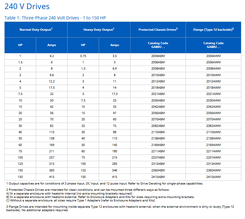
Voltage level, phase number, power range (HP), core model example, applicable scenarios

240V Class 3-phase 1-150 2004ABM (1HP ND), 2360AWM (150HP ND) low-power motors, such as small pumps/fans

480V Class 3-phase 1-1000 4002ABM (1HP ND), 4H12AAM (1000HP ND) medium and high-power equipment, such as compressors/machine tools

600V Class 3-phase 125-500 5125ABM (125HP ND), 5472AWM (500HP ND) high-voltage industrial scenarios, such as large transmission systems

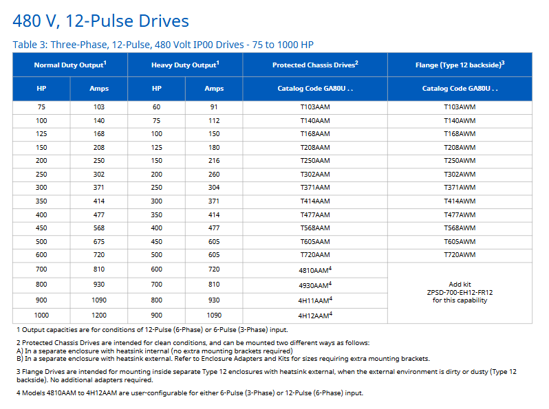
Scenarios where harmonic reduction is required for 480V 12 Pulse 3-phase 75-1000 T140AAM (100HP ND) and 4H12AAM (1000HP ND), such as medical equipment

2. Performance rating and overload capacity

Normal Duty (ND): Suitable for larger motors, overload capacity of 110% rated current x 60 seconds

Heavy Duty (HD): Stronger torque, overload capacity of 150% rated current x 60 seconds

Example: 240V model 2030ABM, ND 10HP (30A), HD 7.5HP (25A)

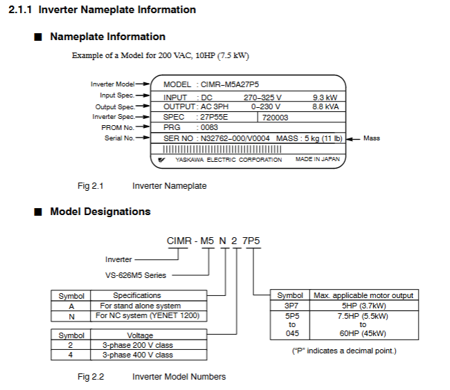
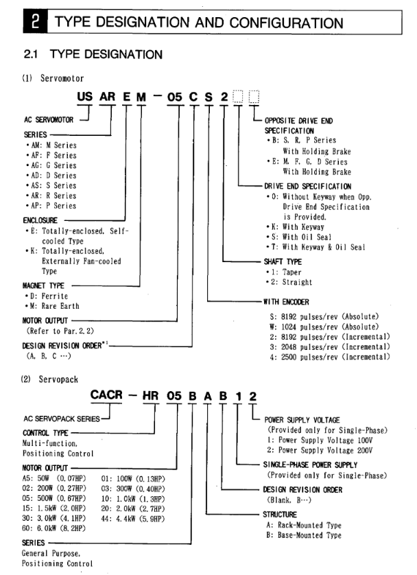
3. Model coding rules (taking “GA80U 2 004 ABM” as an example)

Encoding segment meaning optional values/description

GA80U series identification fixed prefix (Americas region)

2 voltage levels 2=240V, 4=480V, 5=600V, T=12 pulse 480V

004 output current corresponds to ND rated current (unit: A, here it is 4A)

A protection level A=IP00, B=IP20, W=Type 12 flange

B environmental specification B=humidity/dust protection (compliant with IEC 60721-3-3 Class 3C2/3S3)

M EMC filter M=Not used (A=Not used, some models in the document default to no filter)

Single/three-phase input adaptation and component selection

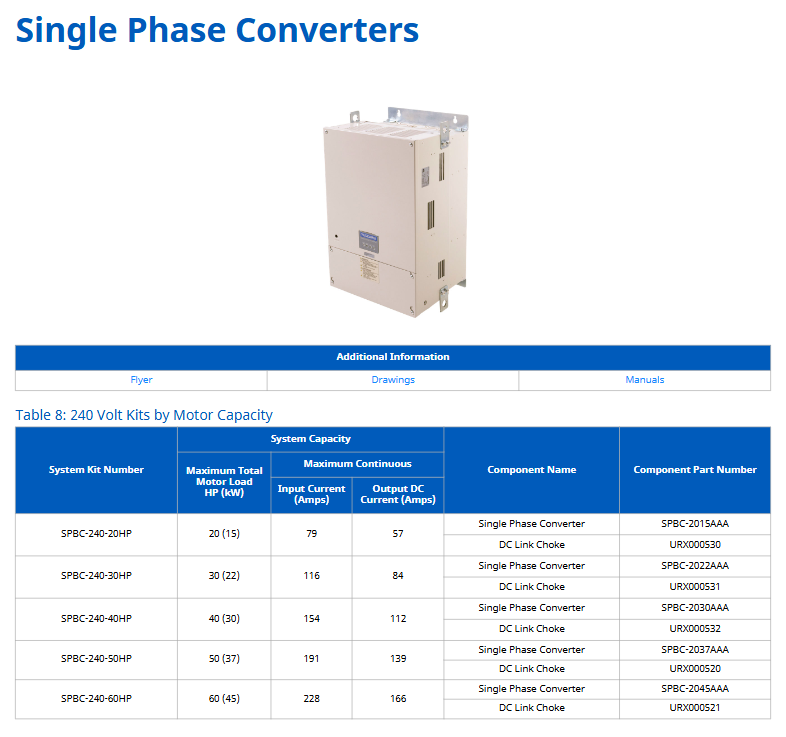
1. Single phase input configuration (requires reduced capacity, some require reactors)

Taking 240V single-phase input as an example, the core parameters are as follows (excerpt from Table 5):

Drive model (GA80U) without reactor (ND/HD) with reactor (ND/HD) Input reactor model (Open)

2004… 1/3HP(1.5A)/1/2HP(2.2A) -/- URX000303

2008… 3/4HP(3.2A)/1HP(4.2A) -/- URX000307

2030… 2HP(6.8A)/5HP(15.2A) -/- URX000323

2. Core supporting components

(1) Reactor and Filter

Component Type Impedance Options Installation Form Core Function Example Model (480V)

DC Bus Reactor 3%/5% Open/Enclosed Type 1 reduces DC side transients and decreases THD URX000033 (3% Open) and URX000215 (3% Enclosed)

AC Input Reactor 3%/5% Open/Enclosed Type 1 suppresses input side harmonics and protects the frequency converter  URX000288(3% Open)、URX000551(3% Enclosed)

AC Output Reactor 3% Open/Enclosed Type 1 reduces motor side voltage spikes and is compatible with long cables  05P00620-0014(Open)、05P00620-0016(Enclosed)

EMC Input Filter – Integrated to EN 61800-3 C2 level, reduces electromagnetic interference B84743A00008R176 (8A), B84243A6180Z000 (180A)

(2) Braking unit

Dynamic braking:

3% duty cycle: operates for 3 seconds within a 100 second cycle, with resistance models such as R7504 (240V) and R7508 (480V)

10% duty cycle: operates for 10 seconds within a 100 second cycle, requiring the use of transistor modules (such as CDBR-21100D) and resistors (such as URS000275)

Regenerative braking (R1000):

Suitable voltage: 240V (5-150HP), 480V (5-500HP)

The kit includes: R1000 module, current suppression reactor, power coordination reactor, fuse

Example: R1000-480-50HP kit, including R1000 module model 4A0035AAA

(3) Control and Feedback Attachment

Attachment Type Function Description Model Example

I/O adapter AI-A3: 3 additional analog inputs (13 bits+symbol) AI-A3

Motor feedback card PG-X3: Incremental encoder interface (line driven type) PG-X3

Network Communication Card SI-P3: PROFIBUS-DP Communication Interface SI-P3

Operation keyboard with Bluetooth LCD keyboard: supports mobile APP control-

Remote Cable UWR0052: Keyboard Remote Cable (3m) UWR0052

GA800 configuration package scheme (Type 1/12/3R)

1. Configure the core parameters of the package (taking 480V Type 1 ND as an example)

Rated current (A), nominal HP (ND), basic model, optional power options, optional control options

2.1 G8C1B002 E (standard circuit breaker), C (65kAIC circuit breaker), T+C (PROFINET), T+H (PROFIBUS)

40 30 G8C1B040 P+EX (3% Bus Reactor), F (Input Fuse), T+D (EtherNet/IP), A (Analog Input)

180 150 G8C1B180 M (100kAIC circuit breaker), R (3% Line reactor), T+Q (Modbus TCP), X (PG-X3 feedback)

2. Shell type and environmental adaptation

Shell type, protection level, applicable environmental temperature range, special options

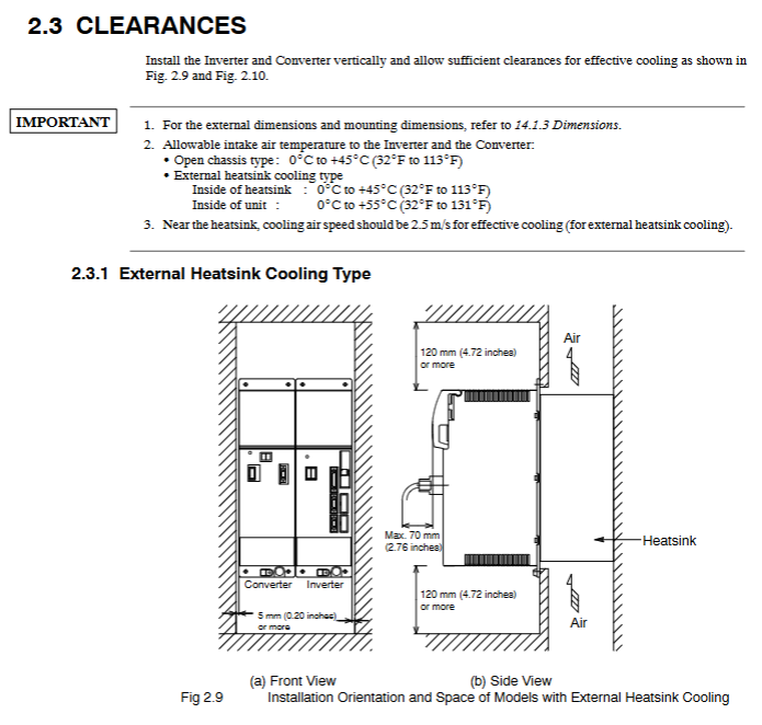
Type 1 IP30 (adapted) cleanroom (such as electronic workshop) -10~+40 ℃ space heater, blower starter

Type 12 IP54 (external heat sink) for dusty environments (such as machinery factories) -10~+50 ℃ external heat sink adapter

Type 3R IP54 (weatherproof) outdoor/humid environment (such as pump station) -10~+50 ℃ (optional 50 ℃ adaptation) independent support leg (UUX000923, 12 inches), lightning arrester

Technical parameters and environment Derating

1. Key technical specifications

Project specification description

Output frequency 0-590Hz

Control mode: open-loop/closed-loop vector, open-loop/closed-loop V/f

Motor compatibility sensitive motor, surface permanent magnet motor (SPM), built-in permanent magnet motor (IPM), synchronous reluctance motor

Standard I/O with 8 digital inputs (24Vdc), 3 analog inputs (0 ± 10V/4-20mA), and 3 relay outputs

Safe Torque Off (STO), SIL3 (IEC 62061), PLe (ISO 13849-1)

Certified UL, CSA, CE, RCM, RoHS, SEMI-F47, IEEE1668

2. Derating rules for the environment

Temperature Derating:

When the ambient temperature is greater than 40 ℃ (Type 1)/greater than 50 ℃ (IP20), for every 1 ℃ increase, the output current will decrease by 2%

Altitude Derating:

≤ 1000m: No capacity reduction

1000-4000m: For every 1000m increase, the output current decreases by 8%

Voltage Derating (altitude>2000m):

Neutral grounding system: No need to reduce capacity

Non neutral grounding system: higher voltage level needs to be selected (such as 600V frequency converter for 480V scenario)

VYASKAWA AC Drive V1000 Compact Vector Control DriveV

Basic information of the document

Applicable models: 200V level (single-phase input 0.1-4.0kW, three-phase input 0.1-18.5kW), 400V level (three-phase input 0.37-18.5kW) CIMR-V series frequency converters.

Core purpose: To guide users in correctly installing, operating, and debugging frequency converters, ensuring safe and stable operation of the equipment.

Copyright and Revision: First published in 2007, latest revised in December 2016, including updates to safety standards, functional supplements, and more.

Key content of core chapters

1. Safety instructions and warnings

Risk classification: Clearly define three types of warnings: Warning (fatal/serious injury), CAUTION (minor/moderate injury), and NOTICE (equipment damage).

Core taboos: Do not modify equipment, touch terminals before discharge, and operate by non professionals; Strict adherence to grounding regulations is required (leakage current exceeding 3.5mA, grounding conductor cross-section ≥ 10mm ² (copper)/16mm ² (aluminum)).

Special risk: During the rotation self-tuning period, the motor may suddenly start, and after power failure, it is necessary to wait for the capacitor to fully discharge (at least 5 minutes).

2. Mechanical installation

Environmental requirements: Indoor installation, temperature -10~+50 ℃ (adjusted according to protection level), humidity ≤ 95%, no condensation, no dust, oil pollution, vibration and other interference.

Installation specifications: Vertical installation is required to ensure heat dissipation, and 30mm (on both sides) and 100mm (up and down) heat dissipation space should be reserved around the equipment.

Acceptance and verification: After receiving the goods, check that the equipment is not damaged and verify the nameplate to confirm that the model is correct.

3. Electrical installation

Wiring specifications: The main circuit power supply is connected to R/L1, S/L2, T/L3 (only R/L1, S/L2 are used for single-phase), the motor is connected to U/T1, V/T2, W/T3, and it is forbidden to connect the power supply to the output terminal.

Cable requirements: The control circuit should use shielded twisted pair cables to avoid mixing with the main circuit cables; The specifications of the main circuit cables need to match the model (such as 2.5mm ², 6mm ², etc.).

EMC compliance: A designated EMC filter must be installed on the input side, and the grounding surface must be repainted to ensure low impedance.

4. Keyboard operation and startup debugging

Keyboard functions: including RUN/STOP start and stop keys, parameter setting keys, mode switching keys (LOCAL/REMOTE), LED indicator lights to display running status, faults, and other information.

Start up process: Install wiring → Power on → Select control mode (V/f, open-loop vector, etc.) → Set load type (standard/heavy load) → Motor self-tuning (or manually input motor parameters) → I/O configuration → Trial operation → Load operation.

Mode selection: V/f control is suitable for multi motor drive, open-loop vector control is suitable for high-precision speed regulation, and open-loop vector control of permanent magnet motor focuses on energy saving.

5. Key parameters and troubleshooting

Core parameters: including frequency reference (b1-01), acceleration and deceleration time (C1-01/C1-02), motor rated current (E2-01), overload protection (L1-01), etc.

Troubleshooting: List common faults (such as overcurrent, overvoltage, overload) and their corresponding causes and solutions, including troubleshooting methods for programming errors (oPE series) and self-tuning errors (Er series).

Safety disable function: Compliant with SIL2/PL safety standards, controlled through HC and H1 terminals, the motor torque is cut off within 1ms when disconnected, requiring professional personnel to wire and debug.

6. UL/cUL compliance requirements

Installation restrictions: Pollution level ≤ 2, ambient temperature -10~+50 ℃ (depending on protection level).

Wiring specification: Use UL certified copper wire, and the terminal tightening torque must comply with the standard (such as 0.8-1.0N · m for M3.5 terminals).

Protection configuration: The input side needs to be equipped with a specified type of fuse (such as Class J/T/CC), and the motor overload protection is set through parameters E2-01 and L1-01.


Precautions for use

Operators must possess professional qualifications and strictly adhere to the safety regulations outlined in the manual.

The equipment needs regular inspection and maintenance, with daily safety function checks. It is recommended to replace it after 10 years of use.

When the safety disable function is not used, the HC and H1 terminals must be kept short circuited; Modifying the equipment will result in the expiration of the warranty.

YASKAWA Control Pack CP-317M System Controller

Core advantages and features

1. High performance and high reliability

Adopting a 32-bit high-speed processor, the program processing speed is doubled compared to the previous generation, coupled with large capacity memory, to meet the computational needs of complex applications.

No cooling fan design, natural cooling is used to deal with the heat generated during high-speed operation, reducing mechanical failure points.

Equipped with a large capacity FPGA to enhance self diagnostic capabilities, and equipped with battery backup memory with ECC (error checking and correction) function to ensure data reliability.

2. Comprehensive compatibility

The software, size, and bus interface specifications are fully compatible with the previous generation CP-317, and all optional modules of the original CP-317 can be used directly.

Only a single operating module (CPU) needs to be replaced to upgrade the existing system, without the need to restructure the overall configuration, reducing upgrade costs.

3. Flexible scalability

Supports single CPU or dual CPU configuration (Changan installation base can accommodate 2 CPUs), dual CPUs can independently run different software, support synchronous/asynchronous scanning, and easily transfer up to 32K words of data through shared registers.

Up to 4 racks can be expanded, and various communication and I/O modules can be connected through expansion modules (EXIOIF). Some modules (such as LIO-01, AI-01, etc.) can be configured without restrictions.

Supports various open field networks such as PROFIBUS-DP, FL Net, DeviceNet, etc., to meet the communication needs of different industrial scenarios.

4. Convenient operability

Paired with CP-717 Engineering Workstation (EWS), it supports desktop (via CP-215 real-time network/Ethernet) and laptop (via RS-232C/Ethernet) connections, covering the entire process from system design to maintenance.

Support programming methods such as ladder diagrams and Sequential Function Diagrams (SFC), provide visual programming and online monitoring functions, simplify coding and debugging of complex configurations.

Equipped with functions such as direct parameter adjustment, data tracking (in list/chart format), and rapid fault location, it enhances operational efficiency.

Key specification parameters

1. Power supply and environment

Power module options: PS-01 (100VAC/100VDC), PS-02 (200VAC), PS-03 (24VDC), with voltage fluctuation range of ± 15%~± 20%, supporting instantaneous power outage within 10ms.

Working environment: temperature 0 ° C~55 ° C (24-hour average ≤ 50 ° C), humidity 5%~95% RH (non condensing), no corrosive gases, vibration and impact resistance in accordance with JIS B 3502 standards.

Grounding requirements: protective grounding resistance ≤ 100 Ω, insulation resistance ≥ 5M Ω (500VDC).

2. Performance parameters

Memory configuration: The program memory is equivalent to 128K steps, and the data memory includes 32768 words of input/output registers, 1024 words of system registers, etc. The battery backup can retain data for more than 1 year.

Running speed: Relay command 0.05 μ s/step, addition and subtraction operation 0.1 μ s/step, multiplication and division operation 0.1 μ s~0.3 μ s/step.

Supports data types such as bits, integers, double precision integers, real numbers, etc., with 133 built-in instructions covering program control, numerical operations, I/O control, and other functions.

Main components and models

1. Core components

CPU module (87317-3500x-S060y): Supports single/multiple CPU configurations.

Power modules: PS-01 (100VAC/100VDC), PS-02 (200VAC), PS-03 (24VDC).

Communication module: covering CP-213/215/216/217/218 and other series, supporting Ethernet, RS-232C/485, PROFIBUS-DP and other protocols.

I/O module: including digital input (DI-01), digital output (DO-01), analog input (AI-01), analog output (AO-01), etc., supporting local I/O and extended I/O connections.

2. Installation and Cable

Installation base: MB-01 (long base, single/multi CPU configuration), MB-03 (short base, single CPU configuration).

Expansion cables: EXIO expansion cables, 2000 I/O expansion cables, etc. are available, with lengths ranging from 0.5m, 1.0m, 1.5m, and other specifications.

Applicable scenarios

Mainly used for centralized control in industrial scenarios such as steel plants, water supply and drainage plants, and sewage treatment plants, it can serve as the main control station for medium and large factories, achieving integrated control of equipment such as frequency converters, sensors, and actuators. It supports networking and linkage with HMI (such as CP-519, CP-5800), other PLCs, computers, and other equipment.

YASKAWA VARISPEED-626M/656MR5 series vector control

Document Fundamentals and Product Overview

Document positioning: Yaskawa VARISPEED-626M5656MR5 series user manual, mainly used for vector control inverters/converters with power regeneration function for machine tools, guiding installation, maintenance, troubleshooting, and specification inquiry.

Product model and specifications:

Product Type Model Voltage Level Power Range (kW) Power Range (HP) Remarks

Variable frequency drive (VS-626M5) CIMR-M5 200V level 3.7/2.2-37/30 5/3-50/40 including M5A (independent drive), M5N (NC system)

Variable frequency drive (VS-626M5) CIMR-M5 400V level 5.5/3.7-45/37 7.5/5-60/50 including M5A (independent drive), M5N (NC system)

Converter (VS-656MR5) CIMR-MR5 200V class 3.7/2.2-37/30 5/3-50/40, including MR5A (without 24V control power supply) and MR5N (with 24V control power supply)

Converter (VS-656MR5) CIMR-MR5 400V class 5.5/3.7-45/37 7.5/5-60/50 including MR5A (without 24V control power supply), MR5N (with 24V control power supply)

Warranty information:

Warranty period: 12 months after delivery to the customer or 18 months from the date of shipment from the Yaskawa factory, whichever comes first.

Warranty scope: Only covers faults caused by defects in Yaskawa craftsmanship or materials, excluding improper maintenance, modification, and use beyond specifications.

Regional restrictions: Warranty services are only free within Japan and require payment overseas.

Safety regulations and operating taboos

Definition of Security Level:

Warning: Potential hazardous situation that, if not avoided, may result in death or serious personal injury (such as opening the cover with electricity, not grounded).

CAUTION: Potential hazardous situation that, if not avoided, may result in minor/moderate personal injury or equipment damage (such as grabbing the front cover during transportation or installing on flammable materials).

Core security precautions:

Power off operation: Before wiring or disassembling the digital operator (JVOP-132), the power must be turned off and the capacitor must be discharged (refer to the warning label time, usually 5 minutes).

Grounding requirements: 200V level grounding resistance ≤ 100 Ω, 400V level grounding resistance ≤ 10 Ω. It is strictly prohibited to share the ground with welding machines and high current equipment.

Temperature control: The ambient temperature of the frequency converter/inverter should be ≤ 55 ℃ (131 ° F), and the inlet temperature of the heat sink should be ≤ 45 ℃ (113 ° F). A fan or cooling device should be installed.

Operation taboos:

Do not connect the power supply to the output terminals of the frequency converter (U/T1, V/T2, W/T3), otherwise it will damage the internal components.

Do not connect phase-shifting capacitors, LC/RC noise filters, or electromagnetic switches in the output circuit, as it may cause damage or overcurrent to the frequency converter.

Do not modify the product, otherwise the warranty will expire and may cause electric shock/injury.

Equipment installation and wiring

Delivery Confirmation (CAUTION):

Check if the model is consistent with the order (verify the nameplate), if there is no transportation damage to the appearance, if screws or other components are loose, and if damaged/missing equipment is not allowed to be installed.

Installation requirements:

Environment: Indoor, no corrosive/explosive gases, no dust/metal particles, avoid direct sunlight, vibration acceleration ≤ 2.5G (10-60Hz).

Installation material: It must be installed on non combustible materials such as metal.

Distance requirement (to ensure heat dissipation):

Equipment type, left and right spacing, up and down spacing, note

External heat dissipation type ≥ 120mm ≥ 120mm Side spacing ≥ 5mm

Open chassis type ≥ 150mm ≥ 150mm Side spacing ≥ 5mm

Wiring specifications:

Main circuit wiring: Use the specified wire diameter (such as 200V level frequency converter CIMR-M5A23P7, main circuit wire diameter ≥ 2mm ²), and the terminal screw torque meets the requirements (such as M5 screw 2.35N · m).

Control circuit wiring: Separate the control signal line from the power line, with a length of ≤ 20m, and use shielded twisted pair to avoid wiring in the same conduit.

Core functions and operations

Digital Operator (JVOP-132):

Function: Display operating status (motor speed U1-01, torque reference U1-04), set control constants, fault reset, single machine trial run.

Operation mode: Set from positions 1 to 37, with 11 being the digital operator operation mode, which can achieve jog (5% rated speed) and forward/reverse control.

Trial operation process:

Check the power supply voltage (200V level 3-phase 200-230V, 400V level 3-phase 400-460V).

(NC system) Set YENET1200 node address (rotary switch SW1).

Connect the control power supply and confirm that the frequency converter displays “-” and the inverter displays “- U”.

Connect the main circuit power supply, the inverter display changes to “- b”, and the CHARGE light is on.

Check the direction of the motor cooling fan (standard intake from the load side).

Send RUN signal to confirm the motor direction (counterclockwise when viewed from the load end during forward rotation) and no abnormal vibration/noise.

Directional control:

Encoder directional control:

Resolution: 360 °/4096=0.088 °, repeatability accuracy ± 0.2 °.

Applicable scenario: The load shaft is connected 1:1 to the motor shaft and requires a load shaft encoder (such as NE-1024-2MDF-068).

Magnetic sensor directional control:

Repetition accuracy ± 0.2 °, using magnet (MG-1378BS) and magnetic sensor (FS-1378C), detection range ± 15mm.

Troubleshooting and Maintenance

Common faults and solutions:

Fault code, fault type, cause, and handling measures

AL-01 inverter overcurrent output short circuit, ground fault check wiring, confirm no short circuit

AL-11 main circuit overvoltage input voltage is too high, load inertia is large. Check the power supply and adjust the acceleration time from C1 to 10

AL-20 winding switching fault switching was not completed within the specified time. Check the contactor wiring and confirm the C1-25 motor code

Maintenance cycle:

Daily inspection: motor abnormal noise, vibration, ambient temperature, display screen values.

Regular inspection:

Remarks on component replacement cycle

Cooling fan has accumulated 20000 hours of operation over 2-3 years

Filter capacitor for 5 years at an ambient temperature of 30 ℃

Motor bearings disassembled and inspected for wear after 12000 hours/2 years

YASKAWA AC Servo Drive HR Series (CACR-HR) Multi

Overview

This document is a multifunctional/positioning control manual for the Yaskawa AC servo drive HR series (model CACR-HR, including rack mounted CACR-HR □□ BAB and base mounted CACR-HR □□□ BB), covering in detail the model identification, rated specifications (such as motor output power 0.07-8.2HP, drive input voltage 100-230VAC), mechanical characteristics (allowing radial/axial loads, anti vibration and anti impact performance), wiring connections (typical connections and terminal definitions for main circuit/control circuit/encoder/brake power supply, etc.) of the servo motor (M/F/G/D/S/R/P series) and servo drive I/O signal operation (2CN/5CN input/output signal timing and function), serial communication (RS422 protocol, supporting baud rates such as 9600/4800), parameter setting (100 parameters, including core parameters such as position loop gain Kp and speed loop gain Kv), display/monitoring function (LED indicator light and 7-segment digital tube status display), installation and wiring specifications, trial operation and maintenance (battery replacement, troubleshooting), while emphasizing safety precautions (such as opening the cover after 5 minutes of power outage, anti electric shock/anti scald measures), providing comprehensive guidance for the selection, installation, debugging and maintenance of servo systems.

Product Model and Configuration

1. Analysis of servo motor models (taking USAGED-13A2 as an example)

Explanation of the meaning of model segmentation

USA product prefix Yaskawa servo motor identification

G series (fully enclosed self cooling type, IP65 protection)

ED structural characteristics with encoder

13 output specification 1.3kW (corresponding to 1.7HP)

A-axis end specification with keyway

2 encoder types incremental 8192P/R

2. Analysis of servo drive models (taking CACR-HR03BAB12 as an example)

Explanation of the meaning of model segmentation

CACR-HR Product Series Yaskawa HR Series Servo Drivers

03 Output capacity 300W (0.4HP)

BAB installation and power supply B=rack mounted, A=single-phase, B=200VAC

12th Design Version 12th Design

3. Matching principle between motor and driver

Power matching: The output capacity of the driver needs to cover the rated power of the motor (such as a 300W motor matched with HR03 series driver).

Voltage matching: 100V motor (R series DS model) matches HR □□ BAB11 driver, 200V motor matches HR □□ BAB12/BB driver.

Encoder matching: The absolute encoder motor requires the driver to support battery backup (the HR series panel comes with a 3.6V battery).

Rated specifications and mechanical characteristics

1. Core specifications of servo motors (examples by series)

Motor series model example Rated output Rated speed Rated torque Peak torque Encoder type

M-series USAMED-03B2 0.3kW (0.4HP) 1000r/min 2.84N · m 8.92N · m incremental 8192P/R

S-series USASEM-15A2 1.5kW (2.1HP) 3000r/min 4.90N · m 13.7N · m incremental 2048P/R

R series (200V) USAREM-05CS 500W (0.67HP) 3000r/min 1.59N · m 4.76N · m absolute formula 8192P/R

P Series USAPEM-07CW 750W (1.0HP) 3000r/min 2.39N · m 7.06N · m Absolute 1024P/R

2. Core specifications of servo drive

Driver model input power output current (continuous/peak) control mode protection function

CACR-HR03BAB12 single-phase 200-230VAC 2.7A/7.8A full wave rectification+PWM sine wave drive OC, OV, OL, PG disconnection, etc

CACR-HR15BB three-phase 200-230VAC 11.7A/33.0A full wave rectification+PWM sine wave drive OC, OV, OL, phase loss (O-PH), etc

CACR-HR05BAB11 single-phase 100-115VAC 5.5A/16.3A full wave rectification+PWM sine wave drive OC, OV, OL, battery low voltage (BATALM), etc

3. Mechanical characteristics (motor)

Allowable load: Radial load 78.4-1764N (such as S series 02A model 78.4N, M series 60B model 1764N), axial load 39.2-588N.

Environmental tolerance:

Temperature: 0-40 ℃ for operation, 20-60 ℃ for storage;

Vibration: below 15 μ m (10-50Hz);

Protection level: IP44 (S/R series), IP65 (M/F/G/D/P series, excluding shaft ends).

Connection and wiring

1. Typical connection circuit

Main circuit connection: three-phase/single-phase power supply → circuit breaker (MCCB) → noise filter → servo driver (R/S/T) → motor (U/V/W).

Control circuit connection:

I/O signals: 2CN (servo enable SVON, start AST), 5CN (manual operation MCW/MCCW);

Encoder: 3CN (A/B/C phase signals,+5V power supply);

Serial communication: 4CN (TXD/RXD, RS422 protocol).

2. Definition of Key Terminals (Taking 2CN as an Example)

Terminal number, signal name, type, and function

8 SVON input servo enable, main circuit transistor unlocked when ON, motor powered on

Automatic operation/zeroing start with 16 AST inputs, valid rising edge, must be maintained for ≥ 5ms

15 STOP input temporarily stops, when ON, the motor decelerates and stops according to the parameter settings

11 ALM output fault alarm, transistor cutoff during fault (normally ON)

12 BK output brake release, when servo ON, ON, release motor brake

3. Wiring specifications

Cable selection:

Main circuit: 1.25-8mm ² copper core wire (e.g. 8mm ² for HR60BB);

Signal circuit: 0.2mm ² shielded twisted pair (DP8409123 and other dedicated wires are used for encoder lines).

Grounding requirements:

Driver FG terminal → grounding electrode (Class 3 grounding, resistance ≤ 100 Ω);

Motor frame ground → driver FG terminal to avoid common ground interference.

Noise control:

Install a noise filter on the power side (such as HR03BAB with LF-205A);

The distance between power lines and signal lines should be ≥ 30cm, and wiring in the same conduit is prohibited.

Functional operations (I/O, communication, parameters)

1. I/O signal operation

Input signal timing: SVON, AST and other signals need to maintain a stable level of ≥ 5ms to avoid false triggering;

Output signal status:

POS1 (positioning completed): ON when the deviation between the current position and the target position is ≤ P6 (positioning completed width, 1-250 units);

NEAR (positioning proximity): ON when the deviation is ≤ P45 (positioning proximity width, 0-3000 units).

2. Serial communication (RS422)

Communication specifications:

Baud rate: 9600/4800/2400/1200Baud (default 9600);

Data format: 1 start bit+7 data bits+1 even check bit+1 stop bit.

Core command:

SVON: Servo Enable;

MOV ± nnnnnn: Absolute positioning (± 8-bit position data);

ZRN: Start back to zero;

PRMpp=± nnnnnnnn: Set parameters (pp=parameter number).

Multi axis control: Supports 16 axes and specifies the control object through axis addresses (1-16).

3. Parameter Setting (Example of Core Parameters)

Parameter Number, Parameter Name, Unit Range, Function Description

P1 position loop gain Kp s ⁻¹ 0-200 adjusts position control response speed, the larger the value, the faster the response (prone to oscillation)

P2 speed loop gain Kv × 2.5Hz 1-200 adjustment speed control response speed, matching system rigidity

P4 1st feed rate x 1000 units/minute 1-240000 reference speed in automatic/manual mode

When the deviation of the width unit 1-250 after P6 positioning is ≤ this value, the POS1 signal is ON

P7 motor selection -0-79 matching motor model (e.g. 32=USAREM-A5CS)

P8 encoder pulse P/R (× 4) 4096-32768 encoder pulse per revolution (absolute 8192P/R set to 32768)

Display/Monitoring and Maintenance

1. Display function

LED indicator light:

MAIN (red): residual voltage in the main circuit (slowly extinguishes after power failure);

RUN (green): Control power supply is normal (+5V normal);

ALM (red): Fault alarm (check the 7-segment digital tube code when it lights up).

7-segment digital tube:

Normal state: Display current position (PUN) and speed (NFB);

Fault status: Display code (such as OC=overcurrent, OL=overload, BAT=low battery).

2. Trial operation process

Preparation stage:

Check the wiring (main circuit/control circuit is not loose) and parameters (P7/P8/P9 matching motor and encoder);

Absolute encoder reset: Short circuit the specific pin of the encoder and release it after powering on for ≥ 2 minutes.

Test operation:

Servo Enable: Send SVON command, confirm that RUN light is on and ALM light is off;

Jogging test: Send JOG+1000 command (1000 units/minute) to confirm that the motor rotates smoothly;

Positioning test: Send MOV+10000 command and confirm that POS1 signal is ON after positioning is completed.

3. Maintenance and troubleshooting

Battery replacement: Replace the absolute encoder battery (3.6V) when the voltage is ≤ 3.3V, and replace it after power failure (to avoid data loss).

Common troubleshooting:

|Alarm code | Fault cause | Handling measures|

|OC (overcurrent) | Main circuit overcurrent (≥ 1.2 times peak current) | Check if the motor wiring and load are stuck|

|OL (overload) | Motor overload (exceeding allowable load inertia) | Reduce load inertia and acceleration rate|

|PG (Encoder Disconnected) | Encoder Cable Loose/Disconnected | Check 3CN Wiring and Encoder for Damage|

|BAT (low battery) | Absolute encoder battery voltage low | Replace 3.6V lithium battery (such as CR2450)|

Installation and environmental requirements

Motor installation:

Installation method: Both horizontal and vertical can be used, with axis centering deviation ≤ 0.03mm;

Axial load: The radial/axial load shall not exceed the specifications in Table 3.9 (such as M series 03B model radial 490N).

Driver installation:

Rack mounted (BAB): vertically installed, with a spacing of ≥ 10cm (for heat dissipation);

Base type (BB): vertically installed, avoiding direct sunlight/condensation environment.

Environmental restrictions:

Temperature: driver 0-55 ℃, motor 0-40 ℃;

Humidity: 20% -80% RH (without condensation);

Dust: Do not use in dusty or corrosive gas environments.

image.png

YASKAWA MP2000 series machine controller communication

The entire process of starting the communication module

Step 1: Prepare using the machine

Essential equipment: MP2000 series controller, communication module, communication partner device, dedicated cable, computer with MPE720 installed

Controller compatibility: MP2200 (JEPMC-BU2200/BU2210, maximum of 8 modules), MP2300 (JEPMC-MP2300, maximum of 3 modules), MP210M (JAPMC-MC2140, expansion board required, maximum of 8 modules), MP2500MD (JEPMC-MP2540-D , expansion board required, maximum of 8 modules)

Step 2: Module installation and disassembly

Installation steps: Power off → Remove the machine controller battery cover → Remove the optional module cover → Align the guide rail and insert the module → Install the cover → Power on

Disassembly steps: Power off → Backup program → Remove cable → Remove battery cover → Remove cover → Use battery cover protrusion to pry module → Pull out module

Step 3: Communication Manager Settings

Supported port types: Serial (RS-232C), Ethernet, Ethernet (LP), CP-215

Key setting example (Ethernet): Set the computer IP to 192.168.1.2 and subnet mask to 255.255.255.0; Set the Logical PT to Ethernet and fill in the computer IP address for the Communication Manager

Step 4: Automatic Configuration Execution

Trigger method: Set “CNFG” to ON and restart MP2200/MP2300; MP210M/MP2500MD operated through the MPE720 menu

Result difference:

CNFG Initiate Results

The ON module has been updated, and all communication modules are configured according to default settings

The ON/OFF module has been updated, with existing modules retaining their configuration and new modules using default settings

Step 5: MPE720 Startup and Transfer Definition

Ver.6: Online → Communications Setting → Select Logical Port → Set Parameters

Ver.5.xx: Start MPE720 → Open PLC folder → Properties → Network → Check OnLine → Select logical port

Transfer definition: Open the module composition definition screen → double-click the corresponding module → set parameters → save to flash memory

Detailed explanation of transmission mode and protocol

Classification of transmission modes

Mode applicable communication mode (module) core characteristics

Information transmission RS-232C (all), Ethernet (218IF-01/02), MPLINK (215AIF-01) event triggered, using MSG-SND/MSG-RCV functions

Engineering transmission RS-232C (all), Ethernet (218IF-01/02), MPLINK (215AIF-01) panel commands+MPE720 for program transmission

Link Transport MPLINK (215AIF-01) regularly sends and receives, only supported by 215AIF-01

Core Communication Protocol

MEMOBU: Yaskawa standard, main controller specifies sub controller address communication, function codes include 01H (read winding), 03H (read hold register), etc., supporting 1-2000 bits (bit data), 1-125 words (word data)

Extended MEMOBU: MEMOBU extension, adding function codes such as 09H (extended read hold register), transmitting 1-508 words at once, supporting MEMOBU/general information mode

MELSEC: Compatible with Mitsubishi A-series, supports communication between CPUs and fixed buffer communication, with function codes corresponding to ACPU universal commands (such as WR → 01H/02H)

MODBUS/TCP: Industrial Ethernet protocol, supports 1-2000 bits (read winding), 1-125 words (read register), 218IF-01/02 automatic conversion protocol

No steps: Directly transfer data from the M register, divided into word (1-254 words) and byte (1-508 bytes) units, with no response

Serial communication (taking 217IF-01 as an example)

Ports and protocols

Interface: RS-232C (PORT, 9-pin), RS-422/485 (14 pin)

Supporting protocols: MEMOBU, MELSEC, OMRON, Stepless, Stepless FD (Full Duplex, Maximum Received 5080 Words)

Transmission definition parameters

Example of Parameter Setting Content

Transmission Protocol MEMOBU/MELSEC/OMRON/Stepless MEMOBU

Master (Address 0)/Slave (Address 1~63) Slave, Address 1

Baud rate 9600/19200bps 19200bps

Data length 7/8 bits 8 bits

Parity Even/Odd/None Even

Connection Example

Connected to MELSEC: RS-232C (pin 2=TXD, 3=RXD) of 217IF-01 connected to Mitsubishi AJ71UC24 (pin 2=RXD, 3=TXD), MELSEC set station number 01, baud rate 19200bps

Connected to frequency converter: RS-485 (pin 3=RX+, 4=RX -, 8=TX+, 9=TX -) of 217IF-01 is connected to VS-616G5, and frequency converter H5-01=1 (address) H5-02=9600bps

Key module characteristics (218IF-01/02, 260IF-01)

218IF-01 module

Interface: RS-232C (PORT), Ethernet (10Base-T, RJ45)

Specification: Ethernet transmission speed of 10Mbps, half duplex; RS-232C maximum transmission 15m

Ethernet settings: IP address (default 192.168.1.1), subnet mask, connection parameters (TCP/UDP, ports 256~65535)

218IF-02 module

Interface: RS-232C (PORT), Ethernet (100Base TX/10Base-T)

Advantages: Supports Ethernet (LP) ports, higher engineering communication speed, maximum transmission of 100m (100Base TX)

260IF-01 module

Communication: DeviceNet, supports Explicit protocol, main controller settings

Specification: Maximum number of nodes 64, transmission speed 125/250/500kbps

Key issues

Question 1: There are two triggering methods for the automatic configuration of MP2000 series communication modules. Which controllers are they applicable to? What are the differences in configuration results?

Answer:

Applicable controllers:

Dial switch trigger: suitable for MP2200 and MP2300, triggered by turning on the “CNFG” toggle switch of the machine controller and restarting the power supply;

MPE720 operation trigger: applicable to MP210M and MP2500MD. After starting MPE720, select Order → Self Configure All Modules/Module Self Configuration on the Module Configuration screen to trigger.

Differences in configuration results:

Specific operation results of triggering method

The dip switch (MP2200/MP2300) CNFG=ON, Initiate=ON module composition definition is updated, and all detected communication modules are configured according to default values

The dip switch (MP2200/MP2300) CNFG=ON and Initialize=OFF modules constitute a definition update. Modules that already have transmission definitions retain their current definitions, while newly detected modules use default values

MPE720 (MP210M/MP2500MD) automatically configures all module composition definitions and updates them. Existing defined modules retain their current definitions, while newly detected modules use default values

MPE720 (MP210M/MP2500MD) automatically configures a single module with only selected module configurations and transmission definitions. Existing definitions are reserved, and newly detected ones use default values

Question 2: What are the core differences in functionality and usage between the IF-01 module, which supports two protocols: Stepless and Stepless FD?

Answer: The core differences between the two are reflected in communication methods, number of channels, data processing capabilities, etc., as follows:

Comparing dimensions without steps or steps FD

Communication method: Half duplex (cannot transmit/receive simultaneously), Full duplex (can transmit/receive simultaneously)

1 information channel (MSG-SND/MSG-RCV dual-use) 2 channels (1 dedicated for sending and 1 dedicated for receiving)

The maximum data size for both sending and receiving is 254 words. Sending 254 words and receiving a maximum of 5080 words (20 buffers, each buffer containing 508 words)

Data exception handling: If one byte in one message is abnormal, all data will be discarded. Only the abnormal byte will be discarded, and normal data will be retained. The exception will be reported to the MSG-RCV function

Wiring requirements: Half duplex wiring (such as RS-485 2-wire system), full duplex wiring (such as RS-485 4-wire system, separate transmission/reception lines)

Suitable for simple one-way communication scenarios that require high-speed simultaneous transmission and reception, such as real-time data acquisition and control

Channel number setting: MSG-SND/MSG-RCV are both set to 1. MSG-SND is set to 1, and MSG-RCV is set to 2

Question 3: The Ethernet communication of the IF-01 module supports two connection types, TCP and UDP. How to choose? What are the precautions for using these two types under a step-by-step protocol?

Answer:

Selection criteria for connection type:

TCP: a connection type protocol that requires the establishment of a connection, supports data confirmation, error retransmission, flow control, and has high communication quality. It is suitable for scenarios that require high data reliability, such as control instruction transmission;

UDP: A connectionless protocol that does not require establishing a connection, has simple processing, fast communication speed, and is suitable for scenarios that require high real-time performance and can tolerate a small amount of data loss (such as real-time status monitoring).

Notes under the Stepless Protocol:

Attention to TCP usage:

TCP is a byte stream protocol, and continuous transmission of data may result in the synthesis of data packets. The receiving side cannot recognize the data boundary and measures need to be taken (such as setting a transmission interval of more than 1 second, establishing command response protocols, and avoiding packet segmentation);

Each connection only has one receive buffer, and before receiving data, the MSG-RCV function is used to read out old data to avoid new data overwriting old data.

UDP usage precautions:

No connection confirmation, sending to a non-existent socket will result in an error. It is necessary to ensure that the other party’s device is online and the port is correct;

The receiving interval should be greater than twice the execution period of the MSG-RCV function (if the function period is less than 5ms, the sending interval should be set to 12ms or more) to avoid data coverage.

Yokogawa AQ1100 series OLTS multi field tester

Core Conclusion

This document is the “Operation Guide” for Yokogawa’s AQ1100A/AQ1100B/AQ1100D Optical Loss Test Suite (OLTS) multi field tester (manual number IM AQ1100-02EN, 11th edition, November 2024), which covers equipment packaging inspection, safety specifications, component functions, measurement preparation, basic operation, and detailed specifications. It clarifies the wavelength differences of the three models (AQ1100A supports 2 single-mode wavelengths, AQ1100B supports 3 single-mode wavelengths, AQ1100D supports 2 multi-mode+2 single-mode wavelengths), emphasizes laser safety (Class 1/3R), battery (739882 lithium battery) and AC adapter usage specifications, and provides user registration and firmware. Update and provide global contact information to assist users in completing core operations such as optical power measurement, light source output, and automatic loss testing.

Product model and packaging content

(1) Model difference

The core difference between the three models lies in the supported wavelength range, and the suffix code determines the language, power meter type, and functional options:

Model Core Wavelength Applicable Scenarios

AQ1100A Single Mode (SM) 1310nm/1550nm Conventional Single Mode Fiber Loss Test

AQ1100B single-mode (SM) 1310nm/1550nm/1625nm multi wavelength single-mode fiber testing (including 1625nm monitoring wavelength scenario)

AQ1100D multi-mode (GI) 850nm/1300nm+single-mode (SM) 1310nm/1550nm supports both multi-mode and single-mode fiber testing simultaneously

Suffix code description: Language category (- HE English/- HC bilingual, etc.), power meter category (- SPM standard/- HPM high input/- PPN PON specific), functional category (/VLS visible light source/- LAN Ethernet, etc.).

(2) Accessories List

Standard accessories: 739874 AC adapter, 739882 lithium battery, hand strap (B8070CX), shoulder strap (B8070CY1,/SB option model), corresponding standard power cord, instruction manual, etc;

Optional accessories: Soft pack (SU2006A), connector adapter (SC/FC/LC models), spare battery (739882), etc., need to be purchased separately.

Safety operation standards

(1) Laser safety

Laser grade: Class 1 (measuring light source, high safety level), Class 3R (visible light source/VLS option, 650nm, output power 5mW);

Prohibited behaviors: staring directly at laser/reflected light without wearing protective equipment, disconnecting optical fibers when the light source is working, and not covering unused optical interfaces with protective covers.

(2) Power safety

Battery (739882 lithium battery): only used for AQ1100 series, only charged through the host, charging time ≤ 5 hours (timeout stop charging); Before replacement, the host needs to be turned off and the AC adapter disconnected. If it is not used for a long time (≥ 1 week), it is necessary to remove the storage (in an environment of 10-30 ℃, 40% -50% battery is optimal).

AC adapter: special model 739874, input voltage 90~264VAC (50/60Hz), confirm that the host is powered off before connection, and remove the battery for long-term AC power supply.

(3) Other safety requirements

Prohibited from use in flammable environments and disassembly of the host (only authorized personnel from Yokogawa can repair it);

The optical interface needs to use connectors that meet the specifications (such as SC/FC/LC), and should be slowly aligned when inserted to avoid mechanical impact.

Core operating procedures

(1) Preliminary preparation

Power connection: The AC adapter needs to be connected to the power cord first, then to the host DC interface, and finally plugged into a power outlet; Battery installation requires unlocking the battery cover, aligning with the electrode, inserting and locking it;

Fiber optic connection: Clean the connector end face before connection (it is recommended to use NTT-AT special cleaning agent), and select the corresponding optical port according to the wavelength (port 2 for single-mode wavelength and port 3 for multi-mode wavelength);

Power on: Press the power button, preheat for ≥ 5 minutes after turning on, the ON LED green indicates running, and the red indicates low power.

(2) Basic Function Operations

Optical power meter (OPM): After turning on, enter the menu through MENU → OPM LS, perform zero calibration (ZERO SET), set wavelength, modulation mode (CW/270Hz, etc.), unit (dBm/W, etc.), and record and store data (CSV format).

Light source output: Set the wavelength and modulation mode through MENU → OPM LS, press the LS key or soft key to turn on/off the light source, and the screen will display the laser on indicator.

Automatic loss test: The host serves as both the light source and the optical power meter. The steps are: zero point calibration → connect the light source port and the power meter port with a short fiber for optical power calibration → connect the tested fiber → press the Loss Test START button to start the test, and the results can be saved in CSV format.

(3) Data and peripheral management

Storage: Supports internal storage (110MB user available space), USB storage, file formats including CSV (data), screenshots, etc;

Peripheral Connection: USB interface supports printer/USB flash drive/PC (Mini-B port for PC control),/LAN option models support Ethernet remote control and IP testing.

Key specification parameters

Project specifications

Display screen 5.7-inch color TFT LCD (640 × 480 pixels)

The size and weight are approximately 217.5mm (W) × 157mm (H) × 74mm (D), with a weight of approximately 1kg (including battery)

Optical power meter range – SPM: -70~+10dBm (CW); -HPM:-50~+27dBm(CW); -PPN:1310/1490nm(-70~+10dBm)、1550nm(-50~+27dBm)

Single mode output power of light source: -3ddB ± 1dBm; Multimode (AQ1100D): -20dBm ± 1dBm

Working environment temperature 0~45 ℃ (AC power supply 0~40 ℃, charging 0~35 ℃), humidity 20%~85% (no condensation)

YOKOGAWA AQ7280 Optical Time Domain Reflectometer

Packaging content and equipment model description

Classification and Model of Core Equipment

The core components of the equipment include the host, OTDR unit, and optional modules. The model suffix determines the language, function, and interface type

AQ7280 host suffix:

Example of suffix type explanation

Language suffix differentiation operation interface language – HE (English), – HM (Chinese), – HC (bilingual in Chinese and English)

Function suffix additional function options/MNT (monitoring function),/SMP (intelligent mapping function),/LAN (Ethernet)

OTDR unit model: Supports 2-4 wavelengths, covering different application scenarios, with the following key parameters (some models):

OTDR Unit Model Wavelength (nm) Dynamic Range (dB) Laser Level Remarks

AQ7282A 1310/1550 38/36 Class 1 2 wavelength, suitable for short distance testing

AQ7283A 1310/1550 42/40 Class 1 2 wavelength, dynamic range higher than AQ7282A

AQ7283E 1310/1550/1625 42/40/40 Class 1 3 wavelength, 1625nm port with built-in filter

AQ7283J 1310/1383/1550/1625 42/39/40/40 Class 1M/3R 4 wavelength, 1310nm is a 3R class laser

AQ7282M 850/1300 (multimode) 25/27 Class 1/3R 2-wavelength multimode, 850nm is a 3R class laser

Optional modules:

OPM module (optical power meter): AQ2780 (power range -70~+10dBm), AQ2781 (high power -50~+27dBm);

VLS module (visible light source): AQ4780 (wavelength 650 ± 20nm, output power ≥ 5mW, Class 3R).

Accessories List

Standard accessories: 739883 lithium battery pack, B8070CX hand strap, B8107DE2 bracket cover (to prevent foreign objects when the module is not installed), M4 × 5 screws, relevant manuals;

Optional accessories (purchased separately): 739860 soft carry bag, 739874 AC adapter, SU2005A series connector adapter (SC/FC/LC), 735050 series functional license (such as 735050-FST fiber surface testing).

Safety operation standards

Laser safety (core risk point)

The equipment uses a laser light source, and the laser level is divided into Class 1 (most OTDR units, high safety level) and Class 3R (some wavelengths, such as 850nm of AQ7282M, should be avoided from direct view);

Prohibited behaviors: staring directly at the laser or its mirror reflection light without wearing protective equipment, disconnecting the optical fiber when the laser output is turned off, and not covering the protective cover of unused optical interfaces;

Special requirement: When cleaning the equipment, the power must be turned off to avoid accidental laser output.

Power Safety

Battery (739883 lithium battery):

Exclusive use: Only for AQ7280 host, cannot supply power to other devices, only use the host for charging;

Charging specifications: The charging time is about 6 hours (when turned off), and it may take more than 15 hours to charge when turned on (after 15 hours, the protection circuit will stop charging). If it is not fully charged within the time limit, stop using it and contact the dealer;

Replacement and Storage: Before replacement, the host needs to be turned off and the AC adapter disconnected. If it is not used for a long time (≥ 1 week), it should be fully charged and removed. The storage environment should be at 10-30 ℃ (to avoid full/low power storage, 40% -50% battery is optimal).

AC adapter:

Special model: Only use 739874 adapter, input voltage 90~264VAC (50/60Hz);

Connection specification: Before connecting, confirm that the host is powered off. When using AC power for a long time, remove the battery to avoid putting the adapter/power cord under pressure or near heat sources.

Other safety requirements

Prohibit the use of equipment in flammable gas/steam environments;

Do not disassemble the host or remove the casing (only authorized personnel from Yokogawa can repair);

Optical interface protection: Only use connectors that meet specifications (such as SC/FC/LC), and align them slowly when inserting to avoid shaking left and right or forcefully inserting (to prevent damage to the interface).

Equipment operation process

Pre preparation (before startup)

Component installation (all require power-off operation):

OTDR unit: Align the host connector and press it until it clicks, then use a coin/screwdriver to tighten the screw (with a torque of about 0.6N · m) to fix it;

OPM/VLS module: Remove the slot cover of the host module, insert the module until it clicks, and fix it with screws (torque 0.6N · m);

Battery: Open the host battery cover (loosen the screws and slide to remove), align the terminals and insert the battery, cover the battery cover back and tighten the screws;

SD card: First, remove the battery, open the SD card cover and insert it (press until it clicks), then reinstall the battery.

Connect peripherals:

Fiber optic: Clean the connector end face (using a specialized cleaning agent, such as NTT-AT products), align it with the optical interface and insert it (confirm that the port wavelength matches, such as AQ7283E’s 1625nm output from PORT2);

Other: USB interface for connecting USB flash drive/printer/PC (Mini-B port for PC control/storage access), Ethernet port (optional) for remote control.

Startup and Basic Operations

Power on: Press the power button on the front of the host. After normal startup, the ON LED (green) will light up and the screen will display the main interface. It is recommended to preheat for at least 5 minutes (to ensure measurement accuracy);

Main interface operation:

Function selection: Select OTDR, OPM, VLS and other functions through the knob/directional keys/touch screen, press ENTER or soft key to confirm;

Measurement mode: Taking OTDR as an example, Simple mode (only requires automatic configuration of wavelength, distance range/pulse width, etc.), Average measurement (start by pressing AVG key to improve signal-to-noise ratio, can be manually stopped);

Screen interaction: The touch screen supports clicking (selecting), dragging (adjusting display ratio), and pinching (zooming waveform), with soft keys corresponding to the menu on the right, and the ESC key returning to the previous level.

Data Management and Fault Handling

Data storage: Measurement results can be stored in formats such as SOR (waveform), CSV (data), BMP/JPG (image), etc., supporting internal storage (≥ 1000 waveforms), USB/SD card;

Abnormal startup handling: If the startup is not completed properly, check the AC adapter connection, battery installation, and power button pressing time (≥ 2 seconds). If the issue persists, contact the dealer for repair.

Key specification parameters

Host core specifications

Project specifications

Display screen 8.4-inch color TFT LCD (capacitive touch), resolution 800 × 600 pixels

Interface USB2.0 (TYPE A × 2, TYPE B (Mini) × 1), LAN (optional, 10/100BASE-T), SD card slot (supports SDHC)

Size approximately 287mm (W) × 210mm (H) × 80mm (D) (excluding protruding parts)

Weight approximately 2.2kg (including battery, excluding OTDR unit/module)

Working environment temperature -10~50 ℃ (AC power supply 0~40 ℃, battery charging 0~35 ℃), humidity 0~90% (no condensation), altitude ≤ 4000m

Key parameters of OTDR unit (universal)

Sampling resolution: minimum 2cm;

Sampling points: maximum 256000 points;

Distance measurement accuracy: ± (0.75m+measurement distance × 2 × 10 ⁻⁵+sampling resolution);

Event dead zone: approximately 0.6m (typical value when pulse width is 3ns);

Attenuation dead zone: about 3.5-4m (typical value when the pulse width is 10ns).

Module specifications (OPM/VLS)

Module model, core parameters, and specifications

AQ2780 (OPM) power range CW: -70~+10dBm; CHOP:-70~+7dBm

AQ2781 (high-power OPM) power range CW: -50~+27dBm; CHOP:-50~+24dBm

AQ2780V (OPM+VLS) VLS parameter wavelength 650 ± 20nm, output power ≥ 5mW (CW/CHOP mode)

AQ4780 (VLS) laser class 3R, modulation mode CW/approximately 2Hz CHOP

YOKOGAWA AQ2200 Series Multi Application Testing System

Core components of the product

Frame controller: 2 models, responsible for accommodating and controlling modules

AQ2211 (Model 735101): 3 module slots

AQ2212 (Model 735102): 9 module slots

Measurement module: covering the entire process of optical testing, the main types are as follows

Light source module: AQ2200-111(DFB-LD)、AQ2200-112(LS)、AQ2200-141/142(FP-LD)、AQ2200-131/132(Grid TLS)、AQ2200-136(TLS)

Optical sensor module: AQ2200-201/202 (interface module), AQ2200-231/232/241/242 (optical sensor head), AQ2200-211/212/215/221/222 (sensor module)

Other modules: attenuator (AQ2200-311/311A/312/331/332/342), optical switch (AQ2200-411/412/421), BERT (AQ2200-601), optical modulator (AQ2200-621/622), optical receiver (AQ2200-631), etc

Unpacking inspection and installation preparation

3.1 Open box inspection checklist

Frame controller: Confirm that the model (AQ2211/AQ2212), side nameplate are consistent with the order, and there are no scratches/damages on the appearance

Power cord: Match regional standards according to suffix codes, with the following key parameters

Standard rated voltage of suffix code

– UL/CSA、PSE 125V

04R VDE/Korean 250V

-Q British 250V

-Chinese standard 250V

-Brazilian standard 250V

-Taiwan standard 125V

Standard accessories (not covered by warranty)

Interlocking plug (A1288JA, 1 piece), rubber foot pad (A9088ZM, 1 set)

Printed manuals: IM 735101-01EN (start-up guide), IM 735101-73Z2 (download guide), PIM 113-01Z2 (global contact information), etc

Optional accessories (purchased separately)

Accessory Name Model/Part No. Specification

Blank panel AQ2200-901 1-slot size, covering empty slots

AQ2211 Rack Kit 735182-03 Installation of 1 AQ2211 to EIA Standard Rack Left

AQ2212 Rack Kit 735182-09 Installation of 1 AQ2212 to EIA Standard Rack

3.2 Installation Environment and Requirements

environmental conditions

Temperature: 5-40 ℃ (working), -20~60 ℃ (storage)

Humidity: 20~80% RH (no condensation, consistent with operation and storage)

Altitude: working ≤ 2000m, storage ≤ 3000m

Prohibited environment: direct sunlight, strong magnetic field, high static electricity, corrosive gases, severe vibration

Space requirements: Ensure ventilation and avoid internal overheating

Left and right sides: each ≥ 5cm

Rear: ≥ 10cm (exhaust hole)

Above/Below: Reserve cable connection space

Rack installation steps (kit required)

Disassemble the handles on both sides of the instrument (AQ2211, remove the left side)

Remove the bottom 4 foot pads

Remove the sealing tape at the mounting hole of the rack

Apply new sealing tape to cover the mounting holes of the foot pad/handle

Install the rack kit and secure the instrument to the rack

image.png

Core security standards

4.1 Electrical Safety (Warning Level)

Power requirements

Designated power cords must be used, with voltage matching the rated value of the instrument (100-240VAC). Exceeding the maximum voltage of the power cord (such as UL/CSA 125V, VDE 250V) is prohibited

The power plug must be inserted into a three core socket with protective grounding, and the use of ungrounded extension cords is prohibited

grounding protection

Before starting up, it is necessary to connect the protective ground and it is forbidden to cut off the internal/external grounding wire

Check if the grounding and fuse are intact. Do not operate if they are damaged

Operation taboos

Prohibited for use in explosive gas/vapor environments

It is prohibited to dismantle the casing (including high-voltage components inside) without authorization. Only qualified personnel from Yokogawa can repair it

Before connecting external equipment, it is necessary to ground it first. Before touching the circuit, turn off the power and confirm that there is no voltage

4.2 Laser Safety

Laser classification and standards

Module model: Laser classification meets key protection standards

AQ2200-112/131/132 Class 1 IEC 60825-1:2014, 21 CFR 1040.10/11 prohibits direct viewing of laser beams

AQ2200-111/141/142/136 Class 1M IEC 60825-1:2007, 21 CFR 1040.10/11 prohibits the use of optical instruments (magnifying glasses, etc.) for observation at<100mm

Laser unlocking process

Connect the included interlock plug (A1288JA) to the Remote INTERLOCK interface behind the frame controller

Press the SYSTEM key to enter the system screen, move the cursor to Lock, and press ENTER

Enter the default password ‘1234’ and press ENTER

Set Lock to Off and press OK to confirm (laser output can only be turned on after unlocking)

4.3 Environmental Protection and Compliance

WEEE Directive (EEA and UK): Prohibition of mixing household waste, contact local Yokogawa office for disposal

Battery Directive (EEA and UK): Lithium batteries must be collected separately and replaced. Contact the local Yokogawa office for replacement

RoHS compliance: The instrument itself complies with EU RoHS, but if incompatible modules (such as AQ2200-111, AQ2200-131, etc.) are installed, it becomes invalid. The list of incompatible modules can be found in Section 5.1

Taiwan region: Information inquiry on restricted substances for power cord A1100WD: https://tmi.yokogawa.com/support/service-warranty-quality/product-compliance/

Operation process guide

5.1 Module installation and uninstallation

Installation steps

If there is a blank panel in the slot, loosen the screw → slide down to remove the panel

Press the unlock button on the module panel and lift the locking lever

Align with the slot guide rail and slowly insert the module until it is fully seated

Slowly press the lever until you hear a “click” sound (2/3 slot module needs to tighten the bottom fixing screw)

Uninstalling steps

If it is a 2/3 slot module, first loosen the bottom fixing screw

Press the unlock button and gently lift the lever to unlock

Slowly pull out the module (protrude about 1cm, then pull it out by hand)

Hot swappable instructions: Modules can be installed/uninstalled while the frame controller is turned on. If a non SUMMAY/DETAIL screen is displayed during uninstallation, it will automatically switch to these two screens

5.2 Cable Connection

Fiber optic connection

Cleaning the fiber optic end face: Soak the cleaning paper in isopropanol, press and rotate the end face to wipe, then dry it with dry cleaning paper, and finally blow away residual dust with compressed air

Connection rule: The ANGLED PC ONLY interface is only connected to APC type fiber optic cables and is prohibited from connecting other types (to avoid damaging the plug)

Connector adapter: such as AQ9441 (for FP-LD module), AQ9335C (for sensor module), align the guide pin/hole connection according to the manual steps, and lock the lever

electrical connection

Coaxial cable: used for modules such as BERT and optical modulators. Before connecting, confirm that the signal output is turned off and tighten the connector with a torque of 0.9N-m

Power cord: Confirm that the instrument switch is turned off, connect it to a three pin grounded socket, and ensure that the voltage matches the rated value

Key module connection example (BER test)

BERT module (AQ2200-601) DATA OUT → Optical modulator (AQ2200-621/622) DATA IN

Light modulator LD IN → Light source module (AQ2200-111 PMF type) laser output

Optical modulator OPT OUT → DUT → Optical receiver (AQ2200-631) OPT IN

Optical receiver DATA OUT → BERT module DATA IN 1 (CDR)

5.3 Startup and Screen Operation

boot process

Confirm that the power connection is correct, press the POWER switch on the front panel of the frame controller

The instrument automatically performs self check, and after passing the test, it displays the SUMMAY screen (global module information) or Detail screen (individual module details)

Preheating requirement: To ensure measurement accuracy, it is recommended to preheat for at least 1 hour after turning on the machine

screen operation

SUMMAY screen: The blue background represents the “current module” (modifiable parameters), the light blue background represents the “current parameters”, and the empty slot displays “NO MODULE”

Detail screen: The top displays the current module slot, allowing you to view/modify all parameters of the module (such as wavelength and attenuation values)

Hard key function (key buttons)

Hard key function keyboard mode corresponds to numbers

Switch to Detail Screen 7

SLOT ◄/► Switch current control module 8/9

Switch to SUMMAY screen 4

HOLD pauses screen updates, press again to resume 5

SYSTEM: Enter the system settings screen (date, password, etc.) 3

Maintenance and troubleshooting

6.1 Daily Maintenance

Cleaning requirements

Body: Wipe with a dry soft cloth after power failure. Do not use chemicals such as benzene or diluents (to avoid discoloration/deformation)

Optical interface: Clean with isopropanol and cleaning paper, and only use compressed air to remove dust from the sensitive surface of the sensor head (wiping is prohibited)

Electrical interface: Use compressed air to blow away dust, without using interface cover protective cap/terminal

Regularly replace parts

Suggested replacement cycle note for part name

Cooling fan for 40000 hours to ensure ventilation and avoid internal overheating

Lithium batteries will also be consumed even when the instrument is powered off for 3 years

ATTN module shutter 150000 times suitable for AQ2200-311/311A/312/331/332

LCD backlight for 30000 hours (default brightness 5) needs to be replaced when the brightness drops to half

Calibration requirements

Conventional module: It is recommended to calibrate once a year

AQ2200-111 (DFB-LD): Calibrate every 6 months due to semiconductor characteristics

Calibration method: Contact the Yokogawa dealer to adjust the parameters simultaneously

6.2 Troubleshooting

Common Problems and Solutions

Possible causes and solutions for the problem phenomenon

The instrument cannot be turned on. The power cord is not properly connected and the voltage does not match. Check the power cord connection and confirm that the voltage is between 90-264VAC

Laser lock without output, interlock plug not connected, unlock according to the process (password 1234)

PPG-ED cannot synchronize. The cable is not properly connected and the PPG and ED parameters do not match. Check the cable and confirm that the pattern and PRBS length of PPG and ED are consistent

OE displays LOS alarm for fiber not connected and low input power. Check the fiber connection and add an optical amplifier to increase power

Key error codes

Error code description and solution measures

1014 frame controller and module firmware version do not match. Update firmware to the latest version (contact dealer for information)

1100 laser output locking connection interlock plug, unlocking laser output

1266 Input power exceeds the maximum limit and reduces input power to the specified range (refer to module parameters)

Fault contact preparation: The instrument model, serial number, firmware version, operating steps at the time of the fault, and screen display need to be provided

Firmware update

7.1 Frame Controller Firmware Update

preparation

Download the latest firmware, rename it to “aq221xlz. bin”, and place it in the USB root directory

Disconnect all external devices and only retain USB (direct connection, not through Hub)

Update steps

Turn off the power of the frame controller and plug in the USB

Press and hold the soft key at the top of the front panel, while pressing the POWER switch to turn on the device

The screen displays the update progress, and after completion, it prompts “Flash Update Complete”, and the instrument automatically restarts

After restarting, remove the USB and confirm the version by pressing SYSTEM → Soft Version View

7.2 Module firmware update

preparation

Download the latest firmware of the module and place it in the “module” folder on the USB (without renaming)

Insert the USB into the USB Type A port on the front panel of the frame controller

Update steps

Press the SYSTEM key → move the cursor to “Module Update” → press ENTER

Use the arrow keys to select the module that needs to be updated (the checkbox turns black) → Press the ‘Update Execut’ soft key

Display update status (Executing/Complete/Failed), prompt “Please Restart System” after completion

Restart the frame controller and confirm that the module version update is successful

YOKOGAWA AQ6150B/AQ6151B Optical Wavelength Meter

Overview

The “Beginner’s Guide” (6th Edition, document number IM AQ6150B-02EN) for YOKOGAWA AQ6150B/AQ6151B optical wavelength meters introduces the core functions of the two instruments (measuring light source optical characteristics, supporting single wavelength/multi wavelength detection), preparation before use (packaging content inspection, indoor installation requirements, power connection and power on/off process), basic operations (panel button/mouse/keyboard operation, parameter and string input), maintenance points (firmware updates, daily cleaning, component replacement cycles), and key specifications (wavelength range 900-1700nm, wavelength accuracy up to ± 0.2ppm, etc.), while emphasizing safety precautions (anti electric shock, anti laser eye injury). And provided user registration, technical support contact information, and access to relevant manuals.

Preparation before use

1. Packaging content inspection

After unboxing, it is necessary to confirm that the host, standard accessories, and optional accessories are complete. The standard accessories are as follows (optional accessories need to be purchased separately):

Category, Part Name, Model/Part Number, Quantity, Key Explanation

Host AQ6150B/AQ6151B Host -1 Confirm that the back nameplate model is consistent with the order, and record the instrument number (to be provided when contacting the dealer)

Standard Attachment – Power Supply Cord A1006WD (UL/CSA) 1 needs to be matched with regional standards, such as A1064WD for China and A1009WD for Europe; Suffix – Y without power cord

Standard attachment – Other rubber foot pads A9088ZM 2 sheets A9088ZM includes 2 foot pads for fixing instruments to prevent sliding

Standard attachments – Introduction to manuals, IM AQ6150B-02EN, etc. 1 copy each, including download request document, Chinese document, European Language Safety Manual, and global contact information list

Optional accessories – connector AQ9441 connector adapter (FC) AQ9441-FC – for optical input interface, also available in SC model (AQ9441-SC)

2. Instrument installation requirements

Installation environment: For indoor use only, avoid flammable and explosive environments, high vibration/high dust areas, direct sunlight or near heat sources

Placement requirements: Horizontal and stable tabletop, anti tilt; A ventilation gap of ≥ 20cm should be reserved between the bottom air inlet and the back air outlet to prevent internal overheating

Anti impact: When handling, turn off the power, disconnect all cables, and hold the handles on both sides with both hands to avoid falling (to prevent damage to the internal interferometer)

Rack installation: A separate rack kit (EIA standard 751535-E3, JIS standard 751535-J3) needs to be purchased, and the bottom should be supported and not obstruct the ventilation holes during installation

3. Power connection and power on/off

Power specifications: Rated voltage 100-240V AC, frequency 50/60Hz, maximum power consumption ≈ 100VA; allowable voltage range 90-264V AC, frequency 48-63Hz

Power on/off process:

Connect the power cord in the shutdown state (grounded, using a three pin socket);

Turn on the back MAIN POWER switch, and the front POWER light will turn orange;

After waiting for a few seconds, press the front POWER switch, the light turns green, and the instrument starts initialization (displaying STEP 1/6 to STEP 6/6);

To shut down, first press the front POWER switch, confirm the pop-up window, and then click “Yes”. After the POWER light turns orange, turn off the MAIN POWER switch.

Basic Operations

1. Control method

Panel button operation:

Function area: including measurement control keys (REPEAT/SINGLE/STOP), function keys (PLAY/SEARCH/SETUP, etc.), and auxiliary keys (PRT SCN/LOCAL);

DATA ENTRY: Enter parameters using the numeric keypad, arrow keys, COARSE key, delete with BACK SPACE key, and confirm with ENTER key.

Mouse/keyboard operation:

Mouse: Left click=panel button operation, right-click to display function key list, can execute menu selection;

External keyboard: supports shortcut key mapping (such as [SHIFT]+[F1] to start display settings, [ALT]+[N] to switch COARSE/FINE mode), can input file names, labels, etc.

2. Core operating procedures

Parameter input:

Numerical input: Press the soft key with parameters, enter through the numeric keypad or arrow keys to adjust, confirm with the ENTER key (automatically reset to the nearest valid value if it exceeds the range);

String input: When entering a label/file name, a on-screen keyboard pops up, and characters can be selected using arrow keys. It supports cursor movement, insertion/deletion operations.

Fiber optic connection:

Clean the fiber end face: Use NTT-AT special cleaning agent, press and rotate to wipe (ensure no dust, avoid damaging the instrument optical interface);

Connecting the instrument: Connect the fiber optic cable to the “Optical INPUT” interface. If an attenuator/amplifier is required, it should be connected in series between the light source and the instrument, and the power offset (POWER OFFSET) should be set to match the actual power.

Maintenance and Calibration

1. Firmware update

Update purpose: To enhance the functionality and usability of the instrument, the latest firmware (. UPD format) needs to be downloaded from the Yokogawa official website;

Update method:

USB update: Create an “Update” folder in the USB root directory, place the firmware file, and execute it through System → System Information → Update (USB);

Network update: Connect to the PC via Ethernet, copy the firmware to the internal Update directory of the instrument, and execute it through Update (NETWORK);

Attention: Do not turn off the power during the update. The instrument will automatically restart after the update, and the settings data will be initialized (backup is required in advance).

2. Daily maintenance

External cleaning: After power off, wipe the body and operation panel with a dry cloth, and prohibit chemicals such as benzene and diluents (to avoid discoloration and deformation);

Optical interface cleaning:

Connector adapter: Insert a rod-shaped cleaning agent into the optical interface and rotate it for cleaning;

Fiber end face: After power off, remove the adapter and wipe the plug end face with an alcohol swab (use a new swab each time).

3. Component replacement cycle

Key Explanation of Component Name Replacement Cycle/Service Life

LCD backlight ≈ 50000 hours (normal use) may experience brightness degradation after reaching its lifespan, and dealers need to be contacted for replacement

Internal reference light source (He Ne laser) ≈ 40000 hours (recommended to replace 30000 hours). When the lifespan is approaching, the REF Laser STATION LED turns orange, and when it malfunctions, it turns red (needs to be replaced immediately)

Optical input internal plug ≈ 2 years (normal use) Frequent plugging and unplugging may cause wear and affect measurement accuracy

The cooling fan should be replaced regularly every 7 years to prevent the instrument from overheating

Backup battery (lithium battery) for 7 years to store settings data, to be replaced promptly upon expiration

Safety and Compliance

1. Safety Warning

Warning (risk of fatal/serious injury):

Laser or instrument optical input interfaces that cannot be directly measured (may cause blindness);

Grounding must be used, and ungrounded extension cords are prohibited;

Do not use in flammable and explosive environments, and do not disassemble the instrument by yourself (there is high pressure inside).

CAUTION (Minor Injury/Equipment Damage Risk):

The instrument is a Class A industrial equipment, which may cause radio interference when used in residential areas and needs to be resolved by the user themselves;

Avoid strong light with an input power of ≥+18dBm (which may damage internal optical components), and connect the light source after the instrument is started.

2. Compliance requirements

Environmental compliance: Complies with the EU WEEE Directive (must not be mixed with household waste for disposal) and the Battery Directive (lithium batteries must be recycled separately);

Laser compliance: The built-in laser light source is Class 1 (compliant with IEC 60825-1:2014), with a maximum laser power of 5mW for AQ6150B and 15mW for AQ6151B, both with a wavelength of 633nm;

Regional compliance: Taiwan region needs to check the restricted substance information of power cord (A1100WD) (designated link on the official website).

Key specification parameters

The core specifications of AQ6150B/AQ6151B are as follows (specific to model and suffix):

Specification category specific parameters

Applicable to fiber optic SM (ITU-T G.652)

Wavelength range standard type 1270-1650nm, extended type 1200-1700nm, wide range type 900-1700nm

The wavelength accuracy of AQ6150B is up to ± 0.7ppm, and AQ6151B is up to ± 0.2ppm (1550nm, normal update rate)

Minimum power range -40dBm (1200-1600nm), maximum+10dBm, safe input power+18dBm

Power accuracy ± 0.5dB (1550nm, -10dBm)

Measurement time normal update rate ≤ 0.3s, fast update rate ≤ 0.2s

Display device 5.7-inch color LCD (resolution 640 × 480 pixels)

Interface GP-IB, Ethernet, USB (2 in front and 2 in back), VGA output

The working environment temperature is 5-35 ℃, and the humidity is 20-85% RH (without condensation); Performance guarantee temperature 10-30 ℃

Search for products

Back to Top
Product has been added to your cart