Call us 24/7uaedcs@163.com
Welcome to the official website of CNIACS Automation Technology Co., Ltd!
Call us 24/7uaedcs@163.com

YAMAHA RCX40 4-axis robot controller

Core Security Standards

1. Definition of Security Level

Warning: Violation may result in serious injury or death to personnel, involving critical scenarios such as emergency stop, power operation, and use in explosive environments.

CAUTION: Violation may result in minor injuries to personnel or equipment damage, involving scenarios such as cable layout, environmental adaptation, and component operation.

NOTE: Clarify the key points of operation and assist in the correct use of equipment.

2. Key safety requirements

The system design should include physical interlock circuits, and the emergency stop terminals should be configured correctly.

Control cables and power cables should maintain a minimum distance of 100mm to avoid electromagnetic interference.

Before installation and wiring, all power phases must be cut off to prevent electric shock; After wiring, the terminal cover needs to be installed before powering on.

Only personnel who have received safety and operation training are allowed to operate the robot, and personnel are prohibited from entering the movement range during operation.

The controller is not designed to be explosion-proof and is prohibited from being used in environments with flammable gases, gasoline, or solvents.

Power off and wait for at least 30 minutes before maintenance to avoid damage from high temperature or high pressure components.

System Overview and Core Functions

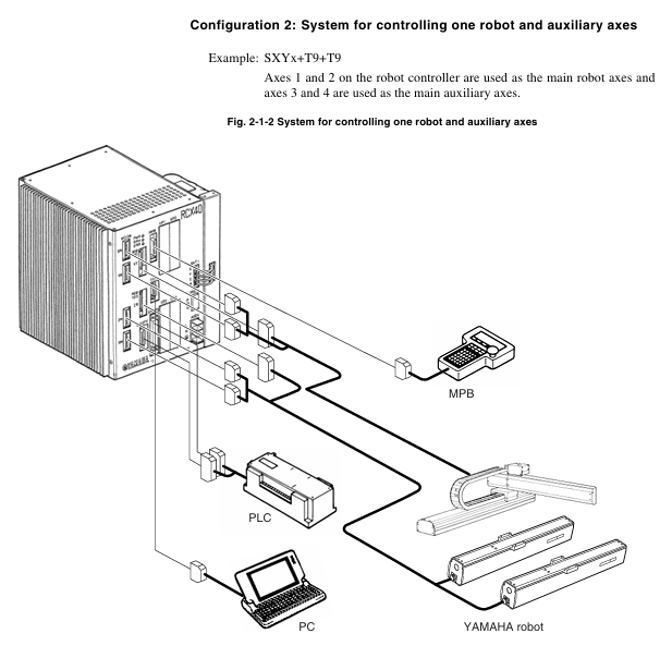
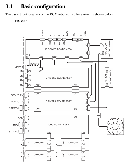
1. System configuration

Supports two core configurations: single robot control and single robot+auxiliary axis control (up to 4 axes).

The axis definition includes the main robot axis, main auxiliary axis, sub robot axis, and sub auxiliary axis, which can be switched through the MPB programming unit.

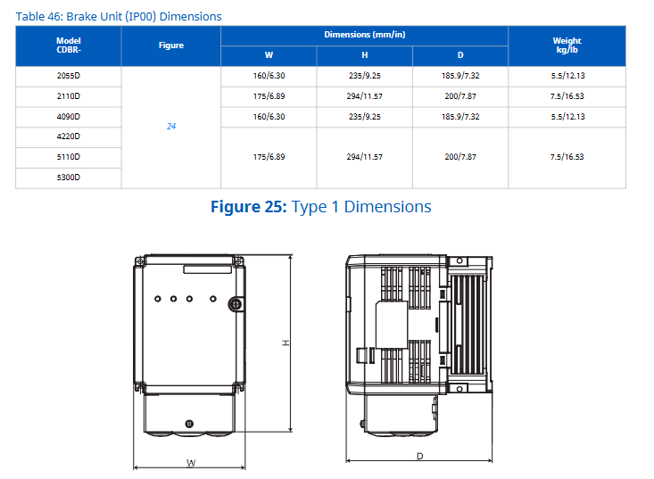
Optional devices include MPB programmer, expansion I/O board (up to 4 pieces), and regeneration unit, adapted to different system requirements.

2. Core functional highlights

Multi tasking function: Up to 8 tasks can be run simultaneously, supporting priority settings to improve system efficiency.

Robot Language: Adopting a high-level language similar to BASIC, in compliance with the industrial robot programming standard SLIM, supporting compilation and execution, and efficient programming.

Motion control: Supports Arch motion (freely set pick and place paths), 3D CP control (linear/arc interpolation motion), and reduces cycle time.

Easy maintenance: Software servo control achieves unit standardization, compatible with most YAMAHA robot models, simplifying maintenance and adjustment.

Compliance: Compliant with the Machinery Directive, Low Voltage Directive, and EMC Directive, supporting SAFE mode operation.

Installation and wiring specifications

1. Installation requirements

Environmental conditions: operating temperature of 0-40 ℃, storage temperature of -10-65 ℃, humidity of 35% -85% (no condensation), avoiding vibration, conductive dust, and corrosive gas environment.

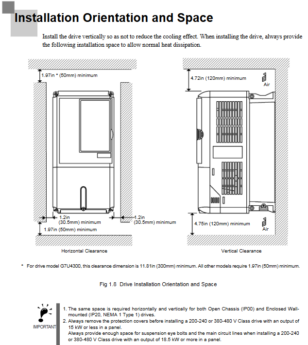
Installation space: Reserve at least 50mm gap on the top and sides, and at least 30mm gap on the back to ensure heat dissipation and ventilation.

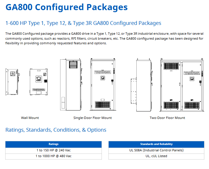
Installation method: Supports four installation methods: rubber foot pad installation, front and rear panel L-shaped bracket installation, and side L-shaped bracket installation.

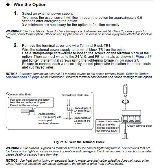
2. Key wiring points

Power connection: Supports AC200-230V single-phase input, requires correct connection of live wire (L), neutral wire (N), and ground wire, and voltage fluctuation should be controlled within ± 10%.

Cable layout: Robot cables need to be separated from power cables to avoid entanglement; When wiring, designated tools must be used to ensure the quality of crimping and welding.

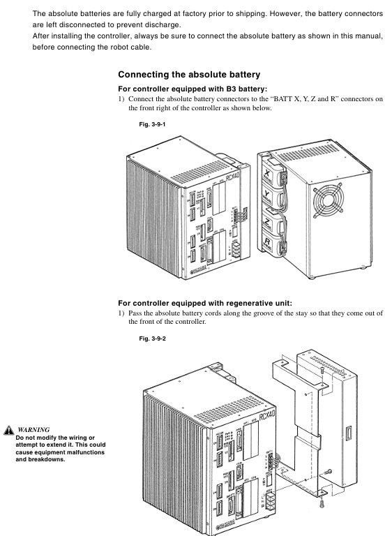
Absolute battery connection: The battery is not connected when it leaves the factory. After installation, the battery needs to be connected first and then the robot cable needs to be connected. The battery needs to be replaced regularly (about 1.5 years).

Emergency stop circuit: It is necessary to correctly connect the emergency stop signal through the SAFETY interface to ensure that the power is quickly cut off when triggered.

Operation mode and core operation

1. Main operating modes

Service mode: Only available in SAFE mode, used for maintenance within safety fences, limiting operating speed (≤ 3% maximum speed), and prohibiting automatic mode operation.

AUTO mode: executes robot programs, supports program reset, task switching, speed adjustment, breakpoint setting, and other functions.

Program mode: Create, edit, and manage robot programs, supporting operations such as program copying, deletion, renaming, and compilation.

MANUAL mode: Manually move the robot, perform point teaching, support absolute reset, coordinate setting, hand definition editing, etc.

SYSTEM mode: Configure system parameters, communication parameters, option functions, support data initialization, backup, and diagnosis.

UTILITY mode: handles auxiliary functions such as emergency stop cancellation, motor power switch, and execution level adjustment.

2. Key operational procedures

Absolute reset: When the origin is lost, it needs to be executed and supports single axis or full axis reset. Before resetting, ensure that the axis is in a safe position.

Program execution: Start the program in AUTO mode and debug it through STEP, SKIP, and NEXT.

Point teaching: In MANUAL mode, use the Jog key to move the robot to the target position and execute the TEACH command to save point data.

Data backup: Backup programs, parameters, point data, etc. to internal flash ROM through SYSTEM mode to avoid data loss.

I/O interface and communication

1. Standard I/O interface

It includes 10 dedicated inputs, 11 dedicated outputs, 16 universal inputs, and 8 universal outputs, and supports NPN/PNP specifications.

Specialized inputs include signals such as servo ON, program start, automatic mode switching, emergency stop, etc; Dedicated outputs include signals such as CPU status, servo status, alarm, program running status, etc.

2. Communication interface

Supports RS-232C interface, can connect to upper computer for data communication, and supports online command execution.

Communication parameters can be configured: baud rate (4800-57600bps), data bits (7/8 bits), stop bits (1/2 bits), parity bits (NONE/ODD/EVENT), etc.

Maintenance and troubleshooting

1. Key points of daily maintenance

Regularly check the absolute battery voltage (normal 3.50-4.3V), and if it is lower than 3.5V, it needs to be charged or replaced.

Regularly backup programs and parameters to avoid data loss caused by hardware failures.

Check if the cable connection is secure to avoid loosening and causing malfunctions.

Clean the controller’s cooling fan and fins to ensure good heat dissipation.

2. Fault handling

View error messages through the MPB screen and refer to the “Troubleshooting” section to locate the problem.

Common errors include loss of origin, low battery voltage, program syntax errors, abnormal I/O signals, etc., which require targeted handling.

Malfunctions that cannot be resolved on their own require contacting YAMAHA authorized dealers or technical support.

YASKAWA Z1000 series HVAC dedicated frequency converter

Applicable models:

200V level: 2.2~110kW (3~150HP);

400V level: 2.2~370kW (3~500HP);

Model identification: CIMR-ZU  A series.

Core positioning: A practical guide for engineering and technical personnel, covering the entire process from parameter initialization, motor debugging to troubleshooting, supporting multiple modes such as V/f control and PM motor open-loop vector control, and adapting to the dynamic adjustment needs of HVAC systems.

​Core functional framework

The document revolves around three core modules: parameter configuration, function implementation, debugging and maintenance. The core modules include parameter details, regular inspection and maintenance, and communication protocol configuration (BACnet/APOGEE FLN/Metasys N2/EMOBU/Modbus), forming a complete closed loop of “setup run monitoring maintenance”.

Core parameter configuration (classified by functional modules)

1. Initialize parameters (Group A)

The core is used for initial driver settings, including basic configurations such as language, control mode, parameter reset, etc.

A1-00 (Language Selection): Supports English, Japanese, French, Spanish, Portuguese, and does not reset this parameter during initialization.

A1-02 (Control mode selection): 0 (Induction motor V/f control, speed range 1:40), 5 (PM motor open-loop vector control, speed range 1:20).

A1-03 (Parameter Initialization): Supports multiple initialization modes such as user-defined, 2-wire/3-wire control, HVAC dedicated, OEM bypass, etc., and automatically returns to 0 after reset.

A1-04/A1-05 (password setting): A1-05 hides the parameter setting password, A1-04 unlocks by entering the password, and restricts the modification permission of core parameters (such as A1-01~A1-03).

2. Application Function Parameters (Group B)

Focus on core application functions such as operating mode, braking, speed search, PI control, etc., and adapt to HVAC load characteristics.

(1) Operation mode selection (b1 group)

B1-01 (AUTO mode frequency source): Supports four input methods: HOA keyboard, analog terminal, communication, and tab.

B1-02 (AUTO mode operation command): Optional control terminals, communication, and tab triggers. Selecting 3 when no tab is installed will trigger the oPE05 error.

B1-03 (stop mode): 0 (slope stop), 1 (free stop), 2 (DC injection brake stop), 3 (free stop with delay).

(2) PI control (b5 group)

Specially designed for closed-loop control of pressure, flow, and temperature in HVAC systems, with core parameters:

B5-01 (PI function enabled): 0 (disabled), 1 (PI output directly as frequency command), 3 (PI output combined with frequency command).

B5-02/B5-03 (Proportional/Integral Parameters): Proportional gain of 0.00~25.00, integration time of 0.0~3600s, can suppress overshoot or accelerate response speed.

B5-12 (PI feedback loss detection): Supports low/high feedback detection, can set alarms, faults, or only output signals to avoid sensor failures causing system loss of control.

(3) Energy saving function (b8 group)

B8-01 (Energy saving control enable): When enabled, automatically optimize the motor operating voltage to improve light load efficiency. PM motors should be used with caution.

3. Motor parameters (Group E)

The core parameter configuration covering induction motors and PM motors directly affects control accuracy.

E1 group (V/f mode setting): E1-03 selects V/f curve (15 presets+1 customization), suitable for constant torque, variable torque (fan/pump), high starting torque and other scenarios.

E2 group (induction motor parameters): requires input of motor rated current (E2-01), rated slip (E2-02), no-load current (E2-03), etc., supporting automatic tuning and automatic acquisition.

E5 group (PM motor parameters): Only visible when A1-02=5, stator resistance (E5-05), d/q-axis inductance (E5-06/E5-07), induced voltage constant (E5-09/E5-24), etc. need to be set.

4. Protection function parameters (L group)

Comprehensively ensuring the safety of drivers, motors, and systems, with core components including:

Motor protection (L1 group): L1-01 selects overload protection type (general motor/PM motor), supports PTC thermistor connection (L1-03~L1-05) to detect motor temperature.

Power protection (L2 group): L2-01 is configured with instantaneous power failure response strategy, and L2-05 is set with undervoltage detection level (default 190V for 200V level, default 380V for 400V level).

Lock rotor protection (L3 group): Install lock rotor protection during acceleration, deceleration, and operation to avoid motor overload or overvoltage faults.

Fault restart (L5 group): L5-01 sets the number of automatic restarts (0-10 times), supports automatic recovery after overcurrent, overload, overvoltage and other faults, and the lifting application is disabled.

5. Terminal functional parameters (H group)

Configure digital/analog input/output terminals to achieve external signal interaction.

H1 group (digital input): 7-channel programmable terminals (S1~S7), supporting functions such as forward and reverse rotation, multi-stage speed, fault reset, emergency stop, etc., and can be configured with 2-wire/3-wire control logic.

H2 group (digital output): 3 relay outputs (M1-M2/M3-M4/M5-M6), which can map signals such as operating status, zero speed, fault, and consistent speed.

H3 group (analog input): 2 analog terminals (A1/A2), supporting 0~10V/4~20mA signals, configurable frequency command, PI feedback, torque detection level and other functions.

H4 group (analog output): 2 analog terminals (FM/AM), capable of outputting monitoring data such as frequency, current, power, etc., supporting gain/bias adjustment.

6. Communication parameters (H5/F6/F7 group)

Supports multiple industrial communication protocols and is compatible with building automation system integration.

Core protocols: BACnet, APOGEE FLN, Metasys N2, MEMOBU/Modbus;

Basic configuration: H5-01 (slave address), H5-02 (baud rate), H5-03 (checksum), which need to be unified with the upper computer;

Fault handling: F6-01 configuration communication fault driver behavior (shutdown/continue running/alarm).

Motor debugging (T group)

Obtain precise motor parameters through automatic tuning to ensure control performance.

1. Induction motor debugging (T1 group)

T1-01 selects tuning mode: 2 (static resistance detection), 3 (V/f energy-saving mode rotation tuning);

Pre input of motor rated power (T1-02), voltage (T1-03), current (T1-04) and other nameplate parameters is required, and after tuning, the E2 group parameters will be automatically updated.

2. PM motor debugging (T2 group)

T2-03 Select motor type (0=IPM motor, 1=SPM motor);

T2-18 starts tuning and automatically calibrates key parameters such as stator resistance, inductance, and induced voltage constant, ensuring that the motor is unloaded.

Monitoring parameters (U group)

Real time viewing of drive operation status, fault records, and maintenance information, core categories:

U1 group (operating status): output frequency (U1-02), output current (U1-03), DC bus voltage (U1-04), etc;

U2/U3 group (fault tracing): record parameter snapshots (such as current, frequency) and historical fault lists (up to multiple records can be stored) when faults occur;

U4 group (maintenance monitoring): cooling fan running time (U4-03), percentage of capacitor life (U4-05), pre charge relay life (U4-07), etc. If it is less than 20%, it needs to be replaced in advance;

U5 group (PI monitoring): PI set values, feedback values, output values, etc., facilitate closed-loop control optimization.

Regular inspection and maintenance

1. Safety regulations

After power failure, wait for the capacitor to discharge (DC bus voltage below 50V) before wiring or replacing components;

Do not remove the cover plate or touch the circuit board while it is powered on to avoid static electricity damaging the components.

2. Inspection cycle and content

(1) Daily inspection (daily)

Appearance: The driver/motor has no abnormal noise, odor, or vibration, and the cooling fan is running normally;

Display: No alarm code, stable parameters such as current and voltage;

Environment: Temperature (-10~+50 ℃), humidity (0~95% without condensation) meet the requirements, and there is no dust accumulation.

(2) Regular inspection (annually)

Electrical components: The wiring terminals are securely fastened, the insulation of the wires is not aged, the capacitors are not leaking or bulging;

Cooling system: The radiator is clean, the fan is not stuck, and the air duct is not blocked;

Function verification: No abnormal changes in parameters, protection functions (such as overload and overvoltage) triggered normally.

3. Replacement of vulnerable parts

Cooling fan: Replace it after running for 20000 hours or 5 years, and reset the o4-03 parameter after replacement;

HOA keyboard battery: The model is CR1220 lithium battery, with a lifespan of about 2 years. Replace it when “bAT” is displayed, and pay attention to the installation of the positive and negative poles;

Capacitors and relays: After 5-7 years of operation, the capacity/contact status needs to be checked, and if it is lower than 80% of the initial value, it should be replaced.

Communication Protocol Configuration (Core Protocol Summary)

1. MEMOBU/Modbus communication

Physical interface: RS-422/RS-485 (terminal R+/R -/S+/S -);

Core parameters: Slave address (H5-01:0~FFH), baud rate (H5-02:1200bps~115200bps), parity bit (H5-03: none/even/odd parity);

Function: Supports reading monitoring data, writing parameters, controlling start stop, and fault reset.

2. BACnet communication

Adapt to building automation systems and support BACnet MS/TP protocol;

Configuration parameters: F6-46 (baud rate), device object, analog input/output object mapping;

Function: Implement remote monitoring and control of the frequency converter by the upper computer, and support fault alarm uploading.

Compliance and Safety Tips

Safety level: Complies with UL 508C, CSA C22.2 No.14, CE LVD/EMC and other standards;

Prohibited scenarios: It is prohibited to use equipment that directly affects personal safety, such as medical, aviation, nuclear power, etc. The lifting application is disabled and automatically restarted due to malfunction;

Operation specifications: All wiring, parameter modification, and maintenance work must be carried out by authorized personnel, and the power-off discharge process must be strictly followed.

YASKAWA HV600&Z1000U series

Core classification of product family

Core positioning of product series, main application scenarios

HV600 basic series standard HVAC frequency converter, cost-effective priority for small and medium-sized fans and pumps, ordinary building automation

HV600 bypass series with manual/automatic bypass function, ensuring continuous operation of critical loads (such as fire fans, core cold water pumps)

HV600 redundant series dual machine redundant configuration ensures zero downtime for critical facilities such as data centers and hospitals

Z1000U Matrix Series Matrix Topology, High end HVAC Projects with Strict Harmonic Requirements for Low Harmonic and High Energy Efficiency

Core product technical specifications and performance characteristics

1. General performance parameters (HV600 series basic type)

Voltage and power range:

208~240V three-phase: 3~100HP, rated output current 7~273A;

480V three-phase: 3~250HP, rated output current 7~629A;

Core performance:

Overload capacity: 110%/60 seconds, 140%/2 seconds, 175% instantaneous;

Speed range: 40:1 (V/f control), maximum output frequency 400Hz;

Starting torque: up to 140% of rated torque within the range of 3~60Hz;

Built in functions: 5% incoming impedance, EMC filter (compliant with IEC 61800-3), PID closed-loop control, motor preheating, automatic fault restart.

2. Z1000U Matrix Series Advanced Features

Topology advantages: direct AC-AC conversion, no DC bus capacitance, harmonic distortion rate (TDD)<5%, power factor close to 1.0;

Power coverage: 208V three-phase 10~100HP, 480V three-phase 7.5~350HP;

Core highlights: MTBF (Mean Time Between Failures) reaches 28 years, built-in Eco Mode energy-saving mode, supports PM motor open-loop vector control, and has 6 preset speeds built-in.

3. Protection level and installation environment

Protection options: IP20/UL Type 1 (indoor control cabinet), IP55/UL Type 12 (dustproof and splash proof), IP55/UL Type 3R (outdoor rainproof);

Environmental requirements:

Working temperature: -10~+40 ℃ (IP55 model), -10~+50 ℃ (IP20 model, for reduced capacity use);

Humidity: 0%~95% without condensation, altitude ≤ 1000 meters (over altitude requires capacity reduction);

Vibration: 9.8m/s ² at 10-20Hz, 2.0-5.9m/s ² at 20-55Hz (depending on the power of the model).

HV600 Series Core Configuration Solution

1. Basic model (without bypass)

Core configuration: Standard Hand Off Auto LCD keyboard, LED status ring, real-time clock, built-in communication protocols such as BACnet, Modbus, Siemens APOGEE, etc;

Extension options: LonWorks/EtherNet/IP communication card, Bluetooth keyboard, remote installation bracket, dV/dT filter (suppresses voltage spikes and protects motor insulation);

Terminal function: 7-channel programmable digital input (24VDC), 3-channel programmable relay output, supporting 0~10V/4~20mA speed given signal.

2. Bypass configuration scheme (ensuring continuous operation)

(1) Narrow body bypass (H6BP/H6BN series)

Features: Compact structure, saves control cabinet space, supports UL Type 1/12 protection;

Power range: 208V 0.5~25HP, 480V 0.75~60HP;

Bypass function: Built in bypass contactor, electronic overload protection, 115V control transformer, supports seamless switching between driver and power frequency bypass.

(2) Fully enclosed bypass (H6B1/H6B2/H6B3 series)

Features: Fully enclosed enclosure design, suitable for harsh environments, supports UL Type 1/12/3R protection;

Power range: 208/240V 0.5~100HP, 480V 0.5~250HP;

Extended functions: optional circuit breaker (100kAIC), 3-contactor bypass, space heater (anti condensation), observation window keyboard.

3. Redundant drive scheme (H6R series)

Core design: Dual HV600 driver redundant configuration, supporting manual/automatic switching, ensuring no downtime for critical loads;

Power range: 480V 3~250HP;

Standard features: shared input/output wiring, independent fault detection, synchronous parameter replication, built-in damping control circuit.

Z1000U Matrix Series Configuration Scheme

1. Basic matrix model (Z1000U series)

Core advantages: low harmonic pollution (no need for additional filters), high energy efficiency (full speed efficiency of 98%, half speed efficiency of 96%), and electrolytic capacitor design (extended lifespan);

Communication and Control: Built in BACnet (BTL certification), Modbus, Siemens APOGEE protocol, supporting EtherNet/IP/LonWorks extension;

Protection function: 100kAIC short-circuit withstand, fan fault detection, over temperature and speed reduction, under voltage crossing (2 seconds).

2. Matrix bypass/configuration model

Bypass model (Z1D1/Z1D2/Z1D3 series): with power frequency bypass function, UL Type 1/12/3R protection, 480V 7.5~350HP;

Configuration models (Z1E1/Z1E2/Z1E3 series): customizable input circuit breakers, output reactors, speed potentiometers, suitable for complex HVAC systems.

Key accessories and expansion options

1. Electrical accessories

Reactor: Input reactor (1.5%/3% impedance, harmonic suppression), output reactor (3% impedance, extended cable length);

Filter: dV/dT filter (UFI series, voltage spike<1000V, suitable for 1000 feet of cable);

Power and Control: 24VDC Control Power Unit (PS-U10L/PS-U10H), 200VA Control Transformer.

2. Operation and communication accessories

Keyboard and cables: LCD local keyboard (JVOP-KPLCB04AEB), Bluetooth wireless keyboard (supporting mobile APP operation), remote cable (1/3 meter);

Communication cards: EtherNet/IP dual port card (SI-EN3D), Modbus TCP/IP card (SI-EM3), LonWorks card (SI-W3);

Installation accessories: external heat sink kit, UL Type 1 end cap kit, independent mounting bracket.

Selection and Dimensional Data

1. Selection of core parameters

Suitable motor: Standard NEMA B-grade 4-pole motor, selected according to NEC 430.150 rated current;

Voltage matching: strictly corresponding to voltage levels of 208/240/480V, allowing for ± 10% voltage fluctuations;

Environmental adaptation: Select the model according to the protection level, temperature, and altitude. If it exceeds the specifications, it needs to be reduced in capacity for use.

2. Key dimension reference (example)

HV600 480V 10HP (HV60U4014CFA): Dimensions H14.1 × W4.9 × D8.6 inches, weight 15.4lb, heat dissipation loss 268W;

Z1000U 480V 75HP (CIMR-ZU4E0096AUA): Size H816 × W264 × D450mm, weight 63kg, heat dissipation loss 2005W;

Bypass model H6B1 480V 50HP (H6B1B065): Size H37.1 × W20.8 × D18.5 inches, weight 179lb.

YASKAWA Power Regenerative Unit R1000 Series

Core specifications of the product

Model coverage:

200V three-phase series: models 2A03P5~2A0105, suitable for motor power of 5~141HP, rated output current of 14~413A;

400V three-phase series: models 4A03P5~4A0300, suitable for motor power of 5~422HP, rated output current of 7~629A;

All models are designed for “Normal Duty” and optimized for energy regeneration scenarios with variable torque loads.

Core features: Supports 120 ° excitation control, MEMOBU/Modbus communication, PID closed-loop control, automatic fault restart, maintenance life monitoring, and complies with international standards such as UL 508C, IEC/EN 61800-5-1, as well as CE and RoHS compliance requirements.

Receiving and unboxing inspection

1. Safety precautions

It is prohibited to transport equipment through the front cover or terminal cover to avoid damage caused by the main body falling;

When handling equipment and circuit boards, it is necessary to follow the electrostatic discharge (ESD) process to prevent circuit damage.

2. Model and nameplate verification

Key information on the nameplate: model (such as CIMR-RU2A0073AAA), rated capacity, input/output specifications, software version, serial number, and place of origin (Japan);

Model interpretation: Taking “CIMR-RU2A0073AAA” as an example, “RU” represents the R1000 series, “2A” is the 200V level, “0073” is the rated output capacity code, and “AAA” is the standard configuration.

3. Classification of enclosure types

IP20/UL Type 1: Suitable for indoor wall mounted or control cabinet installation, retaining IP20 protection even after removing the top protective cover;

IP00/Open Type: It needs to be installed inside a protective panel, without additional shell protection, and relies on external environmental isolation.

Mechanical Installation: Environmental Requirements and Operating Standards

1. Installation environment requirements

Specific requirements for environmental dimensions: Remarks

Temperature IP00 model: -10~+50 ℃; IP20 model: -10~+40 ℃ overheating requires capacity reduction to avoid severe temperature fluctuations

Humidity ≤ 95% RH, no condensation to prevent moisture and short circuit of the circuit board

Altitude ≤ 1000 meters (without capacity reduction); 1000~3000 meters: For every 100 meters increase, the capacity is reduced by 1%. At high altitudes, the heat dissipation capacity needs to be evaluated

Vibration low-power models (2A03P5~2A0053, etc.): 10-20Hz (9.8m/s ²), 20-55Hz (5.9m/s ²); High power models (2A0073~2A0105, etc.): 20~55Hz (2.0m/s ²) Avoid direct contact with vibration sources

The surrounding environment should be free of dust, oil mist, metal debris, corrosive gases, and direct sunlight. Installation on flammable surfaces or placement of flammable materials is prohibited

2. Installation method and spacing requirements

Installation direction: Only supports vertical installation. Tilting can cause poor heat dissipation and damage to internal components.

Single installation spacing:

Up and down direction: at least 120mm (heat dissipation space);

Left and right direction: at least 30mm (wiring and heat dissipation);

Rear: It should be tightly attached to the enclosed surface to avoid the dispersion of cooling airflow.

Side by side installation (with drive):

Ordinary side by side: minimum spacing of 50mm, top aligned;

Tightly side by side (only for low-power models 2A03P5~2A0028, etc.): spacing of 2mm, parameter L8-35=1 needs to be set, while considering capacity reduction.

3. Precautions for lifting and protection

High power models (2A0073, 2A0105, etc.) are equipped with lifting rings and are only used for temporary installation. Long term suspension is prohibited;

When lifting vertically, it is necessary to first fix the front cover, terminal block and other components. The vibration/impact during suspension should not exceed 1.96m/s ², and flipping or leaving unattended is prohibited.

Electrical installation: wiring specifications and safety requirements

1. Main circuit wiring (prevention and control of core risk points)

Terminal differentiation:

Input terminals (R/L1, S/L2, T/L3): connected to three-phase power supply, matched with equipment voltage level (200V level connected to 200~240V, 400V level connected to 380~480V);

Output terminals (+, -): Connect to the DC bus of the driver, be careful not to reverse the positive and negative poles;

Voltage detection terminals (r1/11, l/21, t1/31): detect the phase sequence and voltage of the input power supply, and take power from the primary side of the power coordination reactor.

Wiring requirements:

Wire specifications: Select according to the rated current of the model. For example, 2A03P5 uses 14AWG (American standard) or 3.5mm ² (European standard) wire, 4A0300 uses 300kcmil wire, and circular crimping terminals are required;

Tightening torque: M4 screws 2.1~2.3N · m, M8 screws 5.4~6.0N · m, excessive tightening may damage the terminals;

Grounding: Independently grounded, not sharing grounding wire with high current equipment such as welding machines; Grounding resistance of 200V level ≤ 100 Ω, 400V level ≤ 10 Ω.

2. Control circuit wiring (anti-interference and functional configuration)

Digital input (S1~S8):

Support sinking/sourcing mode, switched through SC-SP/SC-SN jumper, default sinking mode;

Default functions: S1 (forced operation), S2 (automatic operation), S3 (external fault), S4 (fault reset), customizable through H1 series parameters.

Analog inputs (A1~A3):

A1/A3 default voltage input (0~10V/-10~10V), A2 default current input (4~20mA), switched through DIP switch S1;

For signal assignment, it is necessary to set the gain (H3-03/H3-07/H3-11) and bias (H3-04/H3-08/H3-12) to match the signal range.

Communication interfaces (R+, R -, S+, S -):

Supports RS-422/RS-485 for MEMOBU/Modbus communication, with the maximum transmission distance being related to the baud rate (up to 115.2kbps);

The terminal resistor needs to be enabled at the end of the bus (DIP switch S2 set to ON), and the communication line needs to be wired separately from the main power line.

3. Handling of special wiring scenarios

Long cable wiring: When the length of the control circuit analog signal line is ≤ 50 meters, and the main circuit cable is>50 meters, the carrier frequency should be reduced to avoid leakage current flowing through the large trigger protection;

12 pulse rectification configuration: The 4A0930/4A1200 models require the removal of jumper wires such as R/L1-R1/L11, and an external 3-winding transformer.

Start programming and operation: from parameter setting to trial run

1. Use of digital operator (core control interface)

Button functions:

RUN/STOP: Local start/stop, with the STOP key having the highest priority;

LO/RE: Switch between local/remote control, only operable during shutdown;

F1/F2: Switch display data/help menu, ESC returns to the previous level, ENTER confirms parameters.

Display interpretation:

Status display: “Rdy” (ready), “FWD/REV” (forward/reverse), ALM light (alarm/fault);

Monitoring interface: can view parameters such as DC bus voltage (U1-52), input current (U1-55), power (U1-57), etc.

2. Core parameter configuration (classified by application scenario)

(1) Basic initialization

Parameter A1-03 (initialization parameter):

0: No initialization;

1110: User defined initialization;

2220: 2-wire control initialization;

3330:3 wire system control initialization;

5550: oPE04 fault reset.

(2) Operation mode and control configuration

B1-02 (run command selection): 0 (numeric operator), 1 (numeric input), 2 (communication), 3 (tab);

C7-16 (minimum running time): In forced running mode, set the minimum holding time from start to stop (default 1.00 seconds);

L5-01 (number of fault restarts): 0-10 times, supports automatic restarts after overcurrent, overvoltage and other faults.

(3) Protection parameter configuration

L2-05 (undervoltage detection level): default 190V for 200V level, default 380V for 400V level, adjustable as needed;

L8-02 (overheating alarm level): default 85~140 ℃ (random variation), exceeding this temperature triggers an oH alarm;

L8-35 (installation method selection): 0 (IP00 model), 1 (tightly arranged), 2 (IP20 model), 3 (external heat sink).

3. Trial operation process (phased verification)

(1) No load trial operation

Step: Disconnect the load → Set as local control → Set low frequency (such as 6Hz) → Start the equipment → Check the motor direction, vibration, and current (should be 50% lower than the rated current) → Gradually increase the frequency to the rated value and observe the stability of operation.

(2) Test run with load

Preparation: Connect the load, confirm that the emergency stop circuit is effective, and check the PID feedback signals (such as pressure and flow sensors);

Operation: Start from low frequency (such as 20Hz), monitor input current (U1-55), DC bus voltage (U1-52), adjust PID parameters (b5-02 proportional gain, b5-03 integration time) to optimize response speed.

Troubleshooting and maintenance: ensuring long-term stable operation

1. Common faults and solutions

Possible causes and solutions for fault codes

OC (overcurrent) motor short circuit/insulation damage, short acceleration and deceleration time, load blockage check motor winding, extend acceleration and deceleration time, reduce load or increase model size

OV (overvoltage) input voltage is too high, deceleration is too fast, brake resistor is not connected, check power supply, prolong deceleration time, install brake resistor

OL2 (overload) load exceeds rated torque, excessive regenerative energy reduces load, optimizes regenerative energy distribution, and replaces high-capacity models

CE (communication error) loose communication line, mismatched baud rate, noise interference check wiring, unified communication parameters, strengthened shielding and grounding

EF3 (external fault S3) S3 terminal wiring error, external device fault verification H1-03 parameter setting, troubleshooting external device faults

2. Regular maintenance plan

(1) Daily inspection (daily)

Appearance: No abnormal noise, odor, or vibration, and the cooling fan is running normally;

Display: No alarm code, stable parameters such as current and voltage;

Environment: Confirm that the temperature and humidity meet the installation requirements and there is no dust accumulation.

(2) Regular maintenance (by cycle)

Maintenance project cycle operation requirements

Check the blade wear of the cooling fan after running for 20000 hours or 10 years, replace it with a fan of the same model, and reset the parameter o4-03

Measure the capacitance of the main circuit capacitor after 5-7 years of operation. If it is lower than 80% of the initial value, it needs to be replaced. Monitor the lifespan through U4-05

Check the torque of the main and control circuit terminals every 6 months to prevent looseness and heating during terminal tightening

Clean the radiator with compressed air every 3 months after power failure to avoid clogging the air duct

3. Maintain monitoring function

Parameters U4 series: U4-03 (fan running time), U4-04 (fan life percentage), U4-05 (capacitor life percentage), U4-06 (soft charging relay life). If it is less than 20%, it needs to be replaced in advance.

Peripheral equipment and communication configuration

1. Standard configuration and peripheral equipment

Required equipment: power coordination reactor, current suppression reactor, fuse (model needs to be matched according to the model);

Optional devices: 24V power supply (PS-A10LB/HB), USB replication unit (JVOP-181), LED operator (JVOP-182), communication tab (MECHATROLINK-II, CC Link, etc.).

2. MEMOBU/Modbus communication configuration

Communication parameters:

H5-01 (slave address): 0~FFH, default 1FH, ensure unique address;

H5-02 (baud rate): 0 (1200bps)~8 (115200bps), default 3 (9600bps);

H5-03 (checksum): 0 (no checksum), 1 (even checksum), 2 (odd checksum), default 0.

Communication function: Supports reading monitoring data, writing parameters, controlling operation/stop, fault reset, and can be remotely controlled through PLC or upper computer.

YASKAWA AC Drive P1000 Industrial Fan

Core positioning: Quick Start Guide, to be used in conjunction with the P1000 Series AC Drive Technical Manual (SIEPYAIP1U01). The former focuses on basic installation and trial operation, while the latter provides detailed parameters and advanced feature explanations.

Core specifications of the product

Model coverage:

200 V Class (three-phase): Models 2A0004~2A0415, suitable for motor power of 0.75~175 HP, rated output current of 3.5~415 A;

400 V Class (three-phase): Models 4A0002~4A1200, suitable for motor power of 0.75~1000 HP, rated output current of 2.1~1200 A;

600 V Class (three-phase): models 5A0003~5A0242, suitable for motor power of 1~250 HP, rated output current of 2.7~242 A;

All models are labeled with “ND” (Normal Duty) and are designed specifically for variable torque loads on fans and pumps.

Core features: Support preset application parameters, Auto Tuning, PID closed-loop control, EZ sleep/wake energy-saving function, multiple braking methods (DC injection braking, dynamic braking), in compliance with UL, cUL, CE, RoHS 2 and other certification standards.

Mechanical Installation: Environmental Requirements and Operating Standards

1. Installation environment requirements (must be strictly followed)

Specific requirements for environmental dimensions: Remarks

Temperature IP20/NEMA 1 model: -10~+40 ℃; IP00/Open Type models: -10~+50 ℃. If the temperature exceeds+50 ℃, the capacity needs to be reduced to avoid severe temperature fluctuations

Humidity ≤ 95% RH, no condensation to prevent moisture and short circuit of the circuit board

Altitude ≤ 1000 meters (without capacity reduction); 1000-4000 meters: For every 1000 meters increase, the capacity decreases by 8%. In high-altitude areas, the heat dissipation capacity needs to be evaluated

Avoid direct contact with vibration sources at frequencies of 10-20Hz (9.8m/s ²) and 20-55Hz (5.9m/s ²)

The surrounding environment should be free of dust, oil mist, metal debris, corrosive gases, and direct sunlight. A clean environment is preferred, and suitable protective kits should be selected for harsh environments

2. Installation method and spacing requirements

Installation direction: Only supports vertical installation. Tilting installation can cause poor heat dissipation and damage to internal components.

Single installation spacing:

Up and down direction: at least 50mm (heat dissipation space);

Left and right direction: at least 30mm (wiring and heat dissipation);

Rear: It should be tightly attached to the enclosed surface to avoid the dispersion of cooling airflow.

Multiple units installed side by side:

Only low-power models (such as 2A0004~2A0081, 4A0002~4A0044) are supported, and the parameter L8-35=1 (Side by Side mode) needs to be set;

The minimum spacing is 2mm, but capacity reduction needs to be considered and aligned with the top of the model to facilitate fan replacement.

3. Precautions for lifting and protection

Use of lifting rings: Some high-power models (such as 2A0360, 4A0250~4A1200) are equipped with lifting rings, and vertical lifting is only used for temporary installation. Long term suspension is prohibited; The lifting of 4A0930/4A1200 requires a suspension angle of ≥ 50 ° to avoid overloading of the lifting ring.

Protection level maintenance: After removing the top protective cover or bottom conduit bracket of IP20/NEMA 1 models, only IP20 protection is retained and NEMA 1 certification is lost.

Electrical installation: wiring specifications and safety requirements

1. Main circuit wiring (prevention and control of core risk points)

Terminal differentiation:

Input terminals (R/L1, S/L2, T/L3): connected to a three-phase power supply, matching the voltage level of the frequency converter (such as 200V level connected to 200-240V, 400V level connected to 380-480V);

Output terminals (U/T1, V/T2, W/T3): connected to the motor, the phase sequence determines the motor direction, and reverse can exchange any two phases ();

Brake terminals (B1, B2): only connect brake resistors/brake units, strictly prohibit connecting other devices.

Wiring requirements:

Wire specifications: Choose according to the rated current of the model. For example, the 2A0004 model uses 14AWG wire for the main circuit, and the 4A1200 model uses 300kcmil wire, and requires the use of ring crimping terminals (UL/cUL certification requirements);

Tightening torque: M4 screws 1.2-1.5N · m, M8 screws 9.9-11N · m. Overtightening may damage the terminals;

Grounding: separate grounding, not sharing grounding wire with high current equipment such as welding machines; The cross-sectional area of the grounding wire for models 4A0414 and above is ≥ 10mm ² (copper) or 16mm ² (aluminum).

2. Control circuit wiring (anti-interference and functional configuration)

Digital input (S1~S8):

Support sinking/sourcing mode, switched through SC-SP/SC-SN jumper, default sinking mode;

Default functions: S1 (forward rotation), S2 (reverse rotation), S3 (external fault), S4 (fault reset), customizable through H1 series parameters.

Analog inputs (A1~A3):

A1/A3 default voltage input (0~10V), A2 default current input (4~20mA), switched through jumper S1;

For frequency setting, it is necessary to set the gain (H3-03/H3-07/H3-11) and bias (H3-04/H3-08/H3-12) to match the signal range (,).

Communication interfaces (R+, R -, S+, S -):

Supports RS-422/RS-485 for MEMOBU/Modbus communication, with the maximum transmission distance being related to the baud rate (up to 115.2kbps);

The terminal resistor (DIP switch S2 set to ON) needs to be enabled at the end of the bus.

3. Handling of special wiring scenarios

Long cable wiring (>50 meters): It is necessary to reduce the carrier frequency (C6-02), set it below 5kHz for 50-100 meters, and below 2kHz for>100 meters to avoid leakage current through large trigger protection (,).

12 pulse rectification (4A0930/4A1200): The jumper wires between R/L1-R1/L11, S/L2-S1/L21, and T/L3-T1/L31 need to be removed, and an external 3-winding transformer (,) needs to be connected.

Start programming and operation: from parameter setting to trial run

1. Use of digital operator (core control interface)

Button functions:

RUN/STOP: Local start/stop, with the STOP key having the highest priority;

LO/RE: Switch between local/remote control, only operable during shutdown;

ESC/ENTER: Return to the previous level/confirm parameters, long press ESC to return to the frequency setting interface ().

Display interpretation:

Status display: “Rdy” (ready), “FWD/REV” (forward/reverse), ALM light (alarm/fault);

Monitoring interface: can view parameters such as output frequency (U1-02), output current (U1-03), PID feedback (U5-01), etc.

2. Core parameter configuration (classified by application scenario)

(1) Basic initialization

Parameter A1-03 (initialization parameter):

0: No initialization;

2220-2 wire system control initialization (S1 forward rotation, S2 reverse rotation);

3330:3 wire system control initialization (S1 start, S2 stop, S5 forward and reverse);

8008~8011: Fan/pump preset (,).

(2) Motor and load adaptation

E2-01 (rated current of motor): It must be strictly set according to the motor nameplate, and will automatically update after automatic tuning;

C1-01/C1-02 (Acceleration/Deceleration Time 1): It is recommended to set the fan/pump load to 60-90 seconds to avoid water/air flow impact;

B1-03 (shutdown mode): default “ramp shutdown” (C1-02), high inertia load can choose “DC injection braking” (b2-02 braking current needs to be set).

(3) Fan/pump specific function

PID control: parameter b5-01=1 enables PID, A2 terminal defaults to feedback signals (such as pressure and flow sensors), b5-19 sets PID setpoint (,);

EZ sleep/wake-up: parameter b5-89=1 enabled, b5-92 sets sleep frequency (such as 0Hz), b5-94 sets wake-up threshold to avoid frequent start stop and save energy (,);

Blockage protection: L3-01=1 (acceleration blockage protection), L3-04=1 (deceleration blockage protection), to avoid overload triggering overcurrent (,).

3. Auto Tuning

Function: Automatically detect motor parameters (stator resistance, leakage inductance, etc.), optimize V/f curve and control accuracy, recommended for first-time use.

Operation steps:

Set T1-01=2 (static tuning, measuring line resistance) or T1-02=3 (dynamic tuning, motor rotation);

Enter the motor nameplate parameters (T1-02 power, T1-04 current, T1-06 pole count, etc.);

Press the RUN key to start tuning, and after completion, display “Tune Successful” (,).

Attention: Dynamic tuning requires disconnecting the motor load to ensure that the motor can rotate freely; Long cables (>50 meters) require static tuning first.

4. Trial operation process (phased verification)

(1) No load trial operation

Step: Disconnect the motor from the load → Set as local control → Start at a given frequency of 6Hz → Check the motor direction, vibration, and current (should be 50% lower than the rated current) → Gradually increase the frequency to the rated value and observe the stability of operation (,).

(2) Test run with load

Preparation: Connect the load and confirm that the emergency stop circuit is effective;

Operation: Starting from low frequency (such as 20Hz), monitor the output current (U1-03), PID feedback (such as whether the pressure is stable), adjust PID parameters (b5-02 proportional gain, b5-03 integration time) to optimize response speed (,).

Troubleshooting and maintenance: ensuring long-term stable operation

1. Common faults and solutions

Possible causes and solutions for fault codes

OC (overcurrent) 1. Motor short circuit/insulation damage; 2. The acceleration and deceleration time is too short; 3. Load blockage 1. Check the motor winding; 2. Extend C1-01/C1-02; 3. Reduce load or increase model size

OV (overvoltage) 1. Input voltage is too high; 2. Slow down too quickly; 3. The braking resistor is not connected. 1. Check the power supply; 2. Extend C1-02 or activate stall protection; 3. Install the braking resistor

OL1 (motor overload) 1. E2-01 is set too low; 2. The load exceeds the rated torque of the motor. 1. Correct E2-01; 2. Verify the load or replace the large motor

FbL (PID feedback low) 1. Sensor disconnection; 2. Feedback signal not connected correctly. 1. Check the sensor and wiring; 2. Confirm the function of terminal A2 (H3-10=B)

2. Regular maintenance plan

(1) Daily inspection (daily)

Appearance: No abnormal noise, odor, or vibration;

Display: No alarm code, stable current/frequency;

Heat dissipation: The fan is running normally and there is no dust blockage.

(2) Regular maintenance (by cycle)

Maintenance project cycle operation requirements

Check the blade wear of the cooling fan after running for 20000 hours and replace it with a fan of the same model

Measure the capacitance of the main circuit capacitor after 5-7 years of operation. If it is lower than 80% of the initial value, it needs to be replaced

Check the torque of the main circuit terminals every 6 months to prevent looseness and heating during terminal tightening

Clean every 3 months by blowing compressed air to remove dust from the radiator (operated after power outage)

3. Maintain monitoring function

Parameters U4-01~U4-04: Display cooling fan, main capacitor IGBT、 The remaining lifespan (percentage) of the control circuit capacitor should be replaced in advance if it is less than 20%.

YASKAWA FP605 series industrial fan pump dedicated driver

Product core positioning

FP605 is a specialized driver designed for industrial fans and pumps, with core advantages focused on flexibility, sustainability, and ease of use

Flexible adaptation: Supports control of induction motors, permanent magnet motors, and synchronous reluctance motors, adapts to multiple installation environments, is compatible with mainstream industrial communication protocols, and has a simple installation design.

Sustainable operation: Integrated functional safety (STO), using environmentally friendly materials, with a 10-year maintenance free design, built-in 5% voltage divider or 3% positive bus DC link reactor, reducing harmonic interference.

Strong usability: equipped with a high visibility status ring, 32 character LCD touch keyboard, supporting Bluetooth wireless operation and DriveWizard Mobile mobile app management, providing preset parameters for pump applications, and efficient debugging.

Product Model System and Core Specifications

1. Model coding rules (taking “FP65U4005AFA” as an example)

Encoding segment meaning optional values/description

FP65 product series fixed prefix (FP605 series)

U region code U=Americas region

4 voltage levels 2=240V three-phase, 4=480V three-phase

005 rated output current corresponds to rated output current (unit: A, here it is 5A)

A environmental specification A=standard specification

F chassis type F=IP20/UL Type 1, B=IP20/protective chassis, V=IP55/UL Type 12, T=IP55/UL Type 12 with switch, W=flange installation (back of Type 12)

A EMC filter A=No built-in EMC filter (compliant with C2 level standards)

2. Classification of core specifications (by voltage level)

(1) 240V three-phase input (IP20/IP55 multi chassis type)

Rated output chassis frame IP20/UL Type 1 model IP20/protective chassis model IP55/UL Type 12 model IP55/UL Type 12 with switch model flange Type 12 back model

Power (HP) Current (A) FP65U… AFA FP65U… ABA FP65U… AVA FP65U… ATA FP65U… AWA

3 10.6 1 2011AFA – 2011AVA 2011ATA –

5 16.7 1 2017AFA – 2017AVA 2017ATA –

7.5 24.2 2 2024AFA – 2024AVA 2024ATA –

10 30.8 2 2031AFA – 2031AVA 2031ATA –

15 46.2 3 2046AFA – 2046AVA 2046ATA –

20 59.4 3 2059AFA – 2059AVA 2059ATA –

25 74.8 4 2075AFA – 2075AVA 2075ATA –

30 88 4 2088AFA – 2088AVA 2088ATA –

40 114 4 2114AFA – 2114AVA 2114ATA –

50 143 6 2143AFA – 2143AVA 2143ATA –

60 169 6 2169AFA – 2169AVA 2169ATA –

75 211 9 – 2211ABA – – 2211AWA

100 273 9 – 2273ABA – – 2273AWA

125 343 10 – 2343ABA – – 2343AWA

150 396 10 – 2396ABA – – 2396AWA

(2) 480V three-phase input (IP20/IP55 multi chassis type)

Rated output chassis frame IP20/UL Type 1 model IP20/protective chassis model IP55/UL Type 12 model IP55/UL Type 12 with switch model flange Type 12 back model

Power (HP) Current (A) FP65U… AFA FP65U… ABA FP65U… AVA FP65U… ATA FP65U… AWA

3 4.8 1 4005AFA – 4005AVA 4005ATA –

5 7.6 1 4008AFA – – – –

7.5 11 1 4011AFA – 4011AVA 4011ATA –

10 14 1 4014AFA – 4014AVA 4014ATA –

15 21 2 4021AFA – 4021AVA 4021ATA –

20 27 2 4027AFA – 4027AVA 4027ATA –

25 34 2 4034AFA – 4034AVA 4034ATA –

30 40 3 4040AFA – 4040AVA 4040ATA –

40 52 3 4052AFA – 4052AVA 4052ATA –

50 65 3 4065AFA – 4065AVA 4065ATA –

60 77 4 4077AFA – 4077AVA 4077ATA –

75 96 4 4096AFA – 4096AVA 4096ATA –

100 124 4 4124AFA – 4124AVA 4124ATA –

125 156 6 4156AFA – 4156AVA 4156ATA –

150 180 9 – 4180ABA – – 4180AWA

200 240 9 – 4240ABA – – 4240AWA

250 302 9 – 4302ABA – – 4302AWA

300 361 10 – 4361ABA – – 4361AWA

350 414 10 – 4414ABA – – 4414AWA

400 477 11 – 4477ABA – – 4477AWA

450 515 11 – 4515ABA – – 4515AWA

500 590 11 – 4590ABA – – 4590AWA

600 720 11 – 4720ABA – – 4720AWA

3. Protection level and installation adaptation

IP20/UL Type 1: Suitable for clean environments, supports installation inside cabinets (with built-in/external heat sinks) and without cabinets (requires Type 1 adapter).

IP55/UL Type 12: Suitable for limited dust environments, can be directly wall mounted, and some models have switch designs.

Flange Type 12 Back: Suitable for dirty external environments, the heat sink is externally installed inside the Type 12 cabinet without the need for an additional adapter.

Core selection plan (including capacity reduction and installation)

1. Single phase input derating rules

When a three-phase driver is used for single-phase input scenarios, it needs to be reduced in capacity. The core reduction data is as follows (taking 240V/480V as an example):

(1) 240V single-phase input (without reactor)

Driver model (FP65U) Motor power (HP) Motor rated current (A) Output capacity (kVA) Input current (A)

2011 1.0 4.6 1.7 7.4

2017 2.0 7.5 3.2 14

2024 3.0 10.6 4.6 20

2031 3.0 10.6 4.6 20

2046 5.0 17.0 7.3 32

2059 7.5 24 10.3 45

(2) 480V single-phase input (without reactor)

Driver model (FP65U) Motor power (HP) Motor rated current (A) Output capacity (kVA) Input current (A)

4005 1.0 2.1 1.5 3.4

4008 2.0 3.4 2.8 6.1

4011 3.0 4.8 4.1 9.0

4014 3.0 4.8 4.1 9.0

4021 3.0 4.8 4.1 9.0

Solution: Capacity reduction can be avoided through a “single-phase converter (SPC)”, such as the 240V 20HP single-phase converter kit (SPBC-240-20HP), which supports a maximum motor load of 20HP, an input current of 79A, and requires a DC link reactor (URX000530).

2. Installation method and compatible accessories

(1) Classification of installation methods

Installation method, applicable scenarios, key requirements, and compatible accessories

The heat sink inside the cabinet is built into a clean room, with sufficient space and no need for additional brackets. The cabinet needs ventilation-

External cooling fins inside the cabinet are installed in a clean room. Due to limited cabinet space, external cooling fin adapters ZPSA series (UL Type 1) and ZPSD series (IP55/UL Type 12) are required

Directly install inorganic cabinets in clean rooms, without dedicated cabinets requiring Type 1 adapters to convert protection level 900-192-121 series Type 1 adapters

Type 12 flange with external dusty heat sink installed on the back, compatible with Type 12 cabinet AWA suffix flange models

(2) Installation accessory selection

Type 1 adapter: 240V 2211ABA model compatible with 900-192-121-009480V 4361ABA model compatible with UUX001700.

External heat sink adapter: 240V 2011AFA model compatible with ZPSA-600-EH1-FR1 (UL Type 1), ZPSD-600-EH12-FR1 (IP55/UL Type 12).

DIN rail installation: Only supports low-power compact models and requires a dedicated DIN rail kit.

Key components and power optimization options

1. Operation and communication accessories

(1) Operation panel and cables

Type, Model, and Function Description of Accessories

Standard LCD panel JVOP-KPPLCA04MEB local/remote control, parameter setting, operation monitoring

Bluetooth LCD panel JVOP-KPLCC04MBB supports wireless operation with DriveWizard Mobile mobile app

Remote installation cables UWR0051 (1 meter), UWR0052 (3 meters) panel remote installation extension cable

PC communication cable UWR01258 (3 meters) PC and driver USB communication, parameter upload/download

Android device cables UWR01516-B (Micro-B), UWR01516-C (Type-C) Android device connection driver USB port debugging

(2) Communication tab

Model Communication Protocol Function Description

JOHB-SMP3-MA Multi Protocol Ethernet supports EtherNet/IP, Modbus TCP/IP, PROFINET, EtherCAT

SI-P3 PROFIBUS-DP compatible with PROFIBUS-DP network

SI-N3 DeviceNet compatible with DeviceNet network

SI-W3 LonWorks Building Automation Communication

SI-B3 BACnet MSTP Building Automation Network Communication

SI-S3 CANopen CAN bus communication

2. Power optimization options (reactors, filters)

(1) AC input reactor (1.5%/3% impedance)

Used to improve input power factor, reduce harmonics, and protect drivers (recommended for power capacity>600kVA), example selection:

Voltage level driver model 1.5% impedance (open) 1.5% impedance (closed) 3% impedance (open) 3% impedance (closed)

240V 2011AFA URX000315 URX000418 URX000307 URX000413

240V 2017AFA URX000319 URX000420 URX000311 URX000415

480V 4005AFA URX000299 URX000410 URX000300 URX000503

480V 4011AFA URX000307 URX000413 URX000308 URX000414

(2) AC output reactor (3% impedance)

Used to reduce transient interference on the load side and adapt to long cable routing scenarios. Example selection:

Voltage level driver model Open model Closed model

240V 2011AFA 05P00620-0134 05P00620-0032

240V 2017AFA 05P00620-0136 05P00620-0036

480V 4005AFA 05P00620-0025 05P00620-0029

480V 4011AFA 05P00620-0135 05P00620-0033

(3) Single phase converter (SPC)

System kit model Maximum motor load (HP) Input current (A) Output DC current (A) Core components

SPBC-240-20HP 20 79 57 SPBC-2015AAA converter+URX000530 reactor

SPBC-240-30HP 30 116 84 SPBC-2022AAA converter+URX000531 reactor

SPBC-480-30HP 30 58 42 SPBC-4022AAA converter+URX000534 reactor

SPBC-480-125HP 125 234 170 SPBC-4093AAA converter+URX000529 reactor

Size and weight

1. IP20/UL Type 1 models (AFA suffix)

Chassis frame height (in), width (in), depth (in), compatible model example

1 14.1 4.9 8.6 2011AFA、4005AFA

2 17.6 4.9 9.2 2024AFA、4021AFA

3 20.1 7.9 9.3 2046AFA、4040AFA

4 21.3 10 10.4 2075AFA、4077AFA

6 30.5 12.3 15.7 2143AFA、4156AFA

2. IP55/UL Type 12 models (AVA suffix)

Chassis frame height (in), width (in), depth (in), compatible model example

1 14.1 4.9 9.0 2011AVA、4005AVA

2 17.6 4.9 9.6 2024AVA、4021AVA

3 20.1 7.9 9.7 2046AVA、4040AVA

4 21.3 10 10.7 2075AVA、4077AVA

6 30.14 14.26 16.14 2143AVA、4156AVA

3. Protective casing models (ABA suffix)

Chassis frame height (in), width (in), depth (in), compatible model example

9 27.6 12.3 16.5 2211ABA、4180ABA

10 31.5 17.3 18.6 2343ABA、4361ABA

11 44.9 20.1 18.9 4477ABA、4720ABA

Environmental and safety regulations

1. Environmental requirements

Temperature: IP20/flange model -10~+50 ℃, Type 1 kit installation -10~+40 ℃, up to+60 ℃ (capacity reduction required);

Humidity: ≤ 95% RH (no condensation);

Altitude: ≤ 1000 meters without capacity reduction, with a capacity reduction of 8% for every 1000 meters increase between 1000-4000 meters;

Vibration: 10-20Hz (9.8m/s ²), 20-55Hz (5.9m/s ²);

Protection level: IP20/UL Type 1, IP20/protective type IP55/UL Type 12、 Back of flange type 12.

2. Safety certification and standards

Certification: UL, cUL, CE, RoHS 2, WEEE, TUV SUD;

Functional safety: Safe Torque Off (STO), compliant with IEC 62061 SIL3, ISO 13849-1 PLe;

EMC standard: Built in reactor, compliant with EN 61800-3 C2 level requirements;

PCB coating: Complies with IEC 60721-3-3 Class 3C2 (chemical gases) and 3S2 (solid particles).

image.png

YASKAWA GA500 series AC micro driver

Core positioning and advantages of the product

Applicable scenarios: General in the industrial field, capable of precise control of induction motors, permanent magnet motors, and synchronous reluctance motors, supporting multiple application scenarios without the need for complex debugging.

Core advantage: Equipped with EZ Vector mode, it can adapt to all supported motor types without the need for comprehensive tuning; Easy installation, simple maintenance, strong system integration, more reliable machine design, can save time and costs.

Protection level: The standard model has an IP20 protection level (protective casing), suitable for clean environments.

Product model and specification system

1. Model coding rules

Taking “GA50U4004ABA” as an example, the meanings of each paragraph are as follows:

Product series: GA500; Region codes: U (Americas), M (Moisture resistant), S (Vibration resistant);

Voltage level: B (240V single-phase), 2 (240V three-phase), 4 (480V three-phase);

Type of chassis: B (IP20/protective type), J (no heat sink type); EMC filters: A (no built-in), E (built-in).

2. Classification of core specifications

Voltage type, power range, output current (regular/heavy load)

240V single-phase input 1/6~5HP (0.1~3.7kW) conventional: 1.2~12.2A; heavy load: 0.8~17.5A

240V three-phase input 1/6~30HP (0.1~22kW) conventional: 1.2~82A; heavy load: 0.8~75A

480V three-phase input 1/2~40HP (0.2~30kW) conventional: 1.2~60A; heavy load: 1.2~45A

3. Special model variants

Covering variants such as high-frequency output (2000Hz), anti vibration type, moisture resistant type, and no heat sink type, some variants (except for high-frequency output) have a delivery cycle of 16 weeks when there is no forecast order.

Core selection plan

1. Explanation of single-phase input derating

When a three-phase driver is used in a single-phase input scenario, it needs to be reduced in capacity. For example, the 240V three-phase 2001 model driver reduces the conventional power from 1/6HP to 1/8HP during single-phase input, which can be avoided by a single-phase converter. The power factor is close to 1, and the total harmonic distortion rate is less than 10%.

2. Installation method selection

The IP20 standard model supports three installation methods:

Installation inside an independent cabinet (with built-in heat sinks, no additional brackets required);

Installation inside an independent cabinet (with external heat sinks, requiring an external heat sink adapter);

Direct installation of inorganic cabinet (requires UL Type 1 adapter).

3、 Core selection plan (including capacity reduction and installation)

1. Single phase input derating rules

When a three-phase driver is used for single-phase input scenarios, it needs to be reduced in capacity. Taking the 240V three-phase model as an example, the core reduction data is as follows (partial excerpt):

Driver model (GA50U) without reactor (Open) without reactor (UL Type 1 closed) with reactor (AC input type)

Motor Power (HP) Current (A) Motor Power (HP) Current (A) Reactor Model Corresponding Power (HP)

2001 – – 1/8 0.61 URX000283 1/8

2002 1/8 0.61 1/4 1.16 URX000291 1/4

2004 1/4 1.16 1/3 1.52 URX000295 1/3

2006 1/3 1.52 1/2 2.20 URX000299 1/2

Solution: Capacity reduction can be avoided through a “single-phase converter (SPC)”, such as the 240V 20HP single-phase converter (SPBC-240-20HP), which supports a maximum motor load of 20HP and an input current of 79A. It needs to be paired with a DC link reactor (URX000530).

2. Installation method and adaptation requirements

The IP20 standard model supports three installation methods, which need to be selected according to the environment:

(1) Classification of installation methods

Installation method, applicable scenarios, key requirements, and compatible accessories

Method 1: Inside an independent cabinet (with built-in heat sinks) in a clean room with sufficient space and no need for additional brackets. The cabinet should be well ventilated-

Method 2: Inside an independent cabinet (with external heat sinks) in a clean room, if the cabinet space is limited, an external heat sink adapter should be selected according to the drive model. For example, the 240V single-phase B001 model is compatible with the ZPSA-GA50V1-1 external heat sink adapter (ZPSA series)

Method 3: Install the inorganic cabinet directly in the clean room, and all models without dedicated cabinets need to be equipped with UL Type 1 adapters. For example, the 240V single-phase B001 model is compatible with the ZBAA-GA50V1-1 UL Type 1 adapter (ZBAA series)

🔶 4-42 🔶 4-43 🔶 4-44 

(2) DIN rail installation adaptation

Only models with a width<170mm and a height<128mm are supported, such as 240V single-phase B002ABA compatible with ZPZ-GA50V1, B010ABA compatible with ZPZ-GA50V2, and high-power models (such as B018ABA) that require a dedicated kit (EZZ08122D) 🔶 4-237.

Key components and power optimization options

1. Installation and operation of accessories

(1) Operation panel and cables

Type, Model, and Function Description of Accessories

Standard LCD panel JVOP-KPPLCA04MEB without Bluetooth, supports parameter setting, operation monitoring, and fault reset

JVOP-KPLCC04MBB with Bluetooth LCD panel supports mobile APP control and requires remote cable

Remote installation of cables UWR0051 (1 meter) and UWR0052 (3 meters) for panel remote installation, extending the control distance

PC communication cable UWR01258 (3 meters) for USB communication between PC and driver, used for parameter upload/download

Android device cables UWR01516-B (Micro-B), UWR01516-C (Type-C) Android device connection driver USB port, supports debugging

🔶 4-170 🔶 4-186 

(2) Install adapters and shielding accessories

Example of accessory type and model for adaptation scenarios

Installation of UL Type 1 adapter ZBAA-GA50V1-1 (240V single-phase B001/B002) inorganic cabinet, converting IP20 to UL Type 1 protection

External heat sink adapter ZPSA-GA50V1-1 (240V single-phase B001/B002) for external installation of heat sinks, saving cabinet space

DIN rail adapter ZPZ-GA50V1 (240V single-phase B002) DIN rail quick installation, supports one click loading and unloading

Shielding clip kit ZHZ-GA50V1 (240V single-phase B002) for grounding and fixing the shielding layer of the shielded motor cable to reduce interference

🔶 4-204 🔶 4-222 🔶 4-239 

2. Power optimization options (reactors, filters, braking components)

(1) EMC filter

Used to suppress electrical noise on the input side, in compliance with EN 61800-3 C2 level requirements, classified by voltage:

Voltage type driver model example EMC filter model

240V single-phase B001A * * FS23638-10-07

240V three-phase 2001A * * FS23637-8-07

480V three-phase 4001A * * FS23639-5-07

🔶 4-281 🔶 4-283 

Size example: FS23638-10-07 (240V single-phase) measures 169 × 71 × 45mm and weighs 0.97lbs.

(2) AC reactor (input/output)

3%/5% impedance, improve power factor, reduce harmonics, separate amplifier and UL Type 1 enclosed type according to installation form, such as 240V three-phase 2001 model:

3% input reactor (open type): URX000283;

3% input reactor (enclosed type): URX000652;

5% input reactor (open type): URX000284;

5% input reactor (enclosed type): URX000585;

Power loss: URX000283 (240V three-phase) has a power loss of 4.8W, dimensions of 114.3 × 94 × 38.1mm, and a weight of 0.9lbs.

(3) Braking resistor and regeneration unit

Example of brake type duty cycle adaptation scenario model

Dynamic braking resistor 3% low-frequency braking, compatible with R7508 for ordinary conveyor belt 240V single-phase B001 model

Dynamic braking resistor with 10% medium frequency braking, suitable for small elevators with 240V single-phase B001 model and USR000032

R1000 regeneration unit 25% high-frequency braking, such as elevator, centrifuge 240V 5HP compatible R1000-240-5HP kit (including R1000 module 2A03P5FAA)

🔶 4-416 🔶 4-442 

The R1000 kit includes: R1000 module, current suppression reactor, power coordination reactor, fuse and bracket, which can feed back regenerative energy to the grid and replace traditional braking resistors.

(4) DC bus reactor

Reduce transient and input current THD on the DC side, such as the 240V three-phase 2001 model:

3% impedance (open type): URX000042;

3% impedance (closed type): URX000216;

5% impedance (open): URX000039;

5% impedance (closed type): URX000215;

Size and weight (IP20/models without heat sinks)

1. IP20 protective casing (without EMC filter)

Chassis frame height (mm) width (mm) depth (mm) weight (kg) example of compatible models

1.1 128 68 76 0.5 2001ABA、B001ABA

1.2 128 68 108 0.5 2002ABA、B002ABA

1.3 128 68 118 0.8 2004ABA、B004ABA

1.4 128 68 128 0.9 2006ABA、B006ABA

2.1 128 108 81 0.9 4001ABA

2.2 128 108 99 0.9 4002ABA

2.3 128 108 129 1.5 2010ABA、B010ABA

3.1 128 140 143 2.2 2021ABA

4 128 170 180 2.9 B018ABA

5 260 140 140 3.4 2030ABA、2042ABA

6 300 180 143 5.5 2056ABA

7 350 220 187 7.5 2070ABA、2082ABA

8 350 190 204 8.0 4044ABA、4060ABA

2. No heat sink type chassis (240V single-phase)

Model Width (mm) Height (mm) Depth (mm) Weight (kg)

B001 68 128 71 0.6

B002 68 128 71 0.6

B004 68 128 81 0.6

B006 108 128 81 0.9

B010 108 128 92.5 1.0

B012 140 128 98 1.2

Environmental and safety regulations

1. Environmental requirements

Temperature: IP20/protective casing -10~+50 ℃, IP20/UL Type 1 model -10~+40 ℃, over+50 ℃ requires capacity reduction (2% reduction for every 1 ℃ increase);

Humidity: ≤ 95% RH (no condensation);

Altitude: ≤ 1000 meters without capacity reduction, with a capacity reduction of 8% for every 1000 meters increase between 1000-4000 meters;

Vibration: 10-20Hz (9.8m/s ²), 20-55Hz (5.9m/s ²);

2. Safety certification and standards

Certification: CE, UL, cUL, KC, RCM, EAC, RoHS;

Functional safety: IEC/EN61508 SIL3 (STO), PLe (ISO 13849-1);

PCB coating: compliant with IEC 60721-3-3 Class 3C2 (chemical gases), 3S2 (solid particles);

YASKAWA AC Drive G7 Series (Model CIMR-G7U)

Basic Information and Security Core Guidelines

1. Positioning

The core technical document of the G7 series communication drive (model CIMR-G7U) covers the entire lifecycle of product safety specifications, model specifications, installation and wiring, operation modes, parameter settings, trial operation and maintenance, troubleshooting, etc. The target audience is trained authorized personnel (installers, maintenance engineers, etc.) who must strictly follow the manual guidance to ensure the safe and stable operation of the equipment.

2. Core security standards that cannot be violated

(1) Electrical safety

The iron rule for power-off operation: Before wiring, removing the cover plate (terminal cover, front cover), and touching the circuit board, all power sources must be disconnected, and the internal capacitor must be discharged (at least 5 minutes until the CHARGE indicator light goes out). After the discharge is completed, the DC bus voltage (below 50Vdc) must be measured to confirm safety and avoid electric shock.

Prohibited live operation: It is strictly prohibited to connect/disconnect wires, plug and unplug digital operators with live power, and it is forbidden to remove the protective cover when the power is turned on, otherwise it may cause electric shock or equipment short circuit.

Power matching requirements: Before powering on, it is necessary to confirm that the rated voltage of the driver is consistent with the input power supply (200-240V level/380-480V level), otherwise it may cause a fire or equipment burnout.

(2) Equipment protection and operation restrictions

Prohibition of modification and withstand voltage testing: It is not allowed to modify the driver body or circuit without authorization (modification will directly result in warranty failure), and no component shall be subjected to withstand voltage testing – the equipment contains sensitive semiconductor devices, and high voltage can cause irreversible damage.

Output terminal limitation: The output terminals (U/T1, V/T2, W/T3) must not be connected to AC power, phase-shifting capacitors, LC/RC noise filters, or electromagnetic contactors (closing the contactor during operation will generate surge current, triggering overcurrent protection) 、 .

Static electricity protection: When in contact with the control board or CMOS IC, it is necessary to follow the ESD (electrostatic discharge) process (such as wearing an anti-static wristband) to avoid static electricity damaging the circuit.

Product Model and Receipt Confirmation

1. Model system and specification classification

The G7 series drivers are divided by voltage level and protection type, covering different power requirements. The core parameters are as follows:

Classification dimension specific specification remarks

Voltage level 200-240V (3-phase): maximum motor capacity 0.4kW-110kW; 380-480V (3-phase): 0.4kW-300kW. In the model, “2” represents the 200-240V level, and “4” represents the 380-480V level (such as CIMR-G7U20P4 which has a 200V level of 0.4kW)

Protection type open enclosure (IEC IP00): to be installed inside the control cabinet; Enclosed wall mounted (IEC IP20/NEMA 1): can be directly wall mounted. Enclosed type requires the installation of a top protective cover to meet IP20 requirements

Output capacity of 200V level: 1.2kVA (0.4kW) -160kVA (110kW); 480V level: 1.4kVA (0.4kW) -460kVA (300kW) requires matching motor rated capacity (recommended 50% -100% driver capacity)

2. Receipt inspection and preparation

(1) Must check items

Model and appearance: Verify that the packaging label model matches the order, check that the drive housing is free of collisions or scratches, that the terminals are not deformed, and that the digital operator is not damaged.

Component integrity: Confirm that the packaging contains the driver body, digital operator, terminal cover, fixing screws (M3/M3.5, etc.), and installation manual (1 copy in both Chinese and English). If missing or damaged, immediately contact the supplier.

(2) Preparation before installation

Tool list: Cross screwdriver (M4/# 1/# 2), straight screwdriver (blade thickness 0.4mm/blade width 2.5mm), wire stripping pliers, 6mm wrench (tightening torque of 0.5-0.7N · m for bolts), wire crimping pliers (for crimping terminals).

Environmental confirmation: The installation surface should be made of non combustible materials such as metal, kept away from oil mist, dust, radioactive substances, and corrosive gases. The environmental temperature/humidity should meet the requirements (open type: -10~+45 ℃, ≤ 95% RH; closed type: -10~+40 ℃, ≤ 95% RH).

Full process specification for installation and wiring

1. Key installation requirements

(1) Installation location and space

Installation direction: It must be installed vertically to avoid horizontal or inclined installation (which will reduce heat dissipation efficiency and cause overheating).

Cooling space: A minimum space of 50mm in the horizontal direction and 120mm in the vertical direction should be reserved for single installation. When multiple units are installed side by side, if the spacing is insufficient, a cooling fan or air conditioner should be installed in the control cabinet to ensure that the inlet air temperature is ≤ 45 ℃.

Special note: For models of 18.5kW and above, space for eyebolts and main circuit cables must be reserved. For enclosed installations of 15kW and below, top/bottom protective covers must be removed to meet heat dissipation requirements.

(2) Dismantling and resetting of cover plate

Terminal cover disassembly: Low power models (20P4-2015/40P4-4015): Loosen the bottom screws, press both sides and lift them up 30 ° before removing them; High power model (2018-2110/4018-4300): Loosen the top left and right screws, pull out and lift up.

Disassembly of digital manipulator: Press the side buckle of the manipulator and lift it up to remove it. When installing, the front cover should be installed first before installing the manipulator to avoid poor contact and malfunction.

2. Wiring specifications (main circuit+control circuit)

(1) Main circuit wiring

Cable specifications: Select the appropriate cable according to the model (for example, 2mm ² (14AWG) cable is recommended for the main circuit of the 200V level 0.4kW model, and 325mm ² cable is required for the 480V level 300kW model), using UL certified copper wire (75 ℃ temperature resistance).

Terminal torque: The torque of different terminal screws varies, such as M4 screws with a torque of 1.2-1.5N · m and M8 screws with a torque of 9.0-10.0N · m. Loosening can easily cause heating and fire, while tightening can easily damage the terminals.

Grounding requirements: The grounding resistance for 200V level should be ≤ 100 Ω, and for 480V level it should be ≤ 10 Ω. The grounding cable should be independent (not shared with welding machines or power tools) and the length should be as short as possible. Multiple drivers should be grounded to avoid forming loops.

(2) Control circuit wiring

Cable requirements: Use shielded twisted pair cables (recommended 0.75mm ²/18AWG), separate them from the main circuit cables (spacing ≥ 30cm), and connect the shielding layer to the driver grounding terminal (E (G)).

Terminal function: The digital input terminals (S1-S12) are 24Vdc/8mA optocoupler isolated and used for forward and reverse rotation, fault reset, etc; Analog input terminals (A1-A3) support 0- ± 10V/4-20mA signals; The capacity of relay output terminals (MA/MB/MC, etc.) is 250VAC/30VDC/1A.

Wiring inspection: After completion, it is necessary to confirm that there are no broken wires touching other terminals, no foreign objects remaining, and screws tightened. It is prohibited to use a buzzer to detect the control circuit.

Operation mode and digital manipulator

1. Core operating mode

The drive includes 5 core modes, covering requirements such as parameter settings, operation monitoring, and self-tuning:

Mode Name Core Function Operation Scenario

Drive mode monitors operational data (frequency, current, voltage), checks fault information, performs start stop operations, daily operation monitoring, and troubleshooting

Quick programming mode (Quick) sets basic parameters (control mode, frequency reference source, acceleration and deceleration time, motor rated parameters) for the first trial run, quickly configuring core parameters

Advanced Programming Mode (Adv) for viewing/modifying all parameters (PID, torque compensation, carrier frequency, etc.) in complex application scenarios (such as PID control, multi-stage operation) that require fine tuning of parameters

Verify mode only displays parameters that are different from the factory default values to confirm the modification results and avoid missing them

Before vector control, ensure that the driver matches the motor characteristics (by disconnecting the motor load) in the self-tuning mode (A. Tune) for automatic calibration of motor parameters (rotation self-tuning/static self-tuning)

2. Use of digital manipulators

(1) Key function

The core buttons include: LOCAL/REMOTE (switch local/remote control), MENU (mode selection), ESC (return to previous level), JOG (jog operation), FWD/REV (forward/reverse selection), RUN/STOP (start/stop), DATA/ENTER (confirm input).

Fault reset: When the drive reports a fault, press the Shift/RESET key to reset (the cause of the fault needs to be confirmed first).

(2) Meaning of indicator lights

FWD/REV: lit up indicates that the current command is forward/reverse; ALARM: Constant illumination indicates a fault, while flashing indicates an alarm; RUN: Constant light indicates running, flashing indicates decelerating; STOP: Constant light indicates a stop, while flashing indicates a frequency lower than the minimum output frequency.

Core content of parameter settings

1. Required basic parameters

First use requires priority configuration of the following parameters to ensure the normal operation of the device:

Parameter number, parameter name, function description, factory default value (200V level 0.4kW)

A1-02 Control mode selection: 0=V/f control, 2=open-loop vector control 1 (default), 3=flux vector control 2

B1-01 frequency reference source selection 0=digital operator, 1=control terminal (analog input) 1

B1-02 Run Command Source Selection 0=Digital Operator, 1=Control Terminal (Contact Signal) 1

C1-01 Acceleration Time 1 Acceleration time from 0 to maximum frequency (seconds) 10.0s

C1-02 Deceleration time 1 Deceleration time from maximum frequency to 0 (seconds) 10.0s

E1-01 Input Voltage Setting Driver Rated Input Voltage (200V for 200V level, 400V for 480V level) 200V

E2-01 motor rated current The rated current on the motor nameplate (ampere) is 1.90A

L1-01 motor overload protection selection 1=standard fan cooling motor protection (default), 3=vector motor protection 1

2. Key Explanation of Functional Parameters

Self tuning parameters (T1 series): Set T1-01 to 0=rotational self-tuning (motor no-load operation calibration), 1=static self-tuning (motor does not rotate, only partial parameters are measured), and input the motor nameplate parameters (power, voltage, frequency, number of poles).

PID control parameters (b5 series): b5-01 set 1=PID enable, b5-02=proportional gain (default 1.00), b5-03=integration time (default 1.0s), used for closed-loop control of pressure, flow, etc.

Torque compensation parameter (C4 series): C4-01=torque compensation gain (default 1.00), increases when low load vibration occurs, and increases when low-speed torque is insufficient.

Trial operation and maintenance

1. Trial operation process

(1) No load trial operation

After confirming that the wiring is correct, turn on the power and check that the digital operator displays normally (without any fault codes);

Switch to LOCAL mode, set the low frequency (such as 5Hz), press the RUN button, and confirm that the motor rotates correctly (if reversed, swap any two output terminals U/T1, V/T2);

Gradually increase the frequency to the rated value, monitor the output current (there should be no abnormal fluctuations), and press the STOP button to confirm that the deceleration is normal.

(2) Load trial operation

Connect the motor and load after power failure to ensure that the mechanical system is unobstructed;

Starting from low frequency (10% rated frequency), check the stability of the load operation and ensure there are no abnormal noises or vibrations;

Gradually increase to the operating frequency and confirm that the output current is ≤ the rated current of the motor. If overcurrent/overload occurs, adjust the acceleration/deceleration time or check the load.

2. Maintenance and upkeep

(1) Daily inspection

Check the drive for any abnormal noise or odor, and ensure that the cooling fan is running normally;

Confirm that the digital operator displays normally without any fault/alarm codes;

Check that the terminal screws are not loose and the cables are not aged or damaged.

(2) Regular maintenance (every 6 months to 1 year)

Clean the dust inside the drive (using compressed air, pressure ≤ 0.3MPa);

Check the wear of the cooling fan bearings (replace if there is any abnormal noise);

Measure the capacitance of the main circuit (if it is lower than 80% of the initial value, it needs to be replaced).

Common fault handling

Fault code, fault cause, and solution measures

OC output short circuit, motor overload, short acceleration time. Check whether the output cable is short circuited, reduce the load, and extend the acceleration time (C1-01)

The UV input voltage is too low, the capacitor discharge is incomplete, and the power supply fluctuation confirms that the input voltage meets the requirements. Wait for the capacitor to fully discharge (≥ 5 minutes) and install a voltage regulator device

OL1 motor overload (exceeding thermal protection time), reduce load, check motor heat dissipation, adjust L1-02 (overload protection time)

PGO PG (encoder) disconnection, wiring error check PG cable connection, confirm PG model matches parameter F1-01 (PG pulse number)

YASKAWA U1000 series 24V power supply options

Core Overview

This document is the installation manual for the Yaskawa U1000 series 24V power supply option (model PS-U10L/PS-U10H), which mainly introduces the functions, driver adaptation, installation process, operation verification, and safety specifications of the option. It provides users with full process guidance from receiving inspection to after-sales support, and is suitable for professional installation and maintenance personnel.

Core parameters and adaptation range of options

1. Option model and function definition

Model identification: This option includes two models – PS-U10L and PS-U10H, with the name “24V Power Supply” clearly indicating its core function: to provide a separate 24V DC power supply for the control circuit when there is no power supply for the main circuit of the drive, only supporting power supply for the control circuit, and unable to supply power to the main circuit of the drive 🔶 2-5 🔶 2-8 🔶 2-89.

Core purpose: With this option, users can access network communication, navigate digital operators, read I/O data, and view fault/parameter data while the main power is disconnected; If parameters need to be modified, the driver parameter o2-19 (UV state parameter writing selection) must be set to “1 (enabled)”, otherwise the parameters cannot be modified even if the control circuit is powered on 🔶 2-91.

2. Adapt to the driver model and software version

According to document table 1 (Compatible Drive Models), the compatibility relationship between options and drives is as follows:

Option Model Adaptation Driver Series Driver Model Identification (Key Characters) Remarks

PS-U10L U1000, U1000L, Z1000U models containing “2” (such as CIMR-U  2 , CIMR-Z  2 ) require the driver software version to meet the standard

PS-U10H U1000, U1000L, Z1000U models containing “4” (such as CIMR-U , CIMR-Z  4 ) require the driver software version to meet the standard

The specific software version requirements are: U1000 series requires S5171, S1017 and above; U1000 crane specific models require S6412 and above; U1000L series requires S6213 and above. If the driver version is not met, it may cause the option to not work properly 🔶 2-96.

3. Key specifications and certification of options

On page 42 of the document (Table 4 Option Specifications), specify the technical parameters of the options and indicate the safety certification standards they comply with:

Electrical parameters: Input working voltage 24Vdc ± 20% (range 19.2V-28.8V), input current 1.9A, power consumption 38W, output holding time exceeding 50ms after power failure;

Environmental parameters: Operating temperature -10 ℃~+50 ℃ (14 ℉~122 ℉), short-term transportation and storage temperature -20 ℃~+60 ℃ (-4 ℉~140 ℃), weight 0.2kg (0.4lbs.), installation environment needs to match the specifications of the drive environment 🔶 2-431;

Certification standards: Compliant with UL (USA/Canada) and CE (Europe) certifications, with UL certification based on UL508C standard and CE certification in accordance with the Low Voltage Directive (2006/95/EC) and EMC Directive (2004/108/EC), following harmonized standards such as IEC/EN 61800-5-1 and EN 61800-3 🔶 2-431 🔶 2-499.

 Detailed explanation of the entire installation process (including preparation, steps, and requirements)

1. Receipt inspection and installation preparation

(1) Receiving inspection items

After receiving the option, the user needs to complete three core checks: 1 Check if the appearance of the option is damaged during transportation. If damaged, immediately contact the transportation company (Yaskawa warranty does not include transportation damage); 2. Check if the option model is consistent with the order (refer to Figure 3 in the document for the location of the model identification); 3. Confirm that the packaging contents are complete, and the specific list is as follows 🔶 2-103 🔶 2-104 🔶 2-105,:

Item name, quantity, and purpose

Signal/power transmission between one option connecting cable and the driver

M3 screws with 3 options for fixation (some installation methods require the use of screws)

The installation method of the six parts of the stud (such as C, D, E, F) includes option fixing

6 zip ties for organizing cables to avoid clutter or pressure

Installation Manual (TOBPC73060095. pdf) 2 copies of technical guidance (including both Chinese and English versions)

Option body (PS-U10L/PS-U10H) 1 core functional component

If you receive an incorrect model or option that does not work properly, you need to contact the supplier for assistance.

(2) Essential Tool List

The document clearly lists the required tools and specifications for installation. Missing or using non compliant tools may result in installation failures:

Cross screwdriver: M4 metric specification, or # 1, # 2 American standard specification, used for disassembling/installing drive cover screws;

One letter screwdriver: blade thickness 0.4mm, blade width 2.5mm, used for wiring operation of option terminal block TB1;

Wire stripping pliers: used to strip the insulation layer of cables to ensure good contact between the wiring terminals;

Wrench: Open end wrench, ring wrench or ratchet wrench (diameter 6mm), used to tighten bolts, the tightening torque should be controlled at 0.5-0.7N · m 🔶 2-109;

Attention: The document does not include cable pre-processing tools (such as crimping pliers), and users need to prepare them themselves.

2. Classification of installation methods and operating steps

The document categorizes installation methods into six types, A-F, based on the differences in drive models. The core differences lie in the option fixing method (only screws/screws+studs), cable connection interface (CN1 direct connection/CN19 adapter), and installation position. The following are the key information and general steps for each type of method:

(1) Installation method classification and driver adaptation

Installation method: Adapt to driver model (example) Fixed method: Cable connection interface corresponds to document page number

A U1000 2  0028-2  0081, 4  0011-4  0077; U1000L 20028-20068; Z1000U 2  0028-2  0081 M3 screw option only, CN1 direct connection to driver reserved interface 22

B U1000 2  0104, 2  0130, 4  0096, 4  0124; U1000L 2  0081, 2  0104; Z1000U 2  0104, 2  0130 only M3 screw option CN1 direct connection to driver reserved interface 25

C U1000 2  0154, 2  0192, 4  0156, 4  0180; Z1000U 2  0154, 2  0192 screw+stud option CN1 connected to driver CN19 28 via cable A

D U1000 2  0248, 4  0216, 4  0240; Z1000U 2  0248, 4  0216 screw+stud options CN1 connected to driver CN19 31 via cable B

E U1000 40302-40414; Z1000U 4  0302-4  0414 screw+stud option CN1 connected to driver CN19 34 via cable C

F U1000 4A0477-4A0930; Z1000U 4A0477-4A0930 screw+stud option CN1 connected to driver CN19 37 via cable B

(2) General installation steps (taking method A as an example, differences in other methods have been marked)

Power off and discharge: Disconnect all power sources from the drive, wait for the internal capacitor to discharge (at least 5 minutes until the CHARGE indicator light on the drive goes out), confirm that there is no dangerous voltage, and then remove the digital operator (F), front cover (E), and terminal cover (G). The removal steps should refer to the manual provided with the drive;

Option fixing: Use the M3 screw inside the package to fix the option in the designated position of the driver (refer to Figure 4 in the document for the position), ensuring that it is firmly fixed and not loose;

Cable connection: Pull out the loose end of the reserved connection cable for the driver, insert it into the CN1 interface of the option, pay attention to the interface direction, and reverse insertion may damage the connector or driver;

Cover plate reset: Reinstall the driver front cover, terminal cover, and digital operator to ensure that the cables are not squeezed by the cover plate and to avoid insulation layer damage causing short circuits;

External power supply wiring: Go to the “Wire the Option” section on page 40 of the document and connect an external 24V power supply to the option terminal block TB1 (terminal definition: 24=+24VDC input, 0=0V, FE=ground). The wiring steps are as follows:

Loosen the TB1 terminal screw with a straight screwdriver;

Peel off the insulation layer of the cable (with a bare length of about 5.5mm, to avoid the wire ends from unraveling);

Insert the cable into the corresponding terminal and tighten the screw (torque 0.22-0.25N · m);

Wrap the cable shielding layer with heat shrink tubing or electrical tape to avoid short circuits caused by contact with other circuits 🔶 2-393;

(3) Special installation requirements (for C-F method)

Fixed difference: The C-F method requires the installation of screws (tighten with a 6mm wrench, torque 0.5-0.7N · m) first, and then fix the option with screws;

Cable differences: C method uses connection cable A, D/F method uses connection cable B, E method uses connection cable C, and the cables need to be sorted according to the document diagram (such as Figure 23, 27) and fixed with zip ties to avoid cable entanglement or compression.

3. Key wiring specifications

Power requirements: The external 24V power supply must be UL Listed Class 2 certified (or equivalent) to avoid the risk of electric shock or fire caused by the use of non certified power supplies. The power supply must be able to provide at least 3A current (the instantaneous current when the option is powered on is twice the conventional value, lasting for about 0.5 seconds);

Cable specifications: Shielded twisted pair cables are required for control cables, with a recommended wire diameter of 0.75mm ² (18AWG). The suitable wire diameter range for single strand cables is 0.25-1.5mm ² (24-16AWG), and the suitable wire diameter for crimping terminals is 0.25-0.5mm ² (24-20AWG);

Shielding treatment: The cable shielding layer needs to be grounded at one end (connected to the driver grounding terminal) to avoid circulating current caused by double ended grounding, and the grounding area should be as large as possible (refer to Figure 40 in the document);

Operation verification and troubleshooting

1. Run verification steps

After installation and wiring are completed, the following steps should be taken to verify whether the option functions properly:

Power on the main circuit of the driver and confirm that the external 24V power supply has been connected to the TB1 terminal of the option, and that the option is properly connected to the driver cable;

Disconnect the power supply of the main circuit of the drive, and the option should supply power to the control circuit of the drive;

Observe the red LED indicator light on the option. If it lights up, it indicates that the option is working properly;

When checking the digital operator of the drive, it should briefly display “Fdv” or “AUv” (undervoltage prompt) for about 10 seconds. This prompt is a normal phenomenon, indicating that the control circuit has been powered through the option 🔶 2-413;

2. Handling of abnormal situations

If the option LED does not light up: check if the external 24V power supply is normal (voltage range 19.2-28.8V), if the TB1 terminal wiring is loose or reversed, and if the option is in good contact with the driver cable;

If there is no “Fdv/AUv” prompt on the operator: first confirm that the wiring is correct, then check if the driver parameter o2-19 is set correctly. If it is still abnormal, it may be a problem with the option or driver, and contact Yaskawa after-sales service;

In addition, Table 3 (Power Supply and Control Circuit) of the document specifies the operation of the control circuit and driver under different power states, which can be used to assist in fault diagnosis:

Driver main circuit power options, power supply status, driver control circuit operation status, driver operation possibility

ON, ON, can run normally

ON/OFF can run

OFF/ON can access data (parameters/faults) but cannot run

OFF: Stop running and cannot run

Core Security Standards

(1) Electrical safety

Prohibited live operation: During installation, wiring, and maintenance, all power sources must be disconnected and the capacitor must be discharged (at least 5 minutes). The CHARGE light must be turned off before operation, otherwise it may cause electric shock death or serious injury 🔶 2-133;

Authorization operation requirements: Only authorized personnel who have received training are allowed to install and maintain. Unauthorized personnel operation may cause safety accidents;

Prohibited from modifying equipment: It is not allowed to modify the driver body or option circuit without authorization. Modifying will result in the expiration of the warranty, and Yaskawa will not be responsible for any damage caused by this;

(2) Fire prevention and equipment protection

Terminal torque requirements: All terminal screws must be tightened to the specified torque (such as TB1 terminal 0.22-0.25N · m, screw 0.5-0.7N · m). Too loose may cause poor contact, heat generation, and fire, while too tight may damage the terminals 🔶 2-149;

Static electricity protection: When in contact with options, drivers, or circuit boards, it is necessary to follow the ESD (electrostatic discharge) protection process (such as wearing an anti-static wristband) to avoid static electricity damaging the circuit;

Environmental restrictions: It is prohibited to expose options or drivers to halogen disinfectants, and they should not be stored in fumigated wooden packaging to avoid chemical damage to electrical components 

YASKAWA GA800 industrial AC frequency converter Key issues

Question 1: What is the core difference between the 240V and 480V models of GA800 frequency converter? How to choose the corresponding model based on motor power and input power when selecting?

Answer:

Core difference:

Power range: The maximum power of the 240V model is 150HP (such as 2360ABM, ND 150HP/360A), and the maximum power of the 480V model is 1000HP (such as 4H12AAM, ND 1000HP/1200A);

Output current: Under the same HP, the current of the 480V model is about half of 240V (such as 10HP ND, 240V is 30A, 480V is 17.5A);

Adaptation scenarios: 240V is suitable for low-power loads (such as small fans and pumps), and 480V is suitable for medium to high-power equipment (such as compressors and large machine tools).

Selection method:

Confirm input power supply: If it is 240V 3-phase, refer to the “240V Drives” table (Table 1); If it is 480V 3-phase, refer to the “480V Drives” table (Table 2);

Match motor power and performance requirements: If the motor requires strong torque (such as lifting equipment), choose the HD model; If you need to drive a larger motor (such as a regular conveyor belt), choose the ND model;

Example: 480V 30HP motor (requiring strong torque), corresponding to HD model 4044ABM (HD 25HP/39A, ND 30HP/44A), with protection code 4044BBM if IP20 is selected.

Question 2: What is the difference between dynamic braking of GA800 frequency converter and regenerative braking of R1000? Which industrial scenarios are they applicable to?

Answer:

Core Differences: | Comparison Dimensions | Dynamic Braking | R1000 Regenerative Braking | | Energy Processing | Energy Consumption through Resistors (Heating) | Energy Feedback to the Grid (Energy Saving) | | Duty Cycle | 3% (3 seconds within 100 seconds) or 10% (10 seconds within 100 seconds) | 25% (25 seconds within 100 seconds, 100% rated current x 60 seconds) | Component Requirements | Braking Resistors+Transistor Modules (Some models have built-in) | R1000 Module+Current Suppression Reactor+Power Coordination Reactor+Fuse | Cost and Complexity | Low Cost, Simple Wiring | High Cost, Additional Kit Required|

Applicable scenarios:

Dynamic braking: suitable for scenarios with low braking frequency and low energy demand, such as ordinary machine tools (intermittent braking), small elevators (short-term deceleration), typical models such as 240V 10HP with R7510 resistor (3% duty cycle);

R1000 regenerative braking: suitable for scenarios with frequent braking and high energy recovery requirements, such as elevators (frequent start stop), centrifuges (continuous deceleration), and winding machines (constant tension control). Typical kits include R1000-480-50HP (compatible with 480V 50HP motors).

Question 3: What are the differences in protective features and installation requirements for Type 1, Type 12, and Type 3R enclosures in the GA800 configuration package? How to choose the appropriate configuration package for outdoor pump stations?

Answer:

Shell characteristics and installation requirements: | Shell type | Protection level | Core protection capability | Installation requirements | Environmental restrictions | | Type 1 | IP30 (after adaptation) | Anti solid foreign object (≥ 2.5mm), anti finger contact | Must be installed in a clean room, can be wall mounted/independently installed, heat sink optional internal/external | Temperature -10~+40 ℃, humidity ≤ 95% (no condensation) | | Type 12 | IP54 (heat sink external) | Anti dust intrusion, anti splashing liquid | Must be installed in a Type 12 independent shell, heat sink external (to avoid dust accumulation) | Temperature -10~+50 ℃, pollution level 2 (IEC 60721-3-3) | | Type 3R | IP54 (weatherproof) Waterproof, anti snowflake, anti solid foreign object (≥ 2.5mm)| Can be installed outdoors, optional 12/18/30 inch independent legs (to prevent ground moisture) | Temperature -10~+50 ℃ (optional 50 ℃ adaptation), avoid direct exposure to sunlight|

Selection plan for outdoor pump station:

Shell selection: Type 3R (weatherproof), model prefix G8C3 (ND) or G8C6 (HD);

Power options: Select 100kAIC circuit breaker (M)+input fuse (F) to meet the overload requirements of the pump station motor;

Environmental adaptation: Add S+4 (50 ℃ environmental adaptation)+S+3 (space heater, anti condensation);

Control options: Add T+D (EtherNet/IP communication, remote monitoring of pump station)+Y (Hand/Off/Auto switch, on-site manual control);

Complete model example: G8C3B065PMFTDEYS4 (480V 50HP ND, Type 3R, 100kAIC circuit breaker+EtherNet/IP+50 ℃ adaptation).

Search for products

Back to Top
Product has been added to your cart