A multifunctional integrated controller that supports PID control, limit protection, ramp/soak programming, multi protocol communication, and other functions. It can adapt to various process parameter controls such as temperature, pressure, and flow, and is widely used in industrial heating, cooling, and mixed processes.
2. Basic specifications
Dimensions: 1/16 DIN standard panel installation
Power supply range: high voltage (85-264VAC), low voltage (12-40VDC/20-28VAC), some models include 2 digital I/O channels
Display and operation: LCD display screen+smooth touch keyboard, supports programmable function keys, IP67 protection level (front panel)
Certification standard: UL ®、 CSA, CE, RoHS, FM, etc., some models support use in Class 1, Div. 2 hazardous areas
3. Warranty and Support
Warranty period: 3 years (for first-time buyers, not for misuse scenarios)
Technical support: can be provided through local representatives or email( wintechsupport@watlow.com )Or call (+1 (507) 494-5656) for assistance
Return policy: RMA number must be applied for in advance, and repair or replacement will be processed according to the warranty terms
Control algorithm: Supports On Off, P, PI, PD, PID control, built-in TRU-TUNE+adaptive tuning algorithm and Auto Tune automatic calibration
Special controls: ratio control, difference control, square root conversion, wet bulb/dry bulb humidity calculation, compressor control, electric valve control
Limit protection: Integrated high and low temperature limit controller, supports manual/automatic reset, ensuring equipment and personnel safety
Slope/constant temperature programming: 4 program files, a total of 40 steps, supporting step types such as time/rate mode, waiting for events (digital input/process value), jump loop, etc
3. Communication and Data Interaction
Supporting protocol: Modbus ® RTU/TCP、EtherNet/IP ™、 DeviceNet ™、 PROFIBUS DP, J1939 CAN bus, some models include Bluetooth (EZ-LINK) ™ Remote configuration of app
Communication features: EIA-485/232 interface, supports up to 247 Modbus nodes, maximum communication distance of 1200 meters
Data retransmission: Process values/setpoints can be retransmitted to recorders or other controllers through analog outputs
Fixing method: Fix from the back of the panel through installation rings and brackets, with a torque of 3-4 in lbs
Wiring specifications: Supports 12-30 AWG wires, terminal torque 5.0 in lb, must comply with electrical standards such as NEC, and use certified switches in hazardous areas
2. Core configuration steps
Quick Start: The default configuration is J-type thermocouple input, heated PID control, with a set point of 75 ° F, which can be directly modified through the panel
Parameter configuration: Supports local panel configuration EZ-LINK ™ App Bluetooth configuration, COMPOSER/CONFIGURATOR software configuration
Key configuration items: input sensor type, control algorithm, output function allocation, communication protocol parameters, alarm threshold, program steps, etc
3. Programming (Ramp/Soak)
Global settings: First configure the slope type (time/rate), program type (set point/process value trigger), and soaking deviation zone
Step editing: Supports step types such as time/soaking/waiting for events/jumping, and can set target values, duration, and event output status
Startup mode: manual panel start, function key trigger, digital input trigger, remote communication start
Key points for operation and use
1. Basic operations
Main screen: displays process values, set points, and area numbers, supports direct sliding to modify set points
Event response: When an alarm/limit is triggered, the screen alternately displays normal data and event information, which can be cleared or muted through the panel
2. Advanced Operations
Optimization function: Auto Tune automatically calculates PID parameters, TRU-TUNE+adaptive optimization dynamic process control
Parameter backup: can save 2 sets of user configurations, supports restoring factory settings or user-defined settings
Security lock: Supports 5 levels of read and write permission grading, and can enable password protection (user password+administrator password) to prevent accidental operations
3. Maintenance points
Regular calibration: Input offset calibration, linearization curve calibration, it is recommended to use a precision signal source for verification
Cleaning and maintenance: The touch keyboard needs to be cleaned with a dry cloth to avoid corrosive cleaning agents
Fault record: Regularly check alarm history and fault logs for easy troubleshooting of duplicate issues
Typical application scenarios
Single loop temperature control: Temperature is collected through thermocouples/RTDs to drive heaters/refrigerators to maintain the set point, suitable for industrial ovens and reaction vessels
Sensor backup control: dual input redundancy, automatically switches to backup sensor in case of main sensor failure, ensuring continuous operation
Ratio control: maintaining a fixed ratio of two process parameters (such as fuel/air mixture ratio), suitable for combustion systems
Slope/constant temperature process: multi-step temperature curve control (such as heating insulation cooling), suitable for material heat treatment and food processing
Wet bulb/dry bulb humidity control: calculates relative humidity through dual temperature sensors, drives humidification/dehumidification equipment, suitable for environmental testing chambers
Troubleshooting and Common Problems
1. Core fault handling
Alarm cannot be cleared: Check if the latch function is enabled, manually clear it after the process value returns to the safe range
No output action: Confirm the control mode, output function allocation, wiring correctness, and troubleshoot load/fuse faults
Communication failure: Verify address, baud rate, parity parameters, check wiring polarity and terminal resistance (120 Ω)
Control accuracy deviation: Re execute Auto Tune, check the sensor installation position, and adjust the filtering time constant
2. Common error codes
Input Error: Sensor open/short circuit or type configuration error
Limit High/Low: The limit value is triggered and needs to be reset or the threshold adjusted
Loop Open Error: Open loop detection triggered, process value unresponsive (such as heater failure)
Heater Error: Abnormal current of heater (too high/too low), check the load or current transformer
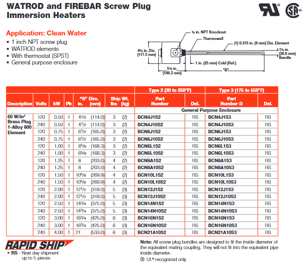
Specially designed for direct immersion heating of liquids, it can be used for heating various oils, heat transfer solutions, and other liquids. Typical applications include industrial rinse tanks, steam degreasing equipment, hydraulic oil heating, antifreeze (ethylene glycol) solution heating, and other scenarios. For example, in clean water heating scenarios, a 1-inch NPT screw plug paired with WATROD components can meet the heating needs of different water qualities such as deionized water and drinking water.
2. Structure and Component Characteristics
Heating element: It includes WATROD circular tubular element and FIREBAR flat tubular element, both of which adopt a hairpin bending design. According to the compatibility between the element sheath and the plug material, they are fixed on the spiral plug by welding or brazing. Among them, WATROD hair clips undergo recompacted treatment to maintain magnesium oxide (MgO) density, dielectric strength, heat transfer efficiency, and service life.
Terminal box: The standard configuration is a universal terminal box, and optional types such as moisture-proof, explosion-proof, and moisture-proof explosion-proof composite are provided to adapt to different environmental requirements. For example, in humid or explosive gas environments, corresponding protective terminal boxes can be selected, and the terminal boxes can be rotated for easy connection with existing conduits.
Auxiliary components: Some models are equipped with integral thermocouple sleeves, which facilitate the insertion and replacement of temperature sensors without the need to drain the heated fluid; Optional thermostats can achieve convenient process temperature regulation, such as SPST (single pole single throw) and DPST (double pole single throw) types, with a temperature control range covering 30-550 ° F.
3. Key performance parameters
Power and Voltage: The power density can reach up to 120 W/in ² (18.6 W/cm ²), with a power range from 250 watts to 38 kilowatts, voltage adaptation to 120-480VAC, and UL certification ® CSA component certification supports up to 480VAC and 600VAC respectively.
Sheath material and temperature: Different sheath materials correspond to different maximum operating temperatures. Alloy 800/840 sheath has a maximum temperature of 1600 ° F (870 ° C), 304/316 stainless steel sheath has a maximum temperature of 1200 ° F (650 ° C), and steel sheath has a maximum temperature of 750 ° F (400 ° C), which can be selected according to the temperature requirements of the heating medium.
Size specifications: Spiral plug sizes include NPT specifications such as 3/4 inch, 1 inch, 1.25 inch, 2 inch, 2.5 inch, and some also support European G-type (brass material) and BSP type (stainless steel material) thread standards. Taking a 1-inch NPT plug as an example, it can be paired with 0.260-inch and 0.315-inch WATROD components; The 2.5-inch NPT plug can be compatible with 0.430-inch, 0.475-inch WATROD components and 1-inch FIREBAR components.
4. Customization and accessory options
Material customization: In addition to standard sheath and plug materials, special sheath materials such as Hastelloy C276 and titanium alloy, as well as plug materials such as 304H, 316H, and 321 stainless steel, can also be provided to meet the needs of highly corrosive or special working conditions.
Functional accessories: optional indicator lights (PL10 and PL11 models), PL10 is compatible with up to 250VAC and equipped with 6-inch (152mm) leads; PL11 is compatible with 480VAC and equipped with 4-inch (102mm) leads, which can visually display the power on/off status of the heater. In addition, an adapter for spiral plugs to flanges is also provided, which facilitates the replacement of spiral plug heaters with flange heaters. The adapter material is mostly steel, and different specifications correspond to different shipping weights. For example, the shipping weight of the 1.25 inch to 3-inch to 150 # adapter is 13 pounds (5.9kg).
(2) ANSI Flange Immersion Heater (WATROD and FIREBAR ANSI Flange)
1. Product features and applicable scenarios
Suitable for scenarios that require high-power heating and high installation stability, such as liquid heating in large storage tanks and industrial reactors. It can handle various media such as clean water, process water, heavy oil, asphalt, etc. Its flange structure ensures sealing performance under high pressure conditions, with pressure ratings ranging from 150 pounds, 300 pounds, 600 pounds, etc.
2. Core parameters and structure
Power and density: The power density can reach up to 100 W/in ² (15.5 W/cm ²), providing higher heating power to meet the rapid heating needs of large capacity media.
Flanges and components: Flange sizes range from 2 inches to 48 inches, suitable for different equipment interfaces; The heating element also includes WATROD and FIREBAR types, and the connection method between the element and the flange is determined based on material compatibility to ensure pressure sealing effect.
Protection and Control: The terminal box type is similar to the screw plug type, supporting universal, moisture-proof, explosion-proof, etc. It can also be matched with thermocouples and thermostats to achieve precise temperature control and monitoring.
3. Customization and adaptation
Support customization of flange size, pressure rating, and component arrangement according to customer needs. We can also provide flanges and components made of special materials to cope with harsh working conditions such as corrosion or high temperatures. For example, when dealing with highly corrosive solutions, flanges and components made of Hastelloy material can be used.
Typical application scenarios and adaptation solutions
(1) Water heating
1. Heating of clean water
Product selection: Common 1-inch, 1.25-inch, 2-inch, 2.5-inch NPT spiral plug heaters, paired with WATROD or FIREBAR components. Taking a 1-inch NPT screw plug as an example, if Alloy 800 sheath components are used, the power density can reach 60 W/in ² (9.3 W/cm ²), and the power can range from 0.5kW to 4kW at 240VAC. It is suitable for small water tanks, laboratory water heating and other scenarios.
Configuration options: Universal terminal box or moisture-proof terminal box can be selected, paired with SPST thermostat (temperature range 30-250 ° F or 175-550 ° F), such as models BCN4J1S2 (Type 2 temperature range) and BCN4J1S3 (Type 3 temperature range), both of which support next day shipping (RS identification).
2. Heating of deionized water/desalinated water
Material adaptation: Due to the possible corrosiveness of deionized water, components with 316 stainless steel plugs and 316 stainless steel sheaths are usually selected, such as 2.5-inch NPT spiral plug heater, model BLR77L3S4, sheath material of 316 stainless steel, power 3kW, voltage 240VAC, power density 9.3 W/cm ², which can effectively resist the corrosion of deionized water and ensure long-term stable operation.
Control and Protection: K-type thermocouples can be equipped for precise monitoring of process temperature. The terminal box is selected as moisture-proof and explosion-proof, suitable for environments that may be humid or have slightly corrosive gases.
3. Heating of process water
Product type: Depending on the flow rate and heating requirements of the process water, a 1.25-inch NPT FIREBAR element heater or a 2-inch NPT WATROD element heater can be selected. For example, a 1.25-inch NPT FIREBAR heater, model BDNF13A27S5A, with a power of 2.0kW, a voltage of 240VAC, and a power density of 7 W/cm ², is suitable for heating medium flow process water; 2-inch NPT WATROD heater, model BGS79J6S4, power 1.0kW, voltage 120/240VAC, compatible with different process equipment interfaces.
Installation requirements: It is necessary to ensure that the heater is installed on the path of the process water flow, and that the components are completely immersed in the water to avoid dry burning. At the same time, the installation angle of the components should be adjusted according to the direction of the water flow to improve heat transfer efficiency.
(2) Heating of oils and viscous media
1. Heating of light oil and heat transfer oil
Power density control: Due to the relatively low heat transfer efficiency of oils, heaters with medium power density, such as 23 W/in ² (3.6 W/cm ²), are usually selected. Taking the 1-inch NPT WATROD heater as an example, model BCS6J1S, with steel sheath material, power of 0.25kW, voltage of 120VAC, suitable for heating lightweight lubricating oil; 1.25-inch NPT WATROD heater, model BES6G6S, power 0.5kW, voltage 120/240VAC, can be used for heating heat transfer oil.
Structural design: Some models use flat FIREBAR components, which can increase the contact area with oil and improve heating uniformity, such as the 1.25-inch NPT FIREBAR heater, model BDNF 16G12S5A, power 1.7kW, voltage 240VAC, suitable for small oil tank heating.
2. Intermediate oil heating
Low power density adaptation: Medium quality oil has poor fluidity and requires the use of a lower power density heater, such as 15 W/in ² (2.3 W/cm ²), to avoid local overheating and carbonization of the oil. For example, a 1.25-inch NPT FIREBAR heater, model BDNF 13A29S5A, with a power of 0.67kW and a voltage of 240VAC, is suitable for heating medium lubricating oil; 2-inch NPT WATROD heater, model BHN79N12S4, power 1.0kW, voltage 240VAC, suitable for heating medium quality oil storage tanks.
Temperature control: Equipped with DPST thermostat with a temperature control range of 60-250 ° F to prevent excessive oil temperature. At the same time, a low level sensor can be selected to avoid dry burning and damage to the heater due to low oil level.
3. Heating of heavy oil, asphalt, and # 6 fuel oil
Extremely low power density: This type of medium has extremely high viscosity and poor heat transfer efficiency, requiring the use of heaters with extremely low power density, such as 8 W/in ² (1.3 W/cm ²). For example, a 1.25-inch NPT FIREBAR heater, model BDNF 16G22S5A, with a power of 0.43kW and a voltage of 240VAC, is suitable for the initial stage of asphalt heating; 2.5-inch NPT WATROD heater, model BLS717E12S4, with a power of 1.0kW and a voltage of 240VAC, can be used for heating and insulation of # 6 fuel.
Structure and Installation: Heaters are usually designed with long components to increase the contact length with the medium and improve heating efficiency. At the same time, the flowability of the medium should be considered during installation to avoid the heater being covered by sediment and affecting heat transfer. In addition, explosion-proof terminal boxes can be selected to adapt to the combustible gas environment that may be generated during the heating process of heavy oil.
(3) Heating in other special scenarios
1. Forced air heating
Product type: Multiple choice 1.25-inch NPT WATROD element heater, sheath material is 304 stainless steel, power 1.0-2.0kW, voltage 120/240VAC, such as model BEN13G6S, power 1.0kW, voltage 120/240VAC, can be used with a fan to achieve forced air circulation heating, suitable for winter insulation in small workshops and equipment rooms.
Protection requirements: The terminal box should be dust-proof to prevent dust from entering and affecting electrical performance. At the same time, the installation position of the heater should be away from flammable materials to prevent fire risks.
2. Heating of corrosive solutions
Special material selection: The sheath material is made of Hastelloy C276 or titanium alloy, and the plug material is 316 stainless steel to resist corrosion from solutions. For example, a 2.5-inch NPT WATROD heater with a sheath material of Hastelloy C276, a power of 3.0kW, a voltage of 240VAC, suitable for heating acidic solutions; 1.25-inch NPT WATROD heater with titanium alloy sheath material, power of 0.7kW, voltage of 120VAC, suitable for heating alkaline solutions.
Sealing and Protection: The connection between components and plugs adopts a special welding process to ensure sealing performance and prevent solution from infiltrating and corroding electrical components. The terminal box adopts a fully sealed moisture-proof and explosion-proof type to further improve the protection level.
Ordering Information and Delivery
(1) Model coding rules
The model code contains multiple parameter information. Taking the screw plug heater as an example, such as “BCN4J1S2”:
BC “: represents the basic series (screw plug type, WATROD component);
N “: indicates the material of the plug (brass);
4 “: corresponds to size” B “(4.5 inches, 114mm);
J “: Component diameter (0.315 inches, 8mm);
1: Voltage (120VAC);
S “: Terminal box type (universal type);
2 “: Thermostat type (Type 2, temperature range 30-250 ° F).
The core configuration of the heater can be quickly identified through model coding, facilitating accurate ordering.
(2) Delivery cycle
Standard products: Products with the “RS” logo support next day shipping, such as most 1-inch and 1.25-inch NPT spiral plug heaters, meeting emergency needs. For example, models BCN4J1S2, BDNF 13A27S5A, etc. have sufficient inventory and can be arranged for shipment the next day after placing an order.
Customized products: Customized products that require special materials, sizes, or functions, with a delivery cycle determined by specific needs, usually 2-4 weeks. For example, the selection of Hastelloy C276 sheathed heaters, customized size flange heaters, etc. require material procurement, processing and manufacturing, testing and other processes, with a relatively long delivery cycle.
(3) Accessories ordering
Sealing accessories: Multiple materials of gaskets are available, such as rubber gaskets (suitable for water-based media), asbestos free gaskets (suitable for general industrial scenarios), and wound gaskets (suitable for high-pressure conditions), which can be selected according to the usage scenario and pressure level of the heater.
Installation accessories: including lifting lugs (for easy installation and disassembly of large heaters), baffles (to prevent direct impact of media on components, protect components), extended lead thermocouples (for remote temperature monitoring), etc., can be ordered separately according to actual installation needs.
Key points for installation and maintenance
(1) Installation requirements
Immersion depth: The unheated section of the heater needs to be completely immersed in the heated medium, ensuring at least 1 inch (25mm) of unheated section is inside the medium to prevent overheating and damage to the unheated section. For example, in clean water heating, the unheated section of a 1-inch NPT heater needs to be completely submerged below the water surface to avoid exposure to air.
Installation position: The heater should be installed in the lower area of the container, but higher than the sediment layer at the bottom of the container, to prevent sediment from covering the components and affecting heat transfer. At the same time, it facilitates natural convection of the medium and improves heating uniformity. For containers with stirring devices, the heater should be installed within the range of the stirring blades to further enhance heat transfer.
Flow direction and angle: When installing the FIREBAR element heater, the installation angle of the element needs to be determined based on the flow direction of the medium, usually at a certain angle (such as 45 °) to reduce pressure loss and improve heat transfer efficiency. For example, in process water heating, FIREBAR components should be installed in the direction of water flow to avoid direct impact of water flow on the components causing wear.
Electrical connection: The electrical connection must comply with the national electrical specifications, and the specifications of the power cord should be selected according to the power and voltage of the heater to ensure sufficient current carrying capacity, while also taking waterproof and dustproof measures. The installation of terminal boxes should avoid direct exposure to rainwater or corrosive liquids. If installed outdoors or in humid environments, additional protective measures should be taken.
(2) Maintenance points
Regular cleaning: Disassemble the heater regularly (e.g. every 3 months), clean the surface of the components of dirt, sediment, and other impurities to prevent affecting heat transfer efficiency. When cleaning, a soft bristled brush or specialized cleaning agent can be used to avoid scratching the protective cover of the component with sharp tools, which can lead to increased corrosion.
Status check: Check whether the protective sheath of the component is corroded, deformed, leaking, etc. If the sheath is found to be damaged, the component should be replaced in a timely manner to prevent the medium from infiltrating the interior and damaging the electrical components. At the same time, check the sealing performance of the terminal box to ensure that no moisture or dust enters, whether the electrical connections are tight, and whether there are any looseness or oxidation phenomena.
Calibration of temperature monitoring equipment: Regularly (e.g. every 6 months) calibrate temperature monitoring and control equipment such as thermostats and thermocouples to ensure the accuracy of temperature measurement and control. If the accuracy deviation of the equipment exceeds the allowable range, it should be adjusted or replaced in a timely manner.
Maintenance records: Establish a maintenance record file to record the maintenance time, content, problems discovered, and solutions taken for each maintenance, in order to track the usage status of the heater, predict possible failures in advance, and develop a reasonable maintenance plan.
Safety precautions
Prevent dry burning: Before running the heater, it is necessary to ensure that the medium has reached the specified liquid level and that the components are completely immersed in the medium. It is strictly prohibited to start the heater without medium or with insufficient medium liquid level to avoid dry burning causing component damage or even fire. Low level sensor can be installed to achieve low level protection. When the liquid level is lower than the set value, the heater power supply will be automatically cut off.
Explosion proof safety: In environments with explosive gases or dust, explosion-proof terminal boxes must be selected, and the installation of heaters must comply with explosion-proof regulations to avoid electrical sparks causing explosions. Regularly inspect the explosion-proof sealing surface. If damage or aging is found on the sealing surface, the sealing components should be replaced in a timely manner to maintain the explosion-proof performance.
Temperature control: It is strictly prohibited to operate beyond the maximum working temperature of the heater. Based on the characteristics and process requirements of the heated medium, the temperature control of the thermostat should be set reasonably to avoid overheating, decomposition or deterioration of the medium. For heat sensitive media, an over temperature protection device should be equipped to further improve safety.
Electrical safety: The grounding of the heater must be reliable to prevent leakage accidents. When conducting maintenance or overhaul, it is necessary to first cut off the power supply and hang a “Do Not Close” sign to avoid accidental power on and personal injury.
Core Display: Loop Name, Control Mode (Auto/Manual), Process Value (PV), Set Point (SP), Output Power (PWR)
Menu functions: configuration files (40, 50 steps per file), data logs, system settings (network/security)
Installation and wiring specifications
1. Installation method and size
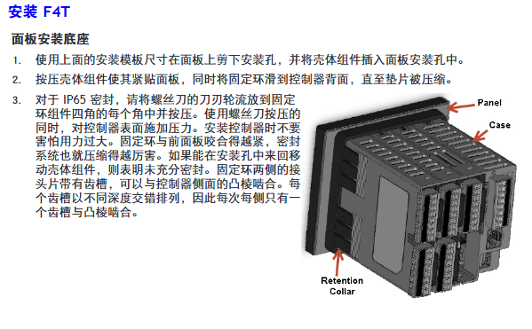
Key requirements for installation type
Panel installation hole size: 117.40mm (width) × 120.14mm (height); The fixing ring should be tightly attached to the panel to ensure an IP65 seal
Embedded installation requires PEM nut posts (such as S0-632-6 Z1 galvanized steel); The bracket is fixed with 6 # 6-32 screws, and the front panel needs to be covered
Install through the wall with a hole of 178 × 122mm; install the heat sink vertically, leaving a ventilation space of ≥ 102mm above and below
Torque: 2.7Nm (24 lb in), wire stripping length 11mm; re tighten after 48 hours, every 3-6 months
Power wiring: Terminals 98 (+) and 99 (-) should follow NEC or local electrical regulations to avoid parallel wiring with power lines
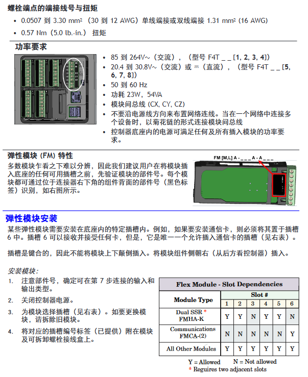
3. Installation of Elastic Module (FM)
Slot dependency rules:
The communication module (FMCA series) can only be installed in slot 6;
The high-density dual SSR module (FMHA-KAAA) requires 2 adjacent slots and cannot be placed in slots 3/6;
The module needs to be inserted with the component side facing right, and the key design prevents reverse installation.
Module identification: Confirm the part number through the black label in the lower right corner of the connector (e.g. FMMA-UKAA-AAA is 1 universal input+1 SSR output).
Input/output wiring and module specifications
1. Input wiring (some key types)
Input type wiring requires accuracy and range
Connect the negative electrode (red wire) of the thermocouple to the S terminal; The compensating wire should be made of the same alloy as the thermocouple; Input impedance>20M Ω J-type: ± 1.75 ℃ (0~750 ℃); K-type: ± 2.45 ℃ (-200~1250 ℃)
Digital input voltage input: ≤ 36V (3mA), ≥ 3V (0.25mA) activated; Dry contact: ≤ 100 Ω activated, ≥ 500 Ω inactive update rate 10Hz; maximum short-circuit current 13mA
Current transformer input 0~50mAac; Requires Watlow 16-0246 module; The load line needs to pass through the CT in the same direction with a response time of ≤ 1 second; Accuracy ± 1mA
2. Output wiring (some key types)
Output type wiring requirements specification parameters
Mechanical relay 240Vac/30VDC, 5A resistance load; Minimum 20mA load at 24V; When connecting Quencac (0804-0147-0000) 120/240Vac across coils, a guiding power of 125VA is required; Rated load 100000 cycles
Solid state relay (SSR) 24~264Vac, 0.5A at 149 ° F (65 ℃), 1A at 50 ° F (10 ℃); only AC load optically isolated; The maximum off state leakage current is 105 μ A; 20VA guidance power at 120/240Vac
Switching DC 22~32VDC open circuit voltage; 2 output combination current ≤ 40mA; when driving external SSR, connect to DC+/DC – short circuit limit<50mA; DIN-A-MITE compatible
Universal process output 0~10Vdc (minimum load of 1k Ω) or 0~20mA (maximum load of 800 Ω); Voltage/current output accuracy of ± 15mV (voltage)/± 30 μ A (current) cannot be used simultaneously; Temperature stability 100ppm/℃
Calibration and PC connection
1. Calibration operation
Calibration prerequisite: Accurate signal source is required (such as thermocouple 0.000~50.00mV, RTD 50.0~350.0 Ω). It is recommended to first verify whether the error exceeds the specifications (such as thermocouple ± 1.75 ℃).
Operation method:
Composer software: Connect device → Device menu → Calibration → Select module/input → Enter 2 limit values as prompted;
Front panel: Menu → Service → Calibration → Select module/input → Perform on-site calibration.
Notes:
The calibration values will be reset to factory settings and cleared;
3-wire RTD calibration requires cross connection of R, T, and S inputs;
The security settings are divided into “full access/read only/no access”, and without access permission, the calibration screen cannot be accessed.
2. PC connection and Composer software
Ethernet settings:
Default parameters: IP 192.168.0.222, subnet 255.255.255.0, gateway 0.0.0.0;
DHCP connection: F4T is connected to the switch, and the DHCP server automatically assigns an IP address;
Fixed IP connection: PC is directly connected to F4T, and the first three segments of PC IP are consistent with F4T (such as 192.168.0. XXX).
Composer software:
Function: Configure elastic module (check if slot module matches), customize function block (alarm/timer/mathematical operation);
Troubleshooting and Maintenance
1. Common faults and solutions (partial)
Possible causes and solutions for the fault phenomenon
Alarm cannot be cleared/reset. 1. Alarm latch activation; 2. Alarm source setting error 1. Reset when the process is within range; 2. Select the correct input instance
No serial communication 1. Address/baud rate mismatch; 2. EIA-485 wiring error 1. Unified device protocol parameters; 2. T+/R+connected to B, T -/R – connected to A
Temperature runaway (overshoot/undershoot): 1. Thermoelectric dipole polarity reversal; 2. Heater short circuit: 1. Connect the red wire to the S terminal; 2. Replace the heater/repair the wiring
No display 1. Power off; 2. The fuse is open circuit; 3. Voltage error: 1. Check the circuit breaker/interlock; 2. Replace the fuse; 3. Confirm 24/240Vac
The process cannot reach the set point 1. The controller is not tuned; 2. Set the control mode to “off”. 1. Perform automatic tuning; 2. Set as “PID” or “on-off”
2. Battery replacement
Battery specifications: Model BR2032 (Watlow part number 0830-0858-0000), nominal voltage 3V, lifespan of 10 years at 77 ° F (25 ℃), and replacement time of 7.5 years in harsh environments.
Replacement steps:
Turn off all power sources of F4T;
Use a small screwdriver to push out the battery holder from the side hole and remove the old battery (note the polarity clearly);
Insert the positive pole of the new battery to the left and reset the battery holder;
It is recommended to recycle used batteries and not dispose of them casually.
Model ordering rules (example: F4T11A1A1AA)
Example of optional values for field meanings
The first and second product series F4=T series controller
3rd basic type T=touch screen
4th application type 1=Standard, X=Custom
The 5th future option A=none, J=data record
6th power supply and connector 1=100~240Vac right angle connector (with identification)
The 7th and 8th bits of the configuration file and function block AA=no configuration file+basic function block
Customization options for positions 9-15 (connector/firmware/document) 1A=including DVD document+gray personalized border
Key issues
Question 1: What are the types of elastic modules (FM) for F4T controllers? What are the different types of core functions and slot installation rules?
Answer:
Types and core functions of elastic modules:
Hybrid I/O module (FMMA series): includes 1 universal input (supporting thermocouple/RTD/0~10V/0~20mA)+1 output (such as SSR, mechanical relay, switched DC), used for conventional temperature acquisition and load control, such as FMMA-UKAA-AAA (1 universal input+1 SSR output);
Restriction module (FMLA series): used for safety interlock control, including 1 input (universal/thermistor)+1-2 outputs (such as C-shaped relay, supporting normally closed interlock), such as FMLA-LCJ-AAA (restriction control with universal input+switched DC output);
High density I/O module (FMHA series): integrates multiple inputs/outputs, such as FMHA-RAAA-AAA (4 universal inputs), FMHA-JAAA-AAA (4 mechanical relay outputs), suitable for multi-channel acquisition and control scenarios;
Communication module (FMCA series): Only supports Modbus RTU protocol (EIA-232/485), used for serial communication between the controller and PLC/PC, such as FMCA-2AA-AAA.
Slot installation rules:
Exclusive slot: The communication module (FMCA series) can only be installed in slot 6 and cannot be recognized in other slots;
Multi slot requirement: Some high-density modules (such as dual SSR output FMHA-KAAA) require 2 adjacent slots and cannot be placed in slot 3 (single slot design);
Keying error prevention: The module has a keying structure and cannot be inserted upside down. The component side should face right (when viewed from the back of the controller);
Label requirement: After installation, slot number labels should be affixed to the module and junction box to avoid controller failure caused by inserting the wrong slot during replacement.
Question 2: How to correctly wire the thermocouple input of F4T controller? What steps should be followed when calibrating thermocouple inputs?
Answer:
Requirements for correct wiring of thermocouples:
Polarity differentiation: The negative lead of a thermocouple is usually red and must be connected to the S terminal (signal negative) of the module, while the positive lead is connected to the R terminal (signal positive). Reversing the connections can result in incorrect temperature readings;
Compensation wire: It is necessary to use a compensation wire made of the same alloy as the thermocouple (such as K-type compensation wire for K-type) to reduce the influence of ambient temperature on readings;
Insulation requirements: The input impedance of the thermocouple should be greater than 20M Ω, and the maximum source resistance should be 2k Ω. When wiring, it is necessary to avoid parallel wiring with the power line to prevent electromagnetic interference;
Open circuit detection: The module has a built-in 3 μ A open circuit sensor for detection. If the wiring is open, it will trigger an “incorrect input” alarm.
Thermocouple input calibration steps (using Composer software as an example):
Preparation equipment: high-precision millivolt signal source (if able to output 0.000~50.000mV), copper wire (to minimize wiring error), voltage/ohmmeter (to verify the accuracy of the signal source);
Software connection: Start Composer → Connect F4T (enter IP 192.168.0.222) → Enter “Device menu → Calibration”;
Select channel: Select the module where the thermocouple is located and the input channel (such as input 1 of slot 1) in the “pluggable module”;
Enter calibration value:
Input the lower limit signal (such as 0.000mV, corresponding to 0 ℃) to the module, enter the actual signal value in the software, and click “Calibrate Lower Limit”;
Input the upper limit signal (such as 50.000mV, corresponding to approximately 1200 ℃, depending on the thermocouple type), input the actual value, and click “Calibrate Upper Limit”;
Verification and saving: After calibration, input the intermediate value (such as 25.000mV) to the module, confirm that the displayed value and actual value error are ≤ specifications (such as J-type ± 1.75 ℃), and save the calibration data;
Attention: If the factory settings are restored after calibration, the calibration values will be cleared; The calibration of a 3-wire RTD requires crossing the R, T, and S terminals, and the lead resistance should be ≤ 10 Ω.
Question 3: What are the possible reasons for the F4T controller experiencing a “temperature runaway (continuous increase after process value overshoot)” fault? What are the corresponding troubleshooting and resolution steps?
Answer:
Possible reasons:
Output function setting error (such as heating output set to cooling);
Reverse wiring of thermocouple/RTD (e.g. thermocouple red wire connected to positive electrode, RTD S1 not connected to R1);
Controller output wiring error (such as SSR output L1/L2 reversed);
Heater or wiring short circuit (causing continuous power supply to the load);
Power controller connection defects (such as DIN-A-MITE and F4T signal interruption, unable to turn off the load);
The control algorithm is set to “on-off” and the hysteresis is too large (causing the heating to not stop in time).
Troubleshooting and resolution steps:
Check the output function settings:
Front panel: Menu → Settings → Output → Select the corresponding output channel, confirm that the “Function Type” is “Heating” (not “Cooling”);
If there is an error, modify it to the correct type and restart the controller to take effect;
Verify sensor wiring:
Thermocouple: Disconnect the wiring, confirm that the red wire (negative electrode) is connected to the S terminal, the positive electrode is connected to the R terminal, and if the wiring is reversed, reconnect it;
RTD: 3 wire type needs to confirm S1 (white wire) connected to R1, T1 connected to S2, lead resistance ≤ 10 Ω (measured with an ohmmeter);
Check the output wiring and load:
After the power is cut off, use a multimeter to check the on/off switch of the heater wiring. If there is a short circuit, replace the heater;
Check SSR/relay output: output 100% power to the controller, measure the output terminal voltage (such as 240Vac), and the voltage should disappear after power failure. If there is continuous voltage, replace the SSR/relay;
Verify power controller connection:
If using a DIN-A-MITE power controller, check the signal lines between F4T and DIN-A-MITE (such as switched DC output) to ensure that there is no looseness/disconnection and that the signal can trigger DIN-A-MITE shutdown normally;
Adjust control algorithm:
If it is “on-off” control: menu → control → algorithm → change to “PID”, execute automatic tuning (TRU-TUNE) ®+), Reduce overshoot;
If PID overshoot occurs: adjust the proportional band (increase) or integral time (extend) to reduce response speed;
Test validation:
Power on again, set the target temperature (such as 100 ℃), observe whether the process value stabilizes within the set point ± accuracy range (such as ± 1 ℃), and if it still loses control, troubleshoot the controller output hardware (such as replacing the output module).
Product basic information and manufacturer background
1. Product positioning and manual usage
This product is an industrial grade solid-state power controller, with the model identification as “DIN-A-MITE ® Style C”, The manual clearly states that its core function is to guide users in completing product installation, wiring, parameter configuration, and safe operation and maintenance. It also includes specifications and recommended solutions for semiconductor fuses that users are concerned about, and emphasizes the need to follow national and local electrical safety regulations during installation.
2. Core configuration range of the product
Electrical basic parameters: Supports single-phase, three-phase 2-leg, and three-phase 3-leg (suitable for four wire star loads) configurations, with AC voltage coverage of 120-600V (ac) and current switching capability ranging from 30-80A depending on the model. Please refer to the output rated curve for specific specifications 🔶 1-9.
Control and protection options: Provide zero crossing variable time base or AC/DC input contactor versions, some zero crossing models have thyristor (SCR) short circuit protection and heater open circuit protection; Single phase models additionally support phase angle control and phase angle control with current limitation, and product configuration information can be directly identified through model coding.
Detailed technical specifications
1. General electrical parameters
(1) Current is related to power
Rated current: Please refer to the output rated curve on page 5. Different cooling methods (natural convection, fan cooling, through wall installation) and load types (resistive heater load) correspond to different rated values, and it is clear that the rated value is based on the resistive heater load 🔶 1-22.
Transient and limit current: The maximum peak surge current within 16.6 milliseconds is 1350A; the selection of fuses must meet the maximum value of 9100 A ² s for I ² t; The minimum latch current of SCR is 500mA, and the minimum holding current is 200mA to ensure stable triggering and operation of the device 🔶 1-24 🔶 1-25 🔶 1-26.
Auxiliary current and power consumption: The fan current varies depending on the power supply -0.14A at 24V (dc), 0.12A at 120V (ac), 0.06A at 240V (ac); the maximum off state leakage current is 1mA at 25 ° C (77 ° F); the power loss of each controlled branch is 1.2 watts/ampere (calculated based on switching ammeter) 🔶 1-28 🔶 1-29.
(2) Voltage range
Segmented by voltage level input range: 24-48V (ac) models with minimum 20V and maximum 53V; 120-240V (ac) models with minimum 48V and maximum 265V; 277-600V (ac) models with minimum 85V and maximum 660V, covering commonly used industrial voltage scenarios and adapting to different regional power grids 🔶 1-33 🔶 1-34.
(3) Environmental adaptability
The working humidity is 0-90% relative humidity (without condensation), and the storage temperature range is -40 to+85 ° C (-40 to 185 ° F); The insulation performance has only been tested below an altitude of 3000 meters, and additional evaluation is required for high-altitude scenarios 🔶 1-74 🔶 1-75; Simultaneously passing IEC 60068-2-32 (impact) and IEC 60068-2-6 (vibration) tests to ensure the anti-interference ability of industrial environments 🔶 1-59.
2. Operator interface and alarm function
(1) Interface configuration
Standard configuration includes command signal input and indicator lights, alarm output and indicator lights, and current limit indicator LEDs. Users can intuitively monitor the operating status of the equipment and quickly identify key working conditions such as signal input, alarm triggering, and current limit 🔶 1-18 🔶 1-19.
(2) Alarm function (limited to zero crossing models only)
SCR short circuit alarm: When the input command signal is turned off, but the current transformer detects a load current of 10A or above, an alarm is triggered (2 turns of winding are required for 5A current, 3 turns of winding are required for 2.5A current), and the alarm state is an abnormal combination of “signal off+load current present”.
Heater open circuit alarm: Only applicable to models with input control signal option “S”. It is triggered when the input command signal is turned on, but the load current detected by the current transformer is lower than the alarm set value, covering the fault scenario of “signal on+insufficient current”.
Alarm output characteristics: The alarm output is non latch type and is powered on when triggered; Adopting bidirectional thyristor (Triac) output, compatible with external power supply of 24-240V (ac), rated current varies at different temperatures -300mA at 25 ° C (77 ° F), 200mA at 50 ° C (122 ° F), 100mA at 80 ° C (176 ° F), typical holding current of 200 μ A, latch current of 5mA 🔶 1-42.
3. Certification and Security Compliance
International certification: meets ROHS environmental requirements; CE certification requires the use of appropriate filters to cover the 2004/108/EC Electromagnetic Compatibility Directive (EN 61326 Industrial Immunity Class A emission, not applicable to Class B environment) and the 2006/95/EC Low Voltage Directive (EN 50178 safety requirements), but phase angle and phase angle input control signal types with current limitation (P and L) do not have CE certification 🔶 1-45 🔶 1-46 🔶 1-47 🔶 1-48 🔶 1-49 🔶 1-50 🔶 1-51.
North American certification: UL ® 50 Type 4X shell certification, UL ANSI/ISA 12.12.01 temperature code T4A; The through wall heat sink component is suitable for Class I, Zone 2, Groups A, B, C, and D hazardous and non hazardous areas, but safety warnings such as “replacing any component may affect the applicability of hazardous areas” and “cannot be disconnected when the circuit is live unless the area confirms that there is no flammable concentration” are clearly stated 🔶 1-54 🔶 1-55 🔶 1-56; Simultaneously for UL ® 508 listed products, C-UL ® Document number E73741.
Installation specifications and size requirements
1. Installation method and steps
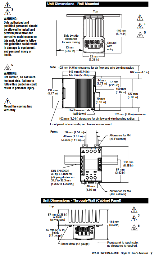
(1) DIN rail installation (DIN EN 50022, 35 × 7.5mm rail)
Installation steps: ① Push the device in and press down to clamp the top rail hook into the rail; ② Rotate the bottom of the device towards the guide rail; ③ The guide rail buckle will “click” to fasten. If it is not fastened, check whether the guide rail is bent; ④ The heat sink must be installed vertically (core requirement to ensure heat dissipation efficiency) 🔶 1-223 🔶 1-224 🔶 1-225.
Disassembly steps: Press and release the buckle, while rotating the device upwards and away from the guide rail to remove it.
Spacing requirement: A 102mm (4.0 inches) gap should be reserved on the side for airflow and wire bending radius; The front is designed with anti touch features, requiring no additional clearance; Minimum snap distance 34.8mm (1.37 inches), maximum 35.3mm (1.39 inches) 🔶 1-236 🔶 1-245.
(2) Panel installation
Four M4 (# 8) fasteners are required for fixation. Please refer to the panel installation dimension diagram on page 7 of the manual for specific dimensions, with a focus on the grounding wire entry position (13mm/0.50 inches) and the parallel arrangement wire gap (83mm/3.25 inches).
(3) Wall through installation (UL) ® 50 Type 4X Shell Model
Installation steps: ① Drill holes and cut the panel according to the size diagram on the right; ② Remove the mounting screws from the heat sink; ③ Tear off the protective film of the silicone gasket, attach the gasket to the heat sink, and ensure that the gasket hole is aligned with the heat sink screw hole; ④ Vertically install heat sink, torque controlled at 2.26-2.82 Nm (20-25 inch pounds) 🔶 1-257 🔶 1-258 🔶 1-259.
Size and Gap: The panel opening should meet the contour requirements of 178mm (7.00 inches) × 122mm (4.81 inches), and a minimum gap of 102mm (4.0 inches) should be reserved above and below the heat sink for airflow. A minimum gap of 10mm (0.4 inches) should be reserved on both sides.
2. Requirements for wiring terminals
(1) Input terminal (control signal type)
Adopting a crimping design, compatible with 0.2-1.5mm ² (24-16 AWG) wires; Use a 3.5mm (1/8 inch) flathead screwdriver and tighten to a torque of 0.5 Nm (4.4 inch pounds); The stripping length of the wire is 5.5mm (0.22 inches); The insulation level of the wire must be ≥ 75 ° C and is only applicable to copper conductors 🔶 1-61 🔶 1-62 🔶 1-63 🔶 1-64.
(2) Main circuit terminals (phase line, load, grounding)
Also of crimping type, compatible with 2.5-25mm ² (14-3 AWG) wires; Can be tightened with a 6.4mm (1/4 inch) flathead screwdriver or a 1A type # 2 Pozidriv screwdriver to a torque of 2.7 Nm (24 inch pounds); Wire stripping length 11mm (7/16 inches); Core maintenance requirement: Re tighten after 48 hours (to reduce wire cold flow), and then re tighten every 3-6 months thereafter 🔶 1-66 🔶 1-67 🔶 1-68 🔶 1-69 🔶 1-70.
(3) Cooling fan terminal
Adopting a quick connect design (1/8 inch push in), compatible with 16-14 AWG wires; Recommend using Amp part number 640929-1 or equivalent product 🔶 1-85.
Control mode and signal configuration
1. Zero crossing control mode (including contactor and proportional control)
(1) Type of contactor (input control signal)
DC input (Type C): 4.5-32V (DC) input, with a maximum current of 6mA per channel at 4.5V. An additional 2mA total current is required for each additional LED; To extend the service life, the cycle time should be less than 3 seconds 🔶 1-94.
AC input (Type K): Suitable for 24V (ac) ± 10%, 120V (ac)+10%/-25%, 240V (ac)+10%/-25%, with a maximum current of 25mA per circuit; it is strictly prohibited to share with temperature controllers with RC buffer circuits. If used, the RC buffer circuit must be removed first; Cycle time should be less than 3 seconds to extend lifespan 🔶 1-95 🔶 1-98.
(2) Proportional control (Type F, 4-20mA DC)
Variable time base control for loop power supply, only applicable to F0 input option; A current source of 8.0V (dc) or higher is required, with no more than 2 series inputs; Linearity requirements: Full open point 19.5-19.9mA (dc), maximum peak voltage 6.2V; Input output power accuracy ± 5% (0% -100% range, 4.3-19.7mA or 12.3-19.7mA); Temperature stability<0.15%/° C 🔶 1-96 🔶 1-102 🔶 1-105 🔶 1-106.
2. Phase angle and single cycle variable time base control
(1) Phase angle control (single-phase specific)
Applicable models: Type P (pure phase angle), Type L (phase angle with current limitation), only supports single-phase configuration, and has no alarm option 🔶 1-111.
Input signal: Supports 0-20mA, 4-20mA, 12-20mA (DC) and 0-5V, 1-5V, 0-10V (DC); Input impedance: 4-20mA signal is 250 Ω, linear voltage signal is 5k Ω 🔶 1-112.
Output and accuracy: Output voltage covers 100-120V, 200-208V, 230-240V, 277V, 400V, 480V, 600V (ac), deviation -15%/+10%, frequency 50/60Hz (deviation ± 5%); At 25 ° C, the output conduction time is directly proportional to the command signal, with an accuracy of ± 5%; Temperature stability<0.25%/° C 🔶 1-115 🔶 1-117.
Soft start function: 5-second soft start when powered on, soft start when thermostat overtemperature occurs, soft start when half cycle dropout detection occurs, 1-second soft switching when set value changes, protecting load and devices 🔶 1-124 🔶 1-125 🔶 1-126.
(2) Single cycle variable time base (Type S)
Working logic: At 50% power, “1 cycle on, 1 cycle off”; At 25% power, “conduct for 1 cycle and close for 3 cycles”; Continuous conduction for no more than 1 cycle when power is less than 50%, and continuous shutdown for no more than 1 cycle when power is greater than 50% 🔶 1-110.
Accuracy and adaptability: The output power is proportional to the command signal at 25 ° C, with an accuracy of ± 5%; Temperature stability<0.25%/° C; supports linear voltage, 4-20mA or potentiometer input 🔶 1-120.
3. Resolution and Additional Options
Resolution: The accuracy of the output variation relative to the input range is greater than 0.1%.
Manual control kit: Optional 1k Ω single turn potentiometer (with 0-100% dial), part number 08-5362.
Ordering coding rules and current levels
1. Model code disassembly (complete code: DC+phase+cooling/current+voltage+control signal+alarm+language+customization)
Meaning and Options of Encoding Segments
DC prefix: Fixed identifier (DIN-A-MITE Style C)
Phase configuration 1=single-phase 1 controlled leg; 2=Three phase 2 controlled legs; 3=Three phase, three controlled legs (four wire star); 8=2 independent area; 9=3 independent areas
Cooling/current 0=natural convection (standard DIN rail/panel heat sink); 1=120V AC fan cooling; 2=240V AC fan cooling; 3=24V DC fan cooling; T=Natural convection (wall/cabinet type heat sink, UL 50)
Voltage level 02=24-48V AC (C/F/K control); 12=100-120V AC (L/P/S control); 20=200-208V AC (L/P/S control); 24=120-240V AC(C/F/K)/230-240V AC(L/P/S); 27=277V AC(L/P/S); 40=400V AC(L/P/S); 48=480V AC(L/P/S); 60=277-600V AC(C/F/K)/600V AC(L/P/S)
Control signal C0=4.5-32V DC contactor; K1=22-26V AC contactor; K2=100-120V AC contactor; K3=200-240V AC contactor; F0=4-20mA ratio (loop power supply); L (0-5)=phase angle with current limitation (single-phase); P (0-5)=phase angle (single-phase); S (0-5)=single cycle variable time base; Input types corresponding to 0-5 in parentheses: 0=4-20mA, 1=12-20mA (S only), 2=0-20mA, 3=0-5V DC, 4=1-5V DC, 5=0-10V DC
Alarm option 0=No alarm; S=SCR short circuit alarm (not applicable to 8/9 area or L/P control); H=heater open circuit+SCR short circuit alarm (only S control)
Manual language 0=English; 1=German; 2=Spanish; 3=French
Mandatory scenario: When the load current is greater than 6A and the frequency is 150-250kHz, an external EMI filter must be used. Watlow verified that the “Tank Filter” can effectively suppress the EMI generated by the SCR power controller and meet the conducted emission limit.
Filter selection: For single-phase 230V (ac), choose Crydom 1F25 or Watlow 14-0019; Choose Crydom 3F20 or Watlow 14-0020 for three-phase 440V (ac); At the same time, a warning is issued that “slot filters may suppress useful communication in the 150-250kHz frequency band (such as baby monitors, medical alarm systems), and there is no safety risk that needs to be verified in advance” 🔶 1-437.
Core positioning of product series: Maximum operating temperature, maximum power density, key advantages
FIREROD ® Universal plug-in heater 1400 ° F (760 ° C) (Alloy 800 sheath) 400 W/in ² (62 W/cm ²) 60 years of industry validation, high thermal conductivity efficiency, supports multi scenario customization
High temperature FIREROD high-temperature working condition specific 1800 ° F (982 ° C) 100 W/in ² (15.5 W/cm ²) sealing design reduces oxidation, high emissivity sheath enhances heat transfer
Metric FIREROD global adaptation 1400 ° F (760 ° C) 330 W/in ² (50 W/cm ²) meets metric standards, has high dimensional accuracy, and is compatible with international equipment
MULTICELL ™ Multi zone precise temperature control 2050 ° F (1120 ° C) 30 W/in ² (4.6 W/cm ²) up to 6 independent temperature control zones, loose assembly design for easy disassembly and assembly
2. Core common advantages
Material and Structure: Made of nickel chromium resistance wire (uniform heating), magnesium oxide (MgO) insulation layer with specific grain purity (high dielectric strength, rapid heating), Alloy 800 or stainless steel sheath (anti-oxidation, corrosion-resistant).
Process design: Minimize the distance between the resistance wire and the sheath, reduce internal temperature, and support high power density operation; UL ®/ CSA certified leads, with insulation levels ranging from 250 ° C to 842 ° C.
Safety and reliability: non-volatile design, strong high-temperature stability; Some models support low leakage construction and are suitable for sensitive scenarios such as healthcare.
Detailed explanation of key technical specifications
1. Dimensions and tolerances
(1)FIREROD ® standard size
Nominal diameter (in) Actual diameter (in/mm) Minimum sheath length (in/mm) Maximum sheath length (in/mm) Diameter tolerance
Length tolerance: The sheath with a length tolerance of ≤ 4.5 in (114 mm) is ± 3/32 in (± 2.4 mm); The sheath with a diameter greater than 4.5 inches is ± 2% (1/8 inch diameter is ± 3%).
Power tolerance: 1/8 inch diameter is+10%/-15%, other diameters are+5%/-10%.
Resistance tolerance: 1/8 inch diameter is+15%/-10%, other diameters are+10%/-5%; Resistance varies with temperature, with room temperature (before use) being 90% of the value calculated by Ohm’s Law, and after use being 95%.
2. Electrical performance
(1)FIREROD ® Voltage and power range
Diameter (in) Maximum voltage (V) Maximum current (A) 120V Minimum power (W) 240V Maximum power (W)
Diameter (mm) Maximum voltage (V) 230V Maximum power (W) 400V Maximum power (W) Maximum current (A)
6.5 250 1650 – 7.2
16 480 4830 8400 21
20 480 4830 8400 21
3. Power density and application adaptation
Power density directly affects heating efficiency and heater lifespan, and should be selected based on the heating medium and operating conditions
Metal heating: The maximum allowable power density varies with the aperture fit gap and temperature (for example, at 1400 ° F, a fit gap of 0.005 in corresponds to a power density of approximately 80 W/in ²).
Air/gas heating: At an ambient temperature of 70 ° F, the maximum allowable power density for a single heater is approximately 60 W/in ²; When multiple devices are parallel, they need to be multiplied by a correction factor of 0.95, and when equipped with a reflector, they need to be multiplied by 0.85.
Mobile air heating: The higher the wind speed, the greater the allowed power density (for example, at a wind speed of 100 FPM, the power density can reach 1000 W/in ²).
Installation and Wiring Guide
1. Installation preparation
Aperture matching: It is recommended that the aperture be 0.001-0.006 inches larger than the actual diameter of the heater (for metal heating). A gap that is too large can reduce thermal efficiency, while a gap that is too small may make disassembly difficult.
Installation location: The sensor should be installed in a temperature uniform area, away from the edge of the heat source; The sheath should be in full contact with the heating medium to avoid local overheating.
Environmental requirements: Avoid installing in close proximity to noise sources such as motors and relays; In humid environments, models with sealing (PTFE/silicone) should be selected.
2. Wiring specifications
(1) Lead type and specifications
Lead type, maximum temperature, applicable scenarios, wire diameter specifications (example)
GGS fiberglass 482 ° F (250 ° C) universal scenario 18 AWG (1/2 inch diameter heater)
MGT 842 ° F (450 ° C) high temperature scenario 18 AWG (3/4 inch diameter heater)
PTFE 392 ° F (200 ° C) corrosion-resistant scenario 20 AWG (3/8 in diameter heater)
Mineral Insulation (MI) 1500 ° F (815 ° C) Extreme High Temperature/Vibration Scenarios Conductor Diameter 0.044 in (3/8 in diameter heater)
(2) Wiring precautions
Lead length: Standard length of 12 inches (305 mm), customizable extension, extra long leads need to consider voltage drop (recommended wire diameter not less than 22 AWG).
Grounding requirements: Models with grounding leads must be reliably grounded to avoid the risk of electrical leakage; In high temperature scenarios, the lead wire should be kept away from the sheath (with a minimum length of 1 inch without thermal zone).
Multi zone control: MULTICELL ™ The heater needs to be wired separately for each temperature control zone to ensure independent adjustment.
3. Fixed method
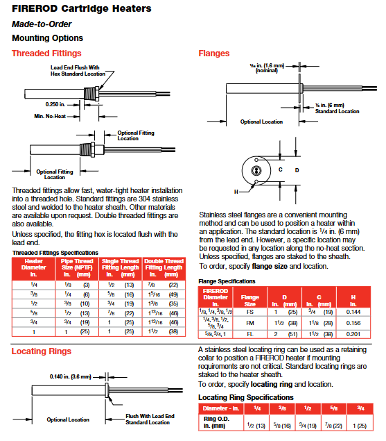
Flange fixing: Stainless steel flange (FS/FM/FL type), suitable for panel installation, flange position can be customized (standard distance from lead end 1/4 in).
Threaded fixation: 304 stainless steel or brass threaded joints (NPT/DIN specifications), waterproof installation, suitable for pipeline or threaded hole scenarios.
Positioning ring: Stainless steel positioning ring, used for non precision fixed scenarios, installed at the end of the no heat zone.
Customized Options and Selection Guide
1. Core customization options
(1) End and sealing options
Option Type Function Applicable Temperature Minimum No Hot Zone Length
PTFE seal and lead anti moisture, oil, solvent 392 ° F (200 ° C) 1 in (25 mm)
Silicone sealing and lead anti moisture, mild corrosion 302 ° F (150 ° C) 1 in (25 mm)
Epoxy resin sealing high temperature sealing (up to 260 ° C) 260 ° F (500 ° C) 1 in (25 mm)
Mineral Insulated (MI) Seal for Extreme High Temperature, Vibration, Corrosion 1500 ° F (815 ° C) 6 in (152 mm)
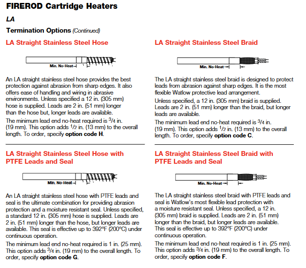
(2) Lead protection options
Stainless steel hose: wear-resistant, suitable for harsh environments, standard length of 12 inches, lead wire 2 inches longer than hose.
Stainless steel woven mesh: high flexibility, wear-resistant, standard length of 12 inches, supports right angle wire output.
Galvanized conduit: Abrasion protection, with 90 ° bend, standard length 8 inches.
(3) Function extension options
Built in thermocouples: Style A (monitoring the internal temperature of the heater), Style B (approximate workpiece temperature), Style C (end temperature, suitable for plastic molding), supporting J/K type.
Distributed power: Set different power densities in segments along the length of the heater to compensate for edge heat loss (suitable for scenarios such as sealing strips).
Dual voltage design: supports switching between two voltages and is suitable for multi scenario power supply (only available for metric models with diameters of 12.5 mm and above).
Extension without hot zone: The lead end or terminal without hot zone can be extended (up to 2.5 inches) to avoid the influence of high temperature on the lead.
2. Selection steps
Determine operating parameters: maximum working temperature, heating medium (metal/air/liquid), aperture and installation method.
Calculate power demand: Determine the required power based on the heating area, heating rate, and heat loss (recommended power density not exceeding the maximum allowable value of the corresponding medium).
Select product series: FIREROD for general scenarios ®, Choose high-temperature FIREROD for high temperature scenarios, metric models for international equipment, and MULTICELL for multi zone temperature control ™。
Customized function options: Select the sealing type according to the environment, choose the lead protection and fixing method according to the installation space, and select the built-in thermocouple according to the temperature control accuracy.
Maintenance and troubleshooting
1. Daily maintenance
Regular inspection: Check the insulation layer of the lead wires and the sheath for oxidation and discoloration every month, and replace them promptly if any problems are found.
Cleaning and maintenance: Remove dust and oil stains from the surface of the sheath to avoid affecting heat transfer; WATLUBE can be used for disassembly ™ Lubricant, easy to disassemble and does not affect thermal conductivity.
Life management: Under high temperature conditions (such as above 1400 ° F), it is recommended to regularly check the resistance value and replace the heater when the resistance changes by more than 10%.
2. Common faults and solutions
Possible causes and solutions for the fault phenomenon
Slow heating, insufficient power density, loose aperture fit, excessive lead voltage drop, replacement with higher power model, adjustment of aperture gap, and thickening of lead wire diameter
Improper installation position due to local overheating, poor medium contact, adjust installation position, and ensure that the protective cover is fully attached to the heating surface
Damaged leads, high temperature baking, wear, corrosion, extended no heat zone, replacement of protected lead options (hose/braided mesh), selection of corrosion-resistant seals
Excessive leakage, insulation layer affected by moisture or damage, replacement of sealing model, drying environment, and inspection of reliable grounding
High power density due to heater burnout, reduced power density due to dry burning of medium, ensuring sufficient heating medium, and installing temperature protection devices
Typical application scenarios
Semiconductor manufacturing: wafer bonding, chamber heating (using high cleanliness, low leakage FIREROD) ®, With PTFE seal).
Plastic molding: mold heating, sealing strip heating (using models with distributed power and built-in thermocouples).
Control mode: Supports PID or ON/OFF control, can be manually selected; Dual output design, output 1 can be set as heating or cooling, and output 2 can be set as heating, cooling, or off.
Input type: compatible with J, K, T, N, R, S, B, C, Pt2 thermocouples, RTD (2-wire or 3-wire) and 0-5VDC, 4-20mA process inputs.
Programming ability: Supports 24 step program curves, including four step types: set point (StPt), constant temperature (SoAh), jump cycle (JL), and end, and can achieve multi-stage temperature control.
Auxiliary functions: optional dual auxiliary output (alarm or time triggered event), set point/process value retransmission output, supports RS-422A/RS-423A/EIA-485 communication interface.
Data storage: Non volatile memory automatically saves all parameters, and data is not lost after power failure; Lithium battery backup operation parameters, with a service life of about 10 years.
Working environment: Temperature range of 32 ° F~149 ° F (0 ° C~65 ° C), humidity range of 0~90% (no condensation).
Installation and wiring process
Installation preparation
Panel Hole: Process panel holes according to size requirements (nominal 3.625 × 3.625 inches/92.08 × 92.08mm, thickness 0.06~0.25 inches/1.5~6.35mm).
Equipment fixation: Insert the controller housing into the opening, fix it from the back of the panel with the matching bracket, then insert the control chassis into the housing and lock it by rotating the front plate screw 90 ° clockwise (note that the screw should only be rotated 90 ° to avoid excessive force damage).
Wiring operation
Power wiring
Supports 120VAC or 240VAC power supply (50/60Hz universal, no adjustment required), requires connection to L1 and L2 power terminals and grounding terminals, and wiring must comply with the National Electrical Code (NEC) to avoid the risk of electric shock.
The power supply end needs to be connected in series with a fuse. When powered by 120VAC, the L1 end needs to be connected in series with a fuse. When powered by 240VAC, both the L1 and L2 ends need to be connected in series with a fuse.
Sensor wiring
Thermocouple: Use extension cords made of the same material as the thermocouple to avoid errors; If connecting non isolated external devices, an isolated thermocouple should be selected, with positive and negative terminals corresponding to terminals 7 (+) and 9 (-).
RTD: 2-wire RTD needs to short-circuit terminals 5 and 6, and 3-wire RTD needs to ensure that the resistance of the three extension wires is consistent (with the same wire diameter and material) to compensate for lead resistance errors (every 1 Ω lead resistance of 2-wire RTD will cause an error of about+2 ° C).
Process input: 0-5VDC input is connected to terminals 1 (+) and 3 (-), with an input impedance of 100K Ω; 4-20mA input requires short circuiting terminals 2 and 3, followed by connecting the positive and negative poles of the signal, with an input impedance of 249 Ω.
Output wiring
Output 1/2: Select the wiring method according to the model (solid-state relay, mechanical relay, DC switch, process output, etc.), refer to the wiring diagram of the corresponding model in the manual for details, and ensure that the load impedance matches (such as process output 4-20mA maximum load 600 Ω).
Auxiliary output: 6 auxiliary options are available (single relay, dual relay, relay+retransmission, etc.), wired according to the corresponding terminals (24-27) of the model, and the alarm/event output is a mechanical relay( 6A@28VDC /120VAC)。
Wiring precautions
Separation of strong and weak electricity: The sensor signal line (low power) is wired separately from the power line and output line (high power), with a minimum spacing of 12 inches (305mm) to avoid cross interference; When crossing, use a 90 ° crossing.
Shielding and grounding: Shielded cables are used for low-level signal lines, and the shielding layer is only grounded at the controller end; The system is grounded at a single point to avoid grounding loops, and all grounding terminals are connected to a unified grounding body.
Parameter Configuration Guide
Enter the configuration menu
Press the UP and DOWN keys simultaneously for 3 seconds to enter the Setup menu (displaying LOC parameters); Continue holding down the UP and DOWN keys under the LOC parameter to enter the calibration menu.
During the configuration process, press the MODE key to switch parameters, use the UP/DOWN key to adjust values, and if there is no operation for 5 seconds, it will automatically save and return to the previous level, or press the MODE key to manually save and switch.
Key configuration parameters (Setup menu)
Parameter Category Core Parameter Function Description Default Values
Security and Permission LOC Operation Permission Lock (Level 0-3): Level 0 Full Permission, Level 3 Only View Setpoint/Process Values 0
Input configuration In Select input type (such as J, K, RTD, 4-20, etc.) J or r
Temperature unit (° F/° C), only displays F when input as thermocouple/RTD
The upper and lower limits of the range for the rL/rH set point/process input, as well as the default range for scaling and retransmitting the output range of the sensor
HYS1/HYS2 output 1/2 ON/OFF switching hysteresis (effective when Pb=0) 3 ° F
Alarm and event Ot3/Ot4 auxiliary output 3/4 function (AL alarm/Ent event/PrOC retransmission) AL/PrOC
AL1/AL2 alarm type (Pr process alarm/DE deviation alarm) Pr
Programming configuration PtYP program type (ti time basis/ratE ramp rate basis) ti
GSD constant temperature deviation window (program pauses when out of range) 0 (disabled)
Power outage recovery Pout program recovery method after power outage (Cont continue/HOLD hold/Abrt abort) Cont
Communication configuration: bAUD baud rate (300-9600), only models with communication function display 1200
Addr device address (0-31), only displaying 0 under FULL protocol
Operation menu parameters (Operation menu)
Setpoint (SP): Adjust the control target value within the range of rL~rH, and display OFF (disable all outputs) when it is lower than rL.
PID parameters (Pb1/Pr2, rE1/rE2, rA1/rA2): proportional band, reset/integral, rate/derivative, automatically generated after automatic tuning, or manually adjustable.
Automatic tuning (Aut): Only output 1 for heating display, select tuning rate (1 slow/2/3 fast), and the controller automatically optimizes PID parameters after startup.
Alarm setting (A1LO/A1HI, A2LO/A2HI): Process alarm setting upper and lower limits (Pr type) or deviation alarm offset (dE type).
Program Programming and Running
Fundamentals of Programming
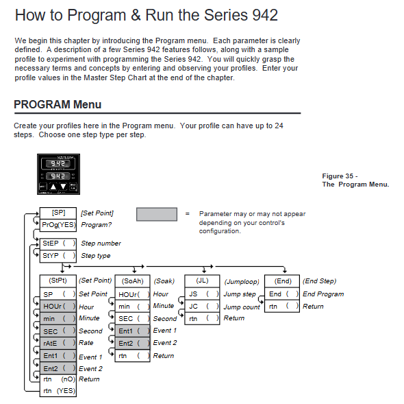
Program structure: Up to 24 steps, each step can be selected from four types: StPt (Setpoint Slope), SoAh (Constant Temperature Holding), JL (Jump Loop), and End (Program End), supporting multiple program concatenation (a new program can start after one End step).
Programming entrance: Select Prog=YES from the Operation menu to enter the Program menu. Press the StEP parameter to select steps (1-24), and press StYP to select the step type.
Detailed explanation of four step programming methods
1. Set point step (StPt)
Core parameters:
SP: Target Set Point (rL~rH).
Time basis (PtYP=ti): HOUr/Min/SEC, total time is the sum of the three (0-23h59m59s).
Rate basis (PtYP=rAtE): rAtE, temperature change rate (0-360 ° F/min or 0-200 ° C/min).
Ent1/Ent2: On/Off status of event 1/2, displayed only when Ot3/Ot4 is set to Ent.
Example: Step 1 is set to StPt, SP=75 ° F, Min=0, SEC=1, Ent1=OFF, achieving the initial setting of reaching 75 ° F within 1 second.
2. Constant temperature step (SoAh)
Core parameters: HOUr/Min/SEC (constant temperature duration), Ent1/Ent2 (event switch), no SP parameter (inherited from the previous set point).
Example: Set Step 3 to SoAh, Min=0, SEC=25, Ent1=On, achieve 25 seconds of constant temperature and trigger Event 1.
3. Jump loop step (JL)
Core parameters:
JS: Jump to the target step (must be smaller than the current step, cannot jump to itself).
Example: Set Step 6 to JL, JS=2, JC=1, implement a jump to Step 2 and repeat once (execute Steps 2-5 twice in total).
4. End step
Core parameters: End (HOLD remains in the last state/OFF closes all outputs/OFFA closes control outputs, retains alarms).
Example: Step 4 is set to End, End=OFF. After the program ends, all outputs are turned off, and ‘lower’ displays’ OFF ‘.
Program Execution and Control
Start program: In the non Setup menu interface, press the HOLD/RUN button, the RUN LED flashes, select the Start Step (StP), then press the HOLD/RUN button to confirm, the RUN LED stays on, and the program starts.
Pause and Resume: Press the HOLD/RUN button once to pause (RUN LED flashes); Press the HOLD/RUN key again to switch to the rESU parameter, and press the HOLD/RUN key to resume operation (only when the program has not been modified).
View operating status: Press the MODE key to switch parameters in the RUN menu, where you can view remaining time (HOUr/Min/SEC), current rate (rAtE), event status (Ent1/Ent2), etc.
Programming Example (Slope Constant Temperature Cycle)
Requirement: Initial temperature of 75 ° F → 25 seconds to rise to 100 ° F (event 1 activated) → 25 seconds constant temperature → 25 seconds to rise to 125 ° F (event 2 activated) → 25 seconds constant temperature → jump to step 1 and repeat twice → maintain the final state.
Step by step SP (° F) Time (minutes: seconds) Ent1 Ent2 JS JC End
1 StPt 75 0:01 OFF OFF – – –
2 StPt 100 0:25 ON OFF – – –
3 SoAh – 0:25 ON OFF – – –
4 StPt 125 0:25 OFF ON – – –
5 SoAh – 0:25 ON OFF – – –
6 JL – – – – 1 2 –
7 End – – – – – – HOLd
Tuning operation (automatic and manual)
Automatic tuning (recommended)
Applicable scenario: Quickly obtain optimized PID parameters after first use and system load changes.
Operation steps:
Enter the Operation menu and find the Aut parameter (displayed only when Ot1=ht).
Press the UP/DOWN keys to select the tuning rate (1 slow/2/3 fast, mostly 2 in most scenarios).
Press the MODE key to start tuning, and the lower display alternately flashes Aut and the current parameter. During tuning, the cooling output is turned off, and the heating output runs at 90% set point ON/OFF.
Complete tuning within 80 minutes, automatically save PID parameters, restore Aut to 0, and return to normal control mode; Modifying the set point during tuning will restart tuning. Press the UP/DOWN key to set Aut=0 to abort (restore the original parameters).
Manual tuning (precise optimization)
Operation steps:
Initialization parameters: Pb1=1, Ct1=5, rE1=rA1=0, CAL=0, Aut=0, set target temperature.
Proportional band (Pb1) adjustment: gradually increase Pb1 until the process temperature stabilizes (initial reset to 0, temperature may deviate from the set point).
Reset/Integral (rE1) Adjustment: Gradually increase rE1 until the temperature begins to oscillate, then slowly decrease until the temperature stabilizes near the set point.
Rate/Differential (rA1) Adjustment: Assuming rA1=1.00 minutes, raise the set point by 20-30 ° F. If the temperature is overshoot, increase rA1 (maximum 9.99) to avoid overshoot and slow response.
Cycle time (Ct1) adjustment: Optimized within the range of 1-60 seconds. It is recommended to choose a longer cycle time for mechanical contactors (to reduce wear) and a shorter time for electronic loads (to improve control accuracy).
Alarm and fault handling
Alarm function operation
Alarm type:
Process alarm (Pr): Based on the absolute temperature threshold (A1LO/A1HI), an alarm is triggered when the temperature exceeds the range.
Deviation alarm (dE): Based on the set point offset (such as+7 ° F/-5 ° F), the alarm threshold synchronously shifts when the set point changes.
Alarm status:
Non Locked (nLA): Automatically resets after the alarm condition disappears.
Lock (LAt): Manual reset is required (first eliminate the alarm condition, then press the HOLD/RUN button).
Alarm indication: The lower display alternately flashes “LO”/”HI” and the current parameter, the L3/L4 LED lights up, and the auxiliary output triggers (N.O. closed/N.C. open).
Common faults and solutions
Fault symptoms, error codes, possible causes, and solutions
The upper display shows “—-“, the lower display shows Er7 Er7 A/D overflow, the sensor is open/polarity reversed, check the sensor wiring (positive and negative poles, terminal contact), confirm that the In parameter is consistent with the sensor type
The upper display shows “—-“, the lower display shows Er1/Er2 Er1/Er2 sensor over/under range, A/D fault confirms that the sensor range matches rL/rH, checks if the sensor is damaged, and recalibrates the A/D
Pause during program operation – gSD deviation window enabled, adjust gSD value if temperature exceeds ± gSD range (increase window), check if heating/cooling system is normal, eliminate load interference
Communication failure – baud rate/protocol/address mismatch, wiring error. Confirm that bAUd (baud rate), Prot (protocol), Addr (address) in the Setup menu are consistent with the host, and check the communication line wiring (RS-485 requires corresponding A/B lines)
Large temperature measurement error – sensor wiring error, calibration offset, environmental interference. Reconnect and confirm sensor type, enter Cal menu to adjust CAL offset, check signal line shielding and grounding
Output unresponsive – Set the set point to OFF, configure the output type incorrectly, adjust the SP to the rL~rH range for load faults, confirm the Ot1/Ot2 parameters (ht/CL), check if the load impedance matches the output type, and test if the load is normal
Calibration operation (accuracy calibration)
Calibration prerequisite
Only enter under LOC parameters and require precise equipment (such as precision millivolt source, resistance box, voltage/current source, 4.5-inch multimeter).
Backup all parameters (Setup/Operation/Program) before calibration, turn off all outputs during calibration (except for process outputs), and automatically save calibration values when the RUN LED lights up.
Core Calibration Process (Taking Thermocouples as an Example)
Wiring: Connect the precision millivolt source to terminals 7 (+) and 9 (-), connect to AC power and ground.
Preheating: Power on for 15 minutes, enter the Cal menu (hold down the UP/DOWN key under LOC parameters), press the MODE key to select the tCL parameter.
Low range calibration: The millivolt source outputs 0.00mV, and after stabilizing for 10 seconds, press the MODE button.
High range calibration: J-type thermocouple outputs 50.00mV, R/S/B type outputs 16.035mV. After stabilizing for 10 seconds, press the MODE button.
Compensation calibration: Disconnect the millivolt source and connect the J-type reference compensator (32 ° F/0 ° C). After stabilizing for 10 seconds, press the HOLD/RUN button to exit the RUN mode and complete the calibration.
Other calibrations (RTD/process input/output)
RTD calibration: Use a 1K Ω precision resistance box to connect terminals 4-6, and input low/high resistance values according to the rLO/rHI parameters (refer to Table 7 in the manual).
4-20mA input calibration: Short circuit terminals 2-3, output 4.00mA (4A parameter) and 20.00mA (20A parameter) from the current source, and calibrate sequentially.
Process output calibration: Connect a multimeter and a matching resistor (such as 4-20mA connected to a 470 Ω resistor), adjust the output to the target value (such as 4.00mA/20.00mA) according to the O1LO/O1HI parameters.
Maintenance and Precautions
routine maintenance
Regular inspection: Check whether the sensor wiring is loose or corroded, whether the panel screws are tightened, and whether the heat dissipation is good.
Battery replacement: Lithium batteries (with backup operating parameters) have a lifespan of about 10 years. In case of abnormal Pout or Run parameters, they need to be returned to the factory for replacement.
Cleaning and maintenance: Wipe the panel with a dry soft cloth to prevent liquid from seeping into the interior of the equipment; Avoid using in damp, dusty, and corrosive environments.
Safety precautions
Disconnect the power supply before wiring, strictly follow NEC and local electrical regulations, and ensure reliable grounding (to avoid electric shock and interference).
The front plate screws should only be rotated 90 °, and excessive force should be avoided to avoid damaging the chassis locking structure.
Mercury relays are only suitable for resistive loads and are prohibited from being used for inductive loads (such as motors without buffering).
Calibration and maintenance must be carried out by professional personnel, and unauthorized disassembly of the equipment casing is prohibited (which may affect warranty).
The Watlow Series 988 controller is a 1/8 DIN microprocessor based temperature/process controller that integrates multiple functions, covering four models: 986, 987, 988, and 989. It has flexible configuration, compact size, and high durability, and can adapt to various temperature and process control scenarios. It supports multiple input/output options and complex control algorithms.
Core characteristics of controller
1. Hardware and functional highlights
Compact design: 1/8 DIN size, integrated with rich functions, balancing flexibility and durability
Control capability: Supports single unit cascade control, covering various process variables such as temperature, pressure, flow rate, etc
Featured features: including heater current monitoring, remote setpoint input, proportional control, and sliding line feedback valve control
Algorithm and Alarm: Equipped with extended self-tuning function, enhanced alarm function, and multiple unique control algorithms
2. Model coverage
When referring to “Series 988”, it includes both horizontal and low-voltage versions (986, 987, 988, 989)
There are differences in power specifications and installation methods among different models (such as 986/988 for vertical installation and 987/989 for horizontal installation)
Installation and hardware settings
1. DIP switch configuration
Number of switches: Depending on the model, the controller contains 1-6 DIP switches inside
Core functions: Configure input sensor types, provide power for external signal conditioners, lock some functions of the front panel
Operation steps: Press the release tabs on both sides/top of the panel to remove the controller chassis. After setting the switch as shown in the diagram, reset the chassis and ensure that all four tabs are securely fastened
2. Panel installation
Installation preparation: Contact the back of the panel and cut the panel cut according to the size requirements (recommended to use Greenlee 1/8 DIN hydraulic kit)
Installation steps: Slide the controller housing into the panel cut, ensure that the sealing gasket is flat, install the bracket and tighten the screws (to avoid deformation of the housing due to over tightening), and finally insert the chassis and clamp it tightly
Sealing requirements: Strictly follow the installation process to ensure NEMA 4X sealing level and prevent equipment damage
3. Wiring specifications
Safety prerequisite: Follow the National Electrical Code (NEC) safety standards to avoid the risk of electric shock
Core wiring: including power wiring (100-240V AC/DC or 24-28V AC/DC), sensor wiring (thermocouples, RTDs, etc.), input/output wiring (supporting up to 4 inputs and 4 outputs)
Isolation requirement: Optical isolation (500V AC isolation barrier) is used between analog input and controller output/digital input to avoid grounding loops
Operation interface and menu navigation
1. Front panel buttons and display
Core keys: Up arrow key (increase value), Down arrow key (decrease value), Mode key (confirm/switch menu), Display key (return to display loop), Auto/Manual key (mode switch/alarm reset)
Display function: upper displays actual process values, parameter values, or error codes; Lower displays set points, deviations, percentage outputs, etc; L1-L4 LED indicates whether the corresponding output is activated
Special operation: Press the up and down arrow keys simultaneously for 3 seconds to enter the settings menu, and press again for 3 seconds to enter the factory menu (which can be locked through DIP switch)
2. Core menu system
(1) Display Loop
Definition: The controller defaults to the “home” state and automatically returns after 1 minute of inactivity. Pressing the display button can return at any time
Display content: including input 1 reading, set point 1, input 2 reading (if equipped), deviation value, percentage output, temperature unit, etc
(2) Setup menus
Entry method: In the display loop state, press the up and down arrow keys simultaneously for 3 seconds
Includes menus: Input menu (InPt), Output menu (OtPt), Global menu (GLbL), Communication menu (COM, visible only for models equipped with communication function)
Operation rules: Output disabled during menu navigation. Use the up and down arrow keys to select the menu, and the mode key to step through the menu options
(3) Operation menus
Entry method: Press the mode key while displaying the loop state
Includes menus: System Menu (SYS), PID A Menu (PidA), PID B Menu (Pidb)
Core functions: Set second set point, idle set point, alarm trigger value, start self-tuning, etc
(4) Factory menus
Entry method: In the settings menu state, continue pressing the up and down arrow keys for 3 seconds
Includes menus: Panel Lock Menu (PLOC), Diagnostic Menu (diAg), Calibration Menu (CAL)
Restriction: When the hardware lock DIP switch is turned on, the menu cannot be accessed
Core functional configuration
1. Input/output configuration
Input settings: Select sensor type (thermocouple, RTD, 4-20mA, etc.), set decimal places, range upper and lower limits, calibration offset
Output settings: Configure output response mode (heating/cooling, alarm activation/deactivation), set lag value, alarm type (process alarm, deviation alarm, rate alarm)
2. Control mode and algorithm
Control type: supports normal control, cascade control, proportional control, differential control
Algorithm selection: Single group PID, proportional/differential control (with manual reset), dual group PID, duplex (heating/cooling) control can be selected
Self tuning function: supports automatic tuning of PID parameters, which needs to be started in the system menu. During the tuning process, the controller enters switch control mode
3. Alarm and error handling
Alarm function: Output 2-4 can be configured as an alarm, supporting lock type (manual reset required) and non lock type (automatic reset after fault relief)
Error code: including A/D conversion error, sensor over/under range error, ambient temperature error, etc. When an error occurs, the controller automatically switches to manual mode and maintains the preset output
Detailed explanation of software functions
1. General software functions
Core functions: including burst fire, communication function, dead zone control, digital events, heater current monitoring, input filtering, linearization, ramp to set point, remote set point, retransmission function, sliding line feedback, etc
Application scenario: Sudden ignition is suitable for zero crossing solid-state devices; Dead zone control prevents simultaneous activation of heating/cooling outputs; Sliding line feedback can control valve position
2. Enhanced software features (models equipped with enhanced software only)
Cascade control: precise control is achieved through two control loops (outer loop monitoring process values, inner loop monitoring heat source temperature) to reduce overshoot
Dual PID group: supports two independent PID parameters, which can be switched based on process values, setpoints, or event inputs
Proportional control: controlling the proportional value of one process variable to another, suitable for material mixing scenarios
Maintenance and Support
1. Calibration and Diagnosis
Calibration requirements: Factory calibrated. If regular calibration is required, please refer to the dedicated calibration manual
Diagnostic function: The software version, serial number, ambient temperature, A/D count, test display, and output functions can be viewed through the diagnostic menu
2. Warranty and Returns
Warranty period: 36 months warranty (from the date of first purchase and use), covering material and process defects
Return process: Contact customer service first to obtain a Return Merchandise Authorization (RMA) number. For returned products, prepaid shipping fees are required. For unused products, a 20% restocking fee may be charged
3. Technical support
Support time: 7am to 5pm Central Time in the United States
Support preparation: When contacting, please provide the controller model (12 digit number, located on the shell sticker and circuit board), user manual, configuration information, and diagnostic menu readings
Key Appendix Information
1. Specification parameters
Input type: Supports process signals such as J/K/T/N/R/S/B thermocouples, 100 Ω RTDs, 4-20mA, 0-10V, etc
Output options: Solid state relay (0.5A), electromechanical relay (5A), open collector, process output (4-20mA/0-10V), etc
Accuracy: ± 0.1% ± 1 LSD of full scale (ambient temperature 25 ℃± 3 ℃, rated voltage ± 10%)
2. Glossary of Terms
Core terms: including definitions of professional terms such as annunciator, burst fire, cascade control, PID (proportional integral derivative), dead band, etc
Core positioning: A DIN rail mounted temperature regulation controller that supports thermocouple or RTD sensor input, with both DIN rail quick installation and embedded installation methods. Designed for various safety application scenarios, it can achieve high/low limit temperature control and is suitable for industrial heating equipment, commercial cooking equipment and other scenarios that require temperature safety protection, such as ovens, reactors, heaters, etc.
Core Features and Advantages
Flexible and convenient installation: Supports DIN EN50022 standard 35mm × 7.5mm rail installation, which can be completed with simple manual tools. Embedded installation can also be selected to adapt to different installation environment requirements.
Diverse control modes: The factory can preset high/low limit control modes, support manual or automatic reset after power failure, and meet different safety control logics; Equipped with temperature over limit latch alarm function, requiring manual reset to enhance safety and reliability.
Intuitive and easy to understand operation: equipped with output status LED indicator lights, providing real-time feedback on working status; Support built-in/remote adjustable or fixed setpoints, calibrated dial to compensate for sensor nonlinearity errors; Simultaneously compatible with both Celsius (° C) and Fahrenheit (° F) temperature scales, suitable for different usage habits.
Comprehensive safety protection: equipped with thermocouple and RTD disconnection protection function, automatically cutting off output in case of sensor failure to avoid equipment damage; Obtained multiple certifications such as CE and FM Class 3545, compliant with EN61010 safety standards, EN61326 industrial electromagnetic compatibility standards (Class B emission), installation category II, pollution level 2, suitable for specific scenarios such as commercial cooking.
Strong adaptability: Supports multiple thermocouple (E, J, K, T type, etc.) and RTD (100 Ω, 1000 Ω) inputs, with optional power supply voltages of 24VAC, 120VAC, 230-240VAC to meet different on-site power supply and sensing needs.
Product Technical Specifications
(1) Control and operation specifications
Control mode: The factory can choose high limit or low limit control; The power-off reset mode can be selected manually or automatically; When the temperature exceeds the limit (too high/too low), a latch alarm is triggered and manual reset is required; Support built-in reset switch or external reset switch provided by the user.
Operation interface: LED indicator light displays output status (power on/off); Adjustable set point (built-in/remote) equipped with calibration dial to compensate for sensor nonlinearity; Fixed set point factory calibration according to user specified values; Dual temperature scale (° C/° F) switching.
(2) Enter specifications
Sensor type: Supports thermocouples (E, J, K, T, etc.) or platinum resistance RTDs, thermocouples have automatic cold junction compensation function, and can choose isolation or grounding type; RTD supports 2-wire or 3-wire system, calibrated at 100 Ω @ 0 ° C, and conforms to the 0.003850 Ω/Ω·° C curve.
Input protection: thermocouple and RTD disconnection protection function, automatically cuts off the output when the sensor is disconnected, preventing equipment from losing control.
Measurement range: Depending on the sensor type and model configuration, for example, E-type thermocouple 0-799 ° C (32-1470 ° F), J-type thermocouple 0-315 ° C (32-600 ° F), T-type thermocouple -200-350 ° C (-328-662 ° F); RTD measurement range -73-600 ° C (-100-1112 ° F), etc., fixed set points can be customized according to user needs (such as 200 ° C, 350 ° C, etc.).
(3) Output specifications
Output type: 8A electromagnetic relay, Form C (single pole double throw, SPDT), rated load: 8A@240VAC (obstructive) 8A@28VDC (Resistive), with a rated load of 275VA, can directly drive small heating equipment, contactor coils, and other loads.
Load protection: When switching inductive loads (such as relay coils, solenoid valves, etc.), an RC suppressor (Watlow recommended model Quencharc, part number 0804-0147-0000) needs to be installed to avoid electromagnetic interference damaging the controller.
(4) Accuracy and stability
Calibration accuracy: The adjustable set point (built-in/remote) is within ± 1% of the range at an ambient temperature of 25 ° C ± 3 ° C (77 ° F ± 5 ° F) and a rated line voltage of ± 1%, with a minimum range of 540 ° C (1000 ° F); The fixed set point has an error of ± 6 ° C/± 10 ° F under the same environmental and voltage conditions.
Setpoint accuracy: The precision of the adjustable set point dial is ± 3%.
Temperature stability: When the thermocouple is input, for every 1 ° C change in ambient temperature, the input reference drift typical value is 9 µ V/° C (5 µ V/° F); When inputting RTD, for every 1 ° C change in ambient temperature, the typical drift value is 0.2 ° C/° C (0.2 ° F/° F).
Voltage stability: For every 1% change in rated line voltage, the range drift is ± 0.01% (minimum range 540 ° C or 1000 ° F).
(5) Power and environmental specifications
Power parameters: Supports 24VAC (+10%/-15%), 120VAC (+10%/-15%), 230-240VAC (+10%/-15%), frequency 50/60Hz, maximum power consumption 10VA, power type needs to be specified by model (such as 1=120VAC, 2=230-240VAC, 3=24VAC).
Environmental conditions: working temperature 0-55 ° C (32-131 ° F), storage temperature -20-85 ° C (-4-185 ° F); Relative humidity 0-90% (non condensing), suitable for most industrial and commercial environments.
Terminal specifications: Captive screw cage clamping connection, supports maximum 4mm (0.155 inch) screwdriver head operation, compatible with 14-30 gauge wires.
Installation method: DIN rail installation (compatible with 35mm × 7.5mm rails) or embedded installation. Embedded installation requires drilling two 5mm (0.19 inch) holes on the panel and fixing them with # 8-32 screws.
Installation and Wiring Guide
(1) Installation process
1. Sub Panel Mounting
Attention: FM certification requires that limit switches be appropriately closed to reduce arbitrary adjustments to the set temperature.
Step 1: Use the controller as a template and mark two installation hole positions on the panel (refer to the hole size in Figure 2a of the document).
Step 2: Drill two 5mm (0.19 inch) diameter holes at the marked location.
Step 3: Use two # 8-32 screws to secure Series 146 to the panel.
2. DIN Rail Mounting
Step 1: Align the upper mounting clip of the controller with the upper edge of the DIN rail (refer to Figure 2b in the document).
Step 2: Press firmly on the upper edge of the front part of the controller, and the controller will be firmly fixed on the guide rail in a “snap” manner; If it cannot be fastened, check if the guide rail is bent. The clamping distance range of the guide rail is 34.8mm (1.37 inches) to 35.3mm (1.39 inches).
3. Disassemble from DIN rail
Step 1: Use your fingers to hold down the release lever at the bottom of the controller.
Step 2: Gently press the top of the controller (above terminals 1-9) and pull the release lever forward to remove the controller.
(2) Wiring specifications
1. General wiring rules
Use sensor types that match the device label model to ensure correct polarity of thermocouples or RTDs.
Thermocouples should be insulated from the installation surface during installation to avoid input errors caused by thermal conduction; Thermocouple leads should be made of twisted pair wires, wired separately, and kept away from other circuits.
In environments with severe electromagnetic interference (such as frequent switching of contactors, motors, and solenoid valves), shielded thermocouple leads should be used, and the shielding layer should only be grounded at the sensor end.
All wiring and fuse configurations must comply with the National Electrical Code (NEC NFPA70) and applicable local regulations; The independent load voltage needs to be fused on the L1 (live) side and connected to the common terminal (COM) of the relay.
It is recommended to install a power isolation switch near the controller to cut off the power supply in case of controller failure; The lead resistance of a 2-wire RTD can introduce errors (every 1 Ω lead resistance leads to additional errors). It is recommended to use a 3-wire RTD to compensate for lead resistance, and the three extension wires must have the same resistance (same wire gauge, copper stranded wire).
2. Power wiring
The power supply type is specified by the model: 120VAC corresponds to model 146_ -1_ -00000 230-240VAC corresponds to 146-2_ -0000, 24VAC corresponds to 146-3_ -0000.
Warning: To avoid the risk of electric shock, wiring must comply with national electrical safety standards. All wiring and fuses must comply with NEC and local regulations, otherwise it may cause equipment damage, property damage, or personal injury; The controller should be installed in an inconspicuous location to prevent unauthorized personnel from adjusting the set point. Only authorized personnel can operate the set point change, and unauthorized operation may cause safety risks; Applying incorrect voltage can cause irreversible damage to the controller.
3. Input wiring
Thermocouple wiring: Connect the positive and negative poles to the corresponding terminals as shown in Figure 3b of the document to ensure that the cold end compensation function is normal. Isolation and grounding thermocouples should be wired according to the model requirements.
RTD wiring: Refer to Figure 3c in the document for the wiring methods of 2-wire and 3-wire RTDs. The three leads of the 3-wire RTD need to have the same resistance. When wiring, pay attention to the correspondence between terminals S1 and S3 to ensure that the calibration curve matches (0.003850 Ω/Ω·° C).
4. Output wiring
The wiring of the electromagnetic relay (Form C type) should refer to Figure 3d in the document. The load should be connected in series between the normally open (NO) or normally closed (NC) terminal and the common terminal (COM). A fuse (recommended specification 1A) should be installed on the L1 side, and an RC suppressor should be connected in series for inductive loads.
5. Remote reset wiring
The remote reset switch is provided by the user, and the wiring method refers to Figure 3e in the document (terminals 13, 15, 16, 17, 14). Only the momentary switch meets FM certification requirements, and remote reset may affect the validity of FM certification.
6. System wiring example
Typical system wiring includes components such as power isolation switches, fuses, controllers, sensors, loads (heaters), contactors, solid-state relays, etc. Please refer to the two system wiring schemes in Figure 4 of the document to ensure that the power supply, input, output, and reset circuit wiring are complete and comply with safety regulations.
Model selection and order information
(1) Model Structure
The model format is 146E – (1/2/3) (100-999) – (1/2/3/4) (any three letters/numbers), and the meanings of each part are as follows:
146E: Product series and output type, E=8A electromagnetic relay (Form C type).
Line voltage code: 1=120VAC, 2=230-240VAC, 3=24VAC.
Input and Range Code: Represents sensor type and measurement range, for example:
E-type thermocouple: 619=0-799 ° C (32-1470 ° F).
J-type thermocouple: 601=0-315 ° C (32-600 ° F), 602=0-750 ° C (32-1382 ° F), 615=fixed 315 ° C (600 ° F), etc.
K-type thermocouple: 603=0-1250 ° C (32-2282 ° F), 611=0-600 ° C (32-1112 ° F), etc.
T-type thermocouple: 629=-200-350 ° C (-328-662 ° F), 632=fixed -75 ° C (-103 ° F), etc.
RTD: 101=-73-600 ° C (-100-1112 ° F, 100 Ω), 104=-73-600 ° C (-100-1112 ° F, 1000 Ω), 106=fixed 200 ° C (392 ° F), etc.
Confirm the on-site power supply voltage and select the corresponding line voltage code (1/2/3).
Select the sensor type (thermocouple/RTD) and corresponding range code based on the temperature measurement range and accuracy requirements, and specify the target temperature for the fixed set point.
Select the limit mode (high/low limit) and power-off reset mode (manual/automatic) according to safety control requirements.
Select remote options according to installation and operation requirements (built-in/remote setpoints, whether remote reset is required).
The warranty period for electromagnetic relays is usually 100000 closing operations, and the service life needs to be evaluated in conjunction with the load switching frequency.
Troubleshooting and Maintenance
(1) Common faults and solutions
Possible causes and solutions for the fault phenomenon
Load cannot start sensor open circuit maintenance or replacement of sensor
Check if the fuse, circuit breaker, load, and wiring of the load circuit are normal for an open circuit
Check the AC input connection according to the “Power Wiring” section (page 3) if it is not connected or connected incorrectly. If it is not connected, reconnect it
The load cannot be turned off. Connect the thermocouple correctly by reversing the thermocouple according to the “Input Wiring” section (page 4)
Controller failure cuts off the power supply of the controller and removes it from the system, only supplying power to the system; If the load is turned off, it indicates a controller malfunction and needs to be returned to the factory for repair; If the load is still running, it indicates that there are other faults in the system. Please contact the factory for consultation
(2) Maintenance
Regularly check whether the wiring terminals are loose, whether the sensors are damaged or aged, and ensure reliable connections.
Keep the controller clean, avoid dust and oil accumulation, and stay away from corrosive environments and severe vibrations.
Regularly verify the accuracy of set points and the reliability of output actions, and promptly troubleshoot sensor or wiring issues if any abnormalities are found.
Product positioning: Industrial grade PID controller, suitable for basic temperature control and limit monitoring scenarios, supporting composite functions such as PID control, limit detection, and multi class alarms.
Model specifications: available in two panel sizes: 1/32 DIN (PM3) and 1/16 DIN (PM6), supporting AC/DC dual power supply mode and compatible with multiple input/output configurations.
Core advantages: simple and easy to operate menu, PID self-tuning function, multi bus communication support, FM certified over/under temperature protection, three-year warranty, and features such as touch safe packaging, waterproof and dustproof (NEMA 4X/IP66/IP67).
Product Features and Technical Parameters
(1) Input function
Analog input
Type and Range: Supports thermocouples (such as J, K, T, E, etc., with different measurement ranges for different types, such as J type -346 to 2192 ° F, i.e. -210 to 1200 ° C), RTDs (calibrated at 100 Ω, 1k Ω, 0 ° C, in accordance with DIN curves, 2-3 wire system, 20 Ω total lead resistance, typical excitation current 0.09mA, lead resistance per ohm may cause 0.03 ° C reading deviation), thermistors (5k Ω, 10k Ω, 20k Ω, 40k Ω), process signals (voltage 0-10VDC, input impedance 20k Ω; current 0-20mA, input impedance 100 Ω); Millivolt 0-50mVdc, input impedance 20k Ω), 1k Ω potentiometer, and all analog inputs can be scaled to meet different measurement requirements.
Configuration requirements: Sensor type (sEn), linearization (Lin, for thermocouples), number of leads (rt.L, for RTDs), unit, scaling high and low values (s.Lo, s.hi), range high and low values (r.Lo, r.hi) and other parameters need to be configured in the “Setup Page – Analog Input Menu” to ensure compatibility with the connected input device. For example, thermocouples should pay attention to polarity (negative pole is usually red, connected to S1 terminal), and the extension wire should be made of the same material as the thermocouple to reduce errors; The S1 lead (usually white) of a 3-wire RTD needs to be connected to R1 and/or R2 terminals, and the resistance of the three leads must be consistent to ensure accuracy.
Performance indicators: thermocouple input impedance>20M Ω, maximum source resistance 2k Ω, with 3 µ A open circuit sensor detection function; The input accuracy of RTD is affected by lead resistance and needs to be compensated through calibration; The scaling range of process input can be set according to actual needs, such as 4-20mA corresponding to 0-100% humidity, etc.
Digital input
Hardware configuration: The model with Digital Input/Output (DIO) hardware includes two sets of terminals (5 and 6), each set can be configured as an input or output, and needs to be set through the “Direction” parameter in the “Setup Page Digital Input/Output Menu” (input can choose voltage input or dry contact input).
Input characteristics: When voltage is input, the maximum input voltage is 36Vdc, the activation voltage is>3Vdc (0.25mA), and the non activation voltage is<2VDC; When using dry contact input, the activation resistance is less than 100 Ω, the non activation resistance is greater than 500 Ω, and the maximum short-circuit current is 13mA. The update rate is 10Hz, which can be used to detect equipment start stop status, external trigger signals, etc.
Special Input: The Reset button on the front of the controller can be configured as a digital input through the “Digital Input Function” parameter in the “Setup Page Reset Key Menu” to achieve function switching, such as limit reset, alarm mute, etc.
(2) Output function
Output type and characteristics
Mechanical relay: Form C type (output 1, 3), rated load 5A@240Vac Or 30Vdc (resistive), minimum load 20mA@24V , 125VA pilot duty at 120/240Vac, 25VA pilot duty at 24Vac, with a lifespan of 100000 cycles (rated load), supporting AC/DC loads, no power output, requiring external power supply; Form A type (outputs 2 and 4) has parameters similar to Form C type, with only normally open contacts. Output 2 is default bound to the limit function and serves as the main output for limit protection.
Solid state relay (SSR): Form A type (output 3, 4), rated load 0.5A@20-264Vac (Resistive), 20VA pilot duty at 120/240VAC, optocoupler isolation, contactless suppression, maximum off state leakage current of 105 µ A, minimum holding current of 10mA, only supports AC load, no power output.
Switching DC/collector open circuit output: Supports outputs 1, 3, and 4, with a maximum open circuit voltage of 22-25Vdc, a maximum current of 30mA for a single output, and a maximum total current of 40mA for paired outputs (1&2, 3&4). Typical driver 4.5Vdc@30mA Short circuit current limit<50mA (NPN transistor current), can drive external solid-state relays, supports multiple sets of DIN-A-MITE relays in parallel/series (such as 1 pole up to 4 sets in parallel/series, 2 poles up to 2 sets in parallel/series, 3 poles up to 2 sets in series).
Universal process output: Only supports 3 outputs, can be configured as voltage (0-10VDC, minimum load 1k Ω) or current (0-20mA, maximum load 800 Ω) output, with scaling function (s.Lo, s.hi, r.Lo, r.hi), can be used to retransmit process values or set values, output accuracy ± 15mV (voltage), ± 30 µ A (current), temperature stability 100ppm/° C, need to configure parameters such as type (o.ty), function (fn), and retransmission source (r.Sr) in the “Setup Page Output Menu”.
Output configuration logic: All outputs need to be assigned functions (such as limit, alarm, retransmission, etc.) and function instances (such as alarm 1-4, limit 1, etc.) in the corresponding menu (Output Menu or Digital Input/Output Menu) of the “Setup Page”. For example, output 1 can be configured as “Alarm 1” and output 2 can be fixed as “Limit”; Support multiple outputs associated with the same functional instance, such as alarm 2, which can simultaneously trigger output 1 (indicator light) and output 5 (buzzer).
(3) Core control and protection functions
PID control: supports hot/cold control, switch control, P, PI, PD, PID control algorithms (not specific to limit controllers), with automatic tuning function, can be started through “Operations Page” or configuration software, sampling rate input 10Hz, output 10Hz, control accuracy is affected by input sensor accuracy, calibration status and load characteristics, calibration accuracy is ± 0.1% range ± 1 ° C (0.2% for S-type thermocouples, 0.2% for T-type thermocouples below -50 ° C) at rated ambient temperature (25 ° C ± 3 ° C) and rated line voltage, minimum range 1000 ° F (540 ° C), maximum temperature stability ± 0.1 ° F/° F (± 0.1 ° C/° C) Environmental temperature rise.
Limit protection: As the core function, it supports high/low limit or dual limit monitoring. The limit upper and lower limits (Lh. s, LL. s), hysteresis value (L.hy, 0.001-9999 ° F/° C, default 3 ° F or 2 ° C), and limit sides (L.sd, high, low, or dual sides) can be set in the “Setup Page Limit Menu”; When the process value exceeds the limit range, output 2 (Form A relay) loses power, cuts off the load power supply, and maintains a locked state, requiring manual reset (through the Reset button, digital input, or communication command); Support limit reset source configuration (sfn. a, such as digital input, function keys) to ensure that normal operation can only be restored after troubleshooting.
Alarm function: Supports 4 sets of alarms (1-4), which can be configured as process alarms (high/low alarms, deviation alarms, etc.). Set the alarm type (a.ty), source (sr.a, such as analog input 1-2), upper and lower limits (a.hi, a.Lo), hysteresis value (a.hy), logic (a.Lg, power on alarm or power off alarm), latch (a.La, whether to manually clear), blocking (a.bL, whether to block alarm when starting or setting value changes), mute (a.si, whether to support mute), delay time (a.dL, 0-9999 seconds) and other parameters in the “Setup Page Arm Menu”; When an alarm is triggered, it can be notified through output actions (such as indicator lights, buzzers) or communication signals. Locked alarms need to be cleared through the “Clear Alarm (a.CLr)” command, and silent alarms need to pause output through the “Silence Alarm (a.sir)” command.
(4) Communication function
Support protocols and ports
Modbus RTU: Supports EIA-485 (Port 1/2) and EIA-232 (Port 2), with Port 1 supporting Standard Bus by default and switchable to Modbus RTU; Modbus addresses 1-247 (Standard Bus addresses 1-16), baud rates of 9600, 19200, 38400bps, parity bits none/odd/even, data bits 8, stop bit 1; Supports 16 bit register read and write, floating-point parameters occupy 2 registers, default low byte first (can set “Modbus Word Order” to Lohi or hiLo in the “Setup Page Communications Menu”); Supports Map 1 (compatible with old models) and Map 2 (compatible with new features), and recommends using Map 2 for new applications.
EtherNet/IP ™ Compared to Modbus TCP: only supported on port 2, requires configuration of IP address (fixed or DHCP), subnet mask, gateway, supports 10/100Mbps Ethernet, and can run both protocols simultaneously; CIP implicit assembly (input/output member count 1-20), explicit communication supports Class/Instance/Attribute addressing, compliant with ODVA standards.
DeviceNet ™: Port 2 support, node addresses 0-63, baud rates 125, 250, 500kbps, supports Quick Connect, CIP implicit assembly input/output members up to 200, explicit communication for configuration and diagnosis.
Profibus DP: Port 2 support, addresses 0-126, maximum baud rate of 12Mbps, supports DP-V0 (cyclic data exchange) and DP-V1 (non cyclic data exchange, used for configuration and diagnosis); GSD file configuration is required, supporting up to 32 devices per network segment, with a maximum transmission distance of 1200 meters (EIA-485), and a terminal resistance configuration option (150 Ω).
Communication configuration and tools: All communication parameters need to be configured in the “Setup Page Communications Menu” (such as protocol, address, baud rate, IP parameters, etc.); Can be accessed through Watlow PM LEGACY ™ The Limit Configurator software (free download from the official website) enables communication between the PC and the controller, supporting online configuration, parameter backup/recovery, device scanning, and other functions; During the communication process, attention should be paid to cable selection (such as using twisted pair for EIA-485, avoiding parallel wiring with power lines), terminal resistance (only network end devices need to be connected to a 120 Ω resistor), and grounding isolation (to prevent grounding loops).
Installation and wiring
(1) Installation process
Panel perforation: The PM3 controller needs to be perforated according to the size on page 6 of the document, and the PM6 controller needs to be perforated according to the size on page 7 to ensure that the controller can be smoothly embedded into the panel.
Component disassembly: Remove the green terminal connector and installation ring assembly to avoid damaging the components during installation.
Controller embedding: Insert the controller into the opening from the front of the panel. Taking PM6 as an example, ensure that the installation direction is correct.
Installation ring fixation: Move the installation ring base plane forward, with the screw opening facing the side, and slide it over the back of the controller; Slide the installation bracket over the controller again, aligning the screws with the base, and gently push until the hook clicks into the slot of the housing; Finally, use a Phillips screwdriver to tighten the two # 6-19 x 1.5 inch screws with a torque of 3-4 inch pounds, ensuring that the device is flush with the panel.
Terminal reset: Reinstall the terminal connector to its original position to complete the installation.
Installation spacing requirements: 1/32 DIN (PM3) recommends a panel spacing of 44.96-45.47mm (1.77-1.79 inches), a minimum panel thickness of 21.6mm (0.85 inches), and a panel thickness range of 1.53-9.52mm (0.060-0.375 inches); 1/16 DIN (PM6) recommends a panel spacing of 44.96-45.47mm (1.77-1.79 inches), with other thickness requirements consistent with PM3 to ensure heat dissipation and operational space.
(2) Wiring specifications
Power wiring
Low power model (PM6 [L, M] [3,4} _J-A_G _): supports 12-40Vdc, 20-28Vac (50/60Hz), maximum power consumption of 10VA (PM6), power terminals are 98 (ac/dc+) and 99 (ac/dc -) of Slot C, pay attention to voltage polarity, and comply with NEC or local electrical standards to avoid overvoltage or reverse connection damage to equipment.
High power model (PM6 [L, M] [1,2} _J-A_G _): Supports 85-264Vac, 100-240Vac (Semi Sig F47 standard, 50/60Hz), maximum power consumption of 10VA (PM6), power terminals are also 98 and 99 of Slot C, and suitable fuses are required to prevent overload.
Input wiring
Analog input (Slot A): The terminals of universal sensor input 1 include T1, S1, R1 (thermocouple+ RTD S1、 Potentiometer sliding end, S3 (thermocouple – RTD S3、 Current – etc.), wiring needs to be done according to the sensor type, for example, thermocouples need to distinguish between positive and negative poles, and RTD 3-wire system needs to connect S1 to R1/R2; The process input (voltage/current/millivolts) should be wired according to the terminal identification (such as voltage+connected to S1, voltage – connected to S3) to ensure signal integrity.
Digital input (Slot C): The terminals of digital input 5/6 are D5, D6 (signal), and B5 (common terminal). The voltage input needs to be connected to a DC power supply (such as 24Vdc), and the dry contact input needs to be directly connected to an external contact. When wiring, attention should be paid to isolating from other circuits to prevent interference.
Output wiring
Mechanical relay/SSR (Slot A/B): The terminals of Form C relay are L_ (normally open), K0 (common), and J2 (normally closed), while the terminals of Form A relay are L_ (normally open) and K0 (common). The wiring should be based on the load type (AC/DC), and the load current should not exceed the rated value; SSR only supports AC loads, please pay attention to the phase and voltage range.
Switch DC/collector open circuit (Slot A/B): The terminals are W_ (dc+), X_ (dc -, collector open circuit), and Y1 (common), and an external power supply is required to drive the load (such as a solid-state relay) to ensure that the power supply voltage matches the load and avoid short circuits.
Universal process output (Slot B): The voltage output terminals are F3 (-) and G3 (+), and the current output terminals are F3 (-) and H3 (+). The wiring should be based on the configured output type, and the load impedance should meet the requirements (minimum voltage output of 1k Ω, maximum current output of 800 Ω).
Communication wiring
EIA-485 (Slot C/B): The terminals of Standard Bus/Modbus RTU are CC (common) CA(T-/R-)、CB(T+/R+), Twisted pair cables (such as Cat 5) should be used, with a Daisy chain network topology, a maximum of 16 nodes (Standard Bus) or 247 nodes (Modbus), a maximum transmission distance of 1200 meters, and a 120 Ω terminal resistor connected to the end device.
EtherNet/IP ™/ Modbus TCP (Slot B): The RJ-45 interface is wired according to the T568B standard, with pins E1 (white orange, transmit+), E2 (orange, transmit -), E3 (white green, receive+), E6 (green, receive -). The other pins are not used and need to be connected to a 10/100Mbps Ethernet switch.
DeviceNet ™ (Slot B): The terminals are V+(power+), CH (CAN_S), SH (shielded), CL (CAN_L), V – (power -), and shielded twisted pair cables are required. The node address is 0-63, the baud rate is 125/250/500kbps, and the shielding layer needs to be single ended grounded.
Profibus DP (Slot B): The terminals are VP (+5Vdc), B (T+/R+), A (T -/R -), DG (digital ground), trB (terminal resistance B), trA (terminal resistance A), and require Profibus dedicated cables. The end device needs to be equipped with a terminal resistance (150 Ω), address 0-126, and a maximum transmission distance of 1200 meters.
Wiring precautions: All wiring must comply with NEC or local safety standards, and power-off operation is required; The wire specification is 0.0507-3.30mm ² (30-12 AWG) single stranded wire, or two 1.31mm ² (16 AWG) wires, with a terminal torque of 0.56 Nm (5.0 inch pounds); Unused terminals must not be wired to prevent short circuits; Analog inputs, digital I/O, switch DC outputs, and process outputs must be electrically isolated to prevent grounding loops; When switching inductive loads (such as relay coils and solenoid valves), it is necessary to install an RC suppressor (Watlow recommended model 0804-0147-0000) to avoid electromagnetic interference damaging the equipment.
Operation and Configuration Guide
(1) Page navigation and basic operations
page switching
Home Page: By default, it displays process values (PV) and limit states (safE/faiL), which can be returned from any page by long pressing the Reset button for 2 seconds.
Operations Page: Press and hold the Up+Down key for 3 seconds from the home page to enter, displaying parameters that can be monitored/modified such as analog input values, limit status, digital I/O status, alarm status, etc. Use the Up/Down key to switch menus, the Advance key to enter submenus, and the Reset key to return to the previous level or home page.
Setup Page: Press and hold the Up+Down key for 6 seconds from the homepage to enter (hold down continuously until “SEt” is displayed), used to configure input, output, alarm, communication, global parameters, etc. The operation logic is consistent with the operation page, and some parameters need to be restarted to take effect after modification.
Factory Page: Press and hold the Advance+Reset button for 6 seconds from the homepage to enter. It is used for customizing the homepage, calibration, security settings (password/lock), diagnosis, etc. Caution is required when operating, and some functions (such as calibration) require professional personnel to perform.
Button Function
Up/Down keys: Modify writable parameter values (such as limit settings) on the homepage, and switch parameters/options in the menu.
Advance button: Switch display parameters on the homepage (such as low limit → high limit), enter submenus in the menu or confirm the selection.
Reset button: Reset limit (after troubleshooting), clear alarm (latch alarm), return to the previous page, long press for 2 seconds to return to the home page.
Function key (Fn, only 1/16 DIN): a programmable key that can configure functions (such as limit reset, alarm mute, user settings recovery, etc.) in the “Setup Page Function Key Menu”, supporting level triggering or edge triggering.
(2) Key parameter configuration
Home page customization: Enter the “Factory Page Custod Menu (CuSt)” and select 20 parameters to add to the homepage (such as analog input values, limit settings, alarm status, etc.). Parameter instances (such as alarms 1-4) need to be selected separately; Set the number of display pairs (1-10) through “Setup Page Global Menu-d-prs (Display Pairs)”, and set the automatic switching time (0-60 seconds, 0 is not automatic switching) through “d.ti (Display Time)”. Custom homepage parameters will be updated synchronously after modification on the original page (operation page/settings page), and vice versa.
Simulated input configuration (Setup Page Analog Input Menu)
Sensor type (sEn): Select the type that matches the connected device (such as thermocouple J-type, RTD 100 Ω, 0-20mA, etc.), “off” indicates disabling the input.
Linearization (Lin): Only thermocouples need to be set, select the corresponding linearization curve for the thermocouple type (such as J, K, T, etc.).
Scaling and Range (s.Lo/s.hi, r.Lo/r.hi): Process inputs need to be set, for example, 4-20mA corresponds to 0-100 ℃, so s.Lo=4.00mA, s.hi=20.00mA, r.Lo=0.0 ℃, r.hi=100.0 ℃; The scaling value is the input signal range, and the range value is the display/control range. It supports reverse scaling (e.g. 50psi corresponds to 4mA, 10psi corresponds to 20mA).
Filtering (fiL): Set the filtering time constant (0.0-60.0 seconds, default 0.5 seconds) to smooth the input signal, reduce noise interference, and filter without affecting the limit sensor signal.
Calibration offset (i.Ca): Used to compensate for sensor errors or lead resistance, it can be modified in the “Operations Page Analog Input Menu” (-1999.000-9999.000 ° F/° C), with positive offset increasing the input value and negative offset decreasing the input value.
Set Page Limit Menu
Limit Sides (L.sd): Select “high”, “Lo І”, or “both” to determine the upper, lower, or both limits of the monitoring process value.
Limit setting value (Lh. s/LL. s): Set the high/low limit trigger value (-1999.000-9999.000 ° F/° C, default 0.0 ° F or -18.0 ° C), which needs to be set according to process requirements, for example, the high limit of the heating equipment is set to 200 ℃ and the low limit is set to 50 ℃.
Lag value (L.hy): Set the process value deviation required for limit reset (0.001-9999.000 ° F/° C, default 3.0 ° F or 2.0 ° C), for example, if the high limit is 200 ℃ and the lag is 2 ℃, the process value needs to drop below 198 ℃ to reset the limit.
Reset source (sfn. a/si. a): Select the trigger source for limit reset (such as numeric input 5, Function key) and corresponding instance to ensure that the reset operation is effective.
Alarm configuration (Setup Page Arm Menu)
Alarm type (a.ty): Select “off” or “Pr.AL”, process alarms support high/low alarms (set according to a.sd).
Alarm source (sr.a/is.a): Select the input source (such as analog input 1) and instance for alarm monitoring to ensure matching with the controlled object.
Alarm setting value (a.hi/a.Lo): Set the high/low alarm trigger value (-1999.000-9999.000 ° F/° C, default high alarm 300.0 ° F or 150.0 ° C, low alarm 32.0 ° F or 0.0 ° C), which needs to be set according to the process safety range.
Lock and mute (a.La/a.si): When “a.La” is set to “LAt (lock)”, it needs to be manually cleared after the alarm is triggered; When “a.si” is set to “on”, the alarm output can be muted through the Reset key or communication command.
Communication Configuration (Setup Page Communications Menu)
Protocol (pCoL): Select the protocol for port 1 (Standard Bus or Modbus RTU), and port 2 supports Modbus RTU, EtherNet/IP, DeviceNet, Profibus DP depending on the model.
Address and baud rate: Modbus addresses 1-247, Standard Bus addresses 1-16, DeviceNet addresses 0-63, Profibus addresses 0-126; The baud rate should be selected according to network requirements (such as Modbus RTU 9600bps, DeviceNet 250kbps), and all network devices should be consistent.
IP parameters (EtherNet/IP/Modbus TCP only): Set “iP. ∧Џ” to “dhCP (auto fetch)” or “F.Add (fixed IP)”. Fixed IP requires setting ip.f1-ip.f4 (IP address), ips1-ips4 (subnet mask), and ipg1-ipg4 (gateway). After modification, the controller needs to be restarted to take effect.
(3) Calibration operation
Calibration prerequisite: It is necessary to confirm that the input/output readings exceed the accuracy range (such as a large deviation between the simulated input display value and the standard signal source). Before calibration, a standard signal source with higher accuracy than the equipment (such as a high-precision thermocouple simulator, DC power supply), a high-precision measuring instrument (such as a 4.5 bit multimeter), and the controller must be at a stable ambient temperature (25 ° C ± 3 ° C).
Analog Input Calibration (Factory Page Calibration Menu)
Input offset (ELi. o): Connect a low range standard signal (such as a thermocouple 0.000mV, current 0.000mA), read the controller display value, and if there is a deviation from the standard value, adjust “ELi. o” to make the display value equal to the standard value (range -1999.000-9999.000).
Input slope (ELi. S): Connect a high range standard signal (such as thermocouple 50.000mV, current 20.000mA), read the controller display value, and if there is a deviation from the standard value, adjust “ELi. S” to make the display value equal to the standard value (range -1999.000-9999.000). Slope calibration affects the accuracy of the entire range.
Output offset (ELo. o): Configure the output to a low range value (such as voltage 0.0V, current 4.0mA), measure the actual output value with a multimeter, adjust “ELo. o” to make the actual value equal to the set value (range -1999.000-9999.000).
Output slope (ELo. S): Configure the output to a high range value (such as voltage 10.0V, current 20.0mA), measure the actual output value with a multimeter, adjust “ELo. S” to make the actual value equal to the set value (range -1999.000-9999.000).
Calibration precautions: Calibration parameters need to be saved to EEPROM (via “Setup Page Global Menu Usr. s”) to avoid power loss; After calibration, it is necessary to verify the accuracy of multiple intermediate points to ensure that the entire range meets the requirements; Non professionals are not recommended to perform calibration operations, please contact Watlow technical support.
NAE (Network Automation Engine) and NIE (Network Integration Engine) are monitoring devices that support web access and are based on Ethernet. Their core functions are to monitor and control on-site building automation equipment, HVAC equipment, and lighting systems. Unless otherwise specified in the document, the MS-NAE55xx-x and MS-NIE55xx-x series are collectively referred to as NAE55.
Emission compliance requirements
United States: Compliant with FCC Part 15 Class A digital device restrictions, only applicable to commercial environments. If interference occurs in residential environments, users need to resolve it themselves.
Canada: Meets the requirements of the Canadian Interference Equipment Regulations (R è glement sur le mat é riel brouilleur du Canada).
Preparation before installation
Package contains components
1 NAE55 host
1 data protection battery (individually packaged)
1 installation manual
Required materials and specialized tools
4 fasteners for compatible mounting surfaces (M4 screws for Europe, # 8 screws for North America)
2 sections of DIN rails 36 centimeters (14 inches) and above (only for DIN rail installation scenarios)
1 small flathead screwdriver (used to fix the communication cable of the terminal block)
Installation environment requirements
Stay away from corrosive gases and follow the environmental restrictions specified in the technical specifications.
Avoid installing on surfaces that are prone to vibration (such as pipelines) or near electromagnetic interference sources (to prevent interference with communication).
Reserve sufficient space for wiring and terminal connections (refer to size requirements in Figure 2).
The power supply should not be installed below NAE55.
When installing panels/enclosures, it is necessary to avoid sealing the enclosure and ensure that the enclosure walls or transformers do not obstruct the equipment ventilation openings.
Devices that cause the temperature of the NAE55 processor to exceed 77 ° C (171 ° F) must not be added inside the casing (embedded temperature sensor data must be viewed through diagnostic tags).
Installation process
Installation method selection
NAE55 supports three installation methods: wall mounting, DIN rail mounting, and shell mounting. The core operations are as follows:
1. Wall installation (vertical surface)
Mark the four installation hole positions on the wall according to the dimensions in Figure 3 (horizontal installation hole spacing of 317.5mm, vertical installation hole spacing of 63.5mm) or directly using the host as a template.
After drilling, if anchor bolts need to be fixed, they should be inserted into the holes. First, screw the screws into the top two holes, leaving enough space to accommodate the installation feet.
When installing horizontally, hang the top mounting foot of the host on the screw; When installing vertically, the host needs to be held in a fixed position.
Insert the screws into the two holes at the bottom, being careful not to tighten them too tightly (to avoid damaging the mounting feet or housing).
2. DIN rail installation
Install two sections of DIN rails horizontally, with a center to center distance of 125 millimeters (4.9 inches).
Pull the DIN buckle at the bottom of the host to the outer position.
Hang the DIN rail hook on the back of the host onto the rail.
Push the DIN buckle back to its original position and secure the host.
Disassembly steps: First, move the DIN buckle to the outside, and then remove the host from the guide rail.
3. Shell installation
Install the casing according to the manufacturer’s instructions.
Following the “Installation Environment Requirements” and the above installation specifications, fix NAE55 inside the casing.
Special installation requirements
The UL 864 certified models (MS-NAE5510-0U and MS-NIE5510-0U) must be installed inside a lockable housing.
Wiring operation
Precautions before wiring
Before wiring, a data protection battery must be installed (see “Settings and Adjustments” section), and a 24VAC power supply must not be connected.
Only copper conductors are used, and wiring must comply with local, national, and regional regulations.
Do not exceed the electrical rating of the equipment (NAE55 is a low-voltage equipment,<30VAC), and do not connect to high voltage (otherwise the equipment will be damaged and the warranty will be invalidated).
The terminal block key must not be removed, and the terminal plug and socket are designed to be foolproof and can only be correctly connected.
Prevent electrostatic discharge (avoid damaging equipment and void warranty).
The power cord and communication cable should be kept at least 50 millimeters (2 inches) away from the ventilation duct on the side of the equipment.
Reserve a certain degree of slack in the cables, and arrange the wiring neatly to ensure ventilation, LED visibility, and maintenance convenience.
Core wiring steps
Ethernet connection: Insert the Ethernet cable into an 8-pin RJ-45 Ethernet port (supporting 10/100 Mbps).
Building Automation System (BAS) Network Connection:
N2 or MS/TP network: Connect three bus lines to a 4-terminal plug labeled FC A or FC B (Figure 6).
LONWorks compatible network: Connect the bus line to a 3-terminal plug (Figure 7), and there is no polarity requirement for the network wiring.
Note: The N2 and BACnet MS/TP bus protocols are different and cannot be connected to the same FC bus port; If connecting to N2 or MS/TP bus, an End of Life (EOL) switch needs to be set up (see “Settings and Adjustments” section).
Modem connection: If needed, connect the phone line to the MODEM port (built-in modem model), or connect an external modem to the USB A port.
RS-232 serial port connection (if required): Use a 9-pin male to male null modem cable to directly connect to a computer, only for point-to-point protocol (PPP) network connection (Serial A port) or obtaining an IP address (Serial B port).
Power connection: Connect the power cord of the 24VAC transformer to the power terminal block (Figure 8) to ensure that the transformer phases of all network devices are consistent (reducing interference and grounding loop issues).
Different network topology wiring specifications
Core limitations and requirements for network types
The N2 network supports 100 devices on a single bus, with a maximum cable length of 1500 meters without repeaters; Recommended 1.5mm ² (18 AWG) 3-core wire,+/- bus must be twisted pair
BACnet MS/TP network supports 100 devices on a single FC bus, with a cable length of 1500 meters without repeaters; Recommended 0.6mm (22 AWG) 3-core shielded twisted pair cable
Ethernet network star topology (requiring network hub/switch), with a maximum of 100 devices connected to a single site
LONWorks network bus topology stub cable with a maximum length of 3 meters; FTT-10 nodes can have a maximum of 64 (without repeaters) or 128 (with repeaters); Install corresponding terminators according to topology type
Settings and Adjustments
Install data protection battery
Remove the battery and open the battery compartment cover on the device (Figure 1).
Connect the connector of the battery cable to the connector inside the battery compartment.
Place the battery in the compartment and secure it with a battery strap (pass through the hole and fasten to reduce movement).
Cover the cabin and immediately connect the 24VAC power supply (to avoid battery depletion and damage).
Attention: The battery can only provide data protection in the event of a power outage after at least 2 hours of initial charging. Full charging (24 hours) can support three consecutive power outages for protection; The battery model is MS-BAT1010-0, with a service life of 3-5 years (at 21 ° C).
Set End Connection (EOL) switch
The devices at both ends of the FC bus section need to be set as network termination devices, and each FC port of NAE55 corresponds to a set of EOL switches:
If NAE55 is an FC bus termination device, set both sets of EOL switches for the corresponding ports to the ON position (default factory ON).
If it is not a terminating device, turn the switch to positions 1 and 2.
Startup and shutdown operations
boot process
Confirm that all wiring is correct and the battery is installed.
Connect the 24VAC power supply, and the device will take up to 5 minutes to start.
Startup completion indicator: The green RUN LED is constantly on, and the red GEN FAULT LED is off.
LED test sequence at startup
After the power is turned on, the PEER COM, RUN, GENL FAULT LEDs (NAE55 also includes FC A, FC B) light up, indicating that the operating system is started.
The above LED is off and the RUN LED is flashing, indicating that the device software is loading.
The LED displays the running status of the device, and if the RUN LED is constantly on, it indicates that the device is ready.
Shutdown process
Disconnect the 24VAC power supply (unplug the power terminal block plug).
The device is powered by a data protection battery and continues to operate for 1-8 minutes (backup volatile data) until the POWER LED goes out.
If the power outage exceeds 48 hours, the data protection battery should be removed after the POWER LED is turned off (to avoid battery depletion and damage).
System restart switch
The System Re Boot switch (Figure 1) can only be pressed when the device is unresponsive and cannot be accessed through the user’s device. Restarting will lose the data saved last time (including alarm, trend, and audit tracking data), and other troubleshooting methods should be attempted first.
Troubleshooting
LED status indication (core reference)
Meaning and handling suggestions for abnormal LED names in normal states
POWER (green) constantly on and off indicates that the device is turned off; Always on indicates power supply from battery or 24VAC
ETHENET (green) flashing off indicates no Ethernet traffic, possibly due to network failure or poor connection
FC A/FC B (green) flashing constantly indicates that the port has defined a controller but there is no communication; Extinguish indicates no controller definition (NIE55 does not have this port)
BATT FAULT (red) is off and constantly on, indicating a battery fault (not connected, unable to charge). If it still lights up after 48 hours, check the connection or replace the battery
GENL FAULT (red) off and constantly on indicates general faults (such as high CPU/memory usage, high temperature, battery failure, etc.)
Common problem handling
Battery failure: Check the battery connection. If the connection is normal but still reports an error, replace the MS-BAT1010-0 model battery.
Communication failure: Confirm that the cable connection is correct, the topology meets specifications, the EOL switch setting is correct, and stay away from electromagnetic interference sources.
High temperature: Check the equipment combination inside the casing to ensure that there are no excessive heating devices and good ventilation.
Technical specifications and ordering information
Core technical parameters
Power requirements: Dedicated 24VAC power supply (North American Class 2, European SELV), 50/60Hz, input voltage 20-30VAC
Maximum power consumption of 50 VA
Working environment 0-50 ° C (32-122 ° F), 10-90% RH (dew point ≤ 30 ° C)
Storage environment -40-70 ° C (-40-158 ° F), ≤ 95% RH (dew point ≤ 30 ° C)
Processor MS-NAE5510-0U/NIE5510-0U uses 300MHz Geode GX1; Other models use 400MHz Geode GX533
512MB Flash non-volatile memory, 256MB DRAM
Dimensions (height x width x depth) 226 x 332 x 96.5mm (8.9 x 13.1 x 3.8 inches)
Protection level IP20 (IEC 60529)
Product and accessory ordering
Core product models (partial)
Product code description
MS-NAE5510-1 supports 2 N2 or BACnet MS/TP buses
MS-NAE5510-0U UL 864 8th edition certification, suitable for smoke control
MS-NAE5520-1 supports 1 LONWorks bus and 2 N2/MS/TP buses
MS-NAETUNL-8 N2 Tunnel Function Enabling Tool
Key components
Product code description
MS-BAT1010-0 Data Protection Battery (Replacement)
AS-XFR100-1 24VAC power transformer (with casing)
MS-SECVT-0 Serial to Ethernet Converter (N2 Tunnel Application)
Note: Add “G” after the product code for the US version, “E” for the European version, and “-701” for repair parts.
Maintenance and Compliance Information
Equipment replacement and registration
After replacing the NAE or adding new devices, it is necessary to update the site registration to ensure that the devices are recognized and communicate properly (refer to the NAE Debugging Guide LIT-1201519).
Compliance certification
United States: UL 916 certification, FCC Part 15 Class A, UL 864 smoke control certification (specific models).
Europe: CE mark, compliant with EMC Directive 89/336/EEC.