Call us 24/7uaedcs@163.com
Welcome to the official website of CNIACS Automation Technology Co., Ltd!
Call us 24/7uaedcs@163.com

Tektronix 5440 oscilloscope

Overview of Instrument Core

(1) Hardware structure

Plugin compartment: There are a total of 3 compartments that can accommodate 5000 series plugins (without N suffix plugins supporting display readings), 2 vertical compartments (left and middle) for amplifier plugins, and 1 horizontal compartment (right) for time base plugins. The combination of plugins determines the functionality of the measurement system.

Key controls:

Display related: INTENSITY adjusts the brightness of the trajectory, READOUT INTENS only adjusts the brightness of the reading part (the reading system fails when counterclockwise to the bottom), FOCUS controls for clear display, and BEAM FINDER compresses the trajectory to the scale range.

Power supply and calibration: The power switch (POWER) controls the power on/off, and the internal calibrator (CALIBRATOR LOOP) provides a square wave signal with a voltage of 400mV (± 1%) and a current of 4mA (± 1%), with a frequency of twice the power supply frequency, for calibration and probe compensation.

External interface: EXT INTENSITY INPUT interface receives Z-axis modulation signals (DC coupling,+5V enhanced brightness, -5V reduced brightness, maximum safe input ± 50V, frequency range DC to 2MHz).

(2) Core functions

Display mode:

Alternate mode: The time base plugin display switch pops up and switches between the activated plugin/channel with each CRT scan, suitable for high-frequency signals.

Chop mode: When the time base plugin display switch is pressed, it electronically switches between channels at a rate of 100kHz, suitable for displaying low-frequency signals or single event phenomena.

X-Y operation: Install 5A series amplifiers or 5B series time base plugins with amplifier channels in the horizontal cabin to receive X signals, and 5A series amplifiers in the vertical cabin to receive Y signals, achieving signal comparison display.

Grating display: Both the left vertical cabin and the horizontal cabin are equipped with 5B series time base plugins. The scanning speed of the vertical cabin is slower than that of the horizontal cabin, and brightness modulation is achieved through EXT INTENSITY INPUT, which can simulate TV display.

Reading System: Only supports 5400 series plugins, displaying alphanumeric information in real-time with analog waveforms on CRT. Each plugin’s reading occupies a fixed position (channel 1 is indexed at the top, channel 2 is indexed at the bottom), displaying up to 6 readings (option 3 can select 8 readings). The reading interruption waveform display is only about 20 microseconds/character.

Operation Guide

(1) First operation process (19 steps in total, with the following key steps)

Plug in preparation: Install 5A series amplifier plugs in the left/middle vertical cabin and 5B series time base plugs in the horizontal cabin.

Power connection: After confirming the operating voltage, turn off the power switch and connect a power source that meets the voltage/frequency requirements.

Initial setup:

Amplifier plugin: Display on, center position, CH1 Volts/Div set as needed, CH1 Variable Volts/Div clockwise to the end (Cal), CH1 Input Coupling set to DC, mode set to CH1.

Time base plugin: Display alternately (button pops up), center position, Main Sec/Div set to 5ms, Variable Seconds/Div clockwise to the end (Cal), Swp Mag turned off (button pops up), Main Trig Level counterclockwise to the end, trigger source selected to the left (or center, if the amplifier is in the middle compartment), coupled with Auto Trig, AC Couple,+Slope, mode set to Main Sweep.

Calibration check: Connect the probe/test line to the calibrator, adjust the trigger level to obtain stable display, check the waveform amplitude (4 divisions) and cycle (6 complete cycles, 5 cycles for 50Hz power supply), and recalibrate if abnormal.

(2) Basic measurement methods

Calculation formula/explanation for key steps of measurement type

AC peak to peak voltage: 1. The vertical plug-in input coupling is set to Gnd, and AC is set after receiving the signal; 2. Volts/Div is set to display 5-6 vertical divisions, and Variable Volts/Div is set to Cal; 3. Adjust the trigger to obtain stable display, and measure the vertical division of peak values; 4. Result=Division value × Volts/Div × Probe attenuation ratio (if any) Example: 4.6 Division value × 5V/Div=23V

DC instantaneous voltage: 1. The vertical plug-in input coupling is set to Gnd, and the trajectory is positioned to the reference line (such as the bottom part degree, negative voltage is used at the top); 2. After receiving the signal, set the DC and measure the vertical division between the reference line and the measurement point; 3. Result=division value x Volts/Div x probe attenuation ratio (if any), polarity determined by waveform position (+input and waveform is positive on the reference line) Example: 4.6 division x 2V/Div=+9.2V

Time cycle 1. Connect the signal, select AC/DC coupling, set Volts/Div to display 4 divisions; 2. Adjust the trigger to obtain stable display, set Sec/Div to 1 cycle display<8 divisions; 3. Measure the horizontal division of two points (Variable Sec/Div at Cal); 4. Result=Division value x Sec/Div Example: 5 divisions x 0.1ms/Div=0.5ms

Frequency 1. Obtain the period (T) by measuring the time period method; 2. Frequency=1/T Example: Period 0.5ms, Frequency=1/0.5ms=2kHz

Rising time (10% -90% point) 1. Connect the signal, set Volts/Div and Variable to display 5 vertical divisions; 2. Adjust the trigger to obtain stable display, set Sec/Div to 10% -90% point display<8 divisions; 3. Measure the horizontal division of two points; 4. Result=Division value x Sec/Div Example: 4 divisions x 1 μ s/Div=4 μ s

Specification parameters

1: Vertical amplifier specifications

Additional information on characteristic performance requirements

Bandwidth (6-degree reference) DC to at least 85MHz (067-0680-00 calibration fixture); DC to at least 50MHz (calibrated 5A48)-

Rise time (6 divisions reference) 7ns or less (calibrated 5A48)-

Distortion (6-degree reference) 5% or less (067-0680-00 calibration fixture); 4% or less (calibrated 5A48)-

The influence of position on distortion ± step response signal deviation does not exceed ± 5% (trajectory deviation from the center of the scale does not exceed 1 division)-

Within ± 0.5 divisions of the center of the vertical center scale-

Delay line length 140ns-

Chopping rate 50kHz (+50% -30%), conducting in 3 μ s and turning off in 2 μ s-

Alternating rate: scan every two times-

Table 2: Specifications of Horizontal Amplifier and Z-axis Amplifier

Performance requirements for amplifier type characteristics

Horizontal amplifier bandwidth DC to at least 2MHz (8-division signal reference); At least 20kHz at the low frequency end

The Z-axis amplifier inputs a voltage of+5V to switch the CRT beam from off to on; -5V switches the beam from on to off

Available frequency range DC to 2MHz

Input impedance (resistance) 10k Ω

Table 3: Power, Environment, and Physical Specifications

Category Characteristics Performance Requirements

Power input voltage (RMS) nominal 100V, 110V, 120V, 200V

Input frequency adapted to standard power frequency

Maximum 100W at 120V AC and 60Hz input power

Fuse 120V AC with 1.25A slow melting; 240V AC with 0.7A slow melting

Environmental working temperature: 0 ° C to+50 ° C

Storage temperature -40 ° C to+70 ° C

Working altitude up to 15000 feet

Storage altitude up to 50000 feet

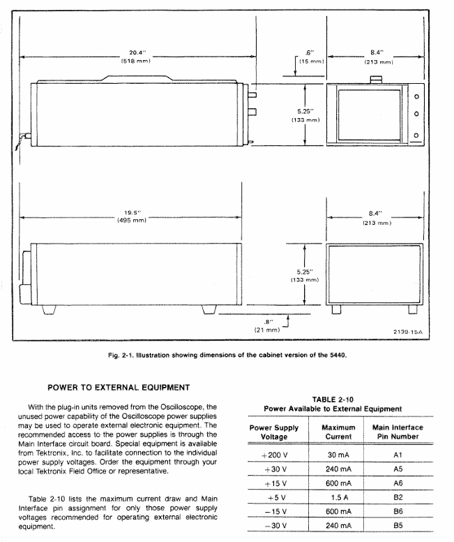
Physical weight 25lbs (11kg)

Panel and shell anodized aluminum panel (gray vinyl coated frame), blue vinyl coated shell

Scale dial 8 × 10 divisions, 1.22cm/division, standard white internal scale line, optional black

Installation and maintenance

(1) Rack installation

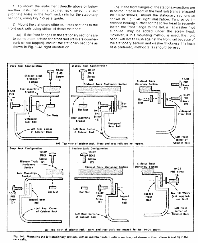
Requirement: Suitable for 19 inch standard racks (Universal, EIA, RETMA, Western Electric hole positions), with a minimum vertical space of 5-1/4 inches and an additional 1/4 inch heat dissipation space above and below; Front rail spacing ≥ 17-5/8 inches (unthreaded) or 17-3/4 inches (tapped); The gap between the rear and the rack enclosure is ≥ 2 inches.

Sliding rail installation: The sliding rail is divided into left and right components (marked LH/RH), with the fixed section installed on the front and rear rails of the rack, the chassis section pre installed with instruments, and the middle section connecting the two; During installation, it is necessary to align horizontally to avoid exchanging left and right (which may cause the safety lock to fail and cause the instrument to slide). The front panel needs to be fixed with 10-32 screws (the rack needs to correspond to the hole position).

Maintenance: The slide rail does not require lubrication, and the dark coating on the sliding parts is permanently lubricated.

(2) Plugin installation and maintenance

Installation: Align the upper and lower slots of the plug-in with the cabin guide rail, and push it into the lock; It can be plugged and unplugged with power, without filling all cabins, only installing the required measuring plugs is needed.

Calibration: After the display unit is calibrated according to the instructions, the vertical/horizontal gain is standardized. The plug-in can be interchanged between cabins without the need for readjustment, but the basic calibration of the plug-in itself needs to be checked to ensure measurement accuracy (refer to the plug-in manual).

(3) Safety regulations

Maintenance safety: Only qualified personnel are allowed to carry out repairs, and individual repairs are prohibited (emergency personnel must be provided); Live maintenance should avoid touching exposed connections/components, and disconnect the power supply before dismantling panels, welding, or replacing components.

Power safety: The power supply must meet the RMS voltage between phase lines and between phase lines and ground ≤ 250V, and the grounding conductor of the power line must be reliably grounded.

Performance check

(1) Testing equipment requirements (key equipment as follows)

Equipment Name Performance Requirements Application Scenarios

DC voltmeter range 0-200V (accuracy 0.1%); 0-3000V (accuracy 1%) low/high voltage power supply inspection and adjustment

Calibration generator amplitude calibration 10mV-1V (accuracy ± 0.25%, 1M Ω load), square wave output gain inspection and adjustment

Timing generator outputs 5ns and 10ns markers (accuracy ± 1%) for scanning timing inspection (5ns, 10ns)

5A48 amplifier plug-in bandwidth DC to 500MHz, display mode CH1 vertical/horizontal system adjustment

5B42 time base plugin scanning speed of at least 10ns/div scanning timing inspection and adjustment

(2) Key inspection items

Trajectory alignment: Horizontal trajectories are aligned with the center horizontal scale line, and vertical trajectories are aligned with the center vertical scale line, with an error of ≤ 0.1 divisions.

Geometric shape: Trajectory curvature/inclination ≤ 0.1 divisions, angle between vertical and horizontal trajectories 90 °± 0.7 °.

Vertical performance:

Gain: Input 1kHz square wave, display 5V reference signal, vertical deflection of 5 divisions ± 0.15 divisions (± 3%).

Bandwidth: Input a 50kHz sine wave, display 6 divisions, increase the frequency until the amplitude drops to 4.2 divisions, and the frequency needs to be ≥ 50MHz (5A48 plugin).

Horizontal performance:

Gain: Input 1kHz square wave, display 5V reference signal, horizontal deviation of 5 divisions ± 0.15 divisions.

Bandwidth: Input a 50kHz sine wave, display 6 divisions, increase the frequency until the amplitude drops to 4.2 divisions, and the frequency needs to be ≥ 2MHz.

Reading system: In dual track mode, readings are displayed at the top/bottom of the CRT without overlap, corresponding to Volts/Div and Sec/Div settings; When CAL controls counterclockwise rotation, the “>” symbol is displayed on the left side of the reading.

TOSHIBA MULTIFUNCTIONAL DIGITAL SYSTEMS

Software License Agreement

Core licensing rules

License Scope: Users are only allowed to use one copy of the software on a single system CPU (device where the software is installed), and can only copy it for usage purposes. The copy must comply with this agreement.

Prohibited behavior: Do not modify, decompile, disassemble or reverse engineer software; Do not sublicense, rent, transfer licenses or software.

Intellectual Property: The software (including fonts and documentation) is proprietary to Toshiba Tec Corporation (TTEC) and its suppliers, protected by copyright laws and international treaties. Users have no intellectual property rights and are licensed as passive code.

Agreement Term and Termination

Effective condition: Installing or using the software is considered acceptance of the terms.

Termination situation: TTEC termination, or user breach (such as violation of prohibited behavior); After termination, all copies of software and documentation must be destroyed; Users can voluntarily terminate (destroy software and copies).

Disclaimer and Limitation of Liability

Disclaimer: The software is provided as is (AS IS) without any express or implied warranties (including merchantability, fitness for a particular purpose, etc.); The cost of repairing/correcting software defects shall be borne by the user.

Limitation of Liability: TTEC and its suppliers shall not be liable for indirect losses (such as loss of profits, data loss), unless personal injury/death is caused by the fault of TTEC or its suppliers.

Government restrictions on rights: The use of technology by the US government must comply with the Technical Data and Computer Software Rights Clause (such as 252.227-7013, 52.227-19), and the contractor is Toshiba Tiger Co., Ltd. from Japan.

Basic information (trademark, copyright, manual system)

Trademark and Copyright

Trademarks: Windows series (Microsoft), Apple series (Apple), PostScript (Adobe), TopAccess (TTEC), etc. are corresponding company trademarks.

Copyright: © 2007 TOSHIBA TEC CORPORATION, Unauthorized reproduction of manuals is prohibited and patent liability is not assumed.

Manual system: Multiple manuals are provided, and users can choose according to their needs, as shown in the following table:

Manual Name Core Content

Quick Start Guide: Device Initial Setup, Accessories (Manual, CD-ROM) Instructions

Operator’s Manual for Basic Functions Basic Functions (with a focus on copying) Usage and Safety Precautions

Functions and settings under the “User Functions” button in the User Functions Guide control panel

Color Guide (color models only) Color related functions (density adjustment, color adjustment, etc.) and basic knowledge of color

TopAccess Guide: This document manages network functions (scanning, job management, etc.) through TopAccess

Network Administration Guide Network Server Setup Guide, Network Troubleshooting (for administrators)

Printing Guide: Windows/Mac/UNIX System Printing Client Software Installation and Printing Operations

Scanning Guide Operation Instructions

The e-Filing Guide uses TWAIN driver, File Downloader, and other operations to perform e-Filing functions

Network Fax Guide network fax function (client sends fax/Internet fax)

User Management Guide: Department Management, User Management Settings, Scan to Email Authentication

TopAccess Overview and End User Mode

1. TopAccess Overview

Definition: A web-based homework and device management tool that supports accessing device information through the network, divided into user mode (regular user) and administrator mode (administrator configuration).

Access prerequisite: The device needs to be connected to the network and configured with TCP/IP settings.

Browser support:

The operating system supports browser versions

Windows Internet Explorer 5.5 SP2+/Firefox 1.5.0.4+(IPv6 requires IE 7.0+)

Macintosh Safari 2.0+/Firefox 1.5.0.4+

UNIX Firefox 1.5.0.4+

Access method: Enter the URL (http://<IP address>or http://<device name>), such as http://10.10.70.105 .

2. Core functions of user mode

(1) View device status (Device Tab Page)

Device information: Display device name, location, model, storage space (such as Save as File space, e-Filing space, fax sending and receiving space), contact information, administrator message, alert (error red/warning yellow).

Option status: Display the installation status of optional units (binders, punching units, fax units, etc.).

Paper status: Display the paper size, type, capacity, and consumption status of each paper box (such as “Near Empty”/”Empty”).

Equipment status indicator light: indicates faults through icons (such as paper jam, paper box open, toner depletion, etc.), which should be resolved by referring to the “Basic Function Operation Manual”.

(2) Managing Jobs

Print homework:

Display: View user submitted print jobs (username, date and time, type, paper size, etc.), refresh the list, and sort by header.

Operation: Delete (select 1 at a time, private print jobs need to be deleted by the administrator), Release (select 1 at a time, private jobs cannot be released).

Fax/Internet fax operation:

Display: View fax transmission jobs (file number, destination, date and time, page number, etc.), which can be refreshed and sorted.

Operation: Delete (select one at a time).

Scan homework:

Display: View scan jobs (target/file name, agent, date and time, page count, status), which can be refreshed and sorted.

Operation: Delete (select one at a time).

(3) Viewing Job Logs

Log type: Each log can store up to 100 entries, displayed in reverse chronological order. If exceeded, the earliest record will be deleted

Print log: username, document name, date and time, type, paper size, page count, number of copies.

Transmission log: serial number, file number, date and time, transmission duration (displayed as “59:59” after 1 hour), page count, destination, department code, mode, status, route.

Receiving logs: serial number, file number, date and time, receiving duration, page count, sender, department code, mode, status, line.

Scan logs: target/file name, username, agent, date and time, page count, mode (6-digit code, including job type/transfer type, etc.), status.

(4) Registering from TopAccess

Template management:

Private template group: up to 200, can set group name, owner, email notification, supports password protection (5 digits); Resetting the group will delete all templates within the group.

Private templates: Up to 60 per group, with the option to select agents (copy/fax/scan, etc., scan up to 2 agents), set parameters such as panel, destination, format, etc., and support password protection.

Public template: Only administrators can create/maintain it, users can view it.

Address book management:

Contact person: manually add/edit/delete (name+email/fax number required), or search and add from LDAP server; Fax parameters can be set (such as ECM, line selection).

Group: Create/edit/delete groups (including multiple contacts) for easy bulk sending.

Email management (requires installation of fax unit):

Type: Confidential email (deleted after a single extraction), Billboard email (multiple extractions), Forwarding email (forwarding to other devices/network folders/email/e-filing).

Operation: Create/edit/delete up to 300 email addresses, set passwords, notifications, storage paths, etc.

(5) View counters (Managing Counters)

Total counter: View the total number of pages copied/printed (small/large paper) and scanned (divided into full-color/two-color/black).

Department counter: After entering the department code, view the counter for a specific department. You can click on the department name to view detailed data.

TopAccess Administrator Mode

1. Overview of Access and Core Functions

Access method: After entering TopAccess, click on “Administration” and enter the administrator password (default “123456”) to log in.

Core functions: settings (devices/networks/printing services, etc.), maintenance (software updates/data backups), registration (public templates/fax forwarding), user and department management, viewing message logs.

2. Key Function Details

(1) Setting up from TopAccess

Device settings: Configure device name, location, administrator password (6-10 alphanumeric characters), energy-saving time (automatic clearing/sleep/shutdown), date and time, TopAccess language, and session timeout (5-999 minutes).

Network settings: Configure TCP/IP (static/dynamic IP), IPv6, IPX/SPX, AppleTalk, LDAP, DNS, SMTP/POP3, FTP, SNMP, SSL certificates, etc.

Copy settings: default color mode, original mode, exposure, maximum number of copies (9/99/999/9999), etc.

Fax settings (requiring installation of fax unit): Terminal ID, fax number, receiving mode, resolution, ECM, etc.

Printing service settings: Enable/disable Raw TCP (port 9100), LPD (port 515), IPP, FTP, NetWare, Email printing, configure port numbers, authentication, etc.

(2) Maintaining from TopAccess

Software management: Upload client software (drivers, PPD files, etc.), delete software (except for Point and Print drivers).

Data backup and recovery: Backup address book/template/email data (generate backup files), restore data from backup files.

Log management: Export logs (CSV format, including print/fax/scan logs), clear logs.

Directory service: Register LDAP servers (up to multiple), configure server IP, ports, and authentication methods.

Device restart: Restart the device (ensuring that no jobs are running).

(3) User and Department Management

Department management:

Function: Register/modify/delete department codes (up to multiple), set department names, output restrictions (full-color/black), clear department counters.

Note: The default ‘Undefined’ department cannot be deleted and is used to count invalid jobs.

User management:

Authentication methods: Supports Windows domain authentication, LDAP authentication, and MFP local authentication (up to 10000 users).

User operation: Create/edit/delete users, set usernames, passwords (local authentication), departments, permission restrictions, reset user counters.

(4) Troubleshooting

Error code: Provide error codes and solutions by job type (print/transmit/scan), for example:

402F: 1200 dpi print job requires additional memory, it is recommended to change to 600 dpi.

0011: Cardboard, the paper needs to be cleared.

1C65: SMTP address not set, administrator needs to configure SMTP server.

Other important notes

Optional component dependencies: Some features require the installation of optional components, such as fax unit for fax function and scanner kit for scanning to email.

Security precautions: Enabling SSL requires importing a certificate (self signed or CA certificate); SMTP/POP3/LDAP authentication requires correct configuration of username and password.

Data limitation: Address book import/export supports CSV format; Up to 100 logs can be stored; Up to 300 email addresses; The maximum number of private template groups is 200.

TOSHIBA e-STUDIO 7516AC Color Multifunctional Printer

Product basic information

Positioning and Model: The Toshiba e-STUDIO 7516AC series is a color multifunctional printer designed for large workgroups, consisting of three models – e-STUDIO 5516AC, e-STUDIO 6516AC, and e-STUDIO 7516AC. Its core goal is to simplify complex office tasks through customized features, balancing efficiency, safety, and environmental requirements.

Core function: Integrated with four basic functions of copying, printing, scanning, and faxing, supporting high-capacity and high-speed document processing, while also having the ability to customize UI and automate workflow, adapting to personalized office scenarios of different enterprises.

Core performance parameters

Specific parameters of performance category (in order of e-studIO5516AC/6516AC/7516AC)

Printing/copying speed color: 55 PPM/65 PPM/75 PPM; Black and White: 65 PPM/75 PPM/85 PPM

First print output time color: 6.4 seconds/6.4 seconds/5.4 seconds; Black and white: 5.2 seconds/4.5 seconds/4.1 seconds

Resolution copying: 600 × 600 dpi; Printing: 600 × 600 dpi (8-bit), 1200 × 1200 dpi (color/2-digit), 3600 × 1200 dpi (black and white/with smoothing, PS3 only)

Maximum monthly copy volume of 480K pages/540K pages/600K pages

Preheating time is about 20 seconds

Scanning speed dual scan document feeder (DSDF): up to 240 IPM for double-sided and up to 120 IPM for single-sided (black and white/color compatible)

Color toner capacity (CMY): 39200 pages (5% coverage); Black (K): 106600 pages (5% coverage)

Power supply and power consumption: 120V, 50/60Hz, 16A; Maximum power consumption: 2.0kW (120V); Super sleep mode: 0.6W

Hardware and operational configuration

Core hardware: Equipped with Intel Atom 1.75GHz dual core processor, 4GB memory and 320GB self encrypting hard drive (SED), the hardware has strong performance and can smoothly run embedded solutions and third-party applications, while ensuring data storage security.

Operation display screen: It adopts a 10.1-inch color WSVGA tiltable touch screen, built-in embedded web browser, and operation logic similar to a tablet; Support customizing the homepage taskbar by department, displaying only high-frequency functions to reduce operational redundancy, and featuring accessible designs such as tilted panels and universal paper tray handles.

Paper processing capability

Capacity configuration: The standard 4-drawer design can accommodate 2280 sheets of paper, while the serial drawer version has a standard capacity of 3520 sheets; The maximum capacity can be expanded to 4780 sheets (4 drawers) or 6020 sheets (series drawers), and the MP2502B 2500 large capacity feeder (only supports LT size) can be optionally selected to reduce frequent paper feeding frequency.

Support range: Paper sizes ranging from 3.9 “x 5.8” to 13 “x 19” regular sizes, 12 “x 47” banners, and envelopes; The paper weight range is 16 pounds Bond to 140 pounds Index (standard drawer), 16 pounds Bond to 110 pounds Cover (bypass feed), suitable for various document printing needs.

Featured features and connectivity

Workflow optimization function

Elevate function: It can customize automated workflows based on enterprise business processes, simplifying multi-step operations (such as scanning, converting formats, uploading to cloud storage) into “one click execution”, reducing manual operations and paper consumption, lowering costs, and improving efficiency.

Print Around: When a printing task is stalled due to paper size, type, or toner issues, other tasks are allowed to print first to avoid printing queue congestion and ensure smooth flow in high load scenarios.

Scan and fax enhancement: supports scan preview (viewing, rotating, and adjusting scanned documents on the touch screen), fax preview (viewing received faxes before deciding whether to print, saving consumables); Scanning can be directly saved in Office formats such as DOCX, XLSX (with embedded OCR enabler).

Connection and compatibility

Mobile and wireless connectivity: Supports AirPrint ® (Apple devices) Mopria ® (Android devices) Wi-Fi Direct, Paired with Toshiba’s exclusive e-BRIDGE Print&Capture application (available for download on iOS/Android), it enables direct printing and scanning of documents on mobile phones/tablets, and sending them back to mobile devices.

Cloud service integration: Through the e-BRIDGE Plus series of applications, it supports OneDrive access ®  for Business、SharePoint ®  Online、Exchange Online、Google Drive ™、 DropBox ®  Wait for cloud storage to print documents, or scan documents and upload them directly to the cloud platform to achieve cross device document sharing.

System and protocol compatibility: compatible with Windows ® (8.1/10/Server 2012 and above) Macintosh ® (macOS X 10.7.4 and above) Unix ®、 Linux ®  System; Support printing protocols such as SMB, LPR/LPD, IPP, Port 9100, etc., to meet different office network environments.

Safety and Environmental Protection Standards

Security protection system

Data Security: Comes standard with a 320GB self encrypting hard drive (SED), supporting automatic data invalidation (ADI) and data overwrite functions to prevent data leakage after the hard drive is stolen or the device is scrapped; Optional FIPS 140-2 certified SED, compliant with government level security encryption standards; Supports IPsec encryption protocols (IKEv1/IKEv2) to ensure secure data transmission between devices and networks.

Access control: Supports multi-dimensional authentication (device authentication, Windows domain authentication, LDAP server authentication, card/NFC authentication), MAC/IP address filtering (10 groups each), role-based access control (RBAC), only authorized users can operate core functions; Simultaneously supporting secure PDF and firmware digital signatures to prevent malicious software attacks and unauthorized firmware tampering.

Compliance certification: Through HCD-PP certification and CC certification (ISO/IEC15408), it complies with internationally recognized information security assessment standards and is suitable for industries sensitive to data security, such as finance and government.

environmental performance

Certification standard: Compliant with ENERGY STAR ®  V3.0 certification, EPEAT Gold registration, using RoHS compliant materials, and using recycled plastic for the body to reduce environmental impact.

Energy saving design: Supports super sleep mode (with a power consumption of only 0.6W), low monthly average energy consumption (TEC value), and reduces operating electricity costs; Equipped with e-Bridge Plus green information function, it can display the company’s environmental contribution data (such as reduced carbon emissions) on the touch screen, guiding employees to use the equipment efficiently.

Optional accessories

Accessory category, model, and function description

GR1330 accessory tray for auxiliary operation accessories, used to place small operating tools or consumables

GR9000 Bluetooth keyboard simplifies device side text input operations

GR1340 10 key numeric keypad improves numerical input efficiency

Binding and output accessories MJ1111B 50 page console stapler, supporting single/multi page stapling binding

MJ1112B 50 page saddle stitch stapler, supporting saddle stitch binding and folding of picture books and manual documents

MJ6106N punching unit (compatible with MJ1111B/MJ112B), supports document punching processing

KA6551 side paper tray provides additional document output channels to avoid confusion with the main tray

Connect and secure accessories GD1370N fax unit/second fax line, expand fax function or add fax line redundancy

GN4020 wireless LAN/Bluetooth module, enabling wireless connection of devices and adaptation to Bluetooth peripherals

GE1230 FIPS 140-2 certified self encrypting hard drive (SED) meets high security level data storage requirements

GP1080 IPsec Security enabler, activates device IPsec encryption function

Function extension accessory GS1080NODE embedded OCR enabler (authorized by seat), supporting the conversion of scanned documents into editable Office formats

GS1090NODE multi workstation printing enabler (authorized by seat), supports users to obtain printing tasks on any device with card authentication

Paper expansion accessory MP2502B 2500 large capacity feeder (only supports LT size), significantly increasing paper reserve capacity

Troubleshooting and Maintenance

Fault code system

Indoor unit fault codes: covering communication faults (such as E03: indoor remote control communication interruption, E04: indoor outdoor communication interruption), sensor faults (such as F01: TCJ sensor open/short circuit, F10: TA sensor fault), hardware faults (such as P10: indoor overflow, P12: DC fan fault), each code corresponds to a clear troubleshooting direction (such as checking line connections, sensor resistance, hardware components).

Outdoor unit fault codes: including communication faults (E06: indoor unit disconnection, E23: outdoor outdoor communication interruption), abnormal pressure/temperature (P03: high exhaust temperature, P20: high pressure protection activated), compressor faults (H01: compressor overcurrent, H02: compressor lock), which need to be checked in conjunction with the 7-segment display on the external unit interface board and manual steps.

Test run operation

Wired remote control (RBC-AMT series): Press and hold the 【 TEST 】 button for more than 4 seconds to enter the test mode, press 【 MODE 】 to switch between ‘cooling/heating’, and the test will automatically exit after 60 minutes. During this period, the temperature cannot be adjusted, and the fault detection will take effect normally.

Wireless remote control: After turning on, wait for 1-5 minutes (5 minutes for the first power on), press [ON/OFF] to start, select “cooling/heating” for [MODE], select “HIGH” for [FAN], activate the test through a specific temperature setting sequence (such as cooling: 62 ° F → 64 ° F → 62 ° F), and the indicator light flashes for 10 seconds before starting.

Regular maintenance checklist

Daily maintenance: Clean the filter screen weekly (standard filter screen can be washed with water), check the paper capacity indicator, check the remaining consumables (toner, toner cartridge) monthly, and confirm that the safety lock and certification functions are normal.

Quarterly maintenance: Clean the scanning platform and feeder rollers, check network connection stability, test IPsec and data encryption functions; Every year, professionals inspect the health of SED hard drives, calibrate sensors (TA/TC1/TC2), and check the operating status of environmental protection modes.

TOSHIBA e-STUDIO 7516AC Series Color Multifunctional Printer

Product basic information

Product Series and Positioning: The Toshiba e-STUDIO 7516AC series is a color multifunctional printer designed specifically for large workgroups. It includes three models: e-STUDIO 5516AC, e-STUDIO 6516AC, and e-STUDIO 7516AC. The core goal is to simplify office processes, improve efficiency, and balance safety and environmental protection through advanced features.

Core function coverage: integrating four major functions of copying, printing, scanning, and faxing, supporting diverse document processing needs, and possessing the ability to customize UI and automate workflow, adapting to personalized office scenarios of different enterprises.

Core Performance Parameters (Table Display)

Specific parameters of performance category (in order of e-studIO5516AC/6516AC/7516AC)

Printing/copying speed color: 55 PPM/65 PPM/75 PPM; Black and White: 65 PPM/75 PPM/85 PPM

First print output time color: 6.4 seconds/6.4 seconds/5.4 seconds; Black and white: 5.2 seconds/4.5 seconds/4.1 seconds

Resolution copying: 600 × 600 dpi; Printing: 600 × 600 dpi (8-bit), 1200 × 1200 dpi (color/2-digit), 3600 × 1200 dpi (black and white/with smoothing, PS3 only)

Maximum monthly copy volume of 480K pages/540K pages/600K pages

Preheating time is about 20 seconds

Scanning speed dual scan document feeder (DSDF): up to 240 IPM for double-sided and up to 120 IPM for single-sided (black and white/color compatible)

Color toner capacity (CMY): 39200 pages (5% coverage); Black (K): 106600 pages (5% coverage)

Hardware and operational configuration

Core hardware: Equipped with Intel Atom 1.75GHz dual core processor, 4GB memory and 320GB self encrypting hard drive (SED), providing hardware foundation for high-speed processing and data security; Support external device expansion such as Bluetooth keyboard and wireless LAN to enhance operational flexibility.

Display screen and operation: Equipped with a 10.1-inch color WSVGA tiltable touch screen, built-in embedded web browser, operation logic similar to a tablet, supports custom homepage taskbar, only displays high-frequency usage functions, reduces operation clutter; Simultaneously supporting accessible designs such as tilted panels and universal paper tray handles.

Paper processing capability

Capacity configuration: The standard 4-drawer design can accommodate 2280 sheets of paper, while the serial drawer version has a standard capacity of 3520 sheets; The maximum capacity can be expanded to 4780 sheets (4 drawers) or 6020 sheets (series drawers), and the MP2502B 2500 large capacity feeder can be optionally selected to further enhance paper storage.

Supports sizes and types: can handle regular paper from 3.9 “× 5.8” to 13 “× 19”, banners from 12 “× 47”, and envelopes; The paper weight range is 16 pounds Bond to 140 pounds Index (standard drawer), 16 pounds Bond to 110 pounds Cover (bypass feed), suitable for various document printing needs.

Featured features and connectivity

Workflow optimization function

Elevate function: It can customize automated workflows based on enterprise business processes, simplify multi-step operations into “one click execution”, reduce manual operations and paper consumption, lower costs, and improve efficiency.

Print Around: When a printing task is stalled due to paper size, type, or toner issues, allow other tasks to print first to avoid clogging the print queue.

Scan and fax enhancement: Supports scan preview (viewing, rotating, adjusting scanned documents on the touch screen), fax preview (viewing received faxes before deciding whether to print, saving consumables), and scans can be directly saved in Office formats such as DOCX, XLSX (with embedded OCR enabler).

Connection and compatibility

Mobile and wireless connectivity: Supports AirPrint ® (Apple devices) Mopria ® (Android devices) Wi-Fi Direct, Paired with the e-BRIDGE Print&Capture application, it enables direct printing and scanning of documents from mobile phones/tablets to be sent back to mobile devices.

Cloud service integration: Through the e-BRIDGE Plus series of applications, it supports OneDrive access ®  for Business、SharePoint ®  Online、Exchange Online、Google Drive ™、 DropBox ®  Wait for cloud storage to print documents, or scan documents and upload them directly to the cloud platform.

System and protocol compatibility: compatible with Windows ® (8.1/10/Server 2012 and above) Macintosh ® (macOS X 10.7.4 and above) Unix ®、 Linux ®  System; Support printing protocols such as SMB, LPR/LPD, IPP, Port 9100, etc., to meet different office network environments.

Safety and Environmental Protection Standards

Security protection system

Data Security: 320GB SED supports automatic data invalidation (ADI) and data overwrite to prevent hard disk data leakage; Optional FIPS 140-2 certified SED, compliant with government level security requirements; Support IPsec encryption to ensure secure data transmission between devices and networks.

Access control: supports user authentication (device side/Windows domain/LDAP server), MAC/IP address filtering (10 groups each), role-based access control (RBAC), secure PDF, firmware digital signature, to prevent unauthorized operations and malicious attacks.

Compliance certification: Through HCD-PP certification and CC certification (ISO/IEC15408), it meets strict security compliance requirements and is suitable for industries sensitive to data security, such as finance and government.

environmental performance

Certification standard: Compliant with ENERGY STAR ®  V3.0 certification, EPEAT Gold registration, use RoHS compliant materials, use recycled plastics to reduce environmental impact.

Energy saving design: Supports super sleep mode (with a power consumption of only 0.6W), low monthly average energy consumption (TEC value), and reduces operating costs; The green information function of e-BRIDGE Plus can display environmental contribution data on the touch screen, guiding efficient use.

Optional accessories (table display)

Accessory category, model, and function

Auxiliary operation accessories GR1330 (accessory tray), GR9000 (Bluetooth keyboard), GR1340 (10 key numeric keypad)

Binding and output accessories MJ1111B (50 page console stapler), MJ1112B (50 page saddle stitch stapler), MJ6106N (punching unit), KA6551 (side paper tray)

Connection and security accessories GD1370N (fax unit/second fax line), GN4020 (wireless LAN/Bluetooth module), GE1230 (FIPS 140-2 SED), GP1080 (IPsec enabler)

Function extension accessories GS1080NODE (embedded OCR enabler, authorized by seat), GS1090NODE (multi workstation printing enabler, authorized by seat) GB2300NODE(e-BRIDGE Plus for Business V3.0)

Paper expansion accessory MP2502B (2500 large capacity feeder, only supports LT size)

Key issues

Question 1: What are the core advantages of Toshiba e-STUDIO 7516AC series in high load office scenarios? What are the corresponding key parameter supports?

Answer: The core advantages are high speed, high capacity, and high stability, which can meet the high-frequency and large-scale document processing needs of large workgroups. The specific parameter support is as follows:

Speed support: Color printing/copying speed up to 75 PPM, black and white up to 85 PPM, first print output time as short as 4.1 seconds (black and white) and 5.4 seconds (color), preheating time of about 20 seconds, reducing waiting time;

Capacity support: The maximum monthly copying capacity is up to 600K pages, with a standard paper capacity of up to 3520 sheets (series drawer), and can be expanded to 6020 sheets+2500 sheets (optional feeder), reducing frequent paper additions;

Stability support: Equipped with Intel Atom dual core processor, 4GB memory, and 320GB self encrypting hard drive, the hardware configuration is strong, and it also supports Print Around function to avoid printing queue congestion and ensure smooth operation under high loads.

Question 2: How does this series of printers ensure the security of sensitive documents for enterprises? What levels of security measures are covered?

Answer: To ensure the security of sensitive documents through four levels of data storage security, transmission security, access control, and compliance authentication, specific measures are as follows:

Data storage security: Equipped with a 320GB self encrypting hard drive (SED), supporting automatic data invalidation (ADI) and data overwrite functions to prevent data leakage after the hard drive is stolen or the device is scrapped; Optional FIPS 140-2 certified SED, meeting government level encryption standards;

Data transmission security: Supports IPsec encryption protocols (IKEv1/IKEv2) to ensure the security of data transmission between devices and networks, avoiding interception or tampering during the transmission process;

Access control security: supports multi-dimensional authentication (device authentication, Windows domain authentication, LDAP server authentication), MAC/IP address filtering (10 groups each), role-based access control (RBAC), only authorized users can operate copy/print/scan/fax functions; Simultaneously supporting secure PDF and firmware digital signatures to prevent malicious software attacks;

Compliance certification and security: Through HCD-PP certification and CC certification (ISO/IEC15408), it complies with internationally recognized information security assessment standards to ensure the compliance and reliability of security measures.

Question 3: From the perspective of environmental protection and cost control, what are the design highlights of this series of printers? What practical benefits can it bring to the enterprise?

Answer: The highlights of environmental protection and cost control design are concentrated in three aspects: energy conservation and consumption reduction, consumables optimization, and process paper reduction. The actual benefits are as follows:

Energy saving and consumption reducing highlights: compliant with ENERGY STAR standards ®  V3.0 certification and EPEAT Gold registration, supporting super sleep mode (power consumption of only 0.6W), with low monthly average energy consumption (TEC value); Actual benefits: Reduce electricity expenses while lowering the company’s carbon footprint, in line with green office policies;

Highlights of consumables optimization: Large toner capacity (color 39200 pages/black 106600 pages, 5% coverage), reducing toner replacement frequency; Support fax preview (view before printing), scanning and electronicization (save directly to Office format); Actual benefits: Reduce the procurement cost of consumables such as carbon powder and paper, and decrease the labor cost of replacing consumables;

Highlights of process paper reduction: Elevate function simplifies multi-step processes into one click automated operations, reducing manual paper processes; Support cloud scanning/printing to reduce the circulation of paper documents; Actual benefits: Reduce paper consumption while improving work efficiency, indirectly reducing the time and storage costs associated with managing paper documents.

TOSHIBA CANVIO BASICS portable hard drive

Product Overview

1.1 Basic Information

Product Name: TOSHIBA CANVIO BASICS Mobile Hard Drive

Packaging components: Consists of three types of fixed items, as shown in the table below:

Component name, quantity, and purpose

CANVIO BASICS hard disk body 1 core storage carrier

One USB 3.0 Micro-B cable connects the hard drive to the computer, transferring data and providing power

1 set of supporting documents (including security guidelines) including multilingual operation instructions, security specifications, and compliance statements

Language version: covering more than 20 languages, including English (EN), German (DE), French (FR), Italian (IT), Spanish (ES), Turkish (TR), Russian (RU), Ukrainian (UK), etc., to meet the needs of users in different regions.

Interface specifications: Adopting USB 3.2 Gen 1 interface (compatible with USB 3.0/2.0), with Micro-B connector on the hard drive end and Type-A connector on the computer end.

System requirements

2.1 Operating System Adaptation

Windows system:

Supported versions: Windows 10, Windows 8.1;

Format requirement: Pre installed with NTFS file system, can be used directly without additional formatting.

MacOS system:

Supported versions: macOS v10.15 (Catalina), v10.14 (Mojave), v10.13 (High Sierra);

Format requirement: Must be reformatted (default format incompatible), it is recommended to format to APFS or Mac OS Extended format supported by macOS.

2.2 Hardware and Power Requirements

Port requirements: The computer requires one free USB 3.0 or USB 2.0 port (USB 3.0 is backward compatible with USB 2.0, and if a USB 2.0 port is used, the transfer speed will be reduced to USB 2.0 level);

Power supply method: Bus powered, no external power supply required, all current is provided through USB port;

Disabled devices: Cannot connect passive USB hubs (without independent power supply), keyboard/mouse and other USB device expansion interfaces, which may result in insufficient power supply or data transmission errors.

Operation process

3.1 Connection steps

Hard drive connection: Insert the USB 3.2 Gen 1 Micro-B connector into the corresponding port of the hard drive (note polarity, do not forcefully plug or unplug);

Computer connection: After the computer is fully powered on and the operating system is loaded, insert the USB Type-A connector into the USB Type-A port of the computer;

Status confirmation:

Windows: The Power/Data indicator light is on, the hard drive is automatically mounted, and a new hard drive icon is displayed in “My Computer”;

Mac: The Power/Data indicator light is on, the hard drive is ready directly, and the desktop displays the hard drive icon.

3.2 Secure uninstallation

It is strictly prohibited to directly unplug the cable (which may cause data loss or physical damage to the hard drive), and it should be operated according to the system type:

System type uninstallation steps

Windows 1. Click on the “Hardware and Pop Up Media” icon on the taskbar;

2. Select TOSHIBA hard drive from the pop-up list;

3. After receiving the “Safely Removable” notification, click “OK” and unplug the cable

Mac 1. Ctrl click on the desktop hard drive icon and select “Eject”;

2. Alternatively, simply drag the hard drive icon to the trash can;

3. After the icon disappears, unplug the cable

3.3 Cleaning and Maintenance

Cleaning prerequisite: The hard drive must be physically disconnected from the computer first (unplug the USB cable);

Cleaning supplies: Use standard cleaning agents (such as neutral cleaning agents), and prohibit the use of corrosive liquids (such as phenol, gasoline, diluents, etc.);

Operation requirements: After cleaning, wipe off any residual liquid on the surface to prevent liquid from seeping into the interior of the hard drive and causing a short circuit.

Frequently Asked Questions (FAQ) and Troubleshooting

4.1 Frequently Asked Questions and Answers

Problem Description Answer

Does Windows require an additional USB driver? No need, the driver is integrated into the Windows system and plug and play

2. Can the computer system be started from this hard drive? No, Windows does not support booting the system from an external hard drive

Why does a hard drive not require a fan? Adopting optimized heat dissipation structure, it can naturally dissipate heat and achieve near silent operation (without fan noise)

Why does Windows display a smaller capacity than indicated? Differences in calculation methods: Manufacturers use decimal (1TB=1000GB), systems use binary (1GB=1024MB), and 1TB hard drives display approximately 931GB

Can I copy the operating system to another computer? No, you need to reinstall according to the installation guide provided by the operating system manufacturer. Simple copying cannot achieve system operation

4.2 Fault Handling Plan

Fault 1: The computer does not recognize the hard drive at all

Troubleshooting steps: ① Check if the USB cable connection is secure; ② If using a USB hub, confirm that the hub has independent power supply; ③ If using an expansion card, check if the expansion card is working properly and update the firmware.

Fault 2: The hard drive displays’ unable to start device ‘

Possible reasons: ① Insufficient power supply (check if the USB port is in good contact); ② Hard disk hardware malfunction (requires contact with after-sales maintenance).

Fault 3: The hard drive is not displayed in “My Computer”, but it exists in the Device Manager

Solution steps:

Right click on “My Computer” and select “Manage”;

Enter ‘Disk Management’ and confirm that the hard drive is in the list;

Right click on the hard disk partition and select “Delete Partition” (note: data may be lost);

Right click on unallocated space and select ‘New Primary Partition’, then follow the wizard to complete the setup;

Confirm formatting (recommended NTFS format), and once completed, it can be displayed.

Fault 4: When formatting, it prompts’ unable to complete formatting ‘

Reason: Mostly caused by the use of FAT file system (insufficient compatibility);

Solution: Replace with NTFS file system and reformat.

Compliance and environmental requirements

5.1 Certification Compliance

CE certification: The product complies with relevant EU directives (such as the EMC electromagnetic compatibility directive), and the responsible party is Toshiba Electronics Europe GmbH (Dusseldorf, Germany);

UKCA certification: compliant with British standards, responsible by Toshiba Electronics Europe GmbH UK branch (Surrey, UK);

REACH compliance: Toshiba will provide users with relevant information on chemical substances in its products to comply with the EU’s Chemical Registration, Evaluation, Authorization and Restriction Regulations.

5.2 Environmental Protection Disposal

Disposal requirements: The product must bear the label “Prohibited from being disposed of as household waste” and must be handled by a professional industrial waste organization (such as a qualified recycler);

Special regional requirements: Türkiye market shall comply with AEEE regulations (electronic waste recycling regulations);

Risk Warning: Self disassembly may cause capacitor explosion or release of toxic gases, violating the Waste Disposal and Cleaning Law.

TOSHIBA TOSBERT TM VF-nC1 Industrial Inverter

Product Overview

1.1 Basic Information

Model: TOSBERT TM VF-nC1 Industrial Inverter

Applicable motor: only for three-phase induction motors, cannot drive single-phase motors

Power and voltage specifications: covering three voltage levels, with specific parameters as shown in the table below:

Voltage level, power range (kW), model example, output current (A), suitable motor capacity (kW)

Single phase 100V level 0.1-0.75 VFNC1S-1001P 0.7-4.0 0.1-0.75

Single phase 200V level 0.2-2.2 VFNC1S-2002P 1.4-10.0 0.2-2.2

Three phase 200V level 0.1-2.2 VFNC1-2001P 0.7-10.0 0.1-2.2

Single phase 200V level (with filter) 0.2-2.2 VFNC1S-2002PL 1.2-10.7 0.2-2.2

Core control method: Adopting sine wave PWM control, the output frequency range is 0.5-200Hz (default 0.5-80Hz), and the voltage/frequency characteristics can be adjusted through parameters (V/f constant, sensorless vector control).

Safety regulations

2.1 Warning System

The manual divides safety warnings into two levels, clarifying the consequences of risks and operational requirements:

Typical scenario examples of warning type meanings

Warning: Incorrect operation may result in death or serious injury. Disassembling the front cover while live, connecting input power to output terminals, and operating without grounding

Incorrect handling of the solution may result in minor injuries or property damage. Touching the heat sink, using incompatible chemicals, and installing in a vibrating environment

2.2 Mandatory Safety Requirements

Grounding: D-type grounding (formerly Class 3 grounding) must be used, and the grounding wire diameter should be ≥ 3.5mm ² (refer to the terminal specification table for details) to ensure safe conduction of leakage current in case of fault.

Power off waiting: After disconnecting the input power, wait for at least 15 minutes to confirm that the charge light is off and the DC main circuit voltage is ≤ 45V before touching the terminal.

Installation base: It needs to be fixed on a metal base that can withstand the weight of the equipment to prevent it from falling; Choose NEMA 3R protection model (such as 5000 series) for outdoor/harsh environments.

Emergency stop: It must be equipped with an emergency stop device independent of the frequency converter (such as mechanical braking), and the frequency converter alone cannot achieve immediate shutdown.

Parameter settings

3.1 Parameter Classification and Core Parameters

Parameters are divided into three categories: basic parameters, extended parameters, and special parameters. The core parameters and functions are as follows:

Parameter Category Parameter Code Function Description Adjustment Range Default Values Key Role

Basic parameter CMod instruction mode selection (source of run/stop instructions) 0- Terminal board/1- Panel 1 Determine control mode

FMod frequency setting mode selection: 0- Terminal board/1- Panel, etc. 2. Determine the frequency adjustment method

ACC/DEC acceleration time 1/deceleration time 1 0.1-3000 seconds 10.0s to prevent current overload during startup/shutdown

FH/UL maximum frequency/upper limit frequency 30-200Hz/0.5-FH 80Hz/80Hz limits the maximum operating frequency of the motor

Extended parameter F300 PWM carrier frequency 2/4/8/12/16kHz 12kHz balanced motor noise and inverter losses

F250-252 DC braking parameters (starting frequency/current/time) 0.0-FHHz/0-100/0-20s 0.0Hz/50%/1.0s to achieve rapid shutdown

OLn electronic thermal protection characteristics 0-7 (corresponding to different protections) 0 adaptation standard motor/VF motor protection

Special parameter RUL wizard function (quick setting) 0-5 (5-class wizard) 0 Simplified parameter configuration (such as basic settings)

RUH History Record Function – Display the Last 5 Modified Parameters

3.2 Parameter Setting Process

Enter setting mode: Press the MON key to switch to “parameter setting mode” (display “RUH”);

Parameter selection: Use the △/▽ keys to select the target parameter (such as CMod);

Modify parameters: Press the ENT key to enter editing, and then use the △/▽ keys to adjust the values;

Save parameters: Press the ENT key again, and the parameters and values will alternate to indicate successful saving;

Reset default: Set the basic parameter “Eyp” to 3 to restore all parameters to their factory default values (with the need to shut down first).

Installation and wiring

4.1 Installation environment requirements

Temperature: Operating environment temperature * * -10 ℃ -50 ℃ * *. When the ambient temperature is greater than 40 ℃, the warning label on the top of the equipment should be removed and the rated output current should be reduced (such as the current of the 2007P model dropping from 4A to 3.6A at 40-50 ℃);

Humidity: Relative humidity of 20% -93%, no condensation;

Vibration: Vibration acceleration<5.9m/s ² (10-55Hz), avoid installing near strong vibration equipment such as machine tools;

Other: No dust, corrosive gases, oil mist, keep away from heat sources (such as transformers, heaters).

4.2 Terminal Wiring Specification

Main circuit terminals:

Screw specifications: M3 (low power)/M3.5 (high power), tightening torque of 0.8N · m/1.0N · m respectively;

Wiring requirements: Connect the input (R/L1, S/L2, T/L3) to the power supply, and the output (U/T1, V/T2, W/T3) to the motor. Reverse connection is prohibited as it may damage the inverter;

Grounding terminal: It needs to be independently grounded with a wire diameter of ≥ 3.5mm ² (refer to section 10.1 wiring table).

Control circuit terminals:

Screw specifications: M2/M3, wire diameter 0.3-1.5mm ², sheath stripping length 5-6mm;

Wiring taboos: Control circuit and main circuit wiring should be separated (not parallel, not bundled, different conduit) to avoid interference.

4.3 Wiring precautions

It is prohibited to connect capacitive devices (such as noise filters and surge absorbers) on the output side, as this may cause a fire;

The length of the main circuit line is ≤ 30m, and if it exceeds this limit, the wire diameter needs to be increased (for example, for a 200V level 0.75kW motor, a wire length>30m requires a wire of ≥ 2.5mm ²);

When multiple inverters share a power supply, each one needs to be equipped with an independent MCCB (circuit breaker) to avoid the spread of faults.

Operation and monitoring

5.1 Operating Mode

Panel control: Set CMod=1, start with RUN key, stop with STOP key, adjust frequency with △/▽ key;

Terminal control: Set CMod to 0 and control operation by short circuiting the F-CC (forward rotation) and R-CC (reverse rotation) terminals;

Jog operation (JOG): Set the input terminal function to “JOG”, the motor runs at a fixed frequency of 5Hz when short circuited, and stops freely after disconnection;

Preset speed operation: By allocating SS1-SS4 terminals (a total of 4 terminals), 15 levels of preset speed can be achieved (F287-F294 parameters need to be set).

5.2 Status Monitoring

Monitoring content: The output frequency, load current (%/A), input voltage (DC), output voltage (%/V), cumulative running time (0.01=1 hour), etc. can be viewed through the “status monitoring mode” (press MON button twice);

Fault display: When tripped, the LED displays a fault code (such as “OC1” indicating acceleration overcurrent), and the FL relay operates (fault output);

Alarm message: Non trip warning (such as “rEr” indicating retry), only prompts not to stop the machine, and attention should be paid to the equipment status.

Fault handling

6.1 Common tripping faults and remedies

Fault code, fault type, possible cause, remedial measures

OC1 acceleration overcurrent acceleration time is too short, motor impedance is too small, extending ACC time (such as changing from 10s to 20s), checking motor insulation

OP2 deceleration overvoltage deceleration time too short, excessive regenerative energy prolongs dEC time, F305 is enabled (overvoltage limited operation)

OH inverter overheating fan fault, poor ventilation, environment overheating. Replace the fan, clean the ventilation opening, and improve environmental heat dissipation

OL2 motor overload, excessive load, long low-speed operation time to reduce load, adjust electronic thermal protection level (OLn=4 compatible with VF motor)

6.2 Fault reset method

Panel reset: In the shutdown state, press the STOP button to display “LLr”, then press the STOP button to reset (the fault needs to be eliminated first);

External reset: Short circuit the control terminal RST to CC and disconnect it (RST function needs to be assigned first);

Power off reset: Disconnect the input power supply, wait for 15 minutes, and then power it back on (used in emergency situations, not recommended for frequent operation).

Maintenance and Quality Assurance

7.1 Regular Maintenance Plan

Maintenance Type Cycle Maintenance Content Precautions

Daily inspection of environmental temperature, vibration and noise, load current, and alarm light status without stopping the machine. Visual and instrument checks are required

During the 3-6 month maintenance cycle, terminal tightening, dust removal (ventilation/circuit board), and capacitor inspection must be carried out by cutting off the power for 15 minutes and confirming that the voltage is ≤ 45V before operation

Long term storage: Power on for more than 5 hours every 2 years (motor disconnected), gradually increase the voltage with a transformer to restore capacitor performance, and avoid direct commercial power supply

7.2 Service life and replacement of vulnerable parts

Cooling fan: With a lifespan of approximately 30000 hours (2-3 years of continuous operation), it should be replaced in case of abnormal noise or stoppage;

Electrolytic capacitor: The lifespan of the smoothing capacitor in the main circuit is about 5 years (normal environment). Check for no leakage and ensure that the safety valve is not protruding. Otherwise, replace it;

Fuse: with a lifespan of about 10 years, regularly inspect the appearance, and replace it with the same specification (such as CC/J grade 8A) after melting.

7.3 Warranty Scope

Warranty period: 12 months from the delivery date, only covering the frequency converter host;

Free repair: Parts malfunctions that occur under normal use (such as fans and capacitors);

Disclaimer:

Improper use (such as overload, misconnected power supply);

Self modification/repair;

Natural disasters (fire, earthquake) or abnormal voltage;

Out of range applications (such as driving single-phase motors).

Compliance and Disposal

8.1 Certification Compliance Requirements

CE certification:

EMI filters need to be installed on the input side (such as EMFA2006Z suitable for 200V low power);

Shielded wires are used for the main circuit/control circuit, and the shielding layer is grounded (with a distance of less than 10cm from the inverter);

UL/CSA certification:

Use copper wires above 75 ℃, equipped with CC/J level fuses (such as 4A fuses for the 2002P model);

Branch circuit protection must comply with local electrical regulations (such as NEC in the United States and CEC in Canada).

8.2 Equipment disposal

Mandatory requirement: Waste frequency converters must be disposed of by professional industrial waste disposal institutions (self disassembly is prohibited);

Risk Warning: Self disposal may lead to capacitor explosion and release of toxic gases, violating the Waste Disposal and Cleaning Law;

Contact organization: You can contact Toshiba’s regional branches at the end of the manual to obtain compliance disposal channels.

TOSHIBA TE2 series low-voltage digital solid-state soft starter

Equipment specifications and core functions

1. Basic electrical specifications

Input voltage 208-600VAC (± 10%), 50/60Hz three-phase AC (18-48A model optional single-phase)

Output current of 18-1250A (continuous rated) is distinguished by model, for example, TE2-18-BP is 9-18A, TE2-1250-BP is 625-1250A

Starting capacity 500% rated current, 20 seconds (standard duty); 60 second (heavy duty) SCR endurance capability

Control power supply 120VAC (standard), 240VAC (optional) to be provided by the customer, VA requirements according to model: 100VA for 18-48A, 1000VA for 1250A

Protection level: Open type (to be installed inside NEMA 1/12 enclosure), anti dust/splash requires additional enclosure

Communication interface RS485 Modbus RTU baud rate 9600/19200/38400bps, address 1-247

2. Core functions and protective features

Start mode voltage ramp (VR) F010=1/3, initial voltage 0-100% (F011/F015), ramp time 1-120 seconds (F013/F017)

Current ramp (CR) F010=2/4, initial current 0-600% FLA (F012/F016), current limit 200-600% FLA (F014/F018)

Dual slope switching external contact point control (TB1-6/7), supporting VR+VR, CR+CR, VR+CR, CR+VR combination

Jog voltage 5-100% (F019), time 1-20 seconds (F020), or current 100-500% FLA (F021)

Kick Start voltage 10-100% (F022), time 0.1-2 seconds (F023), used to break through high static friction loads

Protection function: Thermal overload protection NEMA Class 5-30 (when F003 is started and F004 is running), supports manual/automatic reset (F005)

Phase protection phase loss (current<12% CT value), phase imbalance (5-30%, F040), phase rotation (ABC/ACB, F098)

Voltage protection overvoltage 1-10% (F032), undervoltage 1-20% (F034 startup/F036 operation), voltage imbalance 1-30% (F030)

Current protection overcurrent 100-300% FLA (F042), undercurrent 10-90% FLA (F044, load loss detection), grounding fault 5-90% CT value (F046)

Mechanical protection start interval lock (1-60 minutes, F050), hourly start limit (1-10 times, F049), reverse lock (1-60 minutes, F048)

Installation and wiring

1. Installation requirements

Environmental temperature conditions: 0-40 ° C (working), -5-40 ° C (storage); Humidity: 5-95% RH (no condensation) Avoid dust, corrosive gases, and vibration (<0.5G)

The installation spacing should be ≥ 25mm (1 inch) on both sides and ≥ 100mm (4 inches) on both sides to ensure heat dissipation. Multiple units should be placed side by side with gaps left

Cooling direction: The ribs of the cooling fins are vertically installed to assist with fan cooling, ensuring smooth airflow

The shell requirement is that open models should be installed in NEMA 1 (indoor) or NEMA 12 (dustproof and splash proof). The size of the inner and outer shells of the shell should meet the requirements of heat dissipation: for example, the shell volume of 18-481 should be ≥ 0.05m ³

2. Wiring configuration (key terminals)

(1) Power wiring (main circuit)

L1/L2/L3 (R/S/T) main power input three-phase 208-600VAC, requires circuit breaker/isolation switch TE2-18-BP: 10AWG, torque 35in lbs (M5 bolt)

T1/T2/T3 (U/V/W) motor output is connected to a three-phase motor, and reverse input/output TE2-1250-BP: 4 × 500kCMIL, torque TBD is strictly prohibited

The grounding terminal equipment shall be grounded according to NEC specifications, with a wire diameter not less than 1/2 of the phase wire. For example, a 10AWG phase wire shall be paired with an 8AWG grounding wire

(2) Control wiring (TB1 DC 24V, TB2 AC 120/240V)

TB1 (DC 24V) 1-3 3-wire control (Start/Stop) 1 connected to Start (NO), 2 connected to the common terminal, 3 connected to Stop (NC)

External interlock (NC) 4-5 connected to low oil level/high temperature switch, factory jumper needs to be removed

6-7 dual slope switch to external contacts, close and activate slope 2

7-8 Jog: Connect to external contacts, close to activate Jog (requires Start command)

9-10 analog output (4-20mA) connected to PLC/instrument, monitoring current/voltage/thermal capacity (F108 setting)

11-12 fault output (optocoupler Triac) connected to PLC, conducting in case of fault (240VAC/50mA max)

TB2 (AC control power supply) 21-22 (A1-A2) control power supply input 120VAC (standard), requires 1A fuse connection

13-20 auxiliary relay outputs 3 relays: 2 SPDT (13-18), 1 SPST (19-20), 240VAC/5A

Parameter programming

1. Core mandatory parameters

The rated current (FLA) of F001 motor must be set to the FLA on the motor nameplate, otherwise the soft starter will not operate. Range: 50-100%. The maximum current of the soft starter is 9-18A, such as TE2-18-BP

The service factor (SF) of F002 motor is set according to the motor nameplate, affecting the FLA upper limit 1.0 range of 1.00-1.30. If SF ↑, F001 can be set within the range ↓

F003/F004 Start/Run Overload Level NEMA Class 5-30, Match Motor Overload Capacity 10 (Class 10) Set High Level (e.g. Class 20) during Start to Avoid False Alarm

F010 Slope Type Selection: Choose Voltage/Current Slope and Double Slope Combination 1 (VR1+VR2). For heavy loads, choose CR, and for light loads, choose VR

F014/F018 maximum current limit limits the starting current and protects the power grid and motor by 350%. When the FLA power grid capacity is small, set it low (such as 250%), and when overloaded, set it high (such as 500%)

2. Programming operation process

Enter programming mode: In the status display mode (default display of A-phase current), press the 【 Fn 】 key to enter the F001 parameter interface.

Adjust parameters:

Press the ←/→ key to select the digit to be modified (flashing);

Press the 【 ↑/↓ 】 keys to adjust the value (long press for 2 seconds to start automatic stepping);

Press the 【 ENT 】 key to save and display ‘End’ for confirmation.

Password protection:

Set F070 to a non-zero value (1-999) to enable the password, and enter the password for the next modification;

If you forget your password, please contact Toshiba customer service to restore the factory settings (F071=2) without clearing the password.

Communication programming: Connect PLC/upper computer through RS485 Modbus and modify parameter registers (such as register address 0x0001 corresponding to F001).

Startup and troubleshooting

1. Initiation process and inspection

Step operation content Key checkpoints

1. Confirm that the wiring of the main power supply, motor, and control power supply is correct, the grounding is reliable, and there is no looseness

The required parameters F001 (FLA), F002 (SF), and F010 (slope type) for parameter settings have been correctly configured

3. Power on test: Connect the control power supply, the “Power On” LED lights up and displays 【 0000. 】 (phase A has no current)

Press the Start button to start the test, the motor accelerates according to the set slope, the “At Speed” LED lights up (the motor reaches full speed), and the bypass contactor is closed

5. If the machine stops during startup, check the fault code (such as “oLA”=overload, increase F003)

2. Common faults and troubleshooting

Troubleshooting steps for fault codes and causes

NFLA motor FLA not set (F001=0) 1. Enter programming mode; 2. Let F001 be the motor nameplate FLA; 3. Restart after saving

1. Check if the main power supply L1/L2/L3 is out of phase during PLc operation; 2. Check if the motor wiring T1/T2/T3 is loose; 3. Confirm that the phase loss protection (F101) has not been mistakenly enabled

Overload during oLA startup: 1. Check if F003 (startup overload level) is too small (if set to Class 5), it can be increased to Class 15; 2. Check if the load is too heavy, reduce the starting load or increase the current limit (F014)

SSd SCR short circuit or no load 1. Disconnect the power supply and measure whether the SCR (L1-T1, L2-T2, L3-T3) is short circuited; 2. Confirm that the motor is connected (no load will report this fault)

Ground fault during GFc operation: 1. Check if the motor winding is grounded; 2. Check if the cable insulation is damaged; 3. Adjust the grounding fault threshold (F046) or delay (F047)

3. Fault recording and reset

Fault record: F085-F093 stores the last 3 faults, including fault codes (F085/F088/F091), timestamps (F086/F089/F092), and date stamps (F087/F090/F093).

Reset method:

Manual reset: After troubleshooting, press the [Reset] button. If there is an overload fault, wait for the motor to cool down (heat capacity H ≥ F059);

Automatic reset: F052 selects the fault type (such as 4=phase loss), F053 sets the reset frequency (1-10 times), 1 minute/time;

Remote reset: Disconnect the control power and reconnect it (applicable to scenarios without Reset button).

Maintenance and Appendix

1. Regular maintenance

Maintenance project cycle operation requirements

Clean the heat sink every 3 months (in dusty environments) and blow it with 80-100psi dry compressed air. Do not use chemicals/metal brushes

Check the power/control terminals for looseness every 6 months and tighten them again (according to torque requirements)

Fan inspection: Every year, listen to the running noise of the fan. If there is any abnormality, replace it (with a lifespan of 3 years/30000 hours)

Capacitor inspection: The main circuit capacitor has a lifespan of 10 years/73000h every 5 years. If it exceeds the lifespan, it is recommended to replace it

Backup parameters every year through BSD Configurator to avoid loss

2. Important Appendix Content

Appendix 1 (Slope Details): Detailed explanation of the differences in VR/CR slope curves. It is recommended to use VR for centrifugal pumps and CR for long conveyor belts.

Appendix 2 (Pump Flex Deceleration): Used for soft stop of pumps to avoid water hammer effect, it is necessary to set the starting deceleration voltage (F025), stopping voltage (F026), and deceleration time (F027).

Appendix 3 (Password Protection): The process for handling lost passwords requires contacting Toshiba customer service for unlocking methods.

Appendix 4 (External Overload): When multiple motors are controlled or started by bypass, an external overload relay (OLR) is required. The wiring example is shown in document APP4.2.

Appendix 5 (Parameter Record): A blank table is used to record the parameters modified by the user for easy maintenance and traceability.

ABB Sace BSD series brushless servo drive

Equipment Overview

1. Specification of servo amplifier

Model Applicable Motor Capacity Power Type Key Parameters

BSD0100 BSM0100 (100W) single-phase 200-230V carrier frequency 10kHz, overload capacity 300%/about 3 seconds

BSD0200 BSM0200 (200W) single-phase 200-230V-

BSD0400 BSM0400 (400W) single-phase 200-230V-

BSD0750 BSM0750 (750W) single-phase/three-phase 200-230V-

BSD1000 BSM1000 (1000W) three-phase 200-230V-

BSD1500 BSM1500 (1500W) three-phase 200-230V-

BSD2000 BSM2000 (2000W) three-phase 200-230V-

2. Specification of servo motor

Series model Capacity Rated speed Rated torque Encoder

Low inertia BSM0100 100W 3000r/min 0.318N · m 17 bit serial

Low inertia BSM0200 200W 3000r/min 0.637N · m 17 bit serial

Low inertia BSM0400 400W 3000r/min 1.27N · m 17 bit serial

Low inertia BSM0750 750W 3000r/min 2.39N · m 17 bit serial

Medium inertia BSM1000 1000W 2000r/min 4.77N · m 17 bit serial

Medium inertia BSM1500 1500W 2000r/min 7.16N · m 17 bit serial

Medium inertia BSM2000 2000W 2000r/min 9.55N · m 17 bit serial

3. Model coding rules

Servo amplifier: Only specify power, such as the power corresponding to “XXXX” in “BSDXXXX” (0100=100W).

Servo motor: format is “BSMXXXXXX”, where “XXXX”=power, “C”=shaft type (C=keyway, L=flat shaft), “N/B”=brake (N=none, B=present), “00/01″=option (00=none, 01=oil seal).

Installation requirements

1. Installation of servo motor

Project Requirements Remarks

Storage environment temperature -20 ° C~60 ° C, humidity 10% -90% RH (no condensation), the same requirement applies when equipped with gear heads

Working environment temperature -10 ° C~40 ° C, humidity 10% -90% RH (no condensation), temperature with gear head 0 ° C~40 ° C

The installation direction can be horizontal, downward, or upward (in accordance with IEC standards IMB5/L51, etc.), and the encoder end should not be subjected to force

Load limit radial load (127N-510N), axial load (19N-253N) refer to Table 2-5 in the document, such as BSM0100 radial 127N

Cable protection for mobile scenarios requires drag chains with a maximum bending radius to avoid oil/water immersion

2. Installation of servo amplifier

Project Requirements Remarks

Storage environment temperature -20 ° C~85 ° C, humidity 10% -90% RH (no condensation), altitude ≤ 1000m, no dust/corrosive gas

Working environment temperature -10 ° C~55 ° C, humidity 10% -90% RH (no condensation), non drip/dust-proof, multiple installations require spacing

Installation direction Upright direction (horizontal marked with “BSD”) Heat dissipation requirements

When the installation spacing is ≥ 50mm at the top and ≥ 40mm at the bottom, and the spacing between multiple parallel units is ≥ 5mm and < 5mm, the rating needs to be reduced to 80% ED

Leave ≥ 70mm (for easy operation) for wiring in the front space, with a depth of 165mm for 1.0kW and below, and 185mm for 1.5kW and above

Wiring specifications

1. Power wiring

Equipment power type, wiring terminal voltage range, frequency

Servo amplifier (0.4kW and below) single-phase L1, L2 200-230VAC (-10%~+10%) 50/60Hz

Servo amplifier (0.75kW) single-phase/three-phase L1, L2 (single-phase); L1, L2, L3 (three-phase) 200-230VAC (single-phase -10%~+10%, three-phase -15%~+10%) 50/60Hz

Servo amplifier (0.85kW and above) three-phase L1, L2, L3 200-230VAC (-15%~+10%) 50/60Hz

Control power supply (all models) single-phase sL1, sL2 200-230VAC (-10%~+10%) 50/60Hz

2. Key wiring taboos

Do not connect the commercial power supply (200V) to the U/V/W terminals of the servo motor (as it may burn the motor).

Do not connect the grounding wire (E) to the U/V/W terminal, and do not connect the U/V/W terminal in reverse (which may cause fire/malfunction).

It is prohibited to conduct voltage withstand, megaohm, and buzzing tests on the encoder terminal (CN2) as it may damage the encoder.

The distance between the serial I/O (CN1) and the motor power cable should be ≥ 10cm (to avoid interference).

Test Run

1. Three stage testing process

Key inspection items for stage testing content

The first stage servo amplifier and motor are tested separately (not connected to the machine). 1. Power wiring (L1/L2/L3); 2. Motor power supply (U/V/W) and encoder wiring; 3. Motor rotation direction (parameter # 04); 4. No alarm

In the second stage, connect to the upper control system (not connected to the machine). 1. Connect the signal lines of the upper system; 2. I/O signals (such as emergency stop EMG, overtravel ± OT); 3. Motor speed/torque (in accordance with instructions)

The third stage of testing after installing the machine (final state): 1. The firmness of the motor installation; 2. Machine travel; 3. Servo parameter adjustment (refer to Chapter 6); 4. Positioning accuracy

2. Origin regression requirements

After power failure and restart, the motor needs to be rotated at a speed of ≤ 100r/min for 372 ° or more (approximately 1.04 rpm) in order to correctly detect the Z-phase.

Parameter settings

1. Parameter configuration method

Keyboard operation: Switch to “Parameter Editing Mode” (PnO) for settings through a 4-digit 7-segment LED display and 4 buttons (MODE/ESC, SHIFT, ENT, ∧/∨).

BSD Configurator: Connected to CN3 via LAN cable (CAT. 5 direct connection), supports parameter read/write, batch transfer, and monitoring.

2. Core parameter table

Parameter number, parameter name, control mode, setting range, initial value, key role

#01 Command pulse compensation alpha position 1-32767 16 electronic gear ratio molecule, converting command pulse to mechanical stroke

#02 instruction pulse compensation β position 1-32767 1 electronic gear ratio denominator

#03 Pulse train input form: Position 0 (command pulse+symbol), 1 (forward/reverse pulse), 2 (two signals with a 90 ° phase difference), 1 matches the output type of the upper system pulse

#04 Rotation direction switching/output pulse phase all 0-30 set motor forward rotation direction (CCW/CW) and output pulse phase

#05 tuning mode position/speed 0 (automatic), 1 (semi-automatic), 2 (manual) 0 select servo gain tuning mode

#06 Load inertia ratio position/velocity GYS: 0.0-100.0; GYG: 0.0-30.0 5.0 (BSM low power), 1.0 (BSM high power) ratio of motor inertia to load inertia

#07 Automatic tuning gain position/speed 1-20 10 Adjust servo response speed (high value, fast response but prone to vibration)

#09 Control mode switch all 0 (position), 1 (speed), 2 (torque), 3 (position) ↔ 0 fixed or switchable control mode for speed)

3. Parameter Effectiveness Rules

The parameters marked as “Power” (such as # 03, # 04, # 09) need to be powered off and restarted to take effect; Other parameters (such as # 01, # 02, # 07) take effect in real-time.

Servo adjustment and special functions

1. Tuning method

Operation points for applicable scenarios of tuning types

Automatic tuning (# 05=0) Most conventional mechanical amplifiers automatically estimate the inertia ratio and set the optimal gain

Semi automatic tuning (# 05=1) inaccurate estimation of inertia ratio, manual setting of # 06 (load inertia ratio) in scenarios, amplifier automatically calculates gain

Manual tuning (# 05=2) Automatic/semi-automatic tuning failed. Manually set # 40 (position gain), # 41 (speed response), # 42 (speed integration time), etc

2. Special adjustment function

Vibration suppression control: By setting parameters # 60- # 63 (anti resonance frequency 0-3), mechanical vibrations (such as end effector vibrations of robotic arms) are suppressed within a frequency range of 5.0-200.0Hz.

Instruction Follow Control: Parameter # 55 is set (0=none, 1=follow, 2=follow+stop compensation) to achieve zero deviation following of pulse instructions, suitable for high rigidity machinery.

Inspection and maintenance

1. Regular inspection items

Equipment inspection content inspection frequency

Servo motor 1. Mechanical coupling deviation; 2. Smoothness of axis rotation; 3. Cable damage; 4. Loosening of screws regularly (e.g. monthly)

Servo amplifier 1. Dust accumulation; 2. Abnormal noise from the cooling fan; 3. Loose terminal screws; 4. No odor/signs of overheating regularly (e.g. monthly)

2. Service life and replacement of vulnerable parts

Component Standard Life Replacement Tips

Servo amplifier main circuit capacitor 73000h (10 years), lifespan shortened when ambient temperature exceeds 30 ° C

Replace the servo amplifier cooling fan when it makes abnormal noise or stops running after 30000 hours (3 years)

Replace servo motor bearings when vibration/abnormal noise occurs after 20000-30000 hours (3-5 years)

Replace the servo motor oil seal after 5000 hours of oil leakage

3. Common alarm handling

Alarm code, alarm reason, handling measures

OC1/OC2 overcurrent 1. Check the U/V/W wiring of the motor; 2. Check if the motor is short circuited/grounded; 3. Replace the amplifier

OL overload 1. Check motor load matching; 2. Extend the acceleration and deceleration time; 3. Reduce operating frequency

HV overvoltage 1. Check the power supply voltage; 2. Connect external regenerative resistors; 3. Extend deceleration time

LV undervoltage 1. Check the power supply voltage; 2. Confirm parameter # 26 (undervoltage detection) setting; 3. Improve the power environment

RS485 communication

1. Communication specifications

Project specifications

Signal level RS485

Communication method: 4-wire half duplex, asynchronous communication

Baud rate 9600/19200/38400bps (parameter # 83 setting)

Data format: 1 start bit, 8 data bits, 1 even check bit, 1 stop bit

Station number 1-31 (parameter # 2 setting)

Connect cable LAN line (CAT. 5 direct connection)

2. Core functions

Read: Multiple monitoring data (such as speed, torque), sequence mode, I/O signals, alarm history, system status.

Write: parameters, alarm reset, parameter initialization.

TOSHIBA VF-S15 frequency converter

Basic information of the document

Scope of Application

The document specifically lists the applicable models (including multiple voltage levels) for the Toshiba VF-S15 series frequency converter, as shown in the table below. Models marked with suffixes such as “Y-A38” and “Y-A65” are not applicable.

Example of input voltage level frequency converter model

Single phase 200V-240V VFS52S-2002PL__/- W1/Y-A *, VFS52S-2004PL__/- W1/Y-A*

Three phase 200V-240V VFS15-2002PM_/- W1/Y-A *, VFS15-2004PM_/- W1/Y-A*

Three phase 380V-500V VFS15-4004PL_/- W1/Y-A *, VFS15-4007PL_/- W1/Y-A*

Three phase 525V-600V VFS15-6015P_/- W1/Y-A *, VFS15-6022P_/- W1/Y-A*

Safety warnings and personnel qualifications

1. Warning system

The document categorizes safety warnings into two types, specifying risk levels and response requirements:

Warning type meaning Typical scenarios

Warning operation errors may result in death or serious injury. Touching live cables, repairing without discharge, and short circuiting DC bus capacitors

Incorrect operation of the solution may result in minor injuries or equipment damage, voltage incompatibility, capacitor aging, and performance degradation

2. Core security taboos (Warning level)

Do not touch live cables (such as printed circuit boards) inside the frequency converter, and use insulated tools;

Before maintenance, it is necessary to follow the process of “power off → paste the prohibition closing label → lock the power-off switch → wait for 15 minutes to discharge → measure the DC bus voltage<42V”;

Do not short-circuit PA/+and PC/- terminals or DC bus capacitors;

Before powering on, all cover plates must be installed and closed.

3. Personnel qualification requirements

Only qualified personnel are allowed to operate (subject to the following conditions):

Having received safety training, able to identify and mitigate risks;

Familiar with this manual and product documentation, proficient in electrical/mechanical system knowledge;

Understand international/national electrical codes and accident prevention regulations.

Detailed explanation of core security functions

1. STO (Safe Torque Off)

Function definition: To put the motor into a torque free state (prohibiting motor start or free stop), cut off the energy supply to the motor, corresponding to IEC 60204-1 stop category 0 (uncontrolled stop).

**According to * *: IEC 61800-5-2 § 4.2.2.2, it should be noted that additional mechanical brakes are required for suspended load scenarios, and electronic components cannot replace anti electric shock isolation measures.

Security level:

Configuration method SIL (IEC 61508) PL (ISO 13849-1) EN 954-1 category

With/without Preventa module SIL 2 PL d 3

Key parameters: response time<10ms, logic input 0<2V, 1>17V, impedance 1.5k Ω.

Module requirements: Mechanical applications (compliant with IEC 60204-1) require mandatory use of Preventa modules (such as XPS AF) to prevent accidental restarts; Use as needed in other scenarios.

2. SS1 (Safe Stop 1, Safety Stop Class 1, Type C)

Function definition: First, slow down the motor according to the specified time delay. After the delay ends, trigger the STO function, corresponding to IEC 60204-1 stop category 1 (control stop).

Normative basis: IEC 61800-5-2 § 4.2.2.2, requires the use of specific safety relays to implement delay logic.

Security level:

Configuration method SIL (IEC 61508) PL (ISO 13849-1) EN 954-1 category

STO+Previnta module (such as XPS AV) SIL 2 PL d 3

Application logic: The deceleration delay time needs to be set according to the actual scenario, and the motor will enter a torque free state after the delay ends.

Compliance standards and safety performance

1. Follow the standards

Specific core requirements for standard categories

IEC 61800 series variable speed electric drive system safety requirements for drive systems

Functional Safety IEC 61508 Ed.2 Electrical/Electronic/Programmable Systems Functional Safety, Defining SIL Levels

Mechanical safety ISO 13849-1/2, EN 954-1 Safety components of mechanical control systems, defining PL levels and categories

Process Safety IEC 62061 Process Industry Safety Instrumented Systems, Distinguishing Global/Component SIL

2. Safety performance indicators

Taking the STO function as an example, the key performance parameters are shown in the following table:

Explanation of Indicator Values

SFF (Safety Failure Score) 96.7% represents the proportion of safety failures to total failures, reflecting the safety of the system

MTTFd (Mean Time to Failure) is the average interval between system failures in the year 16200

PFHequ_1y (annual hazard failure probability) 7.04 FIT 1FIT=10 ⁻⁹ times/hour, which means the annual failure probability is extremely low

HFT (Hardware Fault Tolerance) 1 allows one hardware fault to maintain safety functionality

Equipment type B complies with the definition of Class B subsystems in IEC 61508

System architecture and application limitations

1. Authentication architecture (3 types)

The document provides three certified security system architectures, adapted to different application scenarios:

Architecture Type Applicable Scenarios Core Configuration Compliance Standards

Case 1 Mechanical Applications – STO VF-S15+Preventa XPS AF Module EN 954-1, ISO 13849-1, IEC 60204-1

Case 2 Mechanical Applications – SS1 VF-S15+Preventa XPS AV Module EN 954-1, ISO 13849-1, IEC 60204-1

Case 3 Process Application – STO VF-S15 (without additional modules) IEC 61508 (SIL 2/SIL 1)

2. Application restrictions

Prohibited scenarios: Applications where the load may accelerate after shutdown (such as vertical conveyors, elevators, and winches) pose safety hazards;

Function priority: STO has the highest priority. If STO is triggered, no torque operation will be executed first regardless of whether other functions are activated or not;

Prerequisite: The motor/frequency converter needs to be matched with the application capacity, and the speed loop and torque characteristics should be correctly configured. If necessary, dynamic braking resistors and other options should be provided.

Maintenance and compliance documents

1. Maintenance requirements

Preventive maintenance: It is recommended to check the safety function once a year (such as opening the protective door to verify whether the frequency converter stops according to the set safety function);

Component replacement: After replacing non VF-S15 components such as motors and emergency stop switches, acceptance testing must be performed again;

Capacitor maintenance: For products stored for more than 2 years, the capacitor needs to be gradually boosted and activated through a variable power supply (25% → 50% → 75% → 100% rated voltage, each for 30 minutes) before use.

2. Compliance documents

EU Declaration of Conformity: covering ATEX Directive, Machinery Directive, EMC Directive, to be executed in conjunction with the ATEX Guidelines and Safety Guidelines accompanying the product;

Declaration signing: Signed by both Technical Document Manager (Fredric Roussel, France) and Marketing Manager (Shin Okada, Japan), released in 2019;

Option compliance: Communication options (such as CANopen, PROFINET) and power options (such as EMC filters) require the use of original factory certified accessories (refer to the appendix options list).

Key issues

Question 1: Why is it necessary to use Preventa module for the STO function of VF-S15 frequency converter in mechanical applications? What is its core function?

Answer: Mechanical applications (compliant with IEC 60204-1 and the Machinery Directive) mandate the use of Preventa modules (such as XPS AF), with the following core reasons and functions:

Prevent accidental restart: If there is a power outage after the STO is activated, and the STO is mistakenly released during the power outage, the motor may automatically restart after the Preventa module is restored, posing a safety risk; The Preventa module can intercept this false trigger and ensure that manual operation is required to restart after power restoration, meeting the mechanical safety requirements of “reset does not trigger automatic start”;

Multi device emergency stop coordination: If the system contains multiple BDMs (background debugging modules), the Preventa module provides multiple safety output interfaces, which can achieve synchronous emergency stop control of multiple devices and meet the safety linkage requirements of complex mechanical systems;

Compliance guarantee: Only with the Preventa module can the STO function fully comply with the requirements of EN 954-1 category 3 and ISO 13849-1 PL d, ensuring that mechanical applications pass safety certification.

(Note: For non mechanical scenarios such as process applications, if there is no need to prevent accidental restarts or multi device collaboration, the Preventa module is not necessary.). )

Question 2: What is the core difference between the SS1 function (Safety Stop Class 1 Type C) of VF-S15 and the STO function? How to choose which function to use in practical applications?

Answer: The core differences and application selection logic between the two are as follows:

1、 Core difference

Comparison Dimension STO (Safe Torque Off) SS1 (Safe Stop Class 1, Type C)

The functional logic directly cuts off the motor torque, and the motor stops freely. First, it decelerates according to the set time, and then triggers STO after a delay

Stop category (IEC 60204-1) Category 0 (uncontrolled stop, fast but no deceleration) Category 1 (controlled stop, with deceleration process)

Applicable scenarios require emergency torque cut-off (such as personnel entering a dangerous area by mistake) and require smooth deceleration to avoid load impact (such as transporting fragile items)

Module dependent mechanical applications require Preventa modules, while other scenarios require the use of Preventa modules (such as XPS AV) to implement delay logic as needed

2、 Application selection principle

Select STO: When the scenario requires “immediately cutting off torque to avoid emergency risks” (such as operators accidentally touching dangerous areas or equipment operating abnormally), prioritize using STO to ensure that the motor quickly enters a torque free state;

Select SS1: When the scenario requires “smooth shutdown to protect the load or equipment” (such as conveying glass, precision parts, or avoiding mechanical impact during shutdown), use SS1 to achieve controlled shutdown through delayed deceleration and reduce the risk of load damage.

Question 3: According to the IEC 61508 standard, what does SIL 2 level mean for the STO function of VF-S15 frequency converters? How do its key performance indicators support the requirements of this level?

Answer: The meaning of SIL 2 level and the performance support of VF-S15 are as follows:

1、 The meaning of SIL 2 level (IEC 61508 Ed.2)

SIL (Safety Integrity Level) is an indicator that measures the ability of safety functions to resist dangerous failures. SIL 2 represents:

In high demand or continuous operation mode, the annual probability of failure (PFH) of safety functions must meet the requirement of 10 ⁻⁷ ≤ PFH<10 ⁻⁶;

Suitable for scenarios where dangerous events may cause serious injuries but have a low probability of occurrence, such as personnel protection for industrial machinery and overload protection for process equipment.

2、 Performance support for VF-S15 STO function

The STO function meets SIL 2 requirements through the following key indicators:

PFH index: The measured PFHequ_1y (annual equivalent hazard failure probability) is 7.04 FIT (1 FIT=10 ⁻⁹ times/hour), which is equivalent to an annual PFH of approximately 7.04 × 8760 × 10 ⁻⁹ ≈ 6.17 × 10 ⁻⁵? No, the document clearly states “PFHequ_1y=7.04 FIT”, combined with SFF=96.7% (high proportion of safety failures), the actual probability of dangerous failure is in the range of 10 ⁻⁷~10 ⁻⁶, which complies with SIL 2;

Hardware Fault Tolerance (HFT): HFT=1, which allows the STO function to still execute normally in the event of one hardware fault (such as a single input signal failure), meeting the hardware fault tolerance requirements of SIL 2;

Safety Failure Factor (SFF): SFF=96.7%, much higher than the minimum SFF requirement of IEC 61508 for SIL 2 (60%), indicating that most system failures are safety failures and the proportion of hazardous failures is extremely low;

Mean Time to Failure (MTTFd): MTTFd=16200 years, reflecting the extremely long interval of hazardous failures during long-term system operation, further verifying the stability of SIL 2.

image.png

TOSHIBA Color TV User Manual

Security Information (Core Warning)

Anti electric shock and maintenance: There are no user repairable parts inside the equipment, and it is forbidden to disassemble the shell (anti electric shock). Maintenance requires contacting professional personnel; The power plug shall be accessible at any time, and it shall be unplugged if it is not used for a long time or in extreme weather (rainstorm, lightning).

Environmental safety:

Stay away from splashing liquids and liquid containers (such as vases);

Avoid direct sunlight, open flames (such as candles), and high-temperature sources (electric heaters);

Reserve at least 5cm of ventilation space around the body and prohibit covering ventilation openings.

Physical security:

Use the original bracket and tighten the screws to prevent tipping. Do not place it on the ground or inclined surfaces;

Prevent child misoperation: Avoid children pressing/hitting the screen or inserting objects into device gaps; Plastic packaging bags should be kept away from infants and young children (to prevent suffocation).

Battery safety: The remote control uses 2 x AAA batteries, and it is prohibited to come into contact with high temperatures/open flames or mix dangerous/flammable materials; Prevent accidental ingestion by children (seek medical attention within 2 hours if ingested), stop using if the battery compartment is not tightly closed.

Special restrictions: The device is only suitable for altitudes below 2000 meters, dry environments, and temperate/tropical climates; Belongs to Class 1 laser equipment (normal use without risk).

Equipment identification and compliance certification

Explanation of the meaning of identification types and compliance requirements

Protective label 1. Class II equipment: No grounding required;

2. Class II equipment with functional grounding wire: The grounding wire is only used for functional purposes;

3. Grounding terminal: It needs to be connected to the building grounding wire-

Safety warning sign 1. Dangerous terminal: carries dangerous voltage during normal operation;

2. Battery identification: including user replaceable button batteries;

3. Laser Class 1 Identification: There is no risk of using the laser source-

Compliance certification 1. CE marking: compliant with EU directives (2011/65/EU, 2005/32/EC, etc.);

2. REACH compliance: Effective from June 1, 2007, restricted substances with a weight of>0.1% can be found on the official website;

3. EU waste label: Products/batteries need to be separately recycled (non household waste) Responsible party: Vestel UK (address: Langley, Berkshire SL3 6EZ)

Core functions and accessories

1. Core functions (some functions may not be available due to model differences)

Display and reception: Supports Ultra HD 4K (3840 × 2160) resolution (4x Full HD), DVB-T2 (Digital Terrestrial), DVB-C (Digital Cable), DVB-S2 (Digital Satellite) reception, optional Fransat installation.

Interfaces and Connections: HDMI interface (supports 4K signal), USB interface (2.0/3.0, 3.0 maximum current 1A), SCART interface, VGA (PC input), LAN (Ethernet) WLAN(802.11a/b/g/n)、 Bluetooth, headphone jack, SPDIF (fiber optic audio output).

Media and Control: USB playback (video/image/audio), EPG (electronic program guide), Teletext (graphic television), child lock, automatic shutdown (up to 8 hours), AVL (automatic volume limit), game mode (optional).

2. Standard accessories

Remote control (model CT-8053);

Battery: 2 x AAA;

Quick Start Guide;

Product Data Sheet;

Operation and Installation Guide

1. Basic operations

Operation Item Operation Steps Remarks

Remote control battery installation: 1. Open the back cover of the remote control;

2. Put in 2 AAA batteries (pay attention to the positive and negative poles);

3. When the battery runs out after covering the back cover, it should be replaced in a timely manner

Power connection 1. The device is suitable for 220-240V AC 50Hz;

2. After opening the box, it is necessary to adapt to room temperature before plugging it in;

3. Insert the plug into the power socket. The power cable should not be compressed or tangled, and wet cloth should not touch the plug

Power on/off: Press the standby button/number button/program button on the remote control, or the middle button on the body joystick;

Shutdown: Press the standby button on the remote control, or long press the middle button on the body joystick until power is still consumed during standby. To completely shut down, unplug the plug

2. First installation

Preparation: If Fransat installation is required, the Fransat card needs to be inserted into the CA interface first.

Step process:

Language selection: After booting up, select the language and press OK to confirm;

Signal source settings: Select digital antenna/digital wired/satellite/analog, satellite requires additional configuration (such as DiSEqC switch Single Cable);

PIN configuration: Some countries require setting a PIN (not 0000), and subsequent menu operations need to be verified;

Network settings: Select wired (Ethernet cable) or wireless (connect to WLAN, do not support hiding SSID);

Search for programs: The device automatically searches and saves programs, which can be sorted by LKN (logical channel number);

Child lock setting: optional parental control (age limit, program blocking) can be enabled;

Mode selection: Home mode (recommended) or Store mode (display function, some menus are not available).

3. USB media playback

Supported devices: 2.5-inch/3.5-inch hard drive (3.5-inch requires external power supply), USB flash drive, supports FAT32/NTFS format, hard drive above 1TB may fail formatting.

Supported formats (some key formats):

Media type supports formats/parameters

Video encoding: H.265( 4K@60fps , <100Mbps)、H.264( 4K@30fps )The MPEG1/2/4;

Containers: MP4, MKV, AVI, TS

Image JPEG (maximum 15360 × 8640), PNG (maximum 9600 × 6400), BMP (maximum 9600 × 6400)

Audio MP3 (8-320Kbps), AC3 (32-640Kps), FLAC (<1.6Mbps), AAC

Operation precautions: Do not unplug USB devices during playback/recording; The media browser only displays the first 1000 images.

System settings

1. Image settings (path: System>Bild Men ü)

Function Description of Settings Optional Parameters/Remarks

Image mode adjustment, picture quality style, cinema, gaming (optional), sports, dynamic, natural

Energy saving settings control energy consumption user-defined, minimum, medium, maximum, automatic, screen off, off; Only user-defined adjustable backlight

Noise reduction is effective when the signal noise is weak

Movie mode optimization: movie playback low/medium/high/off, supports split screen comparison (movie mode vs normal mode)

HDMI full range improvement, HDMI signal black level displayed only when HDMI input

2. Sound settings (path: System>Ton Men ü)

Core settings: volume, equalizer (adjustable only in user mode), balance (left and right channels), headphone volume (initially set low to prevent hearing loss);

Special Features:

AVL: Automatic volume limit to maintain consistent volume between programs;

DTS TruSurround: Turn on/off surround sound effects;

Dynamic bass (optional): enhances bass output;

Headphones/Lineout: When connecting an external amplifier, set it to Lineout, and when connecting headphones, set it to headphones (note that the headphone jack has the maximum output when Lineout).

3. Security and updates

Child lock (path: System>Einstellungen>Kindersicherung):

Menu lock: prohibits access to all menus/installation menus;

Age restriction: Block content based on program age rating (some countries default to 18+lock);

Internet lock: disable browser APP;

PIN management: Modify the PIN, default PIN is 0000 or 1234 (set non 0000 for the first time).

Software update (path: System>Einstellungen>Mehr>Softwareaktualisierung):

Manual update: Select “Search for updates”, find it, download and restart the installation;

Automatic update: Automatically search at 3:00 pm at night, download and install the next time it is turned on;

Attention: Do not unplug the power during the update process. If it fails, you can disconnect the power for 2 minutes and try again.

Troubleshooting and Technical Parameters

1. Common fault handling

Troubleshooting steps for fault phenomena

1. Check if the power cable is securely plugged in without turning on the device;

2. Press the power button on the device to try turning it on

Poor picture quality: 1. Confirm that the signal source selection is correct;

2. Check the antenna/cable connection (weak signal can easily cause distortion);

3. Confirm that the frequency is correct when manually setting

No sound 1. Check if it is muted (press the mute button on the remote control);

2. Increase the volume and check the sound balance settings;

3. Confirm the audio cable connection when connecting external devices

Remote control malfunction: 1. Replace 2 AAA batteries;

2. Confirm that the positive and negative terminals of the battery are installed correctly

2. Key technical parameters

PC input resolution (some commonly used):

Index resolution frequency

9 1024×768 60Hz

21 1366×768 60Hz

30 1920×1080 60Hz

HDMI signal support: up to 3840 × 2160 (4K) @ 60Hz, 4096 × 2160@60Hz High speed shielded HDMI cable (with ferrite core) is required;

USB current limit: USB 2.0 (body/side) maximum 500mA, USB 3.0 (optional, top left) maximum 1A, overcurrent may damage the device.

Environmental Protection and Waste Management

Product waste: Within the EU, it must be sent to a dedicated recycling point and cannot be mixed with household waste; Products produced after August 13, 2005 are marked with black horizontal stripes.

Battery disposal: Separate recycling, batteries containing Pb (lead), Hg (mercury), Cd (cadmium) should be labeled with corresponding chemical symbols to avoid environmental pollution.

Search for products

Back to Top
Product has been added to your cart