Call us 24/7uaedcs@163.com
Welcome to the official website of CNIACS Automation Technology Co., Ltd!
Call us 24/7uaedcs@163.com

SIEMIENS 1FK6 series three-phase servo motor

Core positioning and basic information

The Siemens AG 1FK6 series three-phase servo motor (model covers 1FK6 03. -1FK6 10.) official manual in multiple languages, including English, German, French, Italian, Spanish, and Swedish, aims to provide comprehensive product usage guidance for global users. The document needs to be used in conjunction with the accompanying “Three phase Servo Motor Project Planning Guide” (order number 6SN1197-0AC20-0AP), which is applicable to the entire life cycle of motor installation, commissioning, operation and maintenance, and fault handling. The core goal is to ensure safe operation for users and stable operation of equipment, while complying with the EN 60034 series (IEC International Electrotechnical Commission standards), 73/23/EEC low voltage directive, and UL specifications (standard motor nameplate marked with “UR”).

Safety Regulations: Core Risks and Protection Requirements

Safe operation is the primary focus emphasized in the document, and multiple types of risks and mandatory protective measures have been identified based on the characteristics of the motor

(1) Electrical safety risks

Voltage hazard: When the motor rotor rotates, the terminal voltage can reach up to 300V, and direct contact can cause electric shock accidents.

Operating standards:

All electrical operations must be carried out after the motor has completely stopped, and only certified electricians are allowed to operate;

Strictly follow the EN 50110-1 (DIN VDE 0105-100) standard, and before operation, follow the five step process of “power-off – isolation – electrical testing – grounding short circuit – shielding adjacent live parts”;

Unauthorized modification of electrical circuits or shielding layers is prohibited to avoid short circuits or electromagnetic interference.

(2) Permanent magnet safety risks

Magnetic field hazard: The motor rotor is equipped with high magnetic flux density permanent magnets, which have strong attraction to ferromagnetic objects and can interfere with pacemakers and damage electronic data carriers (such as hard drives, USB drives, magnetic cards).

Protective measures:

It is explicitly prohibited for users of pacemakers to enter the motor disassembly area, and conspicuous signs must be posted on site;

Electronic data carriers should be kept away from the motor (especially the disassembled rotor), with a minimum safe distance of no less than 1m;

During transportation or storage, avoid close contact between the motor and ferromagnetic objects such as iron tools and steel to prevent component damage caused by adsorption and collision.

(3) Thermal safety risk

High temperature hazards: The surface temperature of the motor during operation can reach up to 140 ℃. Direct contact can cause burns, and high temperatures may damage adjacent temperature sensitive components such as wires and electronic components.

Protection requirements:

Do not touch the high-temperature surface of the motor, and install anti touch and anti protective covers if necessary;

Temperature sensitive components should be kept away from the surface of the motor to avoid direct contact;

Ensure the effective operation of the motor temperature control device to prevent damage to windings and bearings due to overheating, or demagnetization of permanent magnets.

(4) Environmental and installation safety restrictions

Prohibit the use of motors in explosion-proof areas (unless specially certified by Siemens);

During the installation, transportation, and maintenance of the motor, it is necessary to avoid severe impacts to prevent permanent magnet displacement or winding damage;

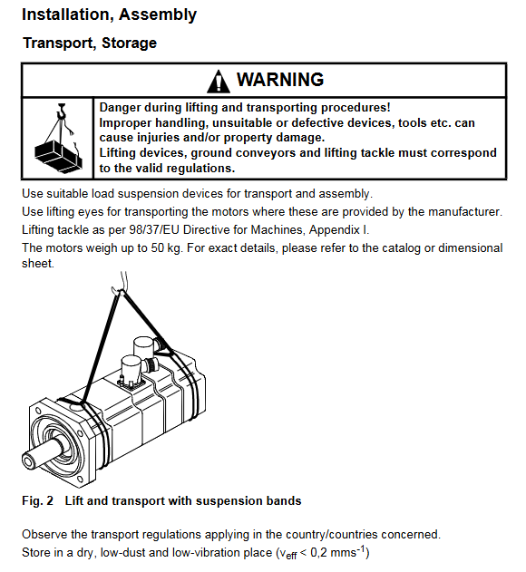
The maximum weight of the motor is 50kg, and lifting devices that comply with Appendix I of the 98/37/EEC Machinery Directive (such as lifting rings and slings) must be used for handling. It is prohibited for a single person to handle in violation of regulations.

Product Core Information: Attributes, Applications, and Delivery

(1) Core attributes of the product

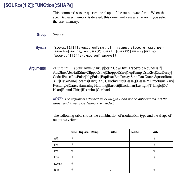
The 1FK6 series motor is a permanent magnet excitation three-phase synchronous servo motor, with a core design adapted to the “sine current principle motor control pulse inverter”. Precise control of speed and torque needs to be achieved through a frequency converter, and direct connection to the three-phase power grid is prohibited (otherwise it will cause winding burnout and permanent magnet demagnetization). The motor adopts self cooling method, compact structure, suitable for high-precision driving and positioning scenarios, and has the characteristics of low noise, long life, and high protection level (IP64).

(2) Typical application scenarios

Mainly used for equipment with strict requirements for driving accuracy and response speed, including:

Machine tools (cutting, machining centers);

Automated production equipment;

Industrial robot;

Material handling devices (such as conveyors, robotic arms).

(3) Delivery scope and acceptance requirements

Delivery list: motor body (including integrated encoder, optional brake), separate product nameplate (to be attached near the equipment for reference), multilingual manual;

Acceptance criteria:

After receiving the goods, it is necessary to immediately verify the waybill with the physical object to confirm that there are no missing parts or transportation damage;

If any transportation damage is found, it is necessary to immediately claim compensation from the carrier; If there are component defects or incomplete deliveries, it is necessary to promptly contact the responsible representative of Siemens;

The instruction manual should be properly stored in an easily accessible location near the equipment for easy operation and maintenance reference.

Key technical parameters: performance and adaptation indicators

(1) Infrastructure and protection parameters

Parameter category specific indicator standard basis

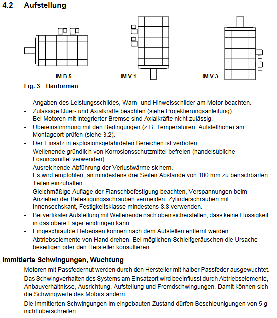
Installation form standard IM B5, optional IM V1, IM V3 EN 60034-7

Protection level IP64 (dustproof, splash proof), optional IP65 (enhanced dustproof and waterproof), drive end flange can be upgraded to IP67 EN 60034-5

Cooling method: self cooling (no additional cooling device required) EN 60034-6

Design standard for shaft end: keyway free cylindrical shaft (tolerance k6); Optional: with keyway+key (tolerance k6, half key balance) DIN 748-3, IEC 60072-1

(2) Electrical and Performance Parameters

Parameter category specific indicator standard basis

Insulation class F (maximum allowable operating temperature 155 ℃) EN 60034-1

Braking parameters: normally closed holding brake (optional), power supply voltage 24V DC ± 10%, power 15W DIN VDE 0580

Speed range: Rated speed (nN) ≤ 3000rpm, maximum speed (nmax) ≤ 5300rpm, as indicated on the product nameplate

Torque parameters: Zero speed continuous torque (M0) up to 6.0Nm, rated torque (MN) up to 4.0Nm, as indicated on the product nameplate

Current parameters: Rated current (IN) up to 4.3A, zero speed current (I0) up to 3.1A, as indicated on the product nameplate

Noise level 1FK6 03./04.: ≈ 55dB (A); 1FK6 06.:≈65dB (A); 1FK6 08./10.: ≈ 70dB (A) (below 3000rpm) EN 60034-9

(3) Environmental and lifespan parameters

Parameter category specific indicator standard basis

Environmental temperature operation: -15 ℃~+40 ℃; Exceeding the range requires derating (power factor 0.92 at 50 ℃, power factor 0.82 at 60 ℃) EN 60034-1

Altitude adaptation ≤ 1000m (standard); 2000m power factor 0.942500m power factor 0.9 EN 60034-1

Bearing lifespan Rolling bearings (lifetime lubrication), reference lifespan 20000h Siemens design specifications

Radial shaft seal lifespan of approximately 5000 hours under oil lubrication conditions according to Siemens design specifications

Vibration tolerance vibration acceleration ≤ 5g, vibration level N EN 60034-14

(4) Optional configuration parameters

Encoder system: incremental encoder (sin/cos 1VPP), absolute encoder (EnDat protocol), simple absolute encoder, rotary transformer;

Additional components: planetary gearbox, normally closed holding brake;

Protection upgrade: IP65 protection level, IP67 protection for drive end flange.

Installation and Connection: Specifications and Key Requirements

(1) Transportation and Storage Standards

Transportation requirements:

Use appropriate lifting devices (such as slings and rings) to avoid tying the motor shaft or flange directly with ropes and prevent damage to components;

During transportation, it is necessary to fix it firmly, avoid severe bumps or impacts, and prevent the permanent magnet from shifting;

Comply with local transportation regulations, clarify that the motor is a “strong magnet containing equipment”, and avoid magnetic interference issues during air transportation.

Storage conditions:

The storage environment needs to be dry, low dust, and low vibration (effective vibration speed)v eff<0.2mm/s);Avoid direct sunlight or high temperature and humidity environments to prevent the winding from getting damp or the performance of the permanent magnet from deteriorating;

Before storage, remove the rust inhibitor at the shaft end (using commercial solvents) to avoid affecting subsequent installation.

(2) Mechanical installation requirements

Installation gap: At least three sides of the motor need to reserve a 100mm heat dissipation gap to ensure self cooling effect;

Fixed specifications:

Use hexagon socket head screws with a strength grade of ≥ 8.8 to fix the flange, and tighten them evenly (to avoid flange deformation);

The screw torque must meet the equipment requirements, and excessive tightening is prohibited to cause thread damage;

Load limit:

Motors with integrated brakes are prohibited from bearing axial forces, and radial forces must strictly follow the requirements of the project planning guidelines;

When installing vertically (with the shaft end facing upwards), protective measures should be taken to prevent liquid from seeping into the upper bearing;

Balance requirements:

Motors with keyways are already balanced with half keys when they leave the factory. After installing output components such as couplings and gears, they need to be rebalanced according to ISO 1940 standards;

Do not strike the motor shaft or bearings. Special tools (such as a puller) should be used to install/remove the output components. If necessary, the output components can be heated (to avoid high temperature conduction to the inside of the motor).

(3) Electrical Connection Specification

Cable selection:

Pre assembled shielded cables recommended by Siemens must be used (not within the scope of delivery), and power cables and signal cables must be laid separately to avoid electromagnetic interference;

The cable should be compatible with the rated voltage and current of the motor, and have sufficient mechanical strength to avoid pulling and damaging it;

Plug connection:

The plug types are divided into power plug (P) and signal plug (S), and the wiring must strictly follow the drawing (Fig.5), and misconnection is prohibited;

The plug torque must comply with the specifications (power plug: 12Nm/20Nm, signal plug: 12Nm), and excessive twisting is prohibited;

The direction of the plug can be adjusted up to 10 times (when equipped with a matching socket) to avoid cable fatigue damage;

The inside of the plug should be clean and free of residue and moisture, and the sealing surface should be intact to ensure an IP64 protection level;

Grounding and shielding:

The protective conductor (PE) must be reliably grounded, and the grounding resistance must comply with local electrical regulations;

The cable shielding layer needs to be grounded at both ends to reduce high-frequency harmonic radiation and avoid electromagnetic interference (EMC);

Special requirements:

The encoder and temperature sensor are electrostatic sensitive components, and touching their connection terminals with hands or tools with static electricity is prohibited;

The temperature sensor can only cope with conventional overheating scenarios, and an additional thermal overload relay needs to be configured when the motor is stationary and overloaded.

Start up, operation and maintenance, and troubleshooting

(1) Pre startup inspection

Electrical connection inspection: Confirm that all plugs are securely fastened, the wiring is correct, and there are no loose or short circuit hazards;

Mechanical state inspection: manually rotate the motor output component to confirm that there is no jamming or friction noise, and that the keyway (if any) is fixed;

Protection device inspection: Motor overload protection, temperature protection and other devices have been activated and function normally;

Environmental condition inspection: The installation environment temperature and altitude meet the requirements, and the heat dissipation gap is sufficient;

Auxiliary equipment inspection: The supporting equipment such as frequency converter and encoder have been debugged and the parameters are adapted to the characteristics of the motor.

(2) Start the process

Brake test (with brake motor): Apply 24V DC ± 10% voltage to brake pins BR and BR2 to confirm that the rotor can rotate freely without friction noise;

Inverter startup: Start the system according to the instructions of the inverter (such as SIMODRIVE, MASTERDRIVES MC), and the initial speed should be lower than the rated speed;

Operation monitoring: Observe the operation status of the motor, confirm that the speed and torque meet the requirements, and there is no abnormal vibration, noise, or overheating;

Positioning test (positioning scenario): Verify that the encoder signal is normal and the motor positioning accuracy meets the standard;

Emergency stop test: Trigger the emergency stop button, confirm that the brake and frequency converter are linked normally, and the motor can quickly stop.

(3) Daily maintenance and cycle requirements

Cleaning and maintenance: Regularly clean the dust and oil stains on the surface of the motor to ensure effective heat dissipation. Power off during cleaning to prevent water or cleaning agents from seeping into the interior of the motor;

Status check:

Regularly inspect cables and plugs for damage, aging, and loose fasteners;

Monitor the operating temperature, vibration, and noise of the motor, and promptly shut down for troubleshooting if any abnormalities are found;

Periodic maintenance reference:

Bearing: The reference life is 20000 hours. If there is abnormal noise or increased vibration during operation, it should be replaced in a timely manner;

Radial shaft seal (oil lubrication): with a reference life of 5000 hours, regularly check for leaks and replace if necessary;

Special maintenance: After disassembling the motor, the encoder system must be recalibrated, otherwise it will affect the positioning accuracy.

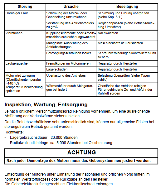
(4) Common faults and solutions

Core causes of fault phenomena and solutions

Irregular motor operation: 1. Insufficient shielding of motor/encoder cables, electromagnetic interference; 2. The gain of the frequency converter controller is too high. 1. Check if the grounding of the cable shielding layer is reliable; 2. Reduce the controller gain according to the frequency converter manual

Severe motor vibration: 1. Coupling/load imbalance; 2. Poor alignment of the drive chain; 3. Loose fixing screws. 1. Rebalance the load and coupling components; 2. Calibrate the coaxiality of the drive chain; 3. Check and tighten all fasteners

Abnormal operating noise (abnormal noise): 1. Foreign objects enter the interior of the motor; 2. Bearing wear or damage; 3. Permanent magnet displacement: 1. Stop the machine for inspection and remove foreign objects; 2. Replace the bearings; 3. Contact Siemens for professional maintenance

Motor overheating (surface temperature>140 ℃) 1. Load exceeding rated torque; 2. Insufficient heat dissipation gap or surface dust; 3. Temperature sensor malfunction: 1. Reduce the load to the rated range; 2. Clean the surface dust and increase the heat dissipation gap; 3. Repair or replace the temperature sensor

Encoder signal abnormality: 1. Encoder wiring error; 2. The encoder is subject to electromagnetic interference; 3. The encoder is damaged. 1. Check the wiring diagram and rewire it; 2. Strengthen cable shielding and grounding; 3. Replace the encoder and calibrate it

(5) Equipment Disposal Standards

When the motor is scrapped, it should be classified and recycled according to national/local regulations, or returned to Siemens for disposal. It is prohibited to dispose of it at will;

Encoders, brakes, and other electronic components need to be disposed of separately as electronic waste to avoid environmental pollution;

Before disposal, it is necessary to remove the permanent magnets inside the motor (operated by professionals) to prevent strong magnetic fields from causing harm to disposal personnel or equipment.

Siemens medium voltage vacuum switch technology and components

Basic Information

Siemens medium voltage vacuum switch technology and components are mainly aimed at the medium voltage power system and industrial application fields, providing a comprehensive introduction to vacuum switch technology and related components. The document mentions that all Siemens related products have passed ISO 9001 (Quality Management), ISO 14001 (Environmental Management), OHSAS 18001 (Occupational Health and Safety) system certification, and comply with international standards such as IEC (International Electrotechnical Commission) and IEEE (Institute of Electrical and Electronics Engineers). Some products are compatible with Chinese GB/DL standards.

Medium Voltage Core Concepts and Application Scenarios

1. Definition of voltage level

Medium voltage: AC voltage ranging from 1kV to 52kV, mainly used for power distribution and industrial networks;

Low voltage: AC voltage ≤ 1kV or DC voltage ≤ 1.5kV;

High voltage: used for power transmission (specific scope not specified in the document, focus on medium voltage).

2. Typical application scenarios

Common voltage levels for specific scenarios in the field

Power system power station (generator circuit, ≤ 24kV), primary distribution station (high voltage to medium voltage), secondary distribution station (medium voltage to low voltage) 10kV-40kV (distribution network)

Industrial plants (powered by motors), mining, ships, 3kV-15kV (motor operating voltage)

Special fields (traction power supply) Germany/Austria/Switzerland (AC 15kV, 16.7Hz), other regions (AC 25kV, 50Hz), DC railways (≤ 3kV) AC 15kV/16.7Hz, AC 25kV/50Hz

3. Operating stress of medium voltage equipment

Medium voltage equipment needs to withstand various operating stresses, which is the core basis for selection and design:

Dielectric loss strength: able to withstand normal operating voltage (including fluctuations) and overvoltage (operation/lightning overvoltage);

Current carrying capacity: continuously carrying normal current, short-term carrying overcurrent, and instantaneous carrying short-circuit current;

Current on-off: on-off normal current, fault current, and special current (capacitive/inductive current, high-frequency transient current);

Isolation requirements: In the disconnected state, the safety isolation distance specified by the standard must be met for easy maintenance;

Operation frequency: It is necessary to adapt to multiple on-off operations in a short period of time (such as multi segment reclosing of the recloser).

Core technology: Vacuum arc extinguishing technology

Vacuum arc extinguishing technology is the core of Siemens medium voltage switchgear, which has the advantages of high reliability, long life, and low maintenance. The specific characteristics are as follows:

1. Arc extinguishing principle

When the contacts separate in the vacuum arc extinguishing chamber, a metal vapor arc is generated, and current flows through the metal vapor plasma; The arc automatically extinguishes when the current crosses zero, and the remaining metal vapor loses conductivity within a few microseconds. The insulation ability of the contact gap quickly recovers (with a recovery speed of 5kV/μ s), and can immediately withstand external voltage.

2. Key technological advantages

Low current cutoff: Using special contact materials, the cutoff current is only 2A-3A, avoiding excessive overvoltage when small currents are turned on and off;

Low arc voltage: The arc voltage is only 20V-200V, with low arc energy, minimal contact wear, and long equipment life;

Maintenance free: The vacuum environment is free of oxidation and impurities, and the arc extinguishing system does not require regular maintenance.

3. Contact type and applicable scenarios

Contact type, structural characteristics, current adaptability range, advantages, application product examples

Radial magnetic field contact cup-shaped/spiral structure, generating radial magnetic field ≤ 10kA (diffusion arc); >10kA (contraction arc, arc rotation) universal circuit breaker (3AH5) to avoid local overheating and uniform wear of contacts

Axial magnetic field contact disc-shaped structure, generating high axial magnetic field current (arc always spreads), uniform force on the contact surface, no local melting, high-capacity circuit breaker (3AH3)

Classification and Technical Parameters of Medium Voltage Equipment

Medium voltage equipment is divided into switch devices (for current switching) and non switch components (for protection, measurement, and auxiliary functions). The specific classification and key parameters are as follows:

1. Switchgear

(1) Vacuum circuit breaker

Vacuum circuit breakers can switch between normal and short-circuit currents, suitable for indoor and outdoor scenarios. The core models and parameters are as follows:

Type, Model, Series, Applicable Scenarios, Key Parameters (Maximum), Operating Mechanism

Indoor Circuit Breaker SION 3AE General Scenario (Industrial/Distribution) Rated Voltage 24kV, Rated Current 2000A, Short Circuit Breaking Current 40kA Spring Energy Storage Mechanism

3AH5 economical type, rated voltage for small capacity scenarios is 17.5kV, rated current is 2000A, short-circuit breaking current is 31.5kA, spring energy storage mechanism

3AH3 high-capacity scenario rated voltage 40.5kV, rated current 4000A, short-circuit breaking current 63kA, spring energy storage mechanism/magnetic operation mechanism

3AH36/37/38 generator circuit rated voltage 24kV, rated current 8000A, short-circuit breaking current 72kA, spring energy storage mechanism

3AH47 traction power supply (1/2 pole) compatible with 16.7Hz/25Hz/50Hz/60Hz, mechanical life of 60000 times, spring energy storage mechanism

Outdoor circuit breaker 3AF0 (tank type) for outdoor distribution, rated voltage for harsh environments of 40.5kV, rated current of 2500A, short-circuit breaking current of 31.5kA, spring energy storage mechanism, compliant with IEC 62271-100 S2 level

SDV (Dead Can) outdoor power distribution, including anti arc rated voltage of 38kV, rated current of 3000A, short-circuit breaking current of 40kA, spring energy storage mechanism/magnetic operation mechanism

(2) Recloser (3AD series)

Function: Integrated switch unit and controller, can automatically detect faults and complete multi segment coincidence, reducing power outage time caused by temporary faults;

Core parameters: rated voltage ≤ 38kV, rated current ≤ 800A, short-circuit breaking current ≤ 16kA, typical coincidence sequence O-0.2s-CO-2s-CO-2s-CO;

Controller: Provides 7SR224 (Reyrolle series) and 7SC80 (SIPROTEC series), supports communication protocols such as IEC 61850 and MODBUS, and is compatible with smart grids.

(3) Vacuum contactor (3TL series)

Function: High frequency switching (≤ 3 million mechanical lifetimes), suitable for loads such as motors, transformers, capacitors, etc;

Core model parameters:

Model Rated voltage Rated current Mechanical life Electrical life (rated current) Suitable load type

3TL81 7.2kV 400A 1 million times 250000 times motor (AC-3/AC-4), transformer

3TL61 7.2kV 450A 3 million times 1 million times motor (AC-3/AC-4), capacitor

3TL65 12kV 400A 1 million times 500000 times motor (AC-3/AC-4), reactor

3TL71 24kV 800A 1 million times 500000 times large capacity motor and transformer

Contactor fuse combination (3TL62/63/66): Integrated high-voltage HRC fuse, short-circuit breaking current ≤ 50kA, suitable for high current scenarios (such as 450A rated current).

(4) Switch – Isolation switch

Arc extinguishing principle: using hard gas to extinguish the arc. When the arc is generated, the insulating material releases gas to quickly extinguish the arc (the gas is non renewable and the number of operations is lower than that of vacuum equipment);

Function: It combines the functions of switching (on/off load current) and isolation (safe isolation distance), with high cost-effectiveness;

Application scenario: Industrial distribution and substation auxiliary circuits require the use of fuses to achieve short-circuit protection.

2. Non switch components

(1) Lightning arrester and voltage limiter

Function: Protect equipment from lightning overvoltage (external) and operation/grounding fault overvoltage (internal) damage;

Core model parameters:

Type, Model, Applicable Scenarios, Rated Voltage (Maximum), Nominal Discharge Current, Shell Material

Voltage limiter 3EF motor, dry-type transformer, frequency converter 12kV 1kA polyethylene

Lightning arrester 3EK4 distribution network, medium voltage switchgear 45kV 10kA (AC) silicone rubber

Line lightning arrester 3EK7 outdoor line protection 72.5kV 10kA silicone rubber

(2) High voltage fuse (3GD series)

Function: Short circuit protection, which melts when the current exceeds the threshold, cuts off the fault current, and protects equipment such as transformers, motors, capacitors, etc;

Classification:

Backup fuse: suitable for 7.2kV-36kV, rated current 6.3A-315A, short-circuit breaking current 40kA-63kA;

Motor protection fuse: suitable for 7.2kV-12kV, rated current 50A-315A, short-circuit breaking current 50kA;

Installation: Supports 1-phase/3-phase installation and can be combined with switchgear (such as switch fuse combination).

(3) Protection and measurement transformers

Current Transformer (CT):

Function: Convert high current proportionally to low current (for measurement/protection equipment use) to achieve electrical isolation;

Key requirements: Cannot operate in an open circuit (to avoid overvoltage), can have multiple secondary windings (measurement/protection separated);

Types: Indoor support type, indoor sleeve type, outdoor type.

Voltage Transformer (VT):

Function: Convert high voltage proportionally to low voltage (for measurement/protection equipment use);

Key requirements: Do not short-circuit operation (to avoid overheating), some windings with residual voltage (ground fault detection);

Type: Indoor, Outdoor.

(4) Auxiliary switch (3SV9 series)

Function: Auxiliary contacts for mechanical operation, used for electrical interlocking, auxiliary contactor/coil control, and motor operating mechanism drive;

Key parameters: rated voltage 230V AC/240V DC, rated thermal current 10A, mechanical life 100000 times, electrical life 30000 times;

Configuration flexibility: Switching levels 2-26, contacts can be customized as normally closed (NC), normally open (NO), or switch contacts, supporting different switching angles and overlapping contacts.

Selection guide and cooperation support

1. Selection criteria

Select the appropriate equipment based on the operating scenario (normal operation/fault operation) and load type (inductive/capacitive/resistive), and provide a detailed selection table in the document (example: inductive load selection under normal operation scenario):

Load type, current range, and equipment adaptation notes

No load transformer ≤ 0.03I, circuit breaker, contactor, switch isolator, recloser with neutral grounding transformer

When the motor is running and the circuit breaker and contactor are started, the current is ≤ 7Ir (cos π≤ 0.3)

Compensation reactor ≤ 2000A, transient recovery voltage rise rate of circuit breaker ≤ 6kV/μ s

2. Siemens cooperation and support

Collaboration Plan: Provide standardized testing systems (compliant with IEC 62271-200), design drawings, technical consulting, production training, and software tools (engineering design/document management) for switchgear manufacturers;

Supporting equipment:

SIMOPRIME: Medium voltage air insulated switchgear, compatible with SION 3AE circuit breakers, 7.2kV-24kV;

SIVACON S8: Low voltage distribution panel, rated current ≤ 7000A, in compliance with IEC 61439-2;

TEKTRONIX CFG 253 Function Generator

Basic and Product Positioning

The official user manual for Tektronix CFG253 function generator (model 070-8362-04) states that the core purpose of the device is to generate various standard waveforms for audio equipment testing, ultrasound equipment calibration, servo system debugging, and other scenarios. It supports flexible adjustment of amplitude, frequency, waveform symmetry, as well as internal/external sweep functions to meet different testing needs.

Core parameters and functions

1. Key Electrical Characteristics

Parameter Category Specific Indicator Remarks

Normal frequency range (Freq/1): 0.3 Hz-3 MHz (7-speed RANGE: 1/10/100 Hz, 1/10/100 KHz, 1 MHz); 10 frequency division (Freq/10): 0.03 Hz -300 KHz Frequency accuracy: ± 5% Full scale (applicable to both normal and 10 frequency division)

Waveform types: sine wave, square wave, sawtooth wave, TTL synchronization signal. TTL signal is output from SYNC OUTPUT with fixed parameters

There are two selectable main output amplitudes (VOLTS OUT button switch):

1. Pop up mode: 0-20 V ₚₚ (open circuit), 0-10 V ₚₚ (50 Ω load)

2. Press the gear: 0-2 V ₚₚ (open circuit), 0-1 V ₚₚ (50 Ω load). The amplitude is continuously adjusted by the AMPLITUDE knob

DC offset ± 10 V (open circuit), ± 5 V (50 Ω load) Pull the DC OFFSET knob to activate, and when pressed, the offset is 0

Waveform quality sine wave distortion:<1% (10 Hz-100 KHz); Square wave rise/fall time: ≤ 100 ns (50 Ω load); Sawtooth wave linearity: ≥ 99% (20 Hz-200 KHz), ≥ 97% (200 KHz -3 MHz)-

Internal frequency scanning function: rate 0.5-50 Hz (SWEEP RATE adjustment), width 1:1-100:1 (SWEEP WIDTH adjustment); External sweep frequency: VCF INPUT input 0-+10 VDC, sweep frequency range 2 times (100:1). When performing external sweep frequency, the SWEEP button needs to pop up

2. Physical parameters

Specific indicators for parameter categories

Dimensions: Width 240 mm (9.46 in), Height 64 mm (2.53 in), Depth 230 mm (9.0 in)

Weight 2.0 kg (4.4 lb)

Safe operation and initialization

1. Safety regulations (must be followed)

Grounding requirements: The equipment should be grounded through the grounding conductor of the power cord. It is forbidden to remove the grounding pin of the power cord, otherwise it may cause electric shock; Before connecting the signal, it is necessary to confirm that the device is reliably grounded.

Line voltage and fuse:

The line voltage needs to be set to the appropriate value (supporting 4 levels: 90-110/108-132/198-242/216-250 VAC, 50-60 Hz). Setting it incorrectly can burn out the equipment;

Fuses need to be matched according to voltage: 0.3 A, 250 V, 3AG specifications (part number 159-0029-00) are used for 90-132 V operation, and 0.15 A, 250 V, 3AG specifications (part number 159-0054-00) are used for 198-250 V operation. Before replacement, the power must be turned off and the signal input disconnected.

Interface limitation: The VCF INPUT input voltage of the rear panel can reach a maximum of ± 10 V ₚₖ. Exceeding this range may damage the internal circuit.

Environmental taboos: Do not operate in damp or explosive environments; Do not operate with the cover open (as it may come into contact with high-voltage components, causing electric shock or fire).

2. Initialization operation steps

Set line voltage: Adjust the equipment line voltage selector (position shown in Figure 1) according to the local power supply voltage to ensure it matches the power supply voltage.

Check the fuse: Open the fuse cover and confirm that the installed fuse specifications are compatible with the line voltage. If the specifications are incorrect, replace it.

Connect power supply: Use the device’s designated power cord (standard configuration is 115V North American model, other regions require corresponding accessories, refer to Table 7), and plug it into a grounded power outlet.

Power on check: Press the POWER button, confirm that the POWER On Light is on, and the device enters standby mode.

Panel controls and interface functions

1. Front panel controls (Figure 2)

Control Number Control Name/Function Operation Instructions

1 POWER ON Light indicator light on → Device powered on, off → Power off or malfunction (such as blown fuse)

2 AMPLITUDE knob adjusts the amplitude of the main output signal, with the range determined by the VOLTS OUT button (0-2 V ₚₚ or 0-20 V ₚₚ)

Press the 3 DC OFFSET knob → DC offset is 0; Pull on → Adjust the DC level of the main output signal (range ± 10 V open circuit)

The SYMMETRY knob only takes effect when the SYMMETRY button is pressed: adjust the square wave duty cycle, sawtooth wave/sine wave rise and fall time

5 RANGE (Hz) button (7 levels: 1/10/100 Hz, 1/10/100 KHz, 1 MHz) to select the frequency range, such as pressing “1 K” → frequency range 0.3 KHz -3.0 KHz

Press the corresponding button (sine wave/square wave/sawtooth wave) to select the desired waveform for the main output

Within the selected range of the RANGE button, continuously fine tune the output frequency with the 7 FREQUEncy knob

The 8 SWEEP WIDTH knob only takes effect when the SWEEP button is pressed internally: adjust the sweep amplitude (1:1-100:1)

The 9 SWEEP RATE knob only works when scanning internally: adjust the scanning rate (0.5-50 Hz)

Press the 10 SWEEP button → Enable internal sweep frequency; Pop up → Enable external sweep (controlled through VCF INPUT)

Press the SYMMETRY button → Output frequency ÷ 10, and activate the SYMMETRY knob function at the same time; Pop up → Normal frequency, knob failure

Press the 12 VOLTS OUT button → amplitude range 0-2 V ₚₚ (50 Ω load 0-1 V ₚₚ); Pop up → amplitude range 0-20 V ₚₚ (50 Ω load 0-10 V ₚₚ)

13 SYNC (TTL) OUTPUT (BNC interface) outputs TTL synchronization signal with fixed amplitude and DC offset (not affected by AMPLITUDE/DC OFFSET knob)

14 MAIN OUTPUT (BNC interface) outputs sine wave/square wave/sawtooth wave signals, with parameters adjusted by corresponding controls

Press the POWER button to turn on the device; Press again → Shut down

2. Rear panel interface (Figure 3)

Interface Name Function Description

VCF INPUT (BNC) external sweep frequency input interface: Input 0-+10 VDC signal, control the main output frequency sweep (range of 2 times ten)

Core Function Operation Guide

1. TTL signal generation

The TTL signal parameters (amplitude, DC offset) comply with the TTL standard and cannot be adjusted. The operation steps are as follows:

Connect the oscilloscope input to the SYNC (TTL) OUTPUT interface of CFG 253 using a BNC cable;

Press the POWER button to turn on the device, use the RANGE button to select the frequency range, and rotate the FREQUEncy knob to fine tune the frequency;

Observe oscilloscope waveform: Rotate the DC OFFSET or AMPLITUDE knob, and the waveform remains unchanged (TTL signal parameters are fixed).

2. External frequency scanning operation

External frequency scanning requires controlling the scanning parameters through an external voltage source. The steps are as follows:

Connect the MAIN OUTPUT of CFG253 to the oscilloscope input using a BNC cable, and connect the external voltage source to the VCF INPUT (rear panel) of CFG253 using a BNC cable;

Rotate the SWITCHY knob to the “0.3” position (ensuring that the sweep range covers the required area);

Pop up SWEEP button (turn off internal sweep and enable external control);

Adjust the output of the external voltage source (0-+10 VDC), and observe the frequency change of the main output with an oscilloscope: voltage increase → frequency decrease, voltage decrease → frequency increase, with a sweep frequency range of 2 harmonics (100:1).

3. Adjustment of waveform symmetry

Symmetry adjustment can change the “asymmetry degree” of the waveform, which only takes effect when the SYMMETRY button is pressed. The steps are as follows:

Press the Function button to select the target waveform (square wave/sawtooth wave/sine wave);

Press the SYMMETRY button (at this point, the output frequency will automatically ÷ 10, such as the original 100 Hz → 10 Hz);

Rotate the SYMMETRY knob:

Square wave: clockwise → duty cycle increases (high-level time prolongs), counterclockwise → duty cycle decreases (low-level time prolongs), center position → duty cycle 50%;

Sawtooth wave: clockwise → increase rise time, decrease time, counterclockwise opposite;

Sine wave: clockwise → positive half cycle time prolongs, negative half cycle shortens, counterclockwise is the opposite.

Maintenance and Accessories

1. Daily maintenance

Cleaning:

After the power is cut off, use a soft cloth dipped in a mixture of “mild detergent+water” to wipe the surface of the equipment;

It is prohibited to directly spray cleaning agents onto the equipment (which may seep into the interior and damage the circuit);

Do not use solvents or abrasives containing benzene, toluene, acetone, or xylene (which can corrode the casing/scratch the panel).

Transport packaging:

If there is no original packaging, choose corrugated cardboard boxes with internal dimensions at least 3 inches larger than the equipment;

Put the equipment into a plastic bag (to prevent moisture and loose fillers from entering);

Fix the equipment with foam, bubble film and other materials to avoid shaking during transportation;

Seal the cardboard box with packing tape to ensure firmness.

Troubleshooting:

Problem: After pressing the POWER button, the POWER On Light does not light up;

Troubleshooting: After power failure, disconnect all signal cables, open the fuse cover to check if the fuse is blown. If it is blown, replace it with a new fuse of the corresponding specification (refer to the fuse specifications in the “Safety Regulations”).

2. Accessories List

(1) Standard accessories (shipped with equipment)

Accessory Name Tektronix Part Number Applicable Scenarios

3AG fuse (0.3 A, 250 V) 159-0029-00 90-132 VAC power environment

115 V power cord reference table 7 North American 115 V power supply

CFG 253 User Manual 070-8362-XX Equipment Operation and Maintenance Guide

(2) Optional accessories (additional order required)

Accessory Name Tektronix Part Number Applicable Scenarios

3AG fuse (0.15 A, 250 V) 159-0054-00 198-250 VAC power environment

230 V power cord (regional adaptation) reference table 7: Europe, UK, Australia and other 230 V regions

(3) Regional compatible power cord specifications (Table 7)

Plug type applicable region Tektronix part number

North American standard plug North American (115 V) 161-0104-00

European standard plug Europe (230 V) 161-0104-06

British Standard Plug UK (230 V) 161-0104-07

Australian Standard Plug Australia (230 V) 161-0104-05

North American 230 V plug North American (230 V) 161-0104-08

Swiss standard plug Switzerland (230 V) 161-0167-00

TEKTRONIX P6022 Current Probe

Basic Information and Product Positioning

This document is the official manual for the Tektronix P6022 current probe (document number 070-0948-05). Its core function is to convert the AC current waveform into a voltage signal that can be measured by an oscilloscope, enabling current measurement without disconnecting the tested circuit. It is suitable for grounded general-purpose oscilloscopes with an input impedance of 1 M Ω and is mainly used in scenarios that require high-precision and wide frequency range current detection.

Core parameters of the product

1. Key electrical parameters (including guaranteed and typical characteristics)

Parameter Category Specific Indicator Remarks

Sensitivity options are available in two levels: 1 mA/mV and 10 mA/mV, controlled by the terminal sensitivity switch

Bandwidth (-3 dB) 1 mA/mV range: 8.5 kHz -100 MHz; 10 mA/mV range: 935 Hz-120 MHz requires an oscilloscope with a bandwidth ≥ 300 MHz

Intermediate frequency accuracy ± 3% calibration environment: 20 ° C-30 ° C (68 ° F-86 ° F)

Maximum current pulse current: 100 A peak (≤ 9 A · ms, if exceeded, the magnetic core will saturate); Continuous current: The reference frequency derating curve is 6 A p-p in the range of 3 kHz to 10 MHz at 10 mA/mV

Insertion impedance ≤ 0.03 Ω at 1 MHz and ≤ 0.2 Ω at 120 MHz affects high-frequency signal measurement, and attention should be paid to load effects

Rise time 1 mA/mV ≤ 3.2 ns; 10 mA/mV ≤ 2.9 ns reflects high-frequency response speed

Signal delay of about 9 ns with 5-foot probe cable and terminal

2. Environmental and mechanical parameters

Specific indicators for parameter categories

Working temperature: 0 ° C-50 ° C (32 ° F-122 ° F); Non working temperature: -40 ° C -65 ° C (-40 ° F -149 ° F)

Working altitude 2000 m (6561 ft); Non working altitude: 15240 m (50000 ft)

Cable length 5 feet (1.5 meters)

Weight probe+cable: 2.5 oz (≈ 71 g); Terminal: 1.7 oz (≈ 48 g)

The maximum wire diameter of 0.11 inches (2.79 mm) exceeding the specification will damage the probe clamp

Safety operation standards

1. General safety warning

Maintenance restrictions: Only qualified personnel are allowed to carry out repairs, avoiding separate operations. Before repairing, the power must be disconnected and refer to the safety summary.

Connection taboos: Do not plug or unplug probes/test wires with power on; The connection sequence is “connect the terminal to the oscilloscope first, then connect the probe to the circuit”, and the disconnection sequence is reversed; The common terminal of the probe can only be grounded, and it is prohibited to connect to voltages higher than the ground potential.

Usage environment: Do not open the lid or use in damp/explosive environments; When measuring with bare wires, the voltage should not exceed 30 Vrms, 42 Vpk, or 60 VDC. Insulated wires are required above this voltage.

2. Probe operation safety

Sliding operation: When opening the sliding block, it should be held, and after placing the wire, it should be closed and locked (pushed to the transformer end about 1/8 inch) to ensure good contact between the two halves of the transformer.

Terminal protection: When measuring high currents, it is forbidden to disconnect the probe from the terminal (otherwise the secondary of the transformer will generate high voltage, causing electric shock or equipment damage).

Installation and usage guide

1. Installation steps

Terminal connection: Connect the BNC female head of the terminal to the probe output cable, and connect the BNC male head to the BNC input interface of the oscilloscope.

High frequency grounding: When measuring signals of ≥ 2 MHz, attach a 6-inch grounding wire to the probe transformer column and clamp it to RF ground to reduce interference and ringing.

Probe clamping: Open the slider → Place the measured wire into the transformer core (arrow direction is consistent with current direction, ensure correct waveform direction) → Close and lock the slider.

2. Usage skills

Reduce load effect: Prioritize clamping the probe at the low potential or ground terminal of the component to reduce its impact on the tested circuit.

Improve sensitivity: Increase the number of turns of the wire around the probe (e.g. 2 turns), doubling the sensitivity (e.g. 10 mA/division → 5 mA/division), but note that impedance increases with the square of the turns, which may affect high-frequency signals.

Anti magnetic field interference: In a strong magnetic field environment, use two probes to connect the positive and negative inputs of the oscilloscope, one clip the tested wire and one empty clip, and set the oscilloscope to “subtraction mode” to cancel out interference.

Performance validation and calibration

1. Required equipment

Equipment name, specification requirements, recommended model

Oscilloscope bandwidth ≥ 300 MHz, vertical sensitivity ≥ 1 mV/div, supports average amplitude TDS 303X, TDS 305X

Calibration generator fast edge (≤ 1 ns), sine wave (5 V) p-p@50 Ω, 935 Hz-120 MHz) Wavetek 9100, Tektronix PG 506A

Digital multimeter (DMM) AC voltage range, with an accuracy of 5.5 digits or higher, and an error of ≤ 0.5% at 50 kHz. Keithley 2000, HP 3458A

Auxiliary accessories BNC “T” type adapter, 50 Ω precision coaxial cable (36 inches), BNC to double banana head adapter, calibration fixture Tektronix corresponding models (see Table 6)

2. Core validation projects (including calculation methods)

(1) Mid frequency accuracy test (50 kHz)

Qualification criteria for step calculation method

1. Set the terminal to 1 mA/mV, calibrate the generator output to 50 kHz, 5 V p-p, connect BNC “T” → DMM, record the reading M1 I test=M1/50 Ω (test current). 2. Disconnect the DMM from “T”, connect the probe+terminal, calibrate the probe clamp fixture, record the DMM reading M2% Error=[(M2 − I test)/I test] × 100 ± 3%

3. Set the terminal to 10 mA/mV, repeat step 2, and record the DMM reading M3% Error=[(10 × M3 − I test)/I test] × 100 ± 3%

(2) Low frequency bandwidth test

Qualification criteria for sensitivity gear step calculation method

1 mA/mV 1. Measure the output M1 at 50 kHz; 2. Set the generator to 8.5 kHz and measure the output M2 low-frequency ratio=M2/M1 ≥ 0.707

10 mA/mV 1. Measure the output of M3 at 50 kHz; 2. Set the generator to 935 Hz and measure the low frequency ratio of M4 output=M4/M3 ≥ 0.707

(3) High frequency bandwidth testing

Qualification criteria for sensitivity gear step calculation method

1 mA/mV. Set the oscilloscope to 20 mV/div and measure the amplitude M1 at 50 kHz. 2. Set the generator to 100 MHz and measure the amplitude M2. High frequency ratio=M2/M1 ≥ 0.707

10 mA/mV. 1. Set the oscilloscope to 2 mV/div and measure the amplitude M3 at 50 kHz. 2. Set the generator to 120 MHz and measure the amplitude M4. High frequency ratio=M4/M3 ≥ 0.707

3. Calibration adjustment (if verification fails)

Remove terminal cover: Use a small screwdriver to gently pry open the top snap cover of the terminal (keep the bottom cover).

Oscilloscope settings: CH1, DC coupling, 2 mV/div, 4-5 ns/div, average 5-10 times, trigger set AC, positive slope.

Adjust parameters: calibrate the generator to output a 1 V p-p fast edge signal and connect it to the calibration fixture; Adjust the C28 and C29 capacitors of the terminal and the R10 resistance of the probe to minimize waveform distortion and ensure optimal flat top response.

Maintenance and Repair

1. Daily maintenance

Cleaning: Wipe the probe body with a damp cloth; Clean the magnetic core with cotton swabs soaked in isopropanol (solvents such as benzene, toluene, acetone, etc. are prohibited); Do not soak or use abrasives.

Lubrication: The slider component can only be coated with a small amount of silicon-based grease, and petroleum based grease is prohibited; Lubrication is prohibited on the contact surface of the magnetic core.

Inspection: Regularly check the wear of the slider and the cleanliness of the magnetic core contact surface (dirt can reduce low-frequency response).

2. Disassembly and maintenance

(1) Probe disassembly (requires soldering iron)

Pull back the strain relief boot, gently pry on the probe body and remove it forward.

Take out the ball bearing and spring retainer, and remove the upper half of the slider, spring, and transformer.

Remove the grounding terminal of the circuit board and gently remove the circuit board, transformer, and cable components (to avoid damaging the cable solder joints).

(2) Terminal maintenance

Replace connector: remove cover → protect circuit with heat sink → solder off old connector → replace with new connector → solder reset.

Replace the circuit board: Remove the front and rear covers → solder off the connector wires → remove the circuit board screws → assemble in reverse after replacement.

3. List of replaceable parts (core)

Electrical components (excerpt from Table 10)

Component Number Tektronix Part Number Name and Description

A1 670-1112-00 Probe Circuit Board Component

A2 011-0106-00 P6022 Coaxial Terminal

A1T1 120-0603-00 Current Transformer

A2C28/A2C29 281-0123-00 Variable capacitor (5-25 PF, 100 V)

Mechanical components (excerpt from Table 11)

Drawing number/index Tektronix part number name and description quantity

12-1 204-0360-01 Probe Upper Shell 1

12-3 351-0174-00 Probe Slide (Acetal Material) 1

12-9 175-1027-00 RF Cable Assembly (62.5 Ω, 60 inches) 1

12-18 196-3120-01 Probe Grounding Wire (23 AWG, 6 inches) 1

Tektronix AWG70000 series arbitrary waveform generator

Product Overview

Product coverage: AWG70000 series full models (such as AWG70001 single channel, AWG70002 dual channel), supporting software version 7.0 and above.

Compliance certification: Complies with EN 61010-1, UL 61010-1, CSA C22.2 No. 1010.1 safety standards to ensure compliance in industrial use.

Remote control setup: Ethernet and GPIB

1. Ethernet control (recommended)

(1) Hardware connection

Connect the Ethernet port of the instrument Rear panel to the LAN switch/PC using an RJ-45 Ethernet cable, supporting speeds of 10BASE-T (10Mbps), 100BASE-TX (100Mbps), and 1000BASE-T (1Gbps).

(2) Protocol and Configuration

Protocol type requirements for application scenarios

VXI-11 Server instrument and PC are both equipped with TekVISA standard remote control, with strong compatibility

Both the Raw Socket instrument and PC are equipped with TekVISA high-speed data transmission and low latency

DHCP is enabled by default for IP acquisition, and the IP is automatically obtained from the router. If a fixed IP is required, the laboratory’s fixed network environment can be modified through Windows network settings

2. GPIB control (compatible with traditional devices)

(1) Hardware connection

Instrument Rear panel USB 2.0 HS Device port → connect to the host port of TEK-USB-488 adapter;

Connect the GPIB port of the adapter to the GPIB card/interface of the PC using a GPIB cable.

(2) Key configuration rules

Address uniqueness: Each device on the bus must be assigned a unique address (1-30), which cannot be duplicated;

Bus limitation: Up to 15 devices can be connected, with 1 device required every 2 meters (6 feet), and the total cable length should be ≤ 20 meters (65 feet);

Power requirement: At least 2/3 of the equipment should be powered on to avoid signal attenuation;

Topology: Only supports star or linear connections, and prohibits ring/parallel connections.

(3) Address modification steps

Instrument end: Go to Utilities → System → GPIB Address, set a new address (default 1);

Restart adapter: Disconnect and reconnect the TEK-USB-488 adapter to ensure the new address takes effect.

Command syntax specification: SCPI standard and execution mechanism

1. Core grammatical symbols

Example of symbol meaning

<>Defined element (required)<wfm_name>(waveform name)

Defined as<Block>::=#<NZDig><Dig>… (Block Data Definition)

`XOR (choose one) ON OFF (choose one)

{} Required group (choose one) ` {INTernal EXTernal} ` (required internal/external)

[] Optional section [:]<Header>(colon optional)

… The preceding elements can be repeated<Argument>[,<Argument>…] (multi parameter)

() Comment #<NZDig>(non-zero digits)

2. Command and Query Structure

(1) Command (modify settings/execute actions)

Format: [:]<Header>[<Space><Argument>[<Comma><Argument>…]

Example: CLOCk: SURce INTernal (set clock source to internal)

(2) Query (Get Status/Data)

Format: [:]<Header>? [<Space><Argument>[<Comma><Argument>…]]

Example: CLOCk: SURce? (Query the current clock source)

3. Parameter types and rules

Example of Parameter Type Description

Boolean 0/OFF (false), 1/ON (true) AWGControl: DLOading: ENABle 1 (enable dynamic loading)

Discrete fixed options (such as MIN/MAX) FGEN: CHANnel1: AMPCrude MAX (amplitude set to maximum)

Numerical values (NR1/NR2/NR3/NRf) NR1 (integer, such as 123), NR2 (decimal, such as 12.3), NR3 (scientific counting, such as 1.23E3), NRf (flexible format) CLOCk: SRATE 25E9 (sampling rate 25GS/s)

String needs to be enclosed in single/double quotes MMEMory: OPEN “C: \ waveform. wfmx” (load file)

Arbitrary Block: Binary data block in the format of #<NZDig><Dig>…<DChar>… WLILD: WAVeform: DATA “TestWfm”, # 41024xxxx… (transmitting 1024 points of data)

4. Command execution mechanism

(1) Three types of commands

Example of Type Characteristics

Execute the next command OUTPut1: STATe ON only after the previous command is completed; OUTPut2: STATe ON (First turn on CH1, then turn on CH2)

During the execution of the blocking command, other commands are prohibited, which takes a long time. CALibration [: ALL] (full calibration, waiting for completion)

Overlapping commands can be executed concurrently with other commands, and it is necessary to manually ensure the completion of DIAGnostic: STARt (diagnostic startup, requires OPC)? Confirmation completed)

(2) Key Execution Rules

Abbreviation rule: Commands can be abbreviated, with the capitalized part being the abbreviation core (such as TRIGger: LEVel → TRIG: LEV);

Splicing rules: Use; Splicing multiple commands, different root nodes need to add: (such as TRIG: SUR EXT; :SOUR1:RMODe TRIG);

Termination symbol: When sending commands, EOI (last byte assertion) should be used as the termination symbol, and the instrument response should be terminated with LF+EOI;

Clear command: * CLS clears all event registers and queues, Device Clear (DCL) resets the command reception status.

Detailed explanation of core command group (selected high-frequency group)

1. Clock group (CLOCk): controls sampling rate and synchronization

Example of Command Function Parameter Range

CLOCk: SURce sets clock sources INTernal (internal), EFIXed (external fixed 10MHz), EVAReliable (external variable), EXTernal (external clock input) CLOCk: SURce EXTernal

CLOCk: Set the sampling rate AWG70001:1.49kS/s-50GS/s for SRATE; AWG70002:1.49kS/s-25GS/s CLOCk:SRATe 25E9(25GS/s)

CLOCk: PHASe: AJust: DEGREEs phase adjustment (degrees) -10800 °~10800 ° CLOCk: PHASe: AJust 90 (adjusted by 90 degrees)

CLOCk: JITTer jitter suppression switch 0/OFF, 1/ON CLOCk: JITTer ON (enable jitter suppression)

2. Sequence group (SLISt): Create multi-step waveform sequences

(1) Example of Core Command

Create sequence: SLISt: Sequence: NEW “Seq1”, 10,2 (Create “Seq1”, 10 steps, 2 tracks);

Set the number of steps to be repeated: SLISt: Sequence: STEP1: RCCount 5 (repeat Step 1 5 times);

Assign waveforms to steps: SLISt: Sequence: STEP1: TASSet1: WAVeform “Sine1” (Step 1 assigns “Sine1” waveform to track 1);

Query sequence length: SLISt: SEQ: LENGth? Seq1 “(returns the total number of steps taken by Seq1).

(2) Key Limitations

Maximum steps: 16383 steps per sequence;

Maximum number of tracks: 8 tracks per sequence;

Maximum number of repetitions per step: 1048576.

3. CALibration: Ensure measurement accuracy

Command function precautions

CALibration [: ALL] executes full calibration blocking command, cannot be aborted, returns 0 (success)/-340 (failure) upon completion

CALibration: To restore factory calibration constants, enter calibration active mode (ACTive: MODE CALibration)

CALibration:LOG? Query calibration log with timestamp and result (PASS/FAIL), maximum 64K characters

CALibration:RUNNing? Querying the current calibration process returns’ Subsystem: Region: Step ‘(e.g.’ Channel1: Dc: Compliance ‘)

4. S-parameter group (WLイ: PARAMeter): signal integrity optimization

(1) Mode switching

Command: WLVNet: PARAMeter: MODE {CASC | NCAS} (CASC=Cascade, NCAS=Non Cascade);

Cascade mode: Supports cascading up to 6 S-parameter files, suitable for complex links;

Non cascading mode: only 1 S parameter file, suitable for simple links.

(2) Port configuration (taking non cascaded as an example)

Command: WLVNet: PARAMeter: NCASCAding: TYPE 4 (set to port 4);

Signal type: WLVNet: PARAMeter: NCASCAding: TYPE {VICTim | AGGRessor | BOTH} (victim/interferer/both);

Embedding: WLILD: PARAMeter: NCASCAding: DEEMBed 1 (Enable embedding to correct link loss).

Status and Event System: Monitoring Instrument Operation

1. Four major register groups

(1) Status Byte Register (SBR)

Function: Summarize all 8-bit registers of states through * STB? Query;

Key position definition:

Bit7 (OSS): Operation status summary (events after OENR mask);

Bit6 (MSS/RQS): Main status summary (with service requests);

Bit5 (ESB): Standard Event Summary (SESR has new events);

Bit4 (MAV): Message available (output queue with data);

Bit3 (QSS): Suspicious Status Summary (Events after QENR Mask).

(2) Standard Event Status Block (SESB)

Contains two registers:

SESR (Standard Event Status Register): Record power, error, and other events through ESR? Query;

ESER (Event Status Enable Register): Mask SESR events, set through * ESE.

SESR key position:

Bit7 (PON): Power on;

Bit5 (CME): Command error (such as syntax error);

Bit4 (EXE): Execution error (such as parameter out of range);

Bit0 (OPC): Operation completed (triggered by OPC command).

2. Two types of queues

(1) Output queue

Function: FIFO structure, storing response data for query commands;

Trigger condition: After the query is executed, the data is stored in the queue, and the MAV bit of SBR is set to 1;

Clearing rule: Automatically clear when receiving new commands/queries, unread data will result in errors.

(2) Event queue

Function: FIFO structure, storing instrument events (errors, status changes, etc.);

Capacity limit: Up to 32 events, if exceeded, replace the 32nd event with -350, “Queue Overflow”;

Query method: SYSTem: ERRor [: NEXT]? (Read the next one) SYSTem:ERRor:ALL? (Read all).

Appendix Key Content

1. Appendix A: Character Table

A hexadecimal/decimal value that covers 7 ASCII characters, including control characters (such as LF=0A hex) and printable characters (such as A=41 hex), used as a character encoding reference for command transmission.

2. Appendix B: Original Socket Specification

Define communication parameters for the Raw Socket protocol:

Port number: 5025 (default);

Data format: ASCII, with each line terminated by \ n;

Timeout setting: It is recommended that the client set a 10 second timeout to avoid disconnection.

3. Appendix C: Factory Initialization Settings

List the default values for all parameters, such as:

Clock source: INTernal;

Sampling rate: AWG70001=50GS/s, AWG70002=25GS/s;

Trigger mode: ASYNChronous;

Output status: OFF (all channels are closed).

Tektronix AWG2021 250 MHz Arbitrary Waveform Generator

Basic Information and Security Standards

Product positioning: 250 MHz high-precision arbitrary waveform generator, specializing in laboratory precision testing (such as benchmark signal simulation) and industrial production line screening (such as component parameter verification), supporting custom waveform and standard function waveform generation.

Safety regulations

Specific requirements for safety categories

Overvoltage Category CAT III 1000V, CAT IV 600V Suitable Distribution System (CAT III) and Low Voltage Grid (CAT IV) Scenarios

Terminal rated value “V Ω” terminal maximum 1000V DC/AC; Terminal A has a maximum of 10A DC/AC (continuous) and 20A (30 second pulse). It is prohibited to input voltage beyond the range to avoid device damage

Operating environment working temperature+10 ℃ -+40 ℃, humidity 20% -80% (no condensation); Storage temperature -40 ℃ -+70 ℃. Exceeding this range may result in decreased testing accuracy or hardware failure

Grounding requirements require grounding through the power line grounding conductor to avoid the risk of electric shock caused by leakage

Operation Guide: Basic Process and Panel Control

1. Power on/off and self check

Startup process

Environmental inspection: Ensure good ventilation (leave 15.2cm space on the left and right sides, 7.6cm space on the top/rear), and unobstructed heat dissipation holes.

Power connection: Select the corresponding power cord according to the region (such as North America 125V, Europe 230V, refer to Table 1-1), and connect the Rear panel power interface.

Starting power supply:

Press the ‘PRINCIPAL POWER SWITCH’ button on the Rear panel to power on the standby circuit.

Press the “ON/STBY” button on the front panel to start the instrument and perform a self-test (approximately 3 seconds).

Self check result:

No error: Display “Pass” and enter the SETUP menu.

Error: Display “Fail”+error code (such as “Uncal” requiring UTILITY menu calibration). You can press any key to exit and enter the menu, but the waveform output may not be reliable.

Shutdown process

Press the “ON/STBY” button on the front panel to cut off the power supply to the main circuit.

When not in use for a long time, turn off the ‘PRINCIPAL POWER SWITCH’ on the Rear panel and unplug the power cord.

2. Key components of the front-end panel

Specific functional operation examples for component categories

MEAS key in function selection area: switch measurement function; F. G key: Switch to function generator mode and press F. G key to enter standard waveform settings such as sine/triangle/square wave

Menu Control Area MENU Column: SETUP (Parameter Configuration), MODE (Run Mode), EDIT (Editor), LOAD/SAVE (File Management), UTILITY (System Settings) Press the EDIT key to enter the initial menu for file editing

Universal knobs in the data operation area: adjust values/select files; Numerical keys (0-9/.+-): input parameters; Unit key (ns/MHz, etc.): Enter the “1”+”MHz” key to specify the unit and set the clock frequency to 1 MHz

Trigger control area TRIGGER INPUT: external trigger input (maximum ± 10 V ₚ₋ₚ); MANUAL key: Manually triggered. In Triggered mode, press the MANUAL key to trigger waveform output once

Output control area CH1/CH2 ON/OFF keys: switch channel output; SYNC/MARK output interface: Sync/Mark signal output. Press the CH1 ON/OFF button, and the LED will light up to indicate that the CH1 waveform output is turned on

Core functional module: Editor and menu configuration

1. Four core editors (EDIT menu)

(1) Waveform Editor (. WFM file)

Function: Create/edit waveform data, supports 3 display formats:

Graphic display: Visualize waveforms, support point drawing, smoothing (spline/linear interpolation), arithmetic operations (absolute value/integral/derivative).

Timing display: Display timing according to data bits (DATA 11-DATA 0), supporting the setting of – pattern (such as NRZ/NRZI encoding).

Table display: Display each point data in binary/hexadecimal/real form, supporting direct editing of numerical values.

Key operations: Select the editing area (left and right vertical cursor), perform cutting/copying/pasting, or insert other waveform files.

(2) Equation Editor (. QU file)

Function: Generate waveforms through mathematical equations, support 100 line equations, compile and generate WFM file.

Support functions: trigonometric functions (sin/cos), exponents (exp), logarithms (log/ln), random numbers (rnd), differentials (diff), integrals (integ), etc.

Example equation: range (0,1ms) sin (2 * pi * x) (generates a single period sine wave within 0-1ms).

(3) Sequence Editor (. SEQ file)

Function: Combine multiple waveform/sequence files and set the number of repetitions for each file (1-65535 times).

Operation process: Select a file from the directory → Set the number of repetitions → Generate a sequence, support “Show Overview” preview of combined waveforms.

(4) Automatic Step Editor (. AST file)

Function: Program waveforms and output parameters (clock/amplitude/filter) step by step, switch one step per trigger, supporting 100 steps.

Features: In AutoStep mode, the SETUP menu parameters cannot be modified, and the parameters between steps can be independently set (such as Step 1 amplitude of 2V, Step 2 amplitude of 3V).

2. Extended Editor (Option 09)

Editor Type Function Key Parameters

FFT editor for frequency domain editing, supporting fast Fourier transform/inverse transform window functions: 6 types including rectangle, Hanning, and Hamming; Filtering: low-pass/high pass/band-pass/bandstop

Convolutional waveform editor supports high-speed convolution/correlation operations with a maximum of 32000 data points, where the number of result points equals the sum of two waveform points

3. Key menu configuration

(1) SETUP menu (output parameter settings)

Parameter Category Configuration Options Value Range/Description

Clock source: Internal/External; Frequency (Internal) 10.00 Hz -250.0 MHz (4-digit accuracy)

Waveform Sequence (file selection) supports selecting waveform/sequence files WFM/. SEQ file, automatically loads corresponding parameters

CH1 Operation: Normal/AM/Add/External AM AM: CH1 × CH2; Add: CH1+CH2 (1/5 CH2 weight)

Filter Through/1/5/20/50 MHz suppresses high-frequency noise, such as 50 MHz filtering, which is suitable for high-frequency waveforms

Amplitude: Vertical axis full bias voltage of 0.05 V -5 V (50 Ω load, 1 mV step)

Offset Vertical axis offset voltage -2.5 V -+2.5 V (5 mV step size)

(2) MODE menu (operating mode)

Mode name function triggering conditions

Cont (continuous mode) continuously outputs waveforms without triggering, select and run

Triggered mode outputs a waveform every time it is triggered. External trigger (rising/falling edge) or MANUAL key is used

When the gate signal is valid, output waveform external signals (high/low level) or press and hold the MANUAL key

Burst mode: After triggering, output the specified number of waveform bursts 1-65535 times, triggered externally or with the MANUAL key

Waveform Advance switches to the next waveform every time it is triggered, ignoring the number of repetitions in the sequence file and cyclically outputting in order

Press AutoStep AST file step output, with independent parameters for each step and execution of one step per trigger, supporting 100 steps

Data Management and Transmission (LOAD/SAVE menu)

1. Storage medium and capacity

Storage Type Capacity Characteristics

Internal memory (RAM) up to 400 files lost due to power failure, used for temporary editing/output

NVRAM (non-volatile memory) 512KB, up to 400 files can be saved in case of power failure, suitable for long-term storage of critical files

3.5-inch floppy disk is compatible with MS-DOS format and supports directory hierarchy. It needs to be formatted first (UTILITY menu)

2. File loading/saving operations

Load file

Press the LOAD/SAVE key → select Device → select the target media (Disk/NVRam/GPIB).

Select Load → Select ‘Load All’ or individual file → Confirm loading into internal memory.

Save file

Press the LOAD/SAVE key → select Device → select the target medium.

Select Save → Select “Save All” or individual file → Optional ASCII format for external analysis.

3. GPIB direct transmission

Supported devices: Tek TDS series oscilloscope, HP 54600 series oscilloscope, etc. (refer to Table 3-19).

Operation steps:

Connect AWG2021 to the source device using GPIB cable.

Select Device → GPIB → Select Source Device (such as “Tek TDS CH1”).

Select Load ->Automatically load waveform into internal memory (named as “TDSCH1. WFM”).

Calibration and maintenance

1. Self calibration process

Trigger condition:

Regular: once every 90 days when the environment is stable (± 2 ℃); When the fluctuation is greater than 5 ℃, once every 30 days.

Manual: Press and hold the CAL key when turning on, or UTILITY → Calibration → Start.

Steps:

Disconnect all probes, the instrument displays “CALIBRATION…”.

Internal calibration of ADC and reference source (approximately 2 minutes), complete display of “CAL PASS”.

If ‘CAL FAIL’, check the ambient temperature (+18 ℃ -+28 ℃) and recalibrate.

2. Common troubleshooting

Possible causes and solutions for the fault phenomenon

No display/power adapter failure, fuse blown, replace with 12V/3A adapter; Check the 2A/250V fuse (Rear panel)

The waveform has no inflection point (such as the breakdown voltage test of the Zener transistor), the vertical sensitivity is insufficient, and the filter gear is improper. The vertical sensitivity is set to 1 μ A/div (leakage current measurement), and MAG X10 is turned on; Select a 50 MHz filter

GPIB transmission checksum error, loose cable, incorrect command format, replace GPIB cable (total length ≤ 20m); Confirm that the command termination symbol (EOI/LF) is consistent with the device

Appendix Key Content

Appendix A (Options and Accessories): Detailed description of hardware specifications and connection methods for options such as Option 02 (2-channel) and Option 03 (ECL output).

Appendix B (Performance Characteristics): Electrical characteristics (such as clock frequency accuracy ± 10 ppm), mechanical characteristics (weighing approximately 10kg), environmental characteristics (storage humidity 10% -90%).

Appendix C (Performance Verification): Includes testing procedures for clock frequency/amplitude accuracy/pulse response, etc., which require the use of a standard signal source and oscilloscope.

Appendix D (Sample Waveform Library): Provides formulas and parameters for preset waveforms such as Gaussian pulses, Lorentz pulses, DQPSK signals, etc.

Tektronix DMM4050 6 half bit high-precision digital multimeter

Basic Information and Core Positioning

Product positioning: 6 1/2 high-precision digital multimeter, specializing in laboratory precision measurement (such as reference voltage source calibration) and industrial production line testing (such as component parameter screening), balancing high resolution and wide measurement range.

Summary of Core Specifications

Measurement Function Range Accuracy (Typical Value) Resolution (Highest)

DC voltage (V DC) 10 μ V -1000V ± (0.0025% reading+0.0005% range) 1 μ V (2V range)

AC voltage (V AC) 100 μ V -1000V ± (0.02% reading+0.005% range) (50Hz/60Hz) 10 μ V (20V range)

DC current (I DC) 100nA-10A ± (0.01% reading+0.002% range) 10nA (200 μ A range)

AC current (I AC) 100nA-10A ± (0.05% reading+0.01% range) (50Hz/60Hz) 10nA (200 μ A range)

Resistance (Ω) 10m Ω -100M Ω± (0.005% reading+0.0005% range) 1m Ω (200 Ω range)

Capacitor (F) 100pF -100 μ F ± (0.5% reading+0.1% range) 1pF (2nF range)

Operation Guide: Panel Control and Basic Measurement

1. Key components of the front-end panel

Specific functional operation examples for component categories

Function selection area MEAS key: Switch measurement functions (V DC/V AC/I DC, etc.) Press MEAS → Rotate knob to select “V DC”

Range control area RANGE key: manually switch range; AUTO button: Press AUTO for automatic range, and the instrument will automatically match the 10V range (measure 5V signal)

HOLD in the data operation area: Freeze the current reading; STORE: Store data by pressing STORE → select “INT” (internal storage)

Menu control area CONFIG: Enter system configuration; MATH: For mathematical operations, press CONFIG → select “PLAY” to adjust the backlight

Display area 7-segment LCD: displays reading, unit, and status (such as “OVER” exceeding limit). When measuring 10V DC, it displays “10.00000 V DC”

2. Basic measurement process (taking DC voltage as an example)

Power on and self-test:

Press the POWER button, the instrument performs a 3-second self-test (ROM/RAM/ADC), displays “DMM4050”, and then enters standby mode;

If the self-test fails (such as displaying “ERROR -121”), refer to the “Troubleshooting” section for repair.

Function and range settings:

Press MEAS → Rotate knob to select “V DC”;

Press AUTO to enable automatic range (or press RANGE to manually select “10V” range).

Connection and measurement:

Connect the red probe to the “V Ω” terminal and the black probe to the “COM” terminal;

Connect the tested signal (such as a 5V reference source) and display the reading on the LCD (such as “5.00000 V DC”).

Data processing:

Freeze the reading according to HOLD; Store internally according to STORE (up to 2000 sets);

Press VIEW to view stored data (knob to switch to previous/next).

Advanced features: Mathematical operations and limit testing

1. Mathematical operation function

Basic operations: Supports “+/-/×/÷” and “√”, requires storing 2 data (STORE → 1/2) first, and then press MATH → select the operation type;

Example: Measure two resistors R1=100 Ω and R2=200 Ω, select the “+” operation, and the result shows “300000 Ω”.

Special operations:

DB/dBm calculation: used for audio/RF signals, follow MATH → dB → select reference value (e.g. 0dBm=1mW);

Relative measurement (Δ): Press MATH → Δ → to store the reference value, and subsequent readings will display the difference from the reference (e.g. reference 5V, measuring 5.0001V will display “+0.0001V”).

2. Extreme testing function

Function purpose: Set upper and lower limits, trigger alarms when exceeding limits (LED red light+beep), suitable for batch screening on production lines;

Operation steps:

Press Limit → select “HI/LO” (upper/lower limit);

Set the limit value for rotating knob (such as HI=110 Ω and LO=90 Ω when measuring resistance);

Press START to start the test, the reading will display “IN” (green light) within 90 Ω -110 Ω, and “OUT” (red light+beep) when exceeding the limit.

3. Remote control (GPIB/USB)

Interface specifications:

GPIB: Supports IEEE 488.2 protocol, Talker T6/Listener L4, Address 0-31 can be set;

USB: Compatible with USBTMC protocol, supports plug and play (no driver required).

SCPI command example:

Measure DC voltage (10V range, 0.001 resolution): MEASure: VOLTage: DC?  10,0.001;

Read stored data (Group 10):: DATA: READ?  10;

Set GPIB address: SYSTem: GPIB: DDRess 22.

Calibration and maintenance

1. Self calibration process

Trigger condition:

Regular triggering: recommended for 90 days (stable environment temperature ± 2 ℃) and 30 days (environment fluctuation>5 ℃);

Manual trigger: Press and hold the CAL key when turning on, or press CONFIG → CAL → START.

Calibration steps:

Disconnect all probes, the instrument displays “CALIBRATION…”;

Internal calibration of ADC and reference source (approximately 2 minutes), displaying “CAL PASS” upon completion;

If ‘CAL FAIL’ is displayed, check the ambient temperature (+18 ℃ -+28 ℃) and recalibrate.

2. Error correction

External correction: When the measurement accuracy exceeds the limit, the correction value can be entered (CONFIG → CAL → CORECT);

Example: Measure a 10V reference source, read 10.0001V, enter the correction value “-0.0001V”, and the subsequent readings will be automatically compensated.

Temperature compensation: The instrument has a built-in temperature sensor that automatically compensates for resistance/capacitance measurements (± 0.001%/℃).

3. Troubleshooting

Possible causes and solutions for the fault phenomenon

No display/power adapter failure, fuse blown, replace with 12V/3A adapter; Check the “FUSE” terminal (2A/250V fuse)

The reading drift is too large and self calibration is not performed due to environmental temperature fluctuations; Ensure stable ambient temperature (± 1 ℃/hour)

GPIB unresponsive address mismatch, cable loose confirmation GPIB address (: SYST: GPIB: ADRD?); Replace GPIB cable

Error Code -221 Parameter Out of Range Check Command Parameters (e.g. MEAS: VOLT: DC?)? 2000 over 1000V range)

Safety and Environmental Compliance

1. Safety level and operating standards

Overvoltage category: CAT III 1000V (distribution system), CAT IV 600V (low-voltage power grid);

Terminal rating:

V Ω terminal: maximum 1000V DC/AC;

Terminal A: Maximum 10A DC/AC (continuous), 20A (30 second pulse);

Safe operation: It is prohibited to plug or unplug probes with power on; Wear insulated gloves when measuring>600V; Stop using when the terminal is damaged.

2. Environmental parameters

Explanation of Environmental Category Specification Requirements

If the working temperature exceeds the range of+18 ℃ -+28 ℃, the self calibration cycle needs to be extended (e.g. once every 30 days for+10 ℃ -+18 ℃)

Storage temperature -40 ℃ -+70 ℃. Storage in humid/corrosive environments is prohibited

When the humidity is between 20% and 80% (without condensation), dehumidification is required before use when the humidity is above 80%

Altitude ≤ 2000m, high altitude (>2000m) requires derating for use (e.g. voltage range x 0.8)

Tektronix 370B Programmable Curve Tracer

Basic Information and Quality Assurance Policy

Product positioning and applicable scenarios

Core function: Measure the static/dynamic characteristics of semiconductor devices and support the drawing of voltage current (V-I) characteristic curves for bipolar transistors, field-effect transistors (FETs), diodes, thyristors (SCR), and other devices.

Key advantages: digital storage (flicker free display), precise cursor measurement (minimum resolution of 100pA), GPIB remote control, pulse mode (reducing device power consumption).

Safety regulations and system installation

1. Core security requirements

Interlocking system: The test adapter must be equipped with a protective cover. When there is no cover, the collector power supply will be automatically disabled, and the red Warning light will turn off (the light will turn on when there is a cover, indicating dangerous voltage).

Live operation taboos: Do not plug or unplug when connecting the probe/test line to the voltage source, and do not remove the protective cover for measurement.

Power safety: Before replacing the power supply, it is necessary to cut off the power and confirm that the LINE VOLTAGE SELECTOR (115V/230V) matches the local power supply. The fuse specifications cannot be mixed (4A for 115V and 2A for 230V).

2. System installation process

(1) Power configuration

Confirm the LINE VOLTAGE SELECTOR on the Rear panel: select 115V/230V for NOMINAL and HIGH-LOW for RANGE (e.g. 115V HIGH corresponds to 107-132V).

Check fuses: Open the Rear panel fuse holder. For 115V models, use a 125V/4A fast melting fuse (159-0259-00), and for 230V models, use a 250V/2A fast melting fuse (159-0260-00).

Connect the power cord: Select the corresponding plug according to the region (such as standard plug for North America or A1 option plug for Europe).

(2) GPIB settings

Rear panel GPIB Terminator and Address switch: Set the address (0-31, 31 is offline) and select the termination symbol (EOI/LF).

Cable connection: Use standard GPIB cables (such as 012-0991-00, 2m) to connect the controller to 370B, with a maximum of 15 devices in the system.

Address verification: Press and hold the FAST/SHIFT+LOCAL keys, and the CRT will display the GPIB address and termination symbol.

(3) Test adapter installation

Standard adapters: A1001 (blank), A1002 (serial), A1005 (axial lead), align with A1006-A1010 interface during installation, and do not forcefully install double width adapters to the right interface.

Core Function Operation Guide

1. Key controls on the front-end panel

(1) Collector Supply Control

Key parameters of control item function description

MAX PEAK VOLTS selects peak voltage range 16V/80V/400V/2000V (4th gear)

MAX PEAK POWER selects maximum peak power of 0.08W/0.4W/2W/10W/50W/220W (6th gear)

Polarity selects 7 output polarities and modes:+LEAKAGE (measuring emitter current, sensitivity x 1000),+DC, AC, etc

VARIABLE regulates the output ratio from 0.0% to 100.0% (with a step size of 0.1%)

LOOPING COMPENSATION Compensation parasitic capacitance maximum compensation 100pF

(2) Step Generator Control

Key parameters of control item function description

OUTPUT MODE Select output type: current (50nA-200mA/step), voltage (50mV-2V/step)

NUMBER OF STEPS: Select the number of steps from 0 to 10 (only output offset when 0 steps)

PULSE selects the pulse modes SHORT (80 μ s), LONG (300 μ s), OFF

OFFSET adjustment offset ± 10 x step amplitude (step size 1%)

Inverted output polarity is only valid in EMITTER COMMON mode

(3) Digital Storage and Display Control

Storage mode:

NON STORE: Real time simulation display (no storage);

STORE: Digital storage (1024 points/axis, resolution 10 bits);

VIEW: Call the storage curve (16 IC memories/64 floppy disks).

Collection mode:

AVG: 16 times average (noise reduction);

ENV: Vertical/Horizontal Envelope (Thermal Drift);

Norm: Conventional collection.

Cursor measurement:

DOT: Single point measurement (reading voltage/current);

F LINE: Functional line measurement (on resistance, intercept voltage);

WINDOW: Window measurement (hFE, gm).

2. Basic measurement process (taking diode forward characteristics as an example)

Install adapter: Insert the A1005 axial lead adapter into the right interface, insert the diode (anode connected to collector, cathode connected to emitter), and close the protective cover.

Configure collector power supply:

Choose 16V for MAX PEAK VOLTS, 0.4W for MAX PEAK POWER, and+DC for POLYTY.

Configure stepper generator:

Select CURRENT for OUTPUT MODE, 1mA/step for STEP AMPLITUDE, and 5 for NUMBER OF STEPS.

Start measurement:

Press MEASURE → REPEAT, adjust the VARIABLE collector power supply to 100%, and the CRT displays a positive V-I curve.

Cursor measurement:

Press CURSOR → DOT, move the cursor to the conductive area, and the CRT displays the forward voltage (such as 0.7V) and current (such as 5mA).

Typical measurement applications

1. Bipolar transistor (NPN type)

Measurement parameters: IC-VCE curve hFE、VCE (sat)、ICE0;

Key settings:

Configuration: CONFIG → BASE STEP GEN (emitter common ground);

Collector power supply: MAX PEAK VOLTS=80V, POLYITY=+DC;

Stepper generator: CURRENT mode, 50 μ A/step, 10 steps;

Measurement method: Use the WINDOW cursor to select adjacent curves, and the CRT will automatically display hFE (such as 250).

2. Field effect transistor (N-channel enhanced type)

Measurement parameters: ID-VDS curve gm、IDSS;

Key settings:

Configuration: CONFIG → BASE STEP GEN;

Collector power supply: MAX PEAK VOLTS=40V, POLYITY=+DC;

Step generator: VOLTAGE mode, 500mV/step, 8 steps;

Measurement method: Fit the ID-VGS curve with the f LINE cursor, and the slope is gm (e.g. 40mS).

3. Zener diode

Measurement parameters: reverse breakdown voltage (Vz), leakage current (IR);

Key settings:

Collector power supply: MAX PEAK VOLTS=400V, POLYITY=- DC;

Vertical sensitivity: 10 μ A/div (for IR measurement), 1mA/div (for breakdown current measurement);

Measurement method: The DOT cursor is positioned at the breakdown inflection point, and the CRT displays Vz (such as 12V).

GPIB remote control

1. Command format and examples

Basic format: keywords (abbreviations must include uppercase parts)+parameters, multiple commands separated by semicolons;

Example 1: Set collector power polarity: CSPOL PDC (PDC=+DC);

Example 2: Read the status of the stepper generator: STPgen? Return STPGEN NUMBER: 5, PULSE: OFF, OFFSET: 0.00, INVERT: OFF, MULT: OFF, CURRENT: 1.0E-3.

2. Data transmission process (waveform data)

Sending preamble query: WFMpre? Return waveform parameters (such as sampling point 1024, X-axis unit V);

Sending curve data query: CURVE? Return binary data (2-byte count+4096 byte coordinates+1-byte checksum);

Receiving data: The controller parses the data and converts it into a V-I curve (X=voltage, Y=current).

3. Common status codes

Suggestions for handling the meaning of status bytes (decimal)

65 power on completed normally, measurement can begin

97 command errors (such as syntax errors) check the command format, refer to Table 4-6

98 Execution error (such as parameter out of range) Confirm that the parameter is within the allowable range (such as AUX voltage ± 40V)

192 Device Specific Events (such as Full Floppy Disk) Replace Floppy Disk or Delete Old Data

Maintenance and troubleshooting

1. Self inspection process

Power on self-test: automatically detects ROM/RAM/buttons after powering on, displays SELETEST PASS as normal, flashes 0/1 indicates ROM error;

Detailed self-test: Press and hold FAST/SHIFT during startup, sequentially check the LED, display quality, and buttons, and press FAST/SHIFT to exit.

2. Common faults and solutions

Possible causes and solutions for the fault phenomenon

Collector power supply disabled (COL. Disabled) protection cover not closed, over temperature closed protection cover/waiting for cooling (COL. RECORDED prompt for recovery)

FD Read Error: The floppy disk is damaged and not formatted. Replace the floppy disk or perform formatting (FAST/SHIFT+SAVE → SAVE)

Insufficient cursor display intensity, mode error adjustment READOUT/CURSOR intensity, confirm in STORE/VIEW mode

3. Cleaning and maintenance

External cleaning: Use neutral cleaner and dust-free cloth to wipe the panel, and use ethanol to wipe the CRT;

Internal cleaning: Only qualified personnel are allowed to operate, use low-pressure compressed air (9psi) to blow off dust, and prohibit the use of high-pressure air (to prevent ESD);

Calibration cycle: It is recommended to calibrate once a year, referring to the performance verification process in Appendix A.

TEKTRONIX TCPA300/400 current probe amplifier

Product positioning

Product portfolio:

Amplifier: TCPA300 (supports TCP312/305/303 probes), TCPA400 (only supports TCP404XL probes);

Probe: TCP312(30A/100MHz)、TCP305(50A/50MHz)、TCP303(150A/15MHz)、TCP404XL(750A/2MHz, Discontinuous).

Safe operation and system configuration

1. Core security standards

Prohibited live operation: Before connecting/disconnecting the probe/test line, the voltage source must be cut off to avoid insulation breakdown inside the probe;

Terminal matching requirements: The amplifier output needs to be connected to a 50 Ω load (oscilloscope or 50 Ω through terminal), otherwise the NOT TERMINATED IN 50 Ω LED will light up, affecting measurement accuracy;

Wire usage restrictions:

TCP312/305: Only insulated wires can be tested, and contact with exposed conductors is prohibited;

TCP303/404XL: can measure exposed conductors, but the probe needs to be removed and installed after power failure;

Environmental restrictions: Prohibit humid/explosive environments, working humidity of 5% -95% (≤ 30 ℃), 5% -85% (>30 ℃ -+50 ℃), non condensing.

2. System configuration and connection

(1) System composition

A complete current measurement system requires three parts:

TCPA300/400 amplifier: converts probe induced current into proportional voltage;

TCP300/400 series probe: clamp type induction current (effective after sliding cover locking);

Oscilloscope: requires a 50 Ω input impedance (if not available, add a 50 Ω straight through terminal), and the recommended bandwidth is 5 times the probe (e.g. TCP312 requires ≥ 500MHz oscilloscope).

(2) Connection steps

Amplifier → Oscilloscope:

TEKPROBE compatible oscilloscope: use TEKPROBE interface cable;

Non compatible oscilloscope: use 50 Ω BNC wire, set the oscilloscope input to 50 Ω;

Probe → Amplifier: Align the red marked points of the probe and amplifier, and lock them in place (do not twist);

Preheating: All equipment should be powered on and preheated for 20 minutes to ensure thermal stability.

Core Function Operation Guide

1. Key operations of the probe

(1) Demagnetization and automatic balancing (mandatory steps)

Function: Eliminate residual magnetism in the probe core, offset DC offset in the amplifier, and avoid measurement errors;

Trigger conditions: The probe slide is locked and disconnected from the live conductor;

Operation steps:

Press the PROBE DEGAUSS AUTOBALANCE button on the amplifier;

Wait for 5 seconds, the LED will flash from orange to green (successful), red (failed, terminal/probe connection needs to be checked);

Trigger scenarios: after startup, replacement of probe, overload, exposure to strong magnetic field.

(2) Sliding operation (different probe differences)

Probe model, sliding cover, opening method, locking method, precautions

TCP312/305 pulls the sliding cover backwards and pushes it forward until the buckle is fixed, only clamping the insulated wire

TCP303/404XL press lock+press handle release handle+press lock can clamp exposed wires (power-off operation)

2. Amplifier core control

(1) Key buttons and indicators

Control/indication function description exception handling

The COUPLING key switches between AC/DC coupling (AC only measures AC, DC measures AC/DC), and flashing indicates the display of Error Code

The RANGE key (TCPA300) switches the range (1/5/10/50A/V), and the LED indicates the current range. If the LED is not on, it means that the probe is not connected

PROBE OPEN LED probe slide not locked and turns off after locking the slide

OVERLOAD LED red: current beyond continuous range; Orange: Overtemperature; Flashing: Both exceed power-off cooling+demagnetization

NOT TERMINATED LED amplifier output not connected to 50 Ω load. Check oscilloscope impedance or add terminal

(2) Manual balancing (under DC coupling)

Function: Fine tune DC offset to improve measurement accuracy;

Operation: Press the MANUAL BALANCE key (left and right keys to adjust the offset direction), the LED lights up to indicate entering manual mode;

Limitation: Only DC coupling is effective, disabled under AC coupling.

3. Measurement process (taking DC current as an example)

Preheat the system for 20 minutes, set the amplifier to DC coupling, and set the oscilloscope input to 50 Ω;

Probe slide lock (no conductor), perform demagnetization/automatic balancing;

Adjust the grounding reference of the oscilloscope to the target scale;

Open the probe slide cover, clamp the tested conductor (probe arrow pointing in the normal current direction: positive → negative), and lock the slide cover;

Adjust the oscilloscope time base, trigger and gain, and read the current value (current=oscilloscope voltage value/amplifier range, for example, 2V corresponds to 10A at 5A/V range).

Performance validation and calibration

1. Preconditions for Performance Verification

Environmental conditions: temperature 23 ℃± 5 ℃, humidity meets requirements, no strong magnetic field;

Equipment requirements: current source (0.1% accuracy), DMM (5.5bit resolution), high-frequency current loop, etc. (see Table 5-3/5-11/5-17 for details);

Data recording: Corresponding test record forms (such as TCPA300 Table 5-16, TCP305 Table 5-29) need to be filled out.

2. Core testing items (amplifier+probe)

(1) DC gain accuracy test (taking TCP305 as an example)

Equipment connection: current source → 5-turn current loop → probe → amplifier → DMM (50 Ω terminal);

Test steps:

After demagnetization, the probe clamps the current loop and the current source outputs+1.00A;

Record the DMM voltage value M1, and then output -1.00A to record M2;

Calculation error:% Error=[(M1-M2) -2 × VE]/(2 × VE) × 100% (VE is the expected voltage, such as 1A corresponding to 1V in the 5A/V range);

Qualified range: ≤± 3% (guaranteed value), ≤± 1% (typical value).

(2) Bandwidth test (using TCP312 as an example)

Equipment connection: level sine wave generator → high-frequency current loop → probe → amplifier → oscilloscope;

Test steps:

The generator outputs a 3MHz, 3Vpp signal and records the oscilloscope peak to peak value M1;

Adjust the generator frequency to 100MHz (TCP312 bandwidth) and record M2;

Verification: (M2/M1) × 1.18 ≥ 0.707 (1.18 is the impedance correction factor);

Qualified range: -3dB bandwidth ≥ 100MHz.

(3) Rise time test (taking TCP404XL as an example)

Equipment connection: High voltage pulse generator → Built in current loop → Probe → Amplifier → Oscilloscope;

Test steps:

The generator outputs 5A, 250 μ s pulses, and the oscilloscope is set to 80ns/div;

Measure the rise time of pulses ranging from 10% to 90%;

Qualified range: ≤ 175ns (derived from a bandwidth of 2MHz: 0.35/2MHz=175ns).

3. Calibration adjustment (only operated by qualified personnel)

(1) Amplifier adjustment (TCPA300)

Prerequisite: The casing needs to be disassembled and a calibration adapter (174-4765-00) needs to be used;

Step: The current source outputs 0.100A, adjust the corresponding range potentiometer (such as adjusting the 25 Ω potentiometer for 5A/V) to make the DMM voltage meet the expected value (such as 0.1A corresponding to 0.25V at 5A/V range).

(2) Probe adjustment (TCP305/312)

DC gain adjustment: Open the probe housing and adjust the DC gain potentiometer to make the DMM voltage error ≤ ± 3% (refer to Table 6-7);

Attention: Record the original position before adjustment to avoid exceeding the specifications.

Troubleshooting and Maintenance

1. Common faults and solutions

Possible causes and solutions for the fault phenomenon

Demagnetization failed (LED red), 50 Ω load not connected, probe not locked, check terminal+lock slide cover

OVERLOAD LED constantly on, current exceeding range, probe overheating, current reduction+power-off cooling+demagnetization

The measurement value is not accurate without demagnetization, the range is selected incorrectly, the terminal is not connected to demagnetization+check the range+check the 50 Ω load

The probe without output signal is not connected, and the coupling is set to AC (measuring DC). Connect the probe and switch the DC coupling

2. Interpretation of Error Code

Display mode: AC/DC coupled LED flashes alternately, and 4 fault LEDs (PROBE OPEN is MSB, NONCOMPATIBLE is LSB) display a 4-digit binary code;

Common code:

Code 1: No Hall element detected in the probe → Reconnect or replace the probe;

Code 2: DC offset calibration failed → restart amplifier+demagnetization;

Code 15: Internal software error – If restarting is ineffective, contact after-sales service.

3. Daily maintenance

Cleaning: Wipe the outer shell with 75% isopropanol, and do not use solvents such as benzene/acetone;

Storage: Non working temperature -40 ℃ -+75 ℃, avoid moisture/dust;

Calibration cycle: It is recommended to calibrate once a year, with a reference frequency error (± 10ppm) valid for one year.

Accessories and Replacement Parts

1. Standard accessories (included with the product)

Category, accessory name, purpose

Amplifier accessory 50 Ω straight through terminal (011-0049-02) matching output impedance

Connect the TEKPROBE interface cable (012-1605-00) to the TEKPROBE oscilloscope

BNC line (012-0117-00) connected to non TEKPROBE oscilloscope

Probe accessories Probe cover (016-1923-00) protects the probe

Grounding lead (196-3120-01) probe grounding

2. Key replacement parts (partial)

Component type, model, and part number

TCPA300 motherboard circuit motherboard 671-5434-00

TCP305 coil current transformer component 120-184-00

TCP404XL cable probe cable assembly 174-4816-00

Amplifier fan axial fan (12VDC) 119-6721-00

Tektronix AFG1022 Function Generator

Basic Information

Tektronix has released an official programming guide for the AFG1022 dual channel function generator, with the core goal of guiding users to achieve instrument automation control through SCPI (Standard Commands for Programmable Instruments), suitable for engineers who need to integrate AFG1022 into testing systems such as production line testing and laboratory automation.

Product core parameters: 2 independent channels, with a maximum bandwidth of 120MHz per channel, supporting 11 waveforms including sine wave, square wave, pulse wave, etc;

Supporting interfaces: GPIB (compliant with IEEE 488.2 standard), USB-TMC (USB 2.0 High Speed, compatible with USBTMC protocol);

Software compatibility: Supports mainstream VISA libraries such as TekVISA and NI-VISA, and can be called through programming languages such as Python, C #, LabVIEW, etc;

Document structure: Organized according to the sequence of “Command Fundamentals ->Function Control ->Interface Configuration ->Error Handling ->Appendix”, containing a large number of command examples and code snippets.

SCPI Command Fundamentals (Programming Control Premiere)

1. Command structure and syntax rules

The SCPI command of AFG1022 adopts a hierarchical structure, separated by colons (:) to facilitate functional classification and memory. The core rules are as follows:

Example of Specific Explanation of Rule Categories

Hierarchical structure root command (e.g. SOURce)+sub command (e.g. FREQuency), channels can be omitted (default channel 1) Control channel 1 frequency: SOURce: FREQ 1000 (or SOURce: FREQ 1000); Control channel 2: SOURce2: FREQ 2000

Case sensitivity commands are not case sensitive, and parameter enumeration (such as ON/OFF) is also not sensitive: SOURce: WAVEform SIN is equivalent to: source: Waveform sin

The space rule allows for the addition of spaces between commands and parameters, as well as between parameters, without affecting parsing. SOURce: FREQ 1000 is equivalent to SOURce: FREQ 1000

The abbreviation rule command can use the first 3 characters for abbreviation (some commands support longer abbreviations): SOURce can be abbreviated as: SOU,: FREQuency can be abbreviated as: FRE

2. Command types and data formats

Command type:

Set command: used to configure instrument parameters, in the format of “command+parameter”, with no return value;

Example: SOURce: VOLTage: AMPity 5 (set channel 1 amplitude to 5Vpp).

Query command: used to read the current parameters of the instrument, in the format of “command+question mark (?)”, and return the corresponding value;

Example: SOURce: VOLTage: AMPlity? (Query the current amplitude of channel 1 and return “5.000000e+00”).

Data format:

Example of Data Type Format Requirements

Numerical type supports integer (1000), decimal (1.234), Scientific notation (1e6) frequency setting: SOURCE: FREQ 1.234e6 (1.234MHz)

String type needs to be enclosed in double quotation marks (“), supporting letters, numbers, and special characters. Save settings: SYSTem: SETup: SAVE” MY_STUP1“

Enumeration type predefined options that require strict matching (case insensitive) waveform selection: SOURce: WAVEform SQUare, SOURce: WAVEform TRIangle

Core functional programming control (divided by functional modules)

1. Basic waveform generation and parameter control

AFG1022 supports 11 standard waveforms, and can select waveform types and configure core parameters (frequency, amplitude, DC offset, etc.) through SCPI commands. The parameter range and corresponding commands are as follows:

Function module core parameter range control command (channel 1 as an example) query command

11 types of waveform selection, including sine wave (SINusoid), square wave (SQUare), pulse wave (PULSe), etc.: SOURCE: WAVEform SINusoid: SOURCE: WAVEform?

Frequency setting output frequency: 0.1Hz~120MHz (sine wave/square wave); 0.1Hz~10MHz (pulse wave): SOURce: FREQuency 1000 (1kHz): SOURce: FREQuency?

Amplitude setting peak to peak amplitude of 10mVpp~20Vpp (50 Ω load); 20mVpp~40Vpp (high impedance load): SOURce: VOLTage: AMPlity 5 (5Vpp): SOURce: VOLTage: AMPlity?

DC offset DC offset voltage ± 10V (50 Ω load); ± 20V (high impedance load): SOURce: VOLTage: OFFset 2 (+2V): SOURce: VOLTage: OFFset?

Square wave duty cycle, such as wave height to level ratio of 10% to 90% (frequency ≤ 10MHz): SOURce: PULSe: DCYCle 50 (50%): SOURce: PULSe: DCYCle?

2. Advanced Function Control

(1) Modulation function (AM/FM/PM)

Support amplitude modulation (AM), frequency modulation (FM), phase modulation (PM), configurable modulation source (internal/external), modulation depth and other parameters:

Enable modulation: SOURce: MOD: STATe ON;

Select modulation type: SOURce: MOD: TYPE AM (AM modulation);

Configure internal modulation source frequency: SOURce: MOD: INTernal: FREQ 100 (100Hz modulation signal);

Configure AM modulation depth: SOURce: MOD: AM: DEPTh 50 (50% modulation depth).

(2) Trigger and synchronization

Supports internal triggering (continuous output), external triggering (controlled by external signals), and software triggering, suitable for synchronous multi device testing:

Select trigger source: TRIGger: SURce EXTernal (external trigger, trigger signal connected to TRIG IN interface of Rear panel);

Set trigger edge: TRIGger: EDGE RISING (rising edge trigger);

Execute software trigger: TRIGger: IMMediate (immediately trigger output once);

Trigger delay: TRIGger: DELay 0.1 (output delayed by 0.1 seconds after triggering).

(3) Setting up storage and calling

The current instrument configuration (waveform, parameters, modulation, etc.) can be saved to the internal storage area (supporting 10 user settings), and can be directly called later:

Save settings: SYSTem: SETup: SAVE “SET1”, 1 (Save current settings as “SET1”, Store location 1);

Call settings: SYSTem: SETup: LOAD 1 (setting to call storage location 1);

Delete setting: SYSTem: SETup: DELETE 1 (delete storage location 1 setting).

3. Multi channel control (AFG1022 has 2 channels)

Two channels are independently controllable, and channel 2 can be distinguished by adding 2 in the command. The example is as follows:

Channel 2 waveform selection: SOURce2: WAVEform TRIangle (Channel 2 outputs triangular waves);

Channel 2 frequency setting: SOURce2: FREQ 2000 (channel 2 frequency 2kHz);

Channel synchronization: SOURce: SYNC: STATe ON (synchronizes channel 2 with channel 1 in phase).

Interface configuration and communication implementation

1. Supported communication interfaces

AFG1022 provides two programming interfaces to meet different testing system requirements:

Advantages of Interface Type Standard Protocol Hardware Requirements

GPIB IEEE 488.2 requires GPIB cards (such as NI GPIB-US-HS) with strong anti-interference capabilities, suitable for industrial environments

USB-TMC USB 2.0 High Speed+USBTMC standard USB cable (A-B type) plug and play, no additional hardware required

2. Communication parameter configuration

GPIB interface: default address is 22, baud rate is 115200, data bit is 8, stop bit is 1, checksum is None; The address can be modified by the command: SYSTem: GPIB: DDRess 23 (set to 23).

USB-TMC interface: No manual parameter configuration is required, the system automatically recognizes it as a “USBTMC device” and can be directly connected through the VISA library (the resource name is usually USB0:: 0x0699:: 0x0368: C012345:: 0:: INSTR).

3. Typical Communication Example (Python+pyvisa)

Taking “Generate 1kHz sine wave and query amplitude” as an example, the steps are as follows:

Install dependency library: pip install pyvisa pyvisa py;

Write code:

python

Import pyvisa # Import VISA library

# 1. Initialize Resource Manager

rm = pyvisa.ResourceManager()

# 2. Connect AFG1022 (resource name can be queried through rm.list_desources())

afg = rm.open_resource(“USB0::0x0699::0x0368::C012345::0::INSTR”)

# 3. Send command: Channel 1 outputs a 1kHz sine wave with an amplitude of 5Vpp

Afg.write (“SOURce: WAVEform SINusoid”) # Select sine wave

Afg.write (“SOURce: FREQuency 1000”) # Frequency 1kHz

Afg.write (“SOURce: VOLTage: AMPlity 5”) # amplitude 5Vpp

Afg. write (“: OUTPut: STATe ON”) # Enable output

# 4. Query the current amplitude

amplitude = afg.query(“:SOURce:VOLTage:AMPlitude?”)

Print (f “Current amplitude: {amplitude} Vpp”)

# 5. Close connection

afg.close()

rm.close()

Generating

Error handling and debugging

1. Error code query and parsing

When the instrument executes a command error (such as parameter out of range, syntax error), an error code will be recorded, which can be queried and located through the command:

Query error: SYSTem: ERRor? (Return format: -221, “Parameter out of range”);

Common error code parsing:

Error code, error description, possible causes, and solutions

-221 Parameter out of range Check if the parameter is within the specified range (e.g. frequency ≤ 120MHz)

-102 Syntax error command syntax error check command spelling (e.g. SOURce: FREQ mistakenly written as SOURce: FRE)

-256 Calibration required: The instrument has not been calibrated and the accuracy of the parameters cannot be guaranteed. Execute the calibration command (SYSTem: CALibrate) or contact after-sales service

0 No error command executed successfully-

2. Status Register and Status Query

By reading the status register, the current working status of the instrument can be obtained (such as whether it is outputting or triggering):

Operation status query: Status: Operation: CONDition? (Return 1 indicates normal operation, 0 indicates standby);

Event status query:: Status: EVENT: CONDition? (Return the event status code, such as 8 indicating trigger completion).

3. Debugging tools

Command echo: When enabled: SYSTem: ECHO ON, the instrument will return the received command for confirmation of whether the command was sent correctly;

Grammar check: Before sending a command, you can check the syntax using the command SYSTem: HECK: CMD (e.g. SYSTem: HECK: CMD “: SOURce: FREQ 1000”);

Timeout setting: Set a timeout in the VISA library (recommended ≥ 1000ms) to avoid communication interruption caused by long command execution time (such as afg. timeout=2000).

Appendix Resources

Command index: a complete list of commands classified by “Source”, “Trigger”, and “System”, including parameter descriptions and examples;

Example program: In addition to Python, it also provides control examples for C # and LabVIEW, covering scenarios such as waveform generation, modulation, and triggering;

VISA library compatibility: It explicitly supports TekVISA 4.0+and NI-VISA 5.0+, and it is not recommended to use older versions;

Firmware version description: Command differences between different firmware versions (such as some advanced commands requiring firmware ≥ 1.5.0).

Search for products

Back to Top
Product has been added to your cart