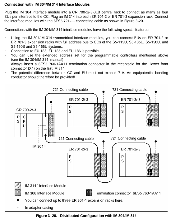
Siemens VVF53. (two-way flange valve) and VXF53. (three-way flange valve) series, belonging to ACVATIX ™ The long stroke valve family is designed specifically for fluid control in industrial and building automation. Its core positioning is control or shut-off valves, compatible with PN 25 pressure rating, and can operate stably in the temperature range of -20… 220 ° C. It covers nominal diameters from DN15 to DN250, meeting different flow and diameter requirements.
Core technical parameters
1. Basic parameter table
Parameter categories, specific specifications, and key explanations
Rated pressure PN 25 (DN15… 50 compatible with PN16) DN65… 250 only compatible with PN25
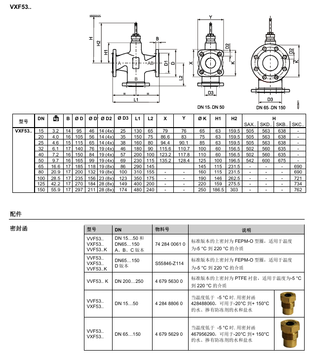
Nominal diameter (DN) 15, 20, 25, 32, 40, 50, 65, 80, 100, 125, 150, 200, 250 DN15… 150 is ductile iron valve body, DN200… 250 is carbon steel valve body
Flow coefficient (kvs) 0.16… 630 m ³/h VVF53. K model (pressure compensation) kvs value optimization, adapted to higher pressure differentials
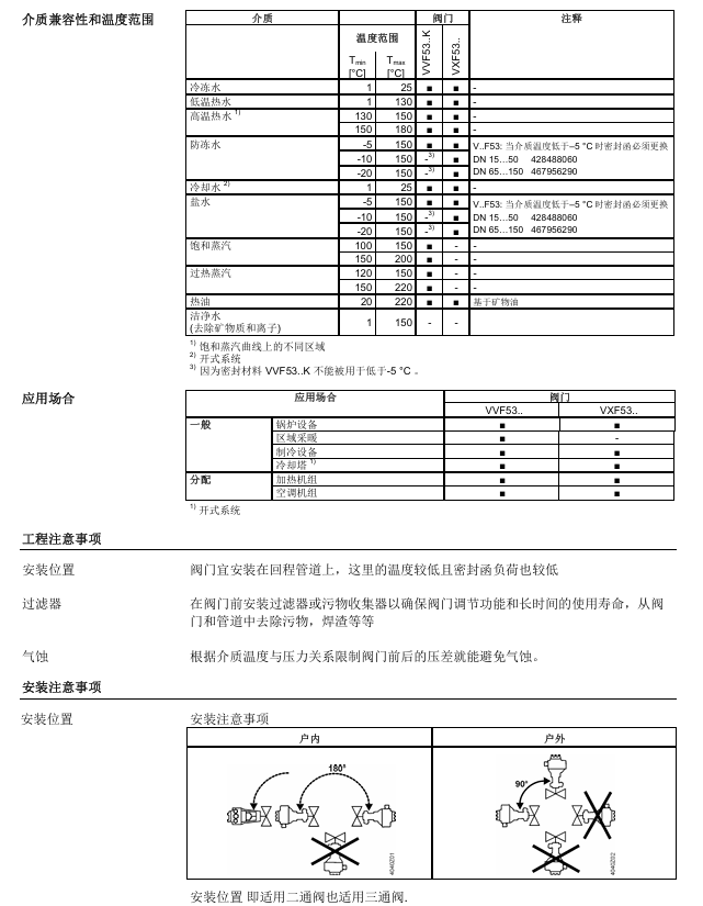
Normal temperature range for medium: -5… 220 ° C; low temperature: -20… 150 ° C (special sealing box needs to be replaced). The maximum temperature for steam medium is 220 ° C, and a low-temperature sealing box is required for antifreeze/saltwater
Rated travel DN ≤ 50:20mm; DN ≥ 65:40mm stroke length matched with actuator driving force (e.g. SAX. compatible with 20mm stroke)
Leakage rate straight through: DN15… 150 is 0… 0.01% kvs (Class IV), DN200… 250 is 0… 0.02% kvs; Bypass: 0.5… 2% KVS complies with EN 60534-4/EN 1349 standards
2. Pressure compensation characteristics (VVF53. K model)
Exclusive design: Using pressure compensation valve core, the same actuator can be used to control flow with greater pressure difference;
Suitable media: liquid and steam (DN65… 150 for closed flow direction, DN200… 250 for open flow direction);
Applicable actuators: Only compatible with electric hydraulic actuators (SKD../SKB../SKC..), not suitable for electric actuators (SAX..).
Executive matching scheme
Executive Parameters and Adaptation Table
Actuator series driving force stroke working voltage control signal operating time (on/off) adapted to valve scenarios
SKD. 1000N 20mm AC24V, AC230V 3-digit, 0… 10V, 4… 20mA, etc. Open for 30s/Close for 10-15 seconds DN ≤ 50 High load scenarios
SKB. 2800N 20mm AC24V, AC230V 3-position, 0… 10V, 4… 20mA, etc. Open for 120s/Close for 10s DN ≥ 65 two-way/three-way valve
SKC. 2800N 40mm AC24V, AC230V 3-position, 0… 10V, 4… 20mA, etc. Open for 120s/Close for 20s DN ≥ 65 large stroke valve
Media compatibility and application scenarios
1. Media adaptation table
Medium type, temperature range (° C), key requirements for valve series adaptation
Frozen water/cooling water 1… 25 VVF53., VXF53. Open systems require attention to impurity filtration
Low/high temperature hot water 1… 180 VVF53., VXF53. 130… 180 ° C is high temperature hot water, and the temperature resistance of the actuator needs to be confirmed
Antifreeze water/saltwater -20… 150 VVF53., VXF53. If the temperature is less than -5 ° C, a special sealing box (DN15… 50:428488060; DN65… 150:467956290) needs to be replaced
Saturated/superheated steam 100… 220 VVF53. (including K-type) VXF53. does not support steam, avoid wet steam (which can easily cause cavitation)
Hot oil 20… 220 VVF53., VXF53. Only suitable for mineral oil hot oil
2. Distribution of application scenarios
Application Fields VVF53. (Two way valve) VXF53. (Three way valve) Core Function
Boiler equipment ✅ ✅ Medium flow control, pressure regulation
Regional heating system ✅ ❌ Hot water delivery cut-off and flow regulation
refrigeration equipment ✅ ✅ Control of chilled water/saltwater circuit
Heating unit/air conditioner ✅ ✅ Switching between hot and cold media, temperature control
Key points for installation and maintenance
1. Installation requirements
Location selection: Priority installation in the return pipeline (low temperature, low sealing load);
Pre installed accessories: A filter or dirt collector must be installed in front of the valve to prevent impurities from jamming the valve core;
Cavitation prevention: Limit the pressure difference before and after the valve according to the temperature pressure curve of the medium to avoid cavitation (special attention should be paid to steam medium);
Flange connection: Following ISO 7005 standard, pipeline flanges, bolts, and gaskets need to be provided on site.
2. Maintenance and Accessories
Routine maintenance: There is no special maintenance requirement for the valve. Before maintenance, the pump should be stopped, the power should be cut off, and the pressure should be released for cooling;
Low temperature accessories: If the medium temperature is less than 0 ° C, a valve stem heating element (ASZ6.6, material number S55845-Z108) needs to be installed;
Sealing letter replacement: When the temperature is below -5 ° C, a dedicated low-temperature sealing letter (DN15… 50:428488060; DN65… 150:467956290) needs to be replaced;
Replacement parts: VXF53. Replace VXF41. Series requires specialized matching parts (such as ALF41B15, compatible with DN15).
Compliance and Standards
Pressure Vessel Directive: Compliant with PED 2014/68/EU, DN65… 125 is classified as Class I (Module A), DN150… 250 is classified as Class II (Module A2);
Basic standards: comply with ISO 7005 (flange), EN 1092 (flange connection), VDI 2173 (valve characteristics), EN 60534-4 (leakage rate);
CE marking: DN65… 150 notified body number 0036, DN200… 250 notified body number 0035, compliance documents can be downloaded from Siemens official website.
6ES5 998-0UF23 is a programmer/operation panel interface module (PG/OP Interface Module) designed by Siemens specifically for SIMATIC S5 series programmable logic controllers (PLCs). As a dedicated communication relay unit between S5 series PLCs and external programming devices (PG) and human-machine interaction devices (OP), its core function is to solve communication protocol adaptation, signal conversion, and link management problems when multiple devices are connected. It is a key hardware component for program debugging, parameter configuration, and on-site operation monitoring in S5 series PLC control systems.
2. Product ownership and historical background
This module belongs to the Siemens SIMATIC S5 series industrial automation product family, which is a mainstream equipment in the industrial control field from the late 20th century to the early 21st century. It is widely used in traditional manufacturing, chemical, metallurgical, power, transportation and other industries. 6ES5 998-0UF23, as a supporting interface module for the S5 series, was designed specifically for the dual device access requirements of “programming equipment+operation panel” in industrial scenarios at that time. It made up for the shortcomings of the early S5 PLC host’s insufficient number of native interfaces and single communication protocol, and is still the core maintenance and operation support component for a large number of in-service S5 series PLC systems today.
3. Core values
Realize stable bidirectional communication between S5 PLC, programmer, and operation panel, ensuring core functions such as program upload and download, online monitoring, and parameter modification.
Support simultaneous access of multiple devices without the need for additional communication expansion modules, simplifying system architecture and reducing hardware configuration costs.
Industrial grade design is suitable for harsh on-site environments, ensuring anti-interference and low latency of communication links, and guaranteeing the stability of continuous production scenarios.
Key technical parameters
1. Hardware specifications
(1) Communication interface
Interface type: 2 RS422 balanced differential interfaces, supporting full duplex communication, strong anti-interference ability, suitable for industrial long-distance transmission.
Interface features: Each interface supports the S5 series dedicated PG/OP communication protocol and is compatible with the hardware interface standards of Siemens S5-PG programmer and S5-OP operation panel.
Transmission rate: Supports multi speed adaptation such as 19.2kbps, 9.6kbps, 4.8kbps, etc. The default speed is 9.6kbps, which can be adjusted through programming configuration.
Transmission distance: Maximum communication distance of 1200 meters (shielded cable), meeting the layout requirements of large-scale industrial field equipment.
(2) Power supply parameters
Power supply method: There is no independent power supply interface, and the working power is obtained from the PLC system through the backplane bus of the S5 PLC rack.
Working voltage: DC 5V ± 5% (provided by PLC backplane bus), power consumption ≤ 1.5W, low-power design does not increase the power supply burden of PLC system.
(3) Physical and installation characteristics
Dimensions: Width 40mm x Height 125mm x Depth 180mm (standard S5 series module size), compatible with standard rack installation of S5 series PLC.
Installation method: rail installation (in accordance with DIN EN 50022 standard rail) or screw fixed installation. The bottom of the module is equipped with a snap on design, which can be quickly mounted on the PLC rack.
Weight: Approximately 280g, lightweight design does not affect the load-bearing balance of the rack.
(4) Environmental adaptability
Working temperature: 0-60 ℃, meeting the high temperature operation requirements of industrial sites.
Storage temperature: -20~85 ℃, suitable for temperature fluctuations in warehouse storage and transportation.
Humidity range: Relative humidity 5%~95% (no condensation), strong moisture resistance.
Electromagnetic compatibility (EMC): Complies with EN 61000-6-2 industrial environment anti-interference standard, anti-static discharge (air discharge ± 8kV, contact discharge ± 4kV), and anti radio frequency interference (80-1000MHz, 10V/m).
2. Communication Protocol and Compatibility
(1) Support agreement
Core protocol: Siemens S5 series dedicated PG/OP communication protocol, supporting program data (PB/FB/SB/DB block) transmission, I/O signal status reading, parameter configuration, fault diagnosis information exchange and other functions.
Protocol features: Based on a connection oriented communication mode, the data transmission belt verification mechanism (parity check/no check optional) ensures the accuracy of data transmission.
(2) Adapting devices
Compatible with PLC models: Fully compatible with S5 series full spectrum PLCs, including mainstream models such as S5-90U, S5-100U, S5-115U (CPU 941/942/943/944), S5-135U, S5-155U, etc.
Compatible Programmer (PG): Siemens S5-PG series programmers (such as PG 605U, PG 635, PG 685), third-party industrial programming devices compatible with S5 protocol.
Adaptation operation panel (OP): Siemens S5-OP series operation panel (such as OP 393, OP 395, OP 396), industrial touch screen with RS422 interface (supporting S5 PG/OP protocol).
Core functions and working principles
1. Detailed explanation of core functions
(1) Programming communication function
Program transmission: Supports uploading control programs (written in STEP 5 language, including logic blocks, data blocks, function blocks, etc.) from the programmer to the S5 PLC host, or downloading programs from the PLC host to the programmer for offline modification.
Online monitoring: Real time transmission of PLC I/O signal status, internal flag bit (F), timer (T), counter (C) data to the programmer, supporting visualization of program running status (such as ladder diagram/statement table online monitoring).
Parameter configuration: PLC system parameters (such as scan cycle, interrupt priority, I/O address allocation) are configured through a programmer, and the configuration data is transmitted to the PLC host through the module and stored.
(2) Communication function of operation panel
Status display: Transmit the running status (RUN/STOP) and fault alarm information (such as I/O faults and program errors) of the PLC to the operation panel for on-site visual prompts.
Command input: Receive manual input commands from the operation panel (such as start/stop commands, parameter settings, manual operation signals), convert them into digital signals recognizable by the PLC, and transmit them to the host.
Data interaction: Real time synchronization of key data between the operation panel and PLC (such as production counting, process parameters, equipment operating time), ensuring real-time human-machine interaction.
(3) Multi device access management
Support simultaneous access of 1 programmer and 1 operation panel, with communication link time-division multiplexing implemented within the module to avoid data conflicts.
Equipped with a communication priority management mechanism, the online debugging instructions of the programmer have a higher priority than the normal operation instructions on the control panel, ensuring that the debugging process is not disturbed.
(4) Fault diagnosis and protection
Communication fault detection: When the communication between the programmer/operation panel and the module is interrupted, the module sends a fault signal to the PLC host through the PLC backplane bus, which can trigger the PLC’s alarm mechanism (such as outputting alarm indicators and storing fault codes).
Overcurrent protection: The interface circuit is equipped with overcurrent protection components to prevent module damage caused by external device short circuits and improve hardware reliability.
2. Working principle
6ES5 998-0UF23 is essentially a protocol conversion and signal relay unit, and its workflow is as follows:
Physical layer: Convert the RS422 differential signal of the programmer/operation panel into a parallel signal recognizable by the S5 PLC backplane bus, and vice versa.
Protocol layer: parses S5 PG/OP protocol instructions (such as program transfer instructions and data read instructions) sent by external devices, converts them into the internal bus instruction format of the PLC host, and implements protocol adaptation.
Data link layer: manages the communication timing of dual interfaces, processes the data transmission requirements of multiple devices accessing simultaneously through time division multiplexing mechanism, and ensures orderly and conflict free data transmission.
Feedback layer: Feedback the response data of the PLC host (such as program transmission confirmation and I/O status data) to the corresponding external device in the original protocol format, completing a two-way communication loop.
Installation and configuration process
1. Installation steps
(1) Hardware installation
Power off preparation: Disconnect the power supply of the S5 PLC system to ensure that there is no risk of electric shock during installation.
Module positioning: Insert the module into the vacant slot of the S5 PLC rack, ensuring that the bus interface at the bottom of the module is fully aligned with the rack backplane, and secure the module with buckles or screws.
Interface connection:
Programmer connection: Use RS422 shielded cable to connect the PG interface of the programmer to the “PG” interface of the module. The shielding layer should be tightened at both ends of the cable to ensure good grounding.
Operation panel connection: Use RS422 shielded cable to connect the communication interface of the operation panel to the “OP” interface of the module, with a cable length not exceeding 1200 meters.
Power on inspection: Connect the power supply of the PLC system. If there is no obvious heating or abnormal noise in the module, and there is no “interface module fault” alarm in the PLC host, it is considered that the installation is normal.
(2) Software configuration
Programmer connection: Start the programmer (such as PG 605U), establish a communication connection with the PLC through STEP 5 software, and select “6ES5 998-0UF23” as the interface module in the communication settings.
Communication parameter configuration: Set the communication rate (default 9.6kbps) and verification method (default no verification) to ensure that the parameters of the programmer, operation panel, and module are consistent.
Device recognition: Through the “device scan” function of the programmer, confirm that the module has been recognized by the PLC host and that the operation panel has successfully connected to the communication link.
2. Wiring specifications
Cable selection: Shielded RS422 cables (such as Siemens 6XV1830-0EH10) must be used, with a core wire cross-sectional area of ≥ 0.5mm ² and a shielding layer coverage rate of ≥ 85% to reduce electromagnetic interference.
Wiring definition: correspondence between module interface pins and external devices (following S5 PG/OP interface standard):
Pin 1: Send positive (TX+)
Pin 2: Send negative (TX -)
Pin 3: Receive positive (RX+)
Pin 4: Receive negative (RX -)
Pin 5: Signal Ground (GND)
Pin 6: Shielding layer ground (SH)
Grounding requirements: The two ends of the cable shielding layer should be grounded with a grounding resistance of ≤ 4 Ω to avoid interference caused by grounding loops.
Typical application scenarios
1. Traditional production line control
Scenario: Automated production lines based on S5-115U PLC (such as automotive parts assembly lines, food packaging lines).
Application: Connect the PG 635 programmer and OP 396 operation panel through 6ES5 998-0UF23 to achieve:
The programmer writes logic programs offline and uploads them to the PLC, monitors the operation status of the production line online, and debugs faults.
The operation panel is used by on-site workers to start/stop the production line, set production parameters (such as packaging speed, counting targets), and view fault alarm information.
2. Industrial machine tool control
Scenario: CNC machine tools and machining centers based on S5-135U PLC.
Application: Connect the module programmer with the machine operation panel to achieve:
Upload the processing logic program to the programmer, modify the tool parameters and motion trajectory parameters.
The operation panel receives manual operation instructions from workers (such as spindle start stop and feed adjustment), and displays real-time machine operation status (such as machining progress and fault codes).
3. Process control scenarios
Scenario: Temperature/pressure control system for chemical reaction kettle and metallurgical furnace based on S5-155U PLC.
Application: Connect the module programmer with the on-site operation panel to achieve:
Configure PID control parameters and set temperature/pressure thresholds for the programmer.
The operation panel displays real-time temperature/pressure data and alarm information, and workers manually intervene in the control process through the panel (such as emergency shutdown and parameter fine-tuning).
Maintenance and troubleshooting
1. Key points of daily maintenance
Regular inspection: Check the module fixation and cable connections for looseness every month, clean the surface dust of the module (wipe with a dry cloth to avoid liquid contact).
Cable maintenance: Check the shielding layer of RS422 cables for damage and oxidation of wiring terminals every quarter, and replace damaged cables in a timely manner.
Environmental monitoring: Ensure that the working environment temperature of the module does not exceed 60 ℃, and avoid contact with the module with moisture, dust, and corrosive gases.
2. Common troubleshooting
(1) Communication interruption
Phenomenon: The programmer/operation panel cannot establish a connection with the PLC or frequently disconnects after connection.
Troubleshooting steps:
Check power supply: Confirm that the PLC system power supply is normal and the module has obtained 5V power supply through the backplane bus.
Check the cable: Replace the RS422 cable, confirm that the wiring definition is correct, and that the shielding layer is well grounded.
Check parameters: Confirm that the communication rate and verification method of the programmer/operation panel are consistent with the module configuration.
Check module status: If the PLC reports “interface module failure”, unplug and reinstall the module. If the fault persists, the module may be damaged and needs to be replaced.
(2) Data transmission error
Phenomenon: Program upload/download failed, or the data displayed on the operation panel is inconsistent with the actual data of the PLC.
Troubleshooting steps:
Check the interference source: Confirm that the distance between the module and strong interference equipment such as frequency converters and motors is ≥ 1 meter, and that the cables are kept away from the power cables (with a distance of ≥ 30cm).
Reduce transmission speed: Reduce communication speed from 19.2kbps to 9.6kbps to improve long-distance transmission stability.
Check PLC status: Confirm that the PLC is in RUN mode and there are no alarms affecting communication such as memory or I/O faults.
(3) Module unresponsive
Phenomenon: After the module is connected, the PLC cannot recognize it, and the programmer/operation panel cannot establish a connection.
Troubleshooting steps:
Check the slot: Replace the vacant slot of the PLC rack and reinstall the module to eliminate the slot fault.
Check module hardware: Observe whether there are burn marks or bent pins on the module. If there are, the module is damaged and needs to be replaced.
Confirm compatibility: Verify whether the module model is compatible with the PLC model (e.g. S5-90U needs to be paired with the corresponding version of 6ES5 998-0UF23).
Siemens SIMATIC S7-200 SMART is a miniature PLC (Programmable Logic Controller) designed specifically for developing markets, with the core goal of balancing performance and cost, providing a cost-effective solution for small automation equipment. Key advantages include:
High speed processing performance: Equipped with Siemens dedicated chips, the basic instruction execution time is as low as 0.15 μ s, which is superior to micro PLCs of the same level and can cope with complex and fast control processes.
Flexible expansion capability: Provides two types of CPUs: standard (expandable I/O modules and signal boards) and compact (integrated I/O, non expandable), adapted to different point requirements.
Convenient communication and operation: Equipped with Ethernet and RS485 dual interfaces as standard, it supports fast program/firmware updates for general Micro SD cards, reducing on-site maintenance difficulty.
Seamless integration solution: Perfectly compatible with Siemens BASIC LINE HMI and SINAMICS V20/V90 drivers, forming a complete micro automation system.
CPU module classification and key parameters
2.1 Classification of CPU Types
Type Series Core Features Representative Models
Standard SR series AC/DC/relay output, supports I/O expansion+signal board SR20, SR30, SR40, SR60
Standard ST series DC/DC/transistor output, supporting high-speed pulse (PWM/PTO) ST20, ST30, ST40, ST60
Compact CR series AC/DC/relay output, non expandable, lower cost CR40, CR60
The number of I/O points in the main body is 12DI/8DO, 18DI/12DO, 24DI/16DO
Maximum I/O capacity (including expansion) 212 points, 222 points, and 40 points (non expandable)
High speed pulse output -3 channels at 100kHz-
High speed counter (single-phase) 4-channel 200kHz 4-channel 200kHz 4-channel 100kHz
Real time clock support (7 days of power failure) support (7 days of power failure) not support
Number of expansion modules: 6, 6, 0
Power type AC 85-264V DC 20.4-28.8V AC 85-264V
Expansion components (signal board and expansion module)
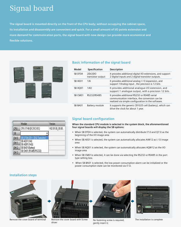
3.1 Signal board (SB): directly installed on the front of the CPU without occupying cabinet space
Model Function Description Key Parameters Order Number (MLFB)
SB DT04 Digital I/O Expansion 2DI/2DO (Transistor Output) 6ES7288-5DT04-0AA0
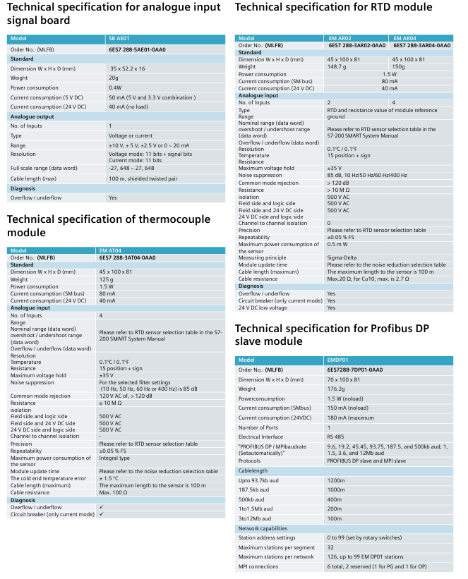
SB AE01 Analog Input Extension 1AI (12 bit accuracy, supporting ± 10V/0-20mA) 6ES7288-5AE01-0AA0
SB AQ01 Analog Output Extension 1AO (12 bit accuracy, supporting ± 10V/0-20mA) 6ES7288-5AQ01-0AA0
SB CM01 communication extension supports RS232/RS485 conversion, with 4 devices connected to 6ES7288-5CM01-0AA0
SB BA01 battery module compatible with CR1025 battery, clock endurance of about 1 year 6ES7288-5BA01-0AA0
3.2 Expansion Module (EM): Used for extensive I/O expansion or special functions
Module type, model, function, key parameters
Digital input EM DI08 8-channel digital input 24V DC, filtering time adjustable from 0.2-12.8ms
Digital output EM DR08 8-channel relay output supports 5-30V DC/5-250V AC, 2A per point
Digital output EM DT08 8-channel transistor output 24V DC, 0.75A per point, surge current 8A
Analog input EM AI04 4-channel analog input with 12 bit accuracy, supporting ± 10V/0-20mA
Analog output EM AQ02 2-channel analog output with 12 bit accuracy, load resistance ≥ 1k Ω (voltage)
Temperature acquisition EM AR04 4-channel RTD input (platinum resistance) accuracy ± 0.1 ℃, cable length ≤ 100m
Temperature acquisition EM AT04 4-channel thermocouple input supports K/J type, cold junction error ± 1.5 ℃
Bus Expansion EM DP01 PROFIBUS DP Slave Module Supports 9.6kbps-12Mbps, Maximum 244 Byte I/O
Core functional characteristics
4.1 Communication Capability
Standard interface:
Ethernet interface: Supports Siemens S7 protocol, can download programs, connect HMI (up to 8 units), communicate with other CPUs, supports 8 active GET/PUT connections+8 passive GET/PUT connections, transmission rate 10/100Mbps (CAT5e shielded wire).
RS485 interface: Supports Modbus RTU, PPI, USS protocols, can connect to third-party devices such as frequency converters and touch screens, with a maximum of 4 HMIs per port.
Expansion interface: Add RS232/RS485 through SB CM01, compatible with barcode scanners, weighing instruments and other devices.
4.2 Motion Control
Hardware foundation: The ST series (transistor output) supports high-speed pulses, with ST20 having 2 channels of 100kHz and ST30/ST40/ST60 having 3 channels of 100kHz.
Core functions:
PWM mode: Fixed pulse period, adjustable duty cycle through program to achieve motor speed regulation and valve opening control.
PTO mode: supports multi-mode positioning (absolute/relative/manual), 4 reference point searches, 32 sets of motion envelopes (16 speed levels per set), and is compatible with stepper/servo motors.
Configuration tool: STEP 7-Micro/WIN SMART motion control wizard, which can quickly generate control instructions and support real-time status monitoring (speed, position, I/O status).
4.3 Convenient operation and maintenance
Micro SD card function (supporting 4-16GB universal cards):
Program transfer: Batch download programs without software, saving time and cost.
Firmware upgrade: Update CPU and expansion module firmware on-site without returning to the factory.
Factory reset: Clear all retained data and quickly reset the device.
Status monitoring: The software supports I/O numerical/waveform monitoring, PID parameter adjustment, and motion control testing, which can verify the correctness of wiring and the rationality of configuration.
Programming software and integration solutions
5.1 STEP 7-Micro/WIN SMART (Programming Software)
Operating environment: Windows XP SP3/Windows 7, installation file<100MB.
Core functions:
Programming language: Supports LAD (ladder diagram), STL (statement table), FBD (function block diagram), and can be freely converted.
Wizard configuration: Provide HSC (high-speed counter) PID、PWM、 Motion control guide, simplifying complex function settings.
Variables and Annotations: Support custom variable names, add annotations to program blocks, networks, and variables to improve readability.
Instruction library: Built in Modbus RTU, USS protocol library, supports password protection to prevent program tampering.
Electromagnetic compatibility: Complies with EN 61000 standard, anti-static (air discharge 8kV), anti radio frequency interference (80-1000MHz, 10V/m).
Installation method: Supports rail installation/screw installation, detachable module terminals for easy wiring and maintenance.
Applicable products: Siemens molded case circuit breakers (MCCBs) and matching fuses, covering three voltage levels of 240V, 480V, and 600V, mainly used in industrial and commercial distribution systems.
Core Value: Addressing the issue of insufficient breaking ratings for branch circuit breakers – By combining CSA certification for main circuit breakers/fuses and branch circuit breakers, it allows branch equipment to break ratings below the system’s available fault current, reducing costs while ensuring safety.
Basic rules and definitions
Series short-circuit rating: The main equipment (line side) and branch equipment (load side) are connected in series, and the combined breaking rating has been tested and certified to meet the requirement of “combined rating ≤ main equipment rating”.
General rating standard: The default breaking rating for individual circuit breakers is 5000A rms symmetrical current, and for individual fuses it is 10000A rms symmetrical current (excluding equipment labeling values).
Load side equipment types: including branch circuit breakers, branch line circuit breakers, built-in main circuit breakers, and remote main circuit breakers, all of which must meet the requirements of series combination.
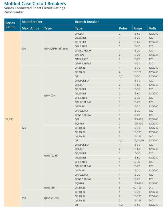
240V level series connection scheme
1. Circuit breaker series combination (240V Breaker)
Covering 4 types of series rated values, the core combination parameters are shown in the following table (excerpted key data):
Series rated value (A) Main circuit breaker model Main circuit breaker maximum current (A) Branch circuit breaker model Branch circuit breaker pole number Branch circuit breaker current range (A) Branch circuit breaker voltage (V)
Using fuses as the main equipment, paired with branch circuit breakers, the core combination is as follows:
Series rated value (A) Main fuse type Main fuse maximum current (A) Branch circuit breaker model Branch circuit breaker pole number Branch circuit breaker current range (A)
6,000 L (1,2,3P) 600 QPH,BQH,BLH 3P 15-100
65,000 T (300V) 200 QAF,BQAF,BAF 1P 15-20
100,000 J,R (2,3P) 600 NJGA,NJJA 3P 200-400
480V series connection scheme
1. Circuit breaker series combination (480V Breaker)
Covering 9 series rated values, core parameters (excerpt):
Series rated value (A) Main equipment type Main equipment model Main equipment maximum current (A) Branch circuit breaker model Branch circuit breaker voltage (V)
Combination of main fuse and branch circuit breaker, core example:
Series rated value (A) Main fuse type Main fuse maximum current (A) Branch circuit breaker model Branch circuit breaker pole number Branch circuit breaker current range (A)
50,000 J (2,3P) 400 ED4 3P 15-100
100,000 T,J,R (3P) 1200 HLXD6-A 3P 450-600
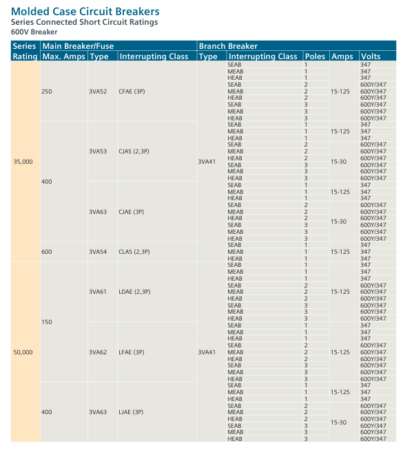
600V series connection scheme
1. Circuit breaker series combination (600V Breaker)
Covering 8 types of series rated values, core parameters (excerpt):
Series rated value (A) Main circuit breaker model Main circuit breaker maximum current (A) Branch circuit breaker model Branch circuit breaker pole number Branch circuit breaker voltage (V) Branch circuit breaker current range (A)
The main fuse is J/R/T type, with a series rated value of 100000A. The branch circuit breakers are JD6 (- A), HJD6 (- A) and other series, with a voltage of 600V and a current range of 200-600A.
Key issue
Question 1: In a 240V distribution system, if a circuit with a series short-circuit rating of 65000A needs to be designed, and the main circuit breaker is selected as HQP series (1P, 70A), what models of branch circuit breakers can be matched? What are the key parameter requirements that need to be met?
Answer: According to the 240V circuit breaker series connection scheme in the document (pages 5-20), when the main circuit breaker is HQP (1P, 70A), the available branch circuit breakers and key parameter requirements are as follows:
Can be matched with branch circuit breaker models: QP, BQ, BL, QPH, BQH, BLH, QT, QPF, BQF, BLF, QE, BE, BLE, etc.
Key parameter requirements:
Number of poles: 1P (corresponding to 1P of the main circuit breaker);
Current range: 15-70 A(QP/BQ/BL/QPH/BQH/BLH)、15-50A(QT)、15-30A(QPF/BQF/BLF/QE/BE/BLE);
Core limitation: The individual breaking rating of branch circuit breakers can be lower than 65000A, but the breaking rating of series combinations must not exceed the rated value of the main circuit breaker HQP, and all combinations must comply with the table entry corresponding to the “65000A series rating” in the document (such as the combination of HQP 1P 70A and QP 1P 15-70A).
Question 2: What is the core design logic of the “series short-circuit rating” in the document? Why is it allowed for the individual breaking rating of branch circuit breakers to be lower than the available fault current? What prerequisites does this design need to meet?
answer:
Core design logic: Utilizing the “pre current limiting effect” of the main circuit breaker/fuse – when a short circuit occurs in the system, the main equipment (line side) triggers the current limiting or breaking action first, reducing the fault current that the branch equipment (load side) needs to withstand, so that the branch equipment can safely break under working conditions lower than its individual breaking rated value, thereby balancing “system safety” and “cost optimization” (without the need to configure high rated equipment for the branch).
The reason for allowing the rated value of the branch to be reduced: The series combination has been tested by CSA certification to verify the suppression effect of the main equipment on fault current, ensuring that the actual fault current borne by the branch equipment is ≤ its breaking capacity. Therefore, there is no need for the branch equipment to separately meet the system’s available fault current requirements.
prerequisite:
Combination compliance: The main branch equipment combination clearly listed in the document must be used, and it is prohibited to replace unverified models;
Rated value limit: The breaking rated value of the series combination is ≤ the breaking rated value of the line side equipment (main circuit breaker/fuse);
Clear identification: The equipment must be labeled with the correct breaking rating, voltage level, and other information, and installed in accordance with the specifications of the power distribution system.
Question 3: What are the differences in the rated range, core equipment model, and application scenarios of the series connection schemes for three voltage levels of 240V, 480V, and 600V?
Answer: The differences in the series connection schemes of the three voltage levels are mainly reflected in the rated value range, equipment selection, and application scenarios. The specific comparison is shown in the following table:
Typical application scenarios include civil building power distribution (such as residential and commercial buildings), small industrial equipment industrial plants (such as motor control and production line power distribution), and large commercial facilities high-voltage industrial scenarios (such as heavy machinery, high-voltage motors, and main power distribution in large factories)
The key difference point supports 1P equipment (single-phase distribution), with the most diverse combination types mainly consisting of 3P equipment (three-phase distribution). The rated value covers the highest voltage range in the medium to high range, and the equipment needs to withstand higher insulation levels. The upper limit of the rated value is lower
The compact operation guide for SIPART PS2 (6DR5…) electric pneumatic positioner covers core contents such as product introduction, safety instructions, installation and mounting, connection, debugging, maintenance, technical parameters, and appendices. It is clear that the positioner is suitable for continuous control of process valves in multiple industries such as chemical, oil and gas, and energy. It emphasizes that the use in hazardous areas must comply with explosion-proof standards (such as ATEX, IECEx), and installation and debugging must follow specific steps (such as automatic/manual initialization). At the same time, detailed technical data (such as working temperature -30~+80 ° C, protection level IP66) and adaptation information for each module (alarm, position feedback, etc.) are provided to ensure safe and compliant operation of the equipment.
Product Usage and Compatibility
Usage: Used in 8 major industries including chemical, oil and gas, energy, food and beverage, papermaking, water supply and drainage, pharmaceuticals, and offshore platforms to achieve continuous control of valves in pneumatic drive processes
Compatibility: Different document versions need to match specific device firmware (FW) and integrated software versions, as shown in the table below:
Communication protocol document version, device firmware requirements, compatible with integrated software (including EDD version)
HART 05/2018 FW: 5.01.00 and above; Device version 6 and above SIMATIC PDM V9.0(EDD:23.00.00+)、AMS Device Manager V12.5(EDD:23.00.00+) wait
PROFIBUS PA 05/2018 FW: 6.00.00 and above SIMATIC PDM V9.0 (EDD: 22.00.00+), SITRANS DTM V4.1 (EDD: 22.00.01+), etc
FOUNDATION Fieldbus 05/2018 FW: 3.00.00 and above; Device version 3 SITRANS DTM V4.1(EDD:3.00.00+)、AMS Device Manager V12.5(EDD:3.00.00+) wait
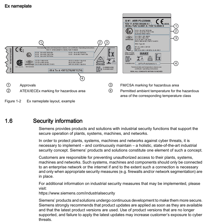
Goods inspection and nameplate
Goods inspection: After receiving the goods, it is necessary to check whether the packaging/items are damaged and verify the consistency between the order and the shipping documents; Prohibit the use of damaged or incomplete equipment (there is a risk of explosion in hazardous areas)
Nameplate information: including key information such as manufacturer, protection level (e.g. IP66), software and hardware versions, explosion-proof identification (e.g. Ex d IIC T6/T4), serial number, etc. The explosion-proof nameplate needs to be additionally labeled with ATEX/IECEx/FM/CSA certification information
Safety instructions (core risk prevention and control)
Warning level system
DANGER: Failure to take preventive measures may result in death or serious personal injury
Warning: Failure to take preventive measures may result in death or serious personal injury
CAUTION: Failure to take preventive measures may result in minor personal injury
NOTICE: Failure to take preventive measures may result in property damage
Requirements for use in hazardous areas
Operator: Must have the qualification to operate equipment in hazardous areas and be familiar with electrical, high-voltage, and hazardous medium safety regulations
Explosion proof requirements: Only use equipment labeled with the corresponding explosion-proof level (such as II 2 G Ex d IIC T6/T4 Gb), and prohibit the use of equipment suitable for non hazardous areas; If the equipment has been used in non hazardous areas, its explosion-proof label must be permanently removed
Special Warning: The pneumatic terminal board of 6DR5. 6 locator is a safety component of explosion-proof shell, and its fixing screws must not be loosened
Other safety regulations
Equipment modification: Only modifications are allowed according to the document instructions. Unauthorized modifications will cancel the warranty and certification
Power requirements: It is necessary to connect a safety isolated Extra Low Voltage (SELV) to avoid voltage flashover; Dangerous area connection equipment must be carried out in a power-off state (except for Ex i version)
Cable requirements: Use cable glands/plugs that meet explosion-proof standards. Unused cable entrances must be sealed, and shielded cables are only allowed to be grounded at one end (when crossing hazardous areas)
Installation and mounting
Basic security prerequisites
Pneumatic actuators have high operating force and must follow their safety instructions; The mounting kit with position detection lever poses a risk of compression, and it is prohibited to insert limbs into the range of motion of the lever
Only use Siemens original accessories/spare parts to avoid the risk of explosion in hazardous areas; Before installation, confirm that there is no visible damage to the equipment and that the sealing gasket is correctly positioned to avoid damage during cover installation
Different mounting methods for actuators
Linear actuator: Use 6DR4004-8V mounting kit, suitable for stroke 3-35mm; for stroke exceeding 35mm, an additional 6DR4004-8L lever needs to be ordered
Angular stroke actuator: VDI/VDE 3845 mounting surface (thickness>4mm with reinforcement) needs to be provided on the actuator side, paired with 6DR4004-8D kit or TGX: 16300-1556 stainless steel coupling
Vibration/acceleration environment treatment
The equipment is equipped with a friction clutch and a gear lock with a transmission ratio selector to cope with strong vibrations/accelerations (such as emergency shut-off valves, steam shock scenarios)
Locking steps: Ensure that the gear lock is in the neutral position → Confirm the gear ratio selector (33 ° or 90 °) → Lock the gear lock with a 4mm screwdriver → Secure the friction clutch (non explosion proof shell version), ensuring that the gear ratio selector is set to the same position as the gear lock (to avoid position detection delay)
Optional module installation
Optional modules for standard/intrinsic safety versions: position feedback module, alarm module, SIA module, mechanical limit switch module, EMC filtering module, NCS sensor, internal NCS module
Optional modules for explosion-proof shell version: only supports position feedback module, alarm module, and internal NCS module; The internal NCS module is used for wear free position detection and is installed in the same slot as the position feedback module
Connection (electrical and pneumatic)
electrical connection
Basic requirement: When the environmental temperature difference exceeds 20 ° C, it should be left to stand for several hours before being powered on (to avoid condensation); When the ambient temperature is ≥ 60 ° C, cables with a temperature resistance of ≥ 80 ° C must be used; The 2-wire version prohibits connecting the voltage source to the current input terminal (I2w, terminals 6/7) and requires the use of a high impedance power supply
PROFIBUS PA: Bus circuit connection terminals 6/7, equipped with safety shutdown input (terminals 81+, 82-)
FOUNDATION Fieldbus: Bus circuit connection terminals 6/7, supporting simulation enable function
M12 connector adaptation: The M12 pins of different modules correspond to different functions, such as the 61+pin 1 (brown) and 62- pin 3 (blue) of the position feedback module 6DR4004-6J/8J
Pneumatic connection
Interface specifications: All are G ¼ or ¼ “NPT internal threads, Y1 is the driving pressure for single/double acting actuators 1, Y2 is the driving pressure for double acting actuators 2
Interface positions for different models:
6DR5. 0/1/2/3: The pneumatic interface is located on the right side of the locator, including Y1, Y2, air source PZ, and exhaust port with muffler
6DR5. 5/6 (Explosion proof enclosure): The pneumatic interface is on the right side, including Y1/Y2 flow restrictor, enclosure ventilation port, and exhaust port
Safe location settings:
When power is off: single acting actuator Y1 releases pressure; Double acting actuator Y1 applies pressure (maximum driving pressure) and Y2 releases pressure; Fail in Place actuator maintains the current pressure of Y1/Y2
Usage of flow restrictor: When the actuator travel time T>1.5s, rotate the Y1/Y2 flow restrictor clockwise to reduce the air output. It is recommended to close it first and then slowly open it. The double acting valve should ensure that the two flow restrictors are set close to each other
Debugging (Commissioning)
Basic safety precautions
Installation and connection must be completed before debugging in hazardous areas, and equipment must be turned off (except for Ex i version); If there may be water in the compressed air pipeline, the purge air selector should be set to “OUT” (then set to “IN” after drainage)
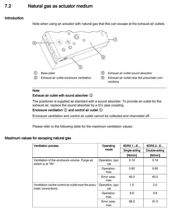
Special requirements for natural gas operation: Only intrinsically safe (Ex ia) equipment can be used; Prohibited from operating in enclosed spaces; Adequate ventilation is required (see technical data for maximum ventilation capacity); Prohibit the use of mechanical limit switch modules; Relieve pressure for at least 2 minutes before maintenance
Initialization type and process
Initialization type:
Automatic initialization: Automatically detect the direction of action, actuator stroke/rotation angle, stroke time, and adapt control parameters, with a time consumption of ≤ 15 minutes
Manual initialization: manually set stroke/rotation angle, and automatically detect other parameters (applicable to PTFE lined valves)
Data replication: Copy the initialization data of the original device when replacing it to avoid process interruption
Core parameters (1-5):
Parameter function applicable to actuators, optional parameter value units
3. YWAY travel range (optional) Linear (WAY/- WAY/ncSLL/- ncLL) OFF, 5, 10, 15, 20 (33 ° short lever); 25, 30, 35 (90 ° short leverage); 40~130 (90 ° long lever) mm
4. InitiatA automatically initializes all NOINI (uninitialized) and Strt (start)-
5. InitiatM manually initializes all NOINI (uninitialized) and Strt (start)-
Automatic initialization steps for linear actuators:
Press and hold the button for 5 seconds to enter configuration mode → Call 2. YAGL to confirm consistency with the transmission ratio selector → Set 3. YWAY (optional) → Call 4. InitiatA and press and hold for 5 seconds to start → Display “FINSH” after completion
Automatic initialization of angular actuator: Similar to linear actuator, default 2. YAGL=90 °, and display the total rotation angle after initialization
Maintenance and upkeep
Basic security requirements
Only authorized personnel from Siemens are authorized to perform repairs; The surface area of equipment in hazardous areas with dust exceeding 5mm needs to be cleaned (to avoid overheating); When cleaning, use a damp cloth or neutral cleaner, and do not use solvents such as acetone (to avoid damaging the plastic/paint surface)
After maintenance, it is necessary to correctly connect the equipment and close the casing to ensure the explosion-proof level; Button lock only allows authorized personnel to cancel (to avoid parameter errors affecting process safety)
Filter cleaning (core maintenance item)
Cleaning methods for different shell materials:
Polycarbonate (6DR5. 0), Aluminum Shell (6DR5. 3), Explosion proof Aluminum Shell (6DR5. 5): Disconnect the air source → Remove the pipeline → Open the cover → Unscrew the 3 screws of the pneumatic terminal board → Remove the filter screen/O-ring → Clean with compressed air → Reinstall in the original order (polycarbonate shell screws are self tapping screws, need to first find the thread counterclockwise before tightening)
Stainless steel shell (6DR5. 2), explosion-proof stainless steel shell (6DR5. 6), single acting aluminum shell (6DR5. 1): Disconnect the air source → remove the pipeline → remove the metal filter → clean and reinstall
Repair and Disposal
Repair: The faulty equipment needs to be sent for repair along with the fault information, and the original equipment serial number needs to be provided when ordering replacement equipment; Prohibition of unauthorized repairs (cancellation of warranty and certification)
Return: Please provide the waybill, return documents, and proof of cleaning. If there is no proof of cleaning, a cleaning fee will be charged
Disposal: Compliant with the WEEE Directive (2012/19/EC), municipal waste disposal is prohibited and must be returned to the supplier or local compliant recycling agency
Technical data
General Parameters
Working conditions: temperature -30~+80 ° C (-40~+80 ° C with Z M40 order code), altitude ≤ 2000m, humidity 0~100%, protection level IP66 (NEMA 4X), anti vibration (2~27Hz: 3.5mm amplitude); 27~300Hz: 98.1m/s ² acceleration
Pneumatic data: Air source pressure of 1.4~7 bar (fault holding double acting 3~7 bar), air quality meets ISO 8573-1 (solid particle Class3, pressure dew point Class3, oil content Class3), valve leakage<6 × 10 ⁻⁴ Nm ³/h, controlled air consumption<3.6 × 10 ⁻² Nm ³/h
Various versions of electrical data (excerpt)
With/without HART: 2-wire system maintaining current ≥ 3.6mA; without HART version (6DR50.) typical load voltage 6.36V (318 Ω), maximum 6.48V (324 Ω); The typical load voltage for the HART version (6DR52.) is 8.4V (420 Ω), with a maximum of 8.8V (440 Ω)
PROFIBUS PA/Foundation Fieldbus: Bus voltage 9~32V (intrinsic safety type 9~24V), current consumption 11.5mA ± 10%, safe shutdown input (terminal 81/82) electrically isolated from the bus circuit
Optional module parameters (excerpt)
Alarm module (6DR4004-6A/8A): 3-channel binary output, intrinsically safe maximum input 30V/100mA/1W, signal high level>2.1mA, low level<1.2mA
Position feedback module (6DR4004-6J/8J): 4-20mA current output (2-wire system), transmission error ≤ 0.3%, temperature impact 0.1%/10K, intrinsic safety type only applicable to T4 temperature level
Mechanical limit switch module (6DR4004-6K/8K): 2 limit contacts, maximum switch current 4A (AC/DC), intrinsic safety maximum voltage 30V, UL certified version (6DR4004-6K) maximum voltage 30V AC/DC, 8K version without UL certification
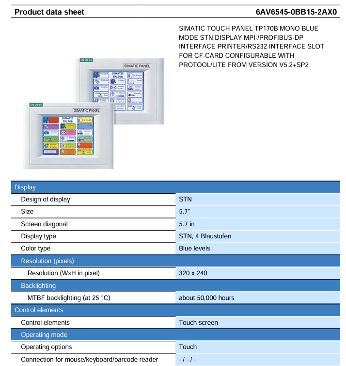
SIMATIC TP170B Touch Screen (Model 6AV6545-0BB15-2AX0) Product Data Sheet, introducing the technical parameters and functional features of this 5.7-inch monochrome STN touch screen: using a 32-bit RISC 66MHz processor, equipped with 768KB user data available memory and 1 CF card slot, supporting multiple communication interfaces such as MPI/PROFIBUS DP (up to 12Mbit/s), front-end protection level IP65, back-end IP20, working temperature 0-50 ℃ (vertical installation); It can be configured through ProTool/Lite V5.2 SP1+or WinCC flexible Compact 2004+, supporting 1000 variables, 100 process screens, 1000 alarm messages, and 100 formulas. It is compatible with multiple brands of controllers such as S7-200/300/400 and TI 505, and is suitable for process monitoring and operation control in industrial automation scenarios.
Hardware core parameters
1. Display and operation unit
Category parameter details
Display screen size 5.7 inches
Display type STN (Super Twisted Column) screen, 4 levels of blue monochrome (Blue levels)
Resolution 320 × 240 pixels (W × H)
Backlight lifespan of approximately 50000 hours (at 25 ℃ environment)
Operation mode: Control element simulation resistive touch screen (touch only operation, no physical buttons)
Input supports numeric input, alphabetical input, hexadecimal input, and does not support simultaneous operation with multiple keys
External device without external mouse/keyboard/barcode reader interface
2. Processor and Memory
Category parameter details
Processor type: 32-bit RISC processor
Main frequency 66MHz
Memory type: Flash memory+RAM
User data available memory 768KB
Expand storage with 1 CF card slot (supports CF card expansion, without SD/USB/hard disk/optical drive)
3. Power supply and power consumption
Category parameter details
Power input voltage type DC (direct current)
Allowable range+18V~+30V DC
Rated voltage 24V DC
Current and power consumption rated current 0.25A
Power consumption 6W
Compatibility between communication interface and controller
Allen Bradley DF1 point-to-point, network (does not support DH485)
Mitsubishi FX/MP4 point-to-point (network not supported)
Telemecanique ADJUST/Uni Track Point to Point, Network
Modicon Modbus point-to-point, network
GE Fanuc SNP point-to-point, network
Software configuration and functional features
1. Configuration tool
Configuration tool version requirements type core usage
ProTool/Lite V5.2 SP1 and above basic configuration tool screen, variable, alarm and other basic function configurations
WinCC flexible Compact 2004 and above advanced configuration tools support task planning and more graphic elements, which need to be ordered separately
2. Core functional parameters
(1) Variable and Image Management
Function category parameter value remarks
The total number of variable management is 1000, including 1000 date and time type variables and 1000 internal variables each
Initial value quantity of 1000 supports variable limit setting and multiplexing
Screen management process with 100 screens supporting PLC selection and configurable startup screens
Each screen contains 50 variables and 2000 text elements, with 100 visible switches per screen
(2) Alarm and Formula Management
Function category parameter value remarks
1000 alarm management operations/fault messages each, supporting 8 process values/messages and 99 confirmation groups
Alarm buffer, circular buffer (n × 128), no sound feedback, supports first/last value display
Formula management: 100 formulas with 32KB integrated Flash storage, expandable
Each formula has 200 data records, with each record containing 200 entries
(3) Graphics and dynamic elements
Function category parameter value remarks
500 graphic element icons, including 50 full screen icons
500 dynamic objects/item, up to 5 per screen, supporting color changes, X/Y movement, and hiding
Trends and charts are plotted horizontally with 8 curves per chart, supporting limit lines
Each chart has 5 bar charts supporting vertical/horizontal directions, including limit lines
3. Safety and maintenance functions
Permission management: 9-level password protection, 10 user groups, passwords can be exported;
The SIMATIC TI545/TI555 controller system manual focuses on the hardware installation, system wiring, program storage, startup, and troubleshooting of TI545-1102 and TI555-1101/1102 CPUs. It specifies that the system supports Series 505 local base (4/8/16 slots) and Series 500 remote base (requires PPX: 500-5114A RBC conversion), and hardware installation must follow the power budget (+5V 55W, -5V 3.75W), grounding specifications (grounding resistance ≤ 0.1 Ω), and anti-interference design (shielded twisted pair, noise suppression); The program can be stored in EEPROM/EPROM (128K/256K bytes), and startup requires completing memory configuration (TI545 maximum 192K bytes, TI555-1102 maximum 1920K bytes) and I/O registration; Troubleshooting relies on LED status indication, auxiliary functions (AUX 10/11/12/20/25/29), and RS-485 cable detection (line resistance 52-87 Ω), while providing Series 500 system upgrade solutions to adapt to discrete/analog control scenarios in industrial automation.
Core characteristics of the system
Control capability: Supports discrete/analog control, can execute relay ladder logic (RLL), PID loop, special function program (SFPGM), supports 256 SF modules;
Remote I/O: 1 RS-485 I/O port, maximum connection to 15 remote bases, distance 3300 feet (1km);
Storage capacity: Supports EEPROM/EPROM non-volatile storage (128K/256K bytes), RAM configurable (TI545 up to 192K bytes, TI555-1102 up to 1920K bytes);
Compatibility: Supports Series 505 local dock and Series 500 remote dock (requires RBC conversion), compatible with old system upgrades.
Hardware Installation Specification
1. Base and module installation
(1) Base type and installation
Key requirements for base model, slot number, installation method
PPX: 505-6504 4 panel installation requires NEMA enclosure with a spacing of ≥ 6 inches (heat dissipation)
PPX: 505-6508 8-panel installation screw hole size as shown in Figure 3-4, torque 2.6-5.22 in lb
PPX: 505-6516 16 16 rack/panel installation compatible with 19 inch rack, depth 7.99 inches
Series 500 6/8/12/14/16 panel installation requires PPX: 500-514A RBC conversion to remote base
(2) CPU installation
Installation location: Series 505 base second slot (adjacent to the power supply);
Battery configuration: 3V rechargeable lithium battery, switch 9 (DIP switch) control enable, backup for 6 months at 0-60 ℃, BATT GOOD light flashes when low battery level;
DIP switch settings:
Switch 1: Port2 mode (left=RS-422, right=RS-485);
Switch 2: Port1 function (left=programming port, right=printer port);
Switch 3-5: Port 1 baud rate (On=1, Off=019200=On/On/On);
Switch 6-8: Port 2 baud rate (same as Port 1);
Switch 9: Battery Enable (Left=On, Right=Off).
(3) Installation of Remote Base Controller (RBC)
Applicable scenarios: Series 505 remote base with PPX: 505-6851A, Series 500 remote base with PPX: 500-5114A;
Installation location: Remote base second slot;
Key settings:
Base number: Thumbwheel set 1-15 (0 is the local base, not available);
Output hold: When the jumper selects communication interruption, output “hold” or “turn off”.
2. Power installation and budget
(1) Power supply model and parameters
Power supply model Input voltage Output power Applicable scenarios
PPX: 505-6660A 110/220V AC (jumper selection)+5V 55W, -5V 3.75W AC power supply scenario
PPX: 505-6663 20-30VDC+5V 55W, -5V 3.75W DC power supply scenario
(2) Power budget calculation
Total power=sum of all modules+5V power+sum of all modules -5V power, must be ≤ 55W (+5V) and 3.75W (-5V);
Typical module power: CPU 4W, RBC 5W, analog module 4-5W, see Appendix B Table B-1 for details.
3. Anti interference and grounding design
Noise suppression:
Noise source: motor, frequency converter, welding machine, with a spacing of ≥ 3 feet;
Suppression measures: Add RC/MOV buffer to inductive load (Figure 2-5/2-6), and use shielded twisted pair cable (12 twisted per foot) for signal;
Grounding specifications:
Grounding resistance ≤ 0.1 Ω, use # 8 copper wire to ground the electrode;
Controller grounding: base → cabinet → grounding electrode, remove the paint surface to ensure conductivity (Figure 2-9/2-10);
Shielded grounding: The input cable is shielded and grounded at the signal source end, and the output cable is shielded and grounded at the base end (single ended grounding).
System cabling and connections
1. Cable selection and wiring
(1) Key cable types
Recommended cable usage, key parameters, maximum length
The complete user guide for SIMATIC 505 series analog I/O modules focuses on four single width modules (input module PPX: 505-6108A/6108B, output module PPX: 505-62088A/6208B), covering the entire process of module technology principles, installation and wiring, calibration and maintenance, and troubleshooting. All modules are compatible with the Series 505 controller, and the input module supports 8-channel ± 5V/± 10V voltage or 0-20mA current signal acquisition (12 bit resolution for version A and 13 bit resolution for version B). The output module synchronously provides 8-channel 0-10V voltage and 0-20mA current signals (12 bit resolution); Installation must follow shielded twisted pair wiring and terminal block wiring specifications. The input module does not require an external power supply, while the output module requires a 20-28VDC user power supply; Calibration needs to be carried out every 6-12 months to ensure measurement and control accuracy in industrial scenarios. At the same time, solutions such as LED status indication and fuse replacement are used to ensure stable operation of equipment, suitable for industrial analog signal processing scenarios such as pressure, temperature, and flow.
Overview of Core Framework and Modules
2.1 Basic Information
Applicable module analog input: PPX: 505-6108A, PPX: 505-6108B; Analog output: PPX: 505-6208A, PPX: 505-6208B
The core positioning is aimed at industrial automation engineers, providing a full process operation guide for module selection, installation, configuration, and maintenance
Certified compliance with UL (Industrial Control Equipment), CSA (Process Control Equipment), ATEX Class I Div.2 (Hazardous Areas), CE (Low Voltage/EMC Directive) and other standards
The supporting documents should be used in conjunction with the SIMATIC 505 System Manual, SIMATIC 500/505 TISOFT Release 6.3 User Manual, and other related documents
2.2 Module Core Positioning and Advantages
Design features: Single width structure, can directly replace dual width analog modules (without modifying the original wiring), saving controller slot space;
Function positioning: As a bridge between the Series 505 controller and industrial field equipment, the input module collects analog signals from sensors (such as temperature transmitters and pressure sensors) and converts them into digital signals. The output module converts the controller’s digital signals into analog signals to drive actuators (such as regulating valves and frequency converters);
Core advantages: Supports multiple signal types, strong anti-interference ability (1500Vrms isolation), easy installation and maintenance, suitable for harsh industrial environments (0-60 ℃ working temperature, 5% -95% non condensing humidity).
Module technology principles and core parameters
3.1 Analog Input Module (PPX: 505-6108A/6108B)
3.1.1 Working principle
The module adopts analog-to-digital conversion (ADC) technology to convert continuously changing voltage/current signals into discrete digital quantities:
PPX: 505-6108A: Adopting dual slope integral conversion method, strong anti-interference ability, suitable for low-speed stable signal acquisition;
PPX: 505-6108B: Adopting the successive approximation conversion method, the conversion speed is faster and the resolution is higher, suitable for high-precision dynamic signal acquisition.
Both convert current signals into voltage signals through internal 250 Ω± 0.1% precision resistors, and then perform ADC conversion.
3.1.2 Key Technical Parameters
Parameter category PPX: 505-6108A PPX: 505-6108B
Number of channels: 8 channels, single ended input: 8 channels, single ended input:
Signal range voltage: ± 5V (default), ± 10V (jumper selection); Current: 0-20mA Same as left
Resolution of 12 bits+sign bit (± 5V range: 1.25mV/step; 0-20mA range: 5 μ A/step) 13 bits+sign bit (± 5V range: 0.625mV/step; 0-20mA range: 2.5 μ A/step
Conversion accuracy (25 ℃) Voltage: ± 0.5% of full scale; Current: ± 0.7% full-scale voltage: ± 0.25% full-scale; Current: ± 0.35% of full scale
Temperature coefficient voltage: 58ppm/℃; Current: 83ppm/℃ Voltage: 50ppm/℃; Current: 80ppm/℃
The maximum conversion time is 330ms (input system delay); Maximum update time 250ms (full channel), maximum sampling repetition time 25ms
Input protection overvoltage: ± 30VDC (clamp diode); Overcurrent: 30mA (optical isolation) same as left
Power requirement: Base only power supply (from controller): maximum 4W, typical 2.5W. Base only power supply: maximum 4W, typical 1.1W
3.1.3 Digital Format and Signal Conversion
The controller only receives 16 bit digital signals, and the module encapsulates the ADC conversion results into 16 bit words:
PPX: 505-6108A: bits 1-12 are valid data, bit 13 is the sign bit (1=negative, 0=positive), bit 14 is the over range bit (1=over range), bits 15-16 are invalid bits (fixed 0);
PPX: 505-6108B: bits 1-13 are valid data, bit 14 is the sign bit, bit 15 is the overrange bit, and bit 16 is the invalid bit (fixed 0);
Over range determination: When the input voltage exceeds ± 5.00125V (± 5V range) or ± 10.0025V (± 10V range), the over range position 1 and the digital quantity exceed ± 32000;
Conversion formula:
Voltage input (± 10V range): Digital quantity (WX)=(input voltage/10V) × 32000;
Current input (0-20mA range): Digital quantity (WX)=(input current/20mA) × 32000.
3.2 Analog Output Module (PPX: 505-6208A/6208B)
3.2.1 Working principle
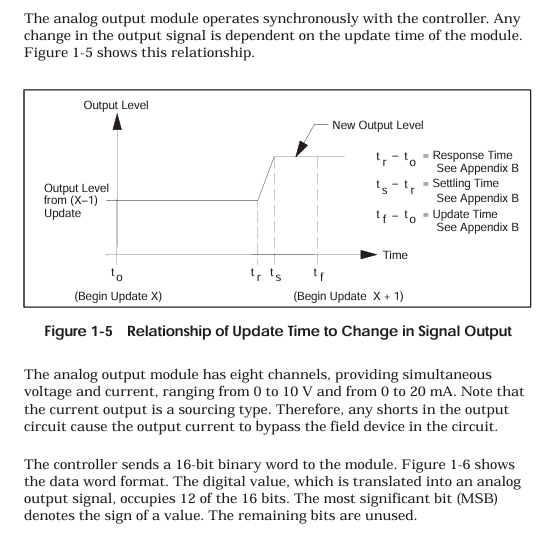
The module receives a 16 bit digital signal from the controller and converts it into a continuous analog signal through digital to analog conversion (DAC) technology. The voltage and current outputs are synchronized (the same channel can output two types of signals simultaneously without switching):
The current output is designed as a source type, and in the event of a short circuit, the current will bypass the on-site equipment. It is necessary to avoid short circuits in the output circuit;
If the digital sign bit (bit 1) is 1 (negative value), the module does not update the output and maintains the previous positive value output.
3.2.2 Key Technical Parameters
Parameter category PPX: 505-6208A PPX: 505-6208B
Number of channels: 8 channels, single ended output: 8 channels, single ended output:
Signal range voltage: 0-10VDC; Current: 0-20mA (source type) same as left
Resolution 12 bits (voltage: 2.5mV/step; Current: 5 μ A/step) Same as left
Conversion accuracy (25 ℃) Voltage: ± 0.5% of full scale; Current: ± 0.5% full range same as left
Full temperature range precision voltage: ± 1.45% of full range; Current: ± 1.83% full range same as left
Temperature coefficient voltage: 136ppm/℃; Current: 204ppm/℃ Voltage: 50ppm/℃; Current: 100ppm/℃
Response characteristic response time: 27ms (minimum) -54ms (maximum); Stability time: Voltage 0.2ms, Current 2.0ms Response time: Maximum 10ms Stability time: Same as left
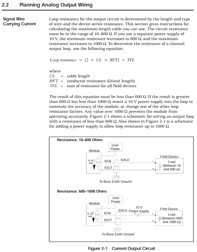
Load requirement voltage: ≥ 5000 Ω, maximum capacitance 0.01 μ F; Current: 10-600 Ω (over 600 Ω requires 10V power supply, maximum 1000 Ω) Same as left
Power demand base power supply: maximum 2W (typical 1.0W); User Power Supply: 20-28VDC, 0.5A (Ripple ≤± 0.4VDC, UL Class 2) Same as Left
3.2.3 Digital Format and Signal Conversion
The controller outputs a 16 bit digital quantity: bits 1-12 are valid data, bits 13-16 are invalid bits (fixed to 0);
Conversion formula:
Voltage output: Digital quantity (WY)=(target voltage/10V) × 32000;
Current output: Digital quantity (WY)=(target current/20mA) × 32000.
Temperature and voltage resistance: The wire has a temperature resistance of ≥ 75 ℃ and a rated voltage of ≥ 300V, meeting the insulation requirements of industrial environments;
Anti interference measures:
Separate the wiring of signal cables and power cables (such as motor power lines) to avoid parallel laying, and form a 90 ° angle when crossing;
Avoid laying cables on vibrating surfaces, do not bend them into sharp angles, and use cable trays for standardized routing;
Shielding layer grounding: The shielding layer of the input cable is grounded at the signal source end, and the shielding layer of the output cable is grounded at the controller base end. It is strictly prohibited to ground both ends at the same time (to prevent noise caused by ground circulation).
4.1.2 Output module circuit calculation
Current circuit resistance: circuit cable equipment (L is the cable length, cable is the unit length resistance, equipment is the on-site equipment resistance); When the circuit is between 10-600 Ω, connect it directly; When the circuit is between 600-1000 Ω, a 10V DC power supply needs to be connected in series in the circuit; When the circuit is greater than 1000 Ω, it is necessary to replace the thick wire diameter cable or shorten the wiring distance, otherwise the output accuracy will decrease.
Fixed error of voltage circuit: The error equipment cables must ensure that the error is within the allowable range.
4.2 Terminal block wiring
4.2.1 Terminal block types and wiring steps
Terminal block model:
Standard configuration: PPX: 2587705-8006;
Optional: PPX: 2587705-8002 (wiring method consistent with standard, can replace old terminal blocks of double width modules);
Wiring steps:
Strip wire 0.25 inches (1.0cm), optional installation of fork/ring terminal blocks (Amp 321462/327891, compatible with # 4 studs);
Connect the wires according to the pin diagram (Figure 2-4), first connect the D terminal, then connect the C, B, and A terminals in sequence, and tighten the screws to ensure good contact;
After the wiring is completed, check the terminal definition to avoid misconnection (such as the “Return” terminal of the input module cannot be suspended, and the “24V common” output module needs to be reliably grounded).
4.2.2 Input module wiring differences
Key points to note for input type wiring method
Voltage input (± 5V/± 10V) signal+connected to voltage input terminal (such as channel 1 connected to A2 “V1 in”), signal – connected to return terminal (A3 “Return 1”) does not need to be short circuited, ensuring that the internal resistance of the signal source is ≤ 1k Ω to avoid signal attenuation
Current input (0-20mA): First, short-circuit the current input terminal (A1 “I1 in”) to the voltage input terminal (A2 “V1 in”). Connect the signal+to A1 and the signal – to A3. The short circuit should be directly connected with a wire and should not pass through high resistance components to ensure that the current flows through the internal 250 Ω resistor
4.2.3 Typical wiring scenarios
2-wire transmitter wiring (input module): transmitter+connected to input module current input terminal, transmitter – connected to return terminal, module provides power to transmitter through internal circuit;
4-wire transmitter wiring (input module): The transmitter is independently powered, with signal+connected to the current input terminal and signal – connected to the return terminal;
Output module wiring (4-channel example): Each channel simultaneously outputs voltage (such as A2 “V1 out”) and current (A1 “I1 out”), which are connected to the corresponding actuators. The common terminal (Return) is grounded uniformly.
4.3 Module Installation and I/O Configuration
4.3.1 Module installation steps
Power off operation: Before installation, turn off the controller and all external power sources to avoid electric shock or component damage;
Slot selection: Insert the module into the idle single width I/O slot of the Series 505 controller, avoiding proximity to high-energy switch modules or EMI sources (such as frequency converters);
Fixed module: Tighten the module panel with screws and control the torque at 2.6-4.12 in lb (0.3-0.6N · m) to avoid damaging the module or base due to over tightening;
Static protection: Do not touch the module circuit board during installation, and wear an anti-static wristband if necessary.
4.3.2 I/O Configuration Process
Configuration tool: Use SIMATIC 500/505 TISOFT Release 6.3 software to connect the controller through programming devices;
Module registration: Select the base number and slot number in the “I/O Module Definition Table”, configure the module type and I/O parameters (Table 2-1):
|Module model | WX (number of input words) | WY (number of output words)|
| PPX:505–6108A | 08 | 00 |
| PPX:505–6108B | 08 | 00 |
| PPX:505–6208A | 00 | 08 |
| PPX:505–6208B | 00 | 08 |
Address allocation: The system automatically assigns I/O addresses (such as the input module address for slot 1 starting from WX0001), which are downloaded to the controller after configuration is complete;
Verify configuration: After powering on, observe the “Module Good LED” of the module. If the LED lights up, it indicates that the configuration is successful and the module has no faults.
Calibration and maintenance process
5.1 Basic Requirements for Calibration
5.1.1 Calibration cycle and conditions
Calibration cycle: It is recommended to calibrate every 6-12 months; If the module is used in high temperature and vibration environments for a long time, or if the measurement accuracy exceeds the tolerance, it needs to be calibrated immediately;
Environmental conditions: The calibration environment temperature is 25 ℃± 2 ℃, with no vibration or electromagnetic interference. The module reaches working temperature after being powered on for 30 minutes;
Tool preparation:
Calibration power supply: DC voltage source with an accuracy of ≥ 0.01% (used for input module calibration);
Measurement tool: a multimeter with an accuracy of ≥ 0.1% (for voltage/current measurement);
Power off preparation: Turn off the controller power, disconnect the module field wiring. If using Euro extender card, remove the module first, insert the card, and then install the module onto the card;
Range selection: Select the calibration voltage range (± 5V or ± 10V) through the jumper on the module circuit board;
Power on preheating: Turn on the controller power and wait for 30 minutes for the module to reach operating temperature;
Device connection: Connect programming devices and controllers to ensure that module input data can be read; Connect the calibration voltage source to all input channels of the module;
Full range calibration (positive direction):
Input+5V (± 5V range) or+10V (± 10V range) to all channels;
Adjust the calibration potentiometer on the module circuit board with a non-metallic screwdriver until the programming device displays an average of+32000 for all channel numbers;
Full range calibration (negative direction):
Input -5V (± 5V range) or -10V (± 10V range) to all channels;
Adjust the potentiometer until the average digital value of all channels is -32000;
Accuracy verification: Enter+5V/+10V again to verify the numerical deviation:
PPX: 505-6108A: allowable deviation of ± 129/± 128;
PPX: 505-6108B: allowable deviation of ± 81/± 80;
Restore wiring: After calibration is complete, power off, remove the calibration equipment, restore on-site wiring and module installation positions, and reconfigure I/O addresses.
5.3 Calibration steps for output module (PPX: 505-6208A/6208B)
Power outage preparation: Turn off the controller and user power, disconnect the module load from the on-site wiring, and retain the user power wiring;
Load connection: Connect calibration loads to all output channels of the module (voltage channel connected to a 5.1k Ω resistor, current channel connected to a 100 Ω resistor);
Power on preheating: Turn on the controller and user power, wait for 30 minutes for the module to reach operating temperature;
Device connection: Connect programming devices and controllers to ensure that digital data can be written to the module;
Full range output: Write a digital quantity of 32000 to all channels (corresponding to 10V/20mA full range output);
Reference channel selection: Measure the current output values of all channels, calculate the average value, and select the channel with the output value closest to the average value as the reference;
Current calibration: Use a non-metallic screwdriver to adjust the calibration potentiometer so that the reference channel current output is 20.000mA (25 ℃);
Accuracy verification:
Voltage output: All channels must be 10.000V ± 50mV;
Current output: All channels must be 20.00mA ± 0.1mA;
If the deviation exceeds the tolerance, repeat steps 6-8;
Restore wiring: After calibration is completed, power off, remove the calibration load, and restore on-site wiring and module configuration.
5.4 Daily maintenance and troubleshooting
5.4.1 Key points of daily maintenance
Cleaning module: Clean the module panel and terminal block with a dry soft cloth every 3 months to avoid dust accumulation;
Wiring inspection: Check the tightening of terminal block screws every 6 months to prevent loose wiring caused by vibration;
Power inspection: Regularly check the user power supply (20-28VDC) of the output module to ensure that the ripple is ≤ ± 0.4VDC;
Fuse maintenance: When the output module fuse (0.5A fast melting, model PPX: 2587679-8009) burns out, it is necessary to first investigate the cause of overvoltage/overcurrent before replacing the fuse.
5.4.2 Common troubleshooting
Possible causes of malfunction, troubleshooting steps, and solutions
Module Good LED not lit (input module) Base power failure, module self diagnosis failure 1. Measure whether the base power supply voltage is normal; 2. Check if the module is correctly inserted into the slot; 3. Disconnect all wiring and reinstall. 1. Repair the power supply of the base; 2. Re plug and unplug the module; 3. Module self diagnosis failure requires return for repair
Module Good LED not lit (output module) Base power failure, user power failure, blown fuse, self diagnosis failure. 1. Measure the base and user power supply; 2. Check the status of the fuse; 3. Check if the module wiring is short circuited. 1. Repair the power supply; 2. Replace the fuse; 3. After eliminating the short circuit, power on again; 4. Self diagnosis failure requires return for repair
Input module reading error, wiring error, signal noise, calibration deviation, signal source out of range. 1. Check the wiring by referring to the pin diagram; 2. Check if the grounding of the shielding layer is correct; 3. Verify whether the output of the signal source is within ± 5V/± 10V or 0-20mA; 4. Recalibrate module 1. Correct wiring; 2. Optimize shielding and wiring; 3. Adjust the signal source to the effective range; 4. Complete calibration
The output module outputs abnormal loads beyond the range, digital input errors, calibration deviations, and unstable user power supply. 1. Measure whether the load resistance/capacitance meets the requirements; 2. Check if the digital output of the controller is correct; 3. Recalibrate the module; 4. Measure the user’s power ripple. 1. Replace the load that meets the requirements; 2. Repair the digital output of the controller; 3. Complete calibration; 4. Replace the stable power supply
PLC reports non fatal module configuration error, module and controller communication failure. 1. Check the I/O configuration parameters (WX/WAY quantity); 2. Check if the module is in good contact with the base; 3. Restart the controller. 1. Correct the configuration parameters; 2. Re plug and unplug the module; 3. If the error persists after restarting, it needs to be returned for repair
Environmental and Safety Parameters (Appendix B)
6.1 Environmental adaptation parameters
Parameter indicators
Working temperature 0-60 ℃ (32-140 ℉)
Storage temperature -40-70 ℃ (-40-158 ℉)
Relative humidity 5% -95% (non condensing)
Vibration resistance sinusoidal vibration: 10-57Hz, 0.15mm peak to peak value; Random vibration: 57-150Hz, 1.0g
Impact resistance meets the IEC 68-2-27 Test Ea standard
Hazardous area use: Complies with ATEX Class I Div.2 standards and can be used in flammable dust environments (must meet dust explosion prevention requirements);
Wiring safety: The rated voltage of signal cables should be ≥ 300V, avoid mixing with power cables, and prevent insulation breakdown.
The Siemens S7-1200/1500 Controller TIA Portal Programming Guide (V1.6 version) focuses on optimizing programming and covers the core innovations of the S7-1200/1500, such as optimization blocks, new data types VNet, direct machine code compilation, general programming specifications (block structure, symbol addressing, memory management), hardware independent programming methods, STEP 7 Safety programming points, and visual automatic generation solutions. It explicitly recommends using optimization blocks instead of non optimization blocks, symbol addressing instead of absolute addressing, and global data blocks instead of bit memory. At the same time, it provides a large number of performance optimization techniques (such as avoiding deep call hierarchy and using loop instructions reasonably), aiming to help users achieve standardized, efficient, and reusable automation program development.
S7-1200/1500 Core Innovation
1. Programming languages and compilation optimization
Language support differences:
Programming language S7-1200 S7-1500
Ladder diagram (LAD) ✅ ✅
Function Block Diagram (FBD) ✅ ✅
Structured Control Language (SCL) ✅ ✅
Statement Table (STL) ❌ ✅
Sequential Function Graph ❌ ✅
Compilation method: S7-1200/1500 generates machine code directly for all languages, without the intermediate step of “LAD/FBD → STL → machine code” for S7-300/400, ensuring consistent performance for all languages.
2. Optimize block technology (core innovation)
Optimized block vs non optimized block:
Feature optimization block (recommended) Non optimization block (only compatible)
Data storage is automatically sorted by data type, stored in declared order without gaps, and may have gaps
The addressing method can be either symbolic addressing or absolute addressing
Retention settings: A single label can be set to maintain the entire block or not to maintain it
Download feature supports uninitialized download (RUN mode update) not supported
Fast access speed (processor optimized storage) slow
Setting method: By default, “Optimize Block Access” is enabled for new blocks, which can be batch modified in the “Program Block” list; The optimization properties of instance DB inherit from the associated FB.
3. New data types
Core new type:
Data Type Applicable Controller Purpose Key Features
VARIANT S7-1500; S7-1200 (FW4.1+) dynamic pointer with type detection, replacing the ANY pointer, supporting symbol access
Date_Time_Long (DTL) both support timestamp storage containing year/month/day/nanosecond, with symbol accessible sub fields (such as DTL. Hour)
Both LReal and LReal support high-precision floating-point numbers of 64 bits and 15 decimal places, making them suitable for precise calculations
LTime only has a long-term storage range of ± 106751 days for S7-1500 and supports nanosecond level accuracy
WSRING only supports S7-1500 Unicode strings for multiple languages (such as Chinese and Latin), with a maximum of 16382 characters
4. Key instruction upgrade
MOVE series instructions:
Advantages of Instruction Usage
MOVE supports single value copying and complete copying of structures/arrays
MOVE_SLK array partial copy specifies the starting index and quantity, efficiently processing the array
MOVE_SLK_VARIANT Dynamic Type Copy Run Time Detect Data Types, Supports PLC Data Types/Arrays
The serialize/deserialize structure and byte array conversion are used for communication frame packaging/unpacking, supporting VNet input
Other instructions:
TypeOf(): detects the data type pointed to by VNet on the label (SCL only);
RUNTIME: measures program/block running time, supports performance optimization;
Multi assignment (V14+): such as # a:=# b:=# c:=0; Simplify initialization.
Universal Programming Specification
1. Program block structure
Core block type:
Key features of block type functionality
Organizational block (OB) operating system call, management program execution including loop OB (OB1), interrupt OB (OB40 hardware interrupt), etc; S7-1200 up to 100 cycles/start OB, S7-1500 supports clock interrupt OB
Function (FC) has no state block and no independent storage temporary label. Only the current call is valid, and data needs to be passed through parameters; Support direct participation of return values in SCL formulas
Function block (FB) has a status block that requires the instance DB static label to maintain its value; The instance DB structure is defined by FB and cannot be modified separately
Data Block (DB) stores data in a global DB for all blocks to access; Instance DB is only associated with FB usage
Block Reuse Techniques:
Multiple instances: FB calls other FBs to store data in their own instance DB, reducing the number of instance DBs;
Typeization block: Store FB/FC/PLC data types in the global library, supporting cross project reuse and batch updates.
2. Memory management
Memory type and access speed (from fast to slow):
Optimize the temporary labels, FC/FB parameters, and non persistent static labels of the block;
Optimize the retention labels of blocks and optimize the global database;
Non optimized blocks;
Array access for runtime calculation index (such as # Array [# i]);
Indirect memory access (such as pointer operations);
Data replication between optimized and non optimized blocks.
Key recommendations:
Replace bit memory with global DB (M-zone): The size of M-zone varies depending on the controller, while global DB is more flexible and supports optimized storage;
Use temporary tag caching for frequently accessed I/O tags to reduce the number of I/O accesses;
Retention setting: Only the necessary labels need to be set to hold (such as process parameters) to reduce the cost of saving power-off data.
3. Addressing method
Symbol addressing (mandatory recommendation):
Advantages: The tag name is descriptive (such as # Motor1_Run) and automatically updates when the address changes, reducing errors;
Operation: Simply enter the symbol name in the instruction input box, right-click on “Define Label” to quickly create it.
Indirect access scheme:
Indirect array access: Replace pointers with # Array [# Index], such as # Temp:=# MotorSpeed [# i];;
Slice access: Directly access the bits/bytes of Byte/Word/DWord, such as # WordVar.% X0 (bits), # DWordVar.% W1 (words).
4. Performance optimization techniques
Disable the ENO evaluation (LAD/FBD) of blocks to reduce runtime detection;
Avoid deep level calling (≤ 8 layers), otherwise TIA Portal will compile alarms and increase protection code overhead;
FOR loop: Do not manipulate the loop counter (compiler optimized times), use EXIT to interrupt the loop;
Reduce unnecessary IF instructions, such as # Motor:=# On1 AND # On2; Replace IF # On1 AND # On2 THEN # Motor:=TRUE; ELSE #Motor:=FALSE; END_IF;。
Hardware independent programming
1. Data type compatibility
Only use EN 61131-3 standard data types (such as INT/DINT/REAL/BOOL), avoiding S7-300/400 specific types (such as S5TIME);
The timer/counter of S7-1200/1500 uses IEC standard blocks (such as TON/CUTU) and is integrated through multiple instances to avoid absolute addresses (such as T37).
2. Clock signal replacement
Do not use hardware clock memory (such as M0.5), use programming clock generation block instead:
Example: SCL writes FB, sets the frequency through the # Frequency parameter, # Q outputs pulses, and # Countdown outputs the remaining time;
Advantage: The clock frequency can be flexibly adjusted without relying on hardware configuration.
STEP 7 Safety Programming
1. Core components
F operation group: the execution unit of safety programs, including 1 fault safety OB and 1 main safety block, with a maximum of 2 created;
F-signature: a unique identifier for each F-component (F-I/O, F-block) used to detect configuration/programming changes;
Security Management Editor: Manage F run groups, F signatures, access permissions, and set security program passwords.
2. Key specifications
Data exchange: Standard programs and security programs only interact through two standard DBs, avoiding direct access to the security DB;
Performance optimization:
Avoid using TP/TON/TOF instructions (add protection code);
Disable the JMP/Label structure (resulting in additional system protection blocks);
Loop call hierarchy ≤ 8 layers;
Test restriction: The security program can only force testing when the security mode is disabled, with a maximum of 5 F-I/O forced at a time.
Visual automatic generation (SiVArc)
1. Basic requirements
Tools: TIA Portal V14++SiVArc Options Package;
Prerequisite: The program is modularized (such as motor control FB, conveyor belt FB), and the visualization library includes standard image templates.
2. Control mode
Network comment: Add a tag (such as “SiVArc: Generate=True”) when calling the network on FB. The SiVArc rule triggers generation through Contains (Block. NetworkComment, “Generate=True”);
SiVArc variable: Define a variable in the “Plugin” label of the block (such as Location=”Bottling_Test”), and the rule filters the generated range based on the variable value.
The PFT6 series is a strain gauge weighing sensor designed for harsh industrial environments. Its core advantages are high precision, high protection, and strong anti-interference ability. It is suitable for scenarios with strict requirements for weighing accuracy, such as batching systems and trade settlement belt scales. The range covers 10kg-5000kg and can meet the needs of industrial weighing from light to medium.
Product principle and core features
1. Measurement principle
Based on the effect of resistance strain gauges, the core structure consists of a metal elastomer and resistance strain gauges attached to the elastomer
When the sensor is subjected to a load, the metal elastomer undergoes slight deformation;
Strain gauges undergo resistance changes with the deformation of the elastic body (stretching → increasing resistance, compression → decreasing resistance);
Convert the resistance change into a voltage signal (rated output 2mV/V) through a Wheatstone bridge, and transmit it to the weighing instrument for data processing.
2. Core Features
High precision level: C3 level in accordance with OIML R60 standard (suitable for medium to high precision weighing, division value ≤ 3000), ensuring the accuracy of trade settlement and industrial batching;
High protection performance: The conventional model has a protection level of IP67 (dustproof, anti short-term immersion), and the special customized model can reach IP68 (no damage after soaking in 1m underwater for 24 hours), suitable for harsh industrial environments such as dust and humidity;
Wide temperature adaptability: Temperature compensation range of * * -10 ℃~+40 ℃ (ensuring stable accuracy within this range), working temperature range of -30 ℃~+60 ℃ * *, suitable for high and low temperature industrial scenarios;
Anti interference capability: The single ended grounding design of the cable shielding layer reduces electromagnetic interference (EMC) and is suitable for industrial strong electromagnetic environments;
Overload protection: Safe overload capacity of 150% rated load (R.C.), ultimate overload capacity of 300% R.C., to avoid permanent damage caused by accidental overload.
Key technical parameters
1. Range and accuracy parameters
Range (R.C.) Accuracy level Nonlinear (≤±% R.O.) Lag (≤±% R.O.) Repeatability (≤±% R.O.) Sensitivity Temperature drift (≤±% R.O./℃)
Environmental inspection: Confirm that the installation environment temperature and humidity meet the parameter requirements, there are no corrosive gases or strong magnetic fields (if additional protection is required);
Load confirmation: Ensure that the actual weighing load is within the range of the sensor (avoid long-term close to 150% R.C. safe overload);
Installation plane: The support surface should be flat (flatness error ≤ 0.1mm/m), sturdy, and avoid affecting measurement accuracy due to deformation of the support surface;
Alignment requirements:
When installed vertically, the load should be applied along the axis direction of the sensor, and tilting is prohibited (deviation ≤ 0.5 °);
When installing horizontally (such as a belt scale), the sensor needs to be accurately aligned with the weighing frame to avoid lateral forces;
Load limit: Strictly control lateral force and torque to ≤ 10% R.C., and install guiding devices (such as locating pins) if necessary;
Fixed specifications:
Range (R.C.) Fixed thread specification Recommended torque (Nm) Prohibited behavior
Excessive tightening of M6 8 from 10kg to 50kg (to avoid deformation of the elastic body)
100kg-200kg M8 12, use a hammer to strike the sensor (damaged strain gauge)
500kg-1000kg M12 18 sensor in direct rigid contact with load (without buffering)
2000kg-5000kg M16 20 adjust the load direction after installation (generate lateral force)
3. Electrical connection specifications
Wiring method: Adopting a 4-wire system (red: excitation+, black: excitation -, green: signal+, white: signal -), some models support a 6-wire system (including compensation lines to improve long-distance transmission accuracy);
Cable requirements:
Use shielded cables (recommended cross-sectional area 0.25mm ² -0.5mm ²), with a cable length of ≤ 30m (if exceeding, a 6-wire system or signal amplifier is required);
Single end grounding of cable shielding layer (only grounded at the weighing instrument end to avoid the formation of grounding circulation);
Joint protection: IP67 waterproof joint is used, and the sealing nut needs to be tightened tightly after connection to prevent liquid infiltration;
Insulation requirement: Before wiring, a multimeter should be used to check the insulation resistance of the sensor (≥ 5000M Ω) to avoid signal interference caused by poor insulation.
Calibration and maintenance process
1. Calibration specifications
Calibration standard: Must comply with OIML R60 C3 level requirements, with calibration equipment accuracy ≥ 1/3 C3 level (such as standard weights, SIWAREX calibration tools);
Calibration conditions:
After the installation of the sensor is completed, let it stand for 24 hours (to ensure the release of elastic stress);
The ambient temperature remains stable at * * -10 ℃~+40 ℃ * * (within the temperature compensation range);
No vibration or airflow interference;
Calibration steps:
No load calibration: Ensure that the sensor is unloaded, perform “zero calibration” through the weighing instrument, and clear zero drift;
Loading calibration: Load standard weights in the order of 25% R.C., 50% R.C., 75% R.C., and 100% R.C., and record the instrument display value;
Error correction: If the displayed value deviates from the standard weight by more than ± 0.02% R.O., adjust the sensitivity through instrument parameters and repeat loading until the error is compliant;
Calibration records: Save calibration data (date, equipment, personnel, error values), and calibration certificates must comply with NIST traceability requirements.
2. Daily maintenance
Cleaning requirements: Clean the sensor surface every 3 months (using a dry soft cloth and avoiding the use of corrosive cleaning agents) to prevent dust and liquid accumulation from affecting the protective performance;
Status check:
Monthly inspection of mechanical connections (whether threads are loose and joints are sealed);
Calibration cycle: Under normal usage scenarios, calibration should be conducted every 12 months. If used for trade settlement or harsh environments (such as vibration and high temperature), it should be shortened to 6 months;
Fault handling: When weighing data drift and accuracy decrease are found, priority should be given to checking the installation status (whether there is lateral force or deformation of the support surface), and then recalibration should be carried out. If there are still abnormalities, Siemens maintenance should be contacted.
Sensors are precision equipment and should not be disassembled, knocked or welded, as this may cause permanent damage;
Explosion proof scenarios require the use of ATEX certified models, and conventional models are prohibited from being used in explosion-proof areas (such as chemical workshops).
2. Compliance certification
Compliant with EN 61298-2 (Safety Requirements for Industrial Weighing Equipment) and IEC 61298-2 (International Standard);
Having CE certification (EU market access) and optional ATEX certification (for use in explosion-proof areas);
The weighing accuracy meets OIML R60 C3 level and can be used in trade settlement scenarios (with compliance instruments required).
Application scenarios and adaptive instruments
1. Typical application scenarios
Application type, specific scenario, recommended range, protection level requirements
Belt scale weighing industrial belt conveyor (such as coal and ore transportation) 500kg-5000kg IP67
Weighing of chemical raw material tanks and food ingredient hoppers 100kg-5000kg IP67/IP68 (wet)
Automatic packaging machine for packaging equipment (such as flour and feed packaging) 10kg-200kg IP67
Industrial batching system multi-component mixed batching (such as concrete, paint) 50kg-1000kg IP67