Call us 24/7uaedcs@163.com
Welcome to the official website of CNIACS Automation Technology Co., Ltd!
Call us 24/7uaedcs@163.com

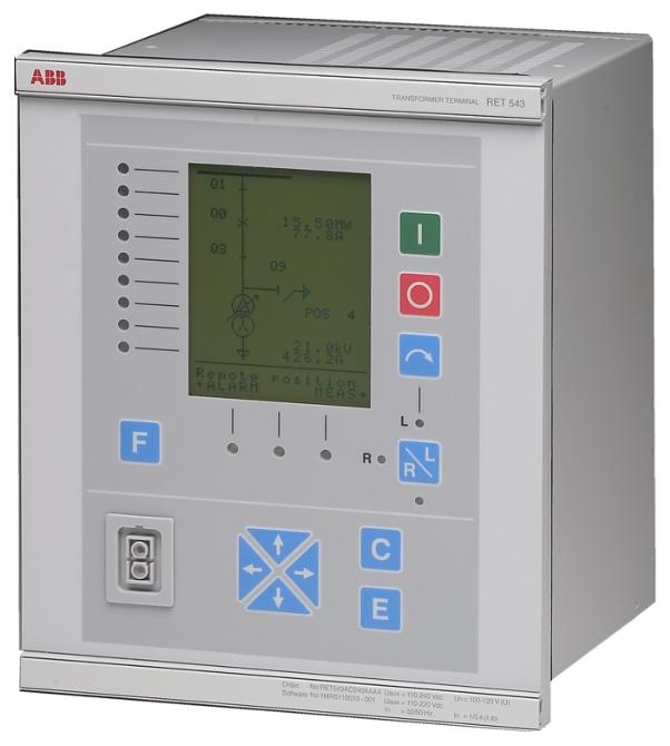
ABB REX 521 protective relay

Product positioning and hardware configuration

REX 521 is a multifunctional protective relay that supports multiple hardware versions (Basic/Medium/High/Sensor) and standard configurations (such as B01/B02/M01/H01, etc.), suitable for different voltage levels and protection requirements.

Hardware differences:

Basic: Basic type, supports basic overcurrent and ground fault protection, with fewer digital inputs/outputs.

Medium: Enhanced, extended digital input/output, supports directional protection and automatic reclosing.

High/Sensor: A high-end model that integrates advanced functions such as sensor interfaces, voltage/frequency protection, and motor start monitoring.
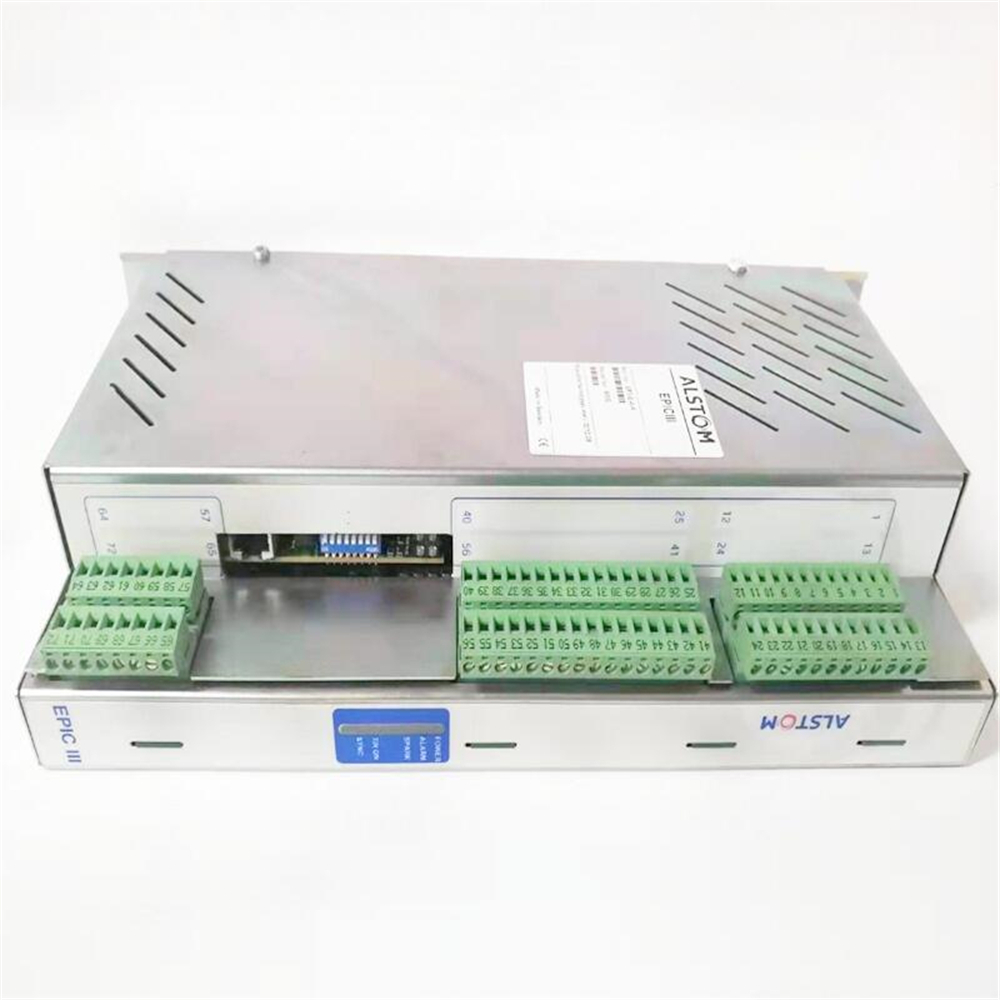
Key components:

Built in current/voltage transformer interface, supporting 1A/5A current and 100V voltage input.

Provide digital input/output, communication ports (RS-232/RS-485), and optional fiber optic modules, supporting protocols such as Modbus and DNP 3.0.

Core functions and protective features

1. Protection function

Overcurrent protection:

Supports three-phase overcurrent (3I>, 3I>>, 3I>>>) and ground fault (Io>, Io>>, Io>>>), including directional (67N) and non directional configurations, supporting definite time (DT) and inverse time (IDMT) characteristics.

Built in harmonic suppression and excitation inrush current detection (3I2f>) to avoid misoperation.

Voltage and frequency protection:

Overvoltage/undervoltage protection (3U>, 3U<<), residual voltage protection (Uo>), frequency anomaly protection (f1/f2), supporting voltage imbalance and phase sequence protection (U1U2<>_1).

Motor and transformer protection:

Motor start-up monitoring (Is2t n<), thermal overload protection (3Ithdev>), phase sequence reversal protection (3I()), fuse fault detection (FUSEF).

Automatic reclosing (O ->I):

Supports up to 5 reclosures, can be triggered by protection start or trip signals, and has dead time and discrimination time settings.

2. Measurement and monitoring

Electrical quantity measurement:

Real time measurement of three-phase current/voltage, power, frequency, and energy, supporting true RMS and fundamental wave analysis.

The disturbance recorder (DREC) can capture fault waveforms and supports manual or triggered recording.

Status monitoring:

Circuit breaker wear monitoring (CB wear1), trip circuit supervision (TCS1), power input supervision (MCS 3I/3U).

Power quality monitoring (PQ 3Inf/PQ 3Unf), supporting harmonic analysis and THD/TDD calculations.

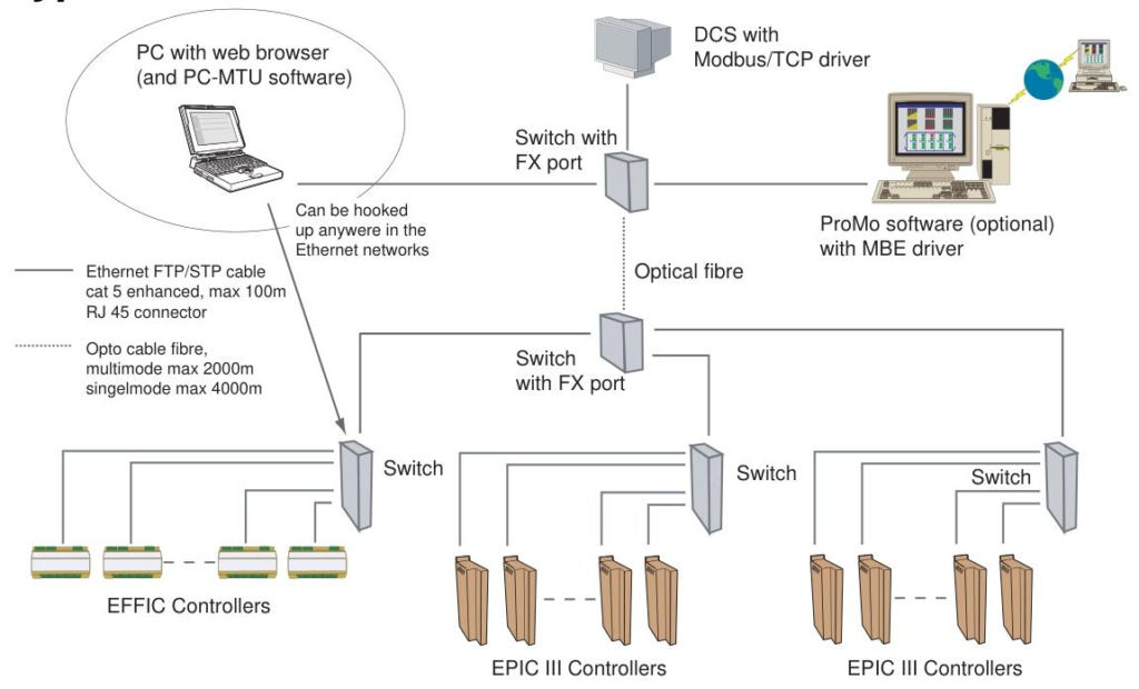
3. Communication and Control

Protocol support:

Standard SPA, Modbus RTU/ASCII, DNP 3.0, optional IEC 61850 adapter (requires expansion module).

​Remote control:

Support local/remote switching (I<->O POS), circuit breaker opening and closing control (I<->O CB1), and integrated interlocking logic.

3、 Standard configuration and application scenarios

1. Basic Configuration (Basic: B01/B02)

Function: Non directional overcurrent/ground fault protection, thermal overload protection, B02 supports automatic reclosing.

Application: Single busbar system for outgoing or incoming line protection, suitable for resistance grounding or solid grounded networks.

2. Intermediate configuration (Medium: M01/M02)

Function: Add directional grounding fault protection (67N), phase sequence protection, M02 supports reclosing and angle control (BACTRL).

Application: Compensate for grounding or isolated networks, requiring selective protection for outgoing scenarios.

Working principle of ABB RET 541/543/545 transformer terminals

RET 541/543/545 Transformer Terminal is a multifunctional protection and control device launched by ABB, mainly used for the protection, control, measurement, and monitoring of double winding power transformers and generator transformer units. Its working principle is based on four core links: data acquisition, logic processing, communication interaction, and execution control, combined with the characteristics of the power system to achieve precise protection and automation management. The following is a detailed analysis of the working principle:

Data acquisition and signal processing

Analog quantity acquisition

Real time collection of electrical quantities such as three-phase current (I ₁, I ₂, I ∝), neutral current (I ₀), phase voltage (U ₁, U ₂, U ∝), and zero sequence voltage (U ₀) through built-in current/voltage transformers (CT/PT) or external sensors.

The analog signal is converted into a digital quantity by an analog-to-digital converter (ADC) with an accuracy of ± 1%. It supports fundamental and harmonic analysis (such as 2nd harmonic braking to prevent excitation inrush current misoperation).

Digital quantity and status acquisition

Connect the position signals (DI) of circuit breakers, isolating switches, tap changers, as well as status signals such as gas pressure and spring energy storage.

Monitor the number of switch actions through a pulse counter, and collect non electrical quantities such as oil temperature and winding temperature through an RTD module (optional).

Protection logic processing

Real time analysis of collected data based on predefined protection algorithms and user configurations, triggering corresponding protection actions:

Current differential protection (87T)

Compare the current vectors on both sides of the transformer and distinguish internal and external faults through ratio braking characteristics.

Built in 2nd harmonic blocking and waveform recognition technology to avoid false tripping caused by CT saturation or excitation inrush current.

Overcurrent and ground fault protection

Three stage overcurrent protection: low setting value (NOC3Low), high setting value (NOC3High), transient period (NOC3Inst), supporting definite time (DT) and inverse time (IDMT) characteristics.

Zero sequence current protection (NEF1): detects grounding faults, supports high impedance principle (REF1A) and stable numerical principle (REF4A), and is compatible with different grounding systems.

Abnormal working condition protection

Overvoltage/undervoltage protection (OV3/UV3): Monitor the deviation of three-phase voltage from the rated value, trigger an alarm or trip.

Negative sequence current protection (NPS3): detects unbalanced loads or phase failure faults to prevent motor overheating.

Overexcitation protection (OE1): Monitor transformer core saturation through U/f ratio to avoid insulation damage.

Control and automation functions

Switchgear control

Control the opening and closing of the circuit breaker through the power output contact (PO), supporting local button operation or remote communication commands.

Tap changer automatic adjustment (COLTC): automatically adjusts the tap position according to voltage deviation, supports Master Follower mode (parallel transformer cooperative control), negative reactance principle or minimum circulating current control.

Interlocking and Logic Control

Implement interval interlocking through Boolean logic function blocks (such as AND/OR/timer) to prevent misoperation (such as the operation sequence of circuit breakers and isolating switches).

Support dynamic display of switch status, measured values, and alarm information on MIMIC interface, which can be interacted through HMI or remote SCADA system.

Status monitoring and maintenance

Circuit breaker status monitoring: Record the number of actions, travel time, degree of electrical wear (CMBWEAR1/2), and provide predictive maintenance reminders.

Trip Circuit Supervision (TCS): detects the integrity of the trip circuit through constant current injection to avoid the risk of refusal to operate.

Communication and System Integration

Multi protocol communication stack

Serial interface: Supports SPA, LON, Modbus RTU/ASCII, DNP 3.0, and is compatible with traditional SCADA systems.

IEC 61850 Integration: Connected to the IEC 61850 network through SPA-ZC 400 adapter, supporting GOOSE fast message (transmission delay<3ms) and SMV sampling value sharing, achieving substation level automation.

Data Interaction and Remote Management

Communicate with the station control layer through MMS protocol, upload measurement values, event records (SOE), and fault waveform data (MEDREC16).

Support IEEE 1588 v2 time synchronization to ensure data timestamp accuracy of ≤ 1 µ s across the entire network, meeting the requirements of distributed protection collaboration.

Workflow and Typical Scenarios

Normal operating mode

Continuously collect electrical quantities and status signals, display data in real-time through HMI or communication interface, and report measurement values to SCADA at set intervals (such as 1 second).

The tap changer automatically adjusts according to the voltage setting value to maintain stable secondary voltage.

Fault response mode

When an internal fault is detected (such as differential current exceeding the set value), immediately trigger a trip command (≤ 45ms) and send a fault signal to adjacent devices through GOOSE.

Record the fault waveform (MEDREC16), including data from multiple cycles before and after the fault, for fault analysis.

Maintenance and Configuration Mode

Download protection settings remotely through CAP 505 tool, modify logic function blocks, or adjust parameters locally through HMI.

Utilize self diagnostic functions to detect hardware faults (such as RAM/ROM verification, power supply abnormalities), and alert maintenance personnel through LED indicator lights and alarm outputs.

​Core technological advantages

Flexibility and Scalability: Adapt to different voltage levels and protection requirements through functional block programming (IEC 61131-3) and modular hardware (such as RTD modules).

Reliability: Industrial grade design (IP54 protection, -10 ° C~55 ° C operating temperature), EMC and vibration testing, suitable for harsh environments.

Standardization and interoperability: Supports IEC 61850 and multiple industrial protocols, compatible with third-party devices, and reduces system integration costs.

RET 541/543/545 achieves intelligent protection and control of power transformers through the above principles. Its core value lies in accurate fault identification, fast control response, and full lifecycle state management, making it a key component of modern intelligent substations.

615系列保护装置广泛应用于各大领域!-信海实业(深圳)有限公司

ABB RET 541/543/545 Transformer Terminal

Product positioning and functional overview

RET 541/543/545 is a multifunctional terminal designed specifically for dual winding transformers and generator transformer units in distribution networks, supporting harsh industrial, marine, and offshore applications. The core functions include:

Protection functions: three-phase current differential protection, overcurrent protection, ground fault protection, overvoltage/undervoltage protection, overheating protection, etc.

Control functions: local/remote switch control, interlocking logic, automatic control of tap changer (supporting multiple modes such as Master Follower).

Measurement and monitoring: three-phase current/voltage, power, frequency, energy measurement, circuit breaker status monitoring, self diagnostic function.

Communication capability: Supports protocols such as SPA, LON, IEC 60870-5-103, Modbus RTU/ASCII, DNP 3.0, etc., and can be connected to Profibus DP or IEC 61850 systems through adapters.

Core functional characteristics

Protection function

Current differential protection: with stable and instantaneous stages, supporting harmonic suppression and waveform recognition, suitable for CT saturation scenarios, supporting automatic matching of transformation ratios and vector groups.

Ground fault protection: supports high impedance principle and stable numerical principle, suitable for different grounding systems.

Backup protection: multi-stage overcurrent, negative sequence current, overexcitation, frequency anomaly protection, etc., meeting IEEE and IEC standards.

Control and Monitoring

Tap changer control: supports automatic voltage regulation of single or parallel transformers, with control modes such as Master Follower and negative impedance.

Status monitoring: monitoring of circuit breaker wear, gas pressure, and tripping circuit, supporting regular maintenance reminders.

Communication and Interface

Provide 3 serial communication ports (RS-232/RS-485), support fiber optic interface modules (RER 103/123/133), and adapt to different communication protocols and network topologies.

Support IEC 61850 standard (via SPA-ZC 400 adapter) to achieve substation automation system integration.

Hardware and Design

Model difference:

RET 541: Basic type, suitable for simple protection scenarios, with 15 digital inputs and low power output.

RET 543: Enhanced, with 25 digital inputs, supporting more power outputs and analog modules (RTD/analog modules).

RET 545: High end type, with 34 digital inputs and the highest power output, suitable for complex systems.

Hardware configuration:

Supports multiple current/voltage inputs (1A/5A, 100V, etc.), with built-in isolation transformers and analog-to-digital converters.

Optional fixed or external graphical display module (HMI), supporting multilingual interface and remote configuration.

The power module supports wide voltage input (DC 18-265V/AC 85-240V) and has undervoltage and overheating alarms.

Environmental adaptability:

Working temperature -10 ° C~+55 ° C, protection level IP54 (front side), tested for vibration, impact, and electromagnetic compatibility.

Application scenarios and engineering configurations

Typical applications:

Industrial substations, distribution networks, ship power systems, and generator transformer unit protection.

Support multiple transformer wiring methods such as Yd, Dyn, YNyn, etc., suitable for high resistance/low resistance grounding systems.

Engineering tools:

CAP 505: A graphical configuration tool based on IEC 61131-3, supporting functional block programming and MIMIC interface design.

Relay Mimic Editor: Used to configure HMI display and alarm logic.

Protocol Mapping Tool: Configure DNP 3.0 and Modbus interface parameters.

Configuration process:

Define protection logic, measurement points, and communication parameters through CAP 505.

Use IET600 or IEC 61850 Configuration tool to configure GOOSE/SMV communication (with IEC 61850 adapter RET 545).

Download the configuration to the device and verify its functionality through HMI or remote system.

Technical parameters and selection

Measurement accuracy: Current/voltage measurement error ≤ ± 1%, frequency accuracy ± 0.01Hz.

Trip time: The instantaneous action of differential protection is ≤ 45ms, and overcurrent protection can be set with timed or inverse time characteristics.

Ordering information:

The model suffix distinguishes the functional level (C=control type, B=basic type, M=multifunctional type).

Please specify the power type, number of digital I/O, communication protocol module, and display language.

Summary

The RET 541/543/545 series provides reliable automation solutions for power systems through highly integrated protection and control functions, flexible communication protocol support, and adaptability to harsh environments. Its modular design and standardized interfaces facilitate system integration and expansion, making it suitable for multi-level requirements ranging from simple power distribution to complex industrial scenarios. It is a key component of ABB’s substation automation product line.

What are the main advantages of the IEC 61850 standard?

The IEC 61850 standard is the core communication standard for intelligent substations and power system automation. Its main advantages are reflected in interoperability, layered architecture, real-time performance, reliability, engineering efficiency, and future scalability, significantly improving the intelligence level and operation efficiency of power systems. The following is a specific analysis of advantages:

Equipment interoperability and standardization

Unified Data Model and Communication Protocol

IEC 61850 adopts object-oriented modeling methods (such as logical nodes LN and data objects DO) to abstract functions such as protection, measurement, and control into standardized data models, breaking down the private protocol barriers of traditional devices. For example, protection relays and measurement devices from different manufacturers can exchange data through a unified GOOSE/SMV protocol, achieving “plug and play” functionality.

Eliminate vendor lock-in

Based on open standard communication interfaces such as MMS and TCP/IP, users can flexibly choose devices from different vendors to build systems, reducing dependence on a single supplier and improving the flexibility and cost-effectiveness of system integration.

Hierarchical distributed architecture

Clear three-tier architecture

Station control layer (SCADA system): Data monitoring and management are achieved through MMS protocol.

Interval layer (protective measurement and control device): Fast tripping command transmission is achieved through GOOSE, and sampling value sharing is achieved through SMV.

Process layer (intelligent terminal, merging unit): Based on IEEE 1588 time synchronization, real-time acquisition and execution of switch and analog quantities are achieved.

Function distribution optimization

Support distributed function configuration, such as anti misoperation locking, backup automatic switching, etc., which can be distributed across different devices at different intervals, and work together through high-speed communication to reduce the complexity of centralized systems.

High speed real-time communication capability

GOOSE Fast Message Mechanism

By adopting multicast communication and event triggering mechanism, the transmission delay can be as low as milliseconds, meeting the requirement of rapid tripping between protection devices (such as differential protection).

Support Heartbeat mechanism and ConfRev configuration version verification to ensure real-time monitoring and data consistency of communication links.

SMV sampling value transmission

Supports the IEC 61850-9-2 LE protocol to transmit current/voltage sampling values at a fixed sampling rate (such as 4000 points/second), replacing traditional cable analog transmission, reducing hardware wiring and improving accuracy.

Combining IEEE 1588 v2 time synchronization, microsecond level synchronization of sampling values across the entire network is achieved, supporting distributed protection and synchronous phasor measurement.

High reliability and redundant design

Network redundancy topology

Support HSR (High Availability Seamless Redundant Ring Network) and PRP (Parallel Redundancy Protocol), which can automatically switch when a single link or device fails, ensuring communication continuity.

The switch supports VLAN partitioning and traffic priority setting (such as GOOSE/SMV priority transmission) to avoid network congestion affecting critical services.

Fault diagnosis and self-healing

Built in communication diagnostic counters (such as GSELPRT1, MMSLPRT1), real-time monitoring of message sending and receiving status, configuration conflicts (such as IP address duplication), and time synchronization errors.

Support “Test Bit” to verify configuration changes without affecting actual operation, reducing debugging risks.

Engineering efficiency and maintenance convenience

Model driven engineering tools

Use SCL (Substation Configuration Language) to uniformly describe the system structure, equipment parameters, and communication connections, and use tools such as PCM600 and IET600 to achieve graphical configuration and batch parameter distribution, reducing manual configuration errors.

Support version management and comparison of configuration files (such as SCD file difference analysis), facilitating engineering changes and version traceability.

Remote operation and diagnosis

Based on web servers and MMS protocol, device parameters, fault recording, and real-time data can be remotely accessed through a browser, reducing on-site maintenance workload.

Support remote firmware upgrade and batch configuration synchronization to shorten the system upgrade cycle.

Support smart grid and future expansion

Facing digital transformation

Support IEC 61850-7-420 extensions (such as new energy access, energy storage system modeling) to meet the integration requirements of distributed energy (DER) and microgrids.

Compatible with the Internet of Things (IoT) and big data analysis, device data is connected to the cloud platform through standardized interfaces, supporting intelligent operation and predictive maintenance.

Protocol scalability

The modular design can flexibly expand new logic nodes (such as electric vehicle charging interface LN) and communication services to meet the future technological evolution (such as 5G, edge computing).

Reduce full lifecycle costs

Reduce hardware investment

Replace traditional secondary cables (such as trip circuits and analog circuits) with network communication to reduce cable procurement, laying, and maintenance costs.

A unified communication platform reduces the use of interface conversion devices (such as protocol converters) and simplifies system architecture.

Improve operational efficiency

Shorten fault location time through standardized fault reporting and event recording (such as SOE sequential event recording).

Support “plug and play” device replacement, new devices can automatically load configuration files, reducing power outage time.

summarize

The IEC 61850 standard solves the protocol barriers and operational challenges of traditional power systems through standardized interoperability, real-time communication, redundant architecture, and efficient engineering tools. It is the foundation of intelligent substations and power IoT. Its advantages are not only reflected in the current integration of automation systems, but also lay the foundation for the digital and intelligent upgrading of future power grids, becoming the mainstream communication standard in the global power industry.

ABB 620 Series IEC 61850 Engineering Guidelines

​Overview of IEC 61850 Standard

standard framework

IEC 61850 is an international standard for substation communication and systems, which defines an object-oriented data model and communication services, supports device interoperability, and is divided into multiple parts (such as data model, communication protocol, configuration language, etc.). It supports Edition 1 and Edition 2 versions, which have differences in data model and functionality. It is recommended to unify the versions in the project.

communications architecture

Vertical communication: Based on MMS (Manufacturing Message Specification) and TCP/IP, used for communication between controllers and upper level systems such as SCADA.

Horizontal communication: GOOSE (General Object Oriented Substation Events) and SMV (Sampling Values) are used to achieve fast data exchange between devices, supporting IEEE 1588 v2 time synchronization.

Tools and Configuration Process

PCM600 tool

Used for the full lifecycle management of protective relays, supporting engineering design, configuration, debugging, and monitoring.

Adapting different models of devices through ‘Connectivity Packages’ requires communication configuration using the IEC 61850 Configuration tool.

IET600 tool

Focused on IEC 61850 system level configuration, supports importing/exporting SCD files, and achieves centralized management of communication parameters such as GOOSE and SMV.

Collaborate with PCM600 to exchange configuration data through SCL files and support third-party device integration.

configuration process

Device definition: Create a project and add devices in PCM600, export SCD files to IET600.

Communication configuration: Configure GOOSE publish/subscribe, SMV transmission parameters, IEEE 1588 time synchronization, etc. in IET600.

Function mapping: Use the Signal Matrix tool to map GOOSE/SMV data to protection function blocks, completing application logic connections.

Verification and Download: Export the configuration to PCM600, write it to the device, and verify the communication status.

Core communication function configuration

GOOSE Communication

Data Model: Based on the Data Set and GOOSE Control Block (GoCB), supporting the transmission of state and analog variables, with a response time of less than 3ms.

Configuration points:

Unique multicast address and APP ID to avoid VLAN configuration conflicts.

Define data entries and subscription relationships through PCM600’s IEC 61850 Configuration tool or IET600.

Diagnostic counters (such as FrRxCnt, RxTmOutCnt) are used to monitor communication status.

SMV (Sampling Value) Communication

Support IEC 61850-9-2 LE protocol, transmit current/voltage sampling values, with a sampling rate of 4000 points/second (50Hz system).

Time synchronization: relying on IEEE 1588 v2 PTP protocol, supporting HSR/PRP redundant topology, ensuring microsecond level synchronization accuracy.

Configuration restriction: The SMV dataset cannot be manually modified and needs to be activated through the SMVSENDER function block. The receiving end processes the data through the TVTR module.

Event Reporting

Based on the report control block (RCB) and dataset, it supports buffered and non buffered report modes.

The triggering conditions include data change, quality change, etc. The report content and target client can be defined through PCM600.

System architecture and redundancy design

network topology

HSR (High Availability Seamless Redundancy): A ring network with nodes supporting dual port redundancy, with a maximum of 30 devices, suitable for high reliability scenarios.

PRP (Parallel Redundancy Protocol): Double star network, devices are connected through LAN A/B dual ports, supporting single node redundancy box (RedBox).

IEEE 1588 v2 Time Synchronization

Following IEEE C37.238-2011 power configuration file, supporting one-step mode and transparent clock.

The priority of the master clock is set through PTP Priority 1/2, with an accuracy of ≤± 1 µ s to ensure synchronization of SMV sampling values.

performance optimization

The switch needs to support VLAN partitioning and SMV traffic filtering to avoid broadcast storms.

The maximum delay of SMV needs to be configured according to the number of network hops, with a typical value of 2-7ms, to ensure real-time protection function.

Engineering Verification and Maintenance

Verification process

Functional testing: Use the Signal Monitoring tool of PCM600 to forcibly send GOOSE signals and verify the status updates of the receiving end.

Time synchronization check: Monitor the synchronization status of IEEE 1588 (such as Sync Accuracy<4 µ s) to ensure consistent clocks across the entire network.

Redundancy testing: Simulate a main clock failure to verify the continuity of backup clock takeover and SMV transmission.

Diagnosis and Maintenance

Logs and counters: View GSELPRT1 (GOOSE diagnosis) and MMSLPRT1 (MMS diagnosis) counters through the device LCD interface or PCM600.

Firmware upgrade: Update device firmware and Connectivity Packages through PCM600’s Update Manager to ensure compatibility.

Safety precautions

Backup project files before configuration to avoid data loss caused by misoperation.

Third party devices must support IEEE 1588 v2 and Power Profile to ensure interoperability.

Terminology and Abbreviations

GOOSE: General object-oriented substation event for fast status transmission.

SMV: Sampling Value, used for transmitting analog data such as current and voltage.

HSR/PRP: High availability seamless redundancy/parallel redundancy protocol to enhance network reliability.

PTP: Precision Time Protocol (IEEE 1588), achieving nanosecond level time synchronization.

SCL/SCD/ICD/CID: IEC 61850 configuration language and file format, used for device description and system integration.

summarize

This guide comprehensively covers the IEC 61850 engineering design of ABB 620 series equipment, providing detailed process and parameter recommendations from standard principles to tool operation, from communication configuration to system verification. It is suitable for the design and implementation of automation systems in smart substations, ensuring efficient interoperability and reliable communication between equipment.

ALSTOM EP3-G-4-A-PT Controller

Ethernet standards and component requirements

Communication standards

Adopting 100Mbps Ethernet, supporting TCP/IP protocol, suitable for ALSTOM’s EPIC, FIC and other controllers.

Industrial standard: Switches must comply with EN 50082-2 or EN 61000-6-2 electromagnetic compatibility (EMC) standards, and HMS or Hirschman brands are recommended.

Network components

Switch: Industrial grade switches must be used, and hubs must be disabled (affecting performance).

Cable: Cat 5E FTP twisted pair cable (RJ45 interface) is recommended, with fiber optic mode supporting up to 4000 meters of transmission.

Controller interface: RJ45 10/100M adaptive port, supporting automatic speed negotiation.

Protocol and Ports

Common ports: 80 (HTTP), 502 (Modbus/TCP), 20/21 (FTP), 3250 (PC-MTU configuration).

Disable router: Do not access the router in the network, otherwise PC-MTU and master station functions may fail.

Network setup and IP configuration

software tool

PC-MTU software: used for configuring and monitoring multiple controllers, requiring the controller to have a built-in web server (accessed through a browser).

System requirements: Windows 2000/XP system, IE 6.0+browser, processor ≥ 300MHz, memory ≥ 128MB.

IP address allocation

Manual configuration (DIP switch):

The default IP is 192.168.0. X (X is set through an 8-bit DIP switch, binary to decimal, range 1-255).

Step: Turn off the controller → Set DIP switch → Restart → Configure PC IP (same network segment, such as 192.168.0.100) → Scan the network through PC-MTU.

DHCP automatic allocation: Check the DHCP option and enable DNS (controller names must be unique).

Network verification

The “IP Config” window of PC-MTU identifies controller status by color:

Red: Declared but not connected; Blue: Undeclared but online; White: Normal connection.

Support batch replication configuration: Single controller settings can be quickly synchronized to other devices.

Operation and monitoring functions

PC-MTU main interface

Real time display of controller name, number, status (voltage, pressure, current, etc.), and alarm information.

Double clicking on the controller name will redirect you to a web page for parameter configuration or firmware upgrade.

Alarm and Control

Alarm types: red (trip alarm, controller automatically shuts down), yellow (warning alarm), double-click to view detailed logs.

Remote operation: Reset the alarm and start stop controller (HV button) through interface buttons.

MENU

Advanced: IP configuration, password modification, switching working directory.

View: Save/load layout, lock interface (password required), enable alarm sound prompt.

Key basis for troubleshooting

LED status diagnosis

LED 1 (green): Always on indicates link connectivity, off indicates no connection (check cable or switch port).

LED 2 (red): The flashing frequency corresponds to different faults (such as IP conflict, MAC address error, flash configuration loading failure).

LED 4 (green): Flashing indicates normal data transmission and reception. If it does not light up, it may be a port or protocol failure.

IP address conflict handling

When duplicate IPs are detected through PC-MTU scanning, DIP switches or DHCP parameters need to be reset to ensure uniqueness.

Network component validation

Switch failure: Replace the port or switch and observe if the LED status is restored.

Router existence: Remove routers from the network to avoid interference with PC-MTU and controller communication.

Terminology and Precautions

Modbus/TCP: Industrial communication protocol used for data exchange between controllers and upper computers.

Master: Monitor controllers within a specified range (such as range 5-10, and synchronously shut down controllers within that range when the master is turned off).

Attention: After configuration is completed, save the settings to the controller flash memory and restart to take effect; Prohibit the use of hubs or routers in the network.

summarize

This manual provides a comprehensive guide for the entire process from network design, software installation to troubleshooting. The core is to achieve efficient Ethernet configuration and monitoring through the collaboration of PC-MTU software and controller web interface. Suitable for centralized management of multiple controllers in industrial automation scenarios, especially for communication integration of devices such as electrostatic precipitators (ESP) and filtration systems, emphasizing the value of IP uniqueness, industrial grade component selection, and LED status fault location.

ALSTOM EP3-E-4-A Electrostatic precipitator controller Hot selling ...

How to troubleshoot Ethernet faults in EPIC III series controllers?

To troubleshoot Ethernet faults in EPIC III series controllers, one can start with hardware connections, IP address settings, software functionality, and network components. First, check if the physical connection is normal, then check if the IP address conflicts or is configured incorrectly, then check if there are any abnormalities in software operation, and finally investigate if there are any problems with network components.

Hardware connection check

Cable connection: EPIC III series controllers use Cat 5E FTP cables with RJ45 connectors. Check whether the cable is damaged or bent, and whether the RJ45 interface is loose. You can confirm whether the connection is good by re plugging and unplugging the cable. If there is obvious damage to the appearance of the cable, a new cable needs to be replaced.

Controller Ethernet Port: The Ethernet port of the controller is RJ45 10/100M/bit auto negotiation type. Check the appearance of the port for any damage, such as bent or broken pins. If the port is damaged, it may be necessary to repair or replace the Ethernet module of the controller.

Switch ports: The Ethernet switch ports connected to the controller also need to be checked. Check if the indicator light corresponding to the switch port is on. If it is not on, try replacing the switch port for connection to determine if it is a switch port failure.

IP address setting check

Uniqueness check: Each controller must have a unique IP address in the network. Scan the network through the IP config window of PC-MTU software to see if there are duplicate IP addresses. If there is a duplication, follow the method of setting the IP address in the manual, such as using the configuration switch to reset, to ensure that the IP address of each controller is unique.

Configuration correctness check: Confirm that the IP address, subnet mask, and gateway configuration of the controller are correct. You can refer to the steps in the manual to set the IP address using configuration switches, specific IP numbers, or DHCP, and check if the settings meet the requirements. If using DHCP, it is necessary to ensure that the DHCP server is working properly and configured correctly.

Software operation check

PC-MTU software: PC-MTU software is used to set up, operate, and monitor controllers in a network. Check if the software can be opened normally. If it cannot be opened, check if it meets the system requirements of the software, such as whether the operating system is Microsoft Windows ®  2000 or Microsoft Windows XP ®, Is Microsoft Internet Explorer installed ®  Is the memory at least 128MB for version 6.0 or higher. If the software has abnormal functions after opening, such as being unable to scan the controller, you can try reinstalling the software.

Controller Web Page: Double click the controller name using PC-MTU software to access its web page. If unable to access, check the network connection and IP address settings, and also check if the controller’s web server is running properly. You can try accessing it using other browsers or view the controller’s log files (if available) to obtain more information about the running status of the web server.

Network component inspection

Ethernet switch: Ethernet switches should comply with EMC immunity for industry EN 50082-2 or EN 61000-6-2 standards. Check the working status of the switch, check whether the indicator lights of the switch are displaying normally, and whether there are any error messages. If the switch malfunctions, it may cause abnormal network connections. You can try replacing the switch for testing.

Router: Routers should not be installed in EPIC III Ethernet networks as PCMTU and main functions may not function properly through the router. Check if the router is accidentally connected to the network, and if so, remove the router before testing the network connection.

ALSTOM EPIC III series controllers

ALSTOM EPIC III series controllers

Ethernet standards and component requirements

generic standard

Adopting 100Mbps Ethernet as the communication standard, it is suitable for EPIC, FIC and other controllers under ALSTOM Power Service.

Reference industry standard: EMC immunity must comply with EN 50082-2 or EN 61000-6-2.

Network components

Switch: It is recommended to use HMS or Hirschman brands, which must meet industrial grade anti-interference requirements and avoid using hubs (affecting performance).

Cable: It is recommended to use Cat 5E FTP cable (RJ45 interface), which supports up to 4000 meters of transmission in fiber mode.

Controller interface: RJ45 10/100M adaptive Ethernet port, supporting automatic rate negotiation.

Protocol and Ports

Port allocation:

20/21 (FTP), 80 (HTTP), 502 (Modbus/TCP), 3250 (PC-MTU IP configuration), 49200/49201 (main station function).

Disable device: Do not install routers in the network, otherwise PC-MTU and master station functions may fail.

​Steps for building an Ethernet network

Software installation and system requirements

PC-MTU software: used to configure and monitor multiple controllers in a network, which needs to be paired with the built-in web server of the controller (accessed through a browser).

System configuration:

Processor: 300MHz or above (recommended Intel/AMD mainstream processors).

Memory: At least 128MB RAM, operating system supports Windows 2000/XP, browser requires IE 6.0+.

IP address allocation

Manual configuration (DIP switch):

The default IP of the controller is 192.168.0. X (X is set through an 8-bit DIP switch, binary to decimal, range 1-255).

Step: Turn off the controller → Set DIP switch → Restart → Configure PC IP (same network segment as the controller, such as 192.168.0.100) → Scan the network through PC-MTU.

DHCP automatic allocation: Check the DHCP option and save the configuration, which needs to be paired with a DNS server (controller name must be unique).

Network verification and configuration

Scan the controller through the “IP Config” window of PC-MTU, and the status color indicates:

Red: Declared but not connected; Blue: Undeclared but online; White: Normal connection.

Support batch replication configuration: Save the settings of a single controller to a PC and quickly synchronize them to other controllers.

Operation and monitoring

PC-MTU main window

Display the names, numbers, status (real-time data such as voltage, pressure, current, etc.), and alarm information of all controllers in the network.

Double clicking on the controller name will take you to its built-in web page for detailed parameter configuration.

Alarm and Control

Alarm indication: red (trip alarm, controller automatically shuts down), yellow (warning alarm), double-click to view the specific alarm page.

Operation function: Reset the alarm and remote start stop controller (HV button) through interface buttons.

MENU

File: Exit the software and print the current interface.

View: Save/load layout, resize text, lock layout (password required), set alarm sound.

Advanced: IP configuration, password modification, switching working directory.

Terminology and Precautions

Key terms

Modbus/TCP: an industrial communication protocol based on TCP/IP, used for data exchange between devices.

DHCP/DNS: Dynamic IP allocation and domain name resolution services that need to be used in conjunction to support controller name access.

Master: Responsible for monitoring controllers within a specified range (such as setting a range of 5-10, and synchronously shutting down controllers within that range when the Master is turned off).

Precautions

Ensure that each controller IP is unique to avoid address conflicts (DIP switch or DHCP can be used).

Prohibit the use of routers in the network, prioritize industrial grade switches to ensure stability.

After the configuration is completed, the settings need to be saved to the controller’s flash memory and restarted to take effect.

summarize

This manual provides a full process guide from network design, software installation to daily operation, with the core being the efficient configuration and monitoring of Ethernet networks through the collaboration of PC-MTU software and the controller’s built-in web server. Suitable for centralized management of multiple controllers in industrial automation scenarios, especially in communication integration of devices such as electrostatic precipitators (ESP) and filtration systems, it has practical application value.

Alstom Advanced Micro Controller 2

Product Overview: AMC2 is a main controller box for AMC-PLC, AMC-AU, and AMC-DP, designed by Converteam and supplied by Eltech, using the Arbor EmE7x-i701 controller board. This is a small and sturdy flange mounting box that can be installed on vertical panels, fanless, with a temperature rating of 70 ° C. After type testing, it has shock resistance and other characteristics. Based on commercial off the shelf Pentium M-class embedded CPU, it has low cost and multiple configurations to choose from. It is used in fields such as ship architecture, PEC drive controllers, and general-purpose PLCs.

Specification parameters:

CPU: 600MHz Celeron M, or special order for 1.40GHz Pentium M version.

Memory: 256MB DRAM, 256MB Compact Flash.

Power supply: 24V DC ± 20% power supply, consuming approximately 0.9A.

Interface: 5 LAN ports, 4 serial links (RS232), 3 available for application; 2 USB ports (Shan Yi latch system); 4 PMC/PC104+expansion slots, suitable for 16 channel Serial 16+FIP, Profibus master, slave fieldbus, fiber optic Ethernet, etc.

Other: fanless, watchdog, temperature monitoring, removable compact flash drive; The supported software platforms include Marine Controller (Isagraf) HPCi, etc.

Size: 234x206x120mm.

Ordering code: AMC2 has multiple configurations, each corresponding to a different ordering code, such as different quantities of Serial 16+, FIP cards, Profibus master/slave ports, etc. Users only need to specify the ordering code. For Pentium-M 1.40 GHz version, please contact the ship procurement department.

Software License: AMC controllers require a VxWorks runtime license, which can be obtained by contacting the ship procurement department for necessary licensing advice.

Hardware performance and processing capability

processor performance

The basic configuration is a 600MHz Celeron M processor, with performance approximately twice that of the previous generation AMC1 controller (depending on the application code).

Support special ordering of 1.40GHz Pentium-M processors to further enhance data processing and multitasking capabilities, suitable for scenarios with higher computing performance requirements (such as complex algorithms or real-time control).

Memory and Storage

Equipped with 256MB DRAM and 256MB Compact Flash, it supports storing programs, configuration files, and real-time data.

Flash memory is removable, facilitating data backup and system upgrades, and improving maintenance convenience.

Fanless design and environmental adaptability

Adopting passive heat dissipation design, it can operate stably in a high temperature environment of 70 ° C without the need for a fan, suitable for harsh industrial environments such as dust and vibration.

Through 15g impact testing (IEC1131 standard), it has high reliability and anti-interference ability, meeting the stringent requirements of shipbuilding, heavy industry and other scenarios.

Communication and Expansion Capability

Rich interface configuration

5 Ethernet ports: Supports high-speed data transmission and can simultaneously connect multiple devices or networks (such as fieldbus, monitoring system) to achieve distributed control and data exchange.

4 RS232 serial interfaces (3 available for application): compatible with traditional industrial equipment (such as sensors, frequency converters), supports protocols such as Modbus, and adapts to the integration requirements of old systems.

2 USB ports (Shan Yi Lock System): Used for external storage devices or debugging tools, facilitating program downloads and data exports.

Flexible extension functions

Provide 4 PMC/PC104+expansion slots, supporting multiple function card extensions:

Serial 16+card: adds 16 channels of serial communication, suitable for scenarios that require a large number of serial devices (such as ship DP systems).

Profibus Master/Slave Card: Compatible with Profibus fieldbus, enabling real-time communication with devices such as PLCs and drives.

FIP card (Factory Interface Protocol): used for fast data exchange in ship automation systems, supporting DP (Dynamic Positioning) upgrades.

Fiber optic Ethernet module: expands long-distance high-speed communication, suitable for the long-distance transmission needs of industrial networks.

Software and System Integration

Multi platform compatibility

Supports VxWorks real-time operating system (requires separate purchase of operating license), with high real-time performance and stability, suitable for control tasks with strict response speed requirements (such as ship dynamic positioning).

Optional Windows XP system (order code P106-6052), convenient for general embedded PC applications such as human-machine interface and data monitoring.

Pre installed Isagraf HPCi software platform supports PLC programming and ship controller development, simplifying the deployment of industrial automation programs.

System monitoring and maintenance

LED status indicator: Real time display of power, health, and running status, facilitating quick troubleshooting.

Watchdog timer: prevents system crashes, automatically restores abnormal states, and improves reliability.

Temperature monitoring: Built in sensors monitor the internal temperature in real-time to avoid performance degradation or hardware damage caused by overheating.

Typical application scenarios

Ship and Ocean Engineering: As a DP (Dynamic Positioning) controller, on-site PLC or redundant module, multi device collaborative control is achieved through FIP and Profibus interfaces to ensure the stability of the ship in complex sea conditions.

Industrial automation: used for PEC drive controllers, general PLC systems, supporting multi axis motion control, production line monitoring and other scenarios, compatible with traditional and modern industrial protocols.

Embedded control: With its compact size (234x206x120mm) and low-power design (24V DC power supply, 0.9A current), it is suitable for distributed control systems with limited space.

summarize

The AMC2 controller exhibits balanced comprehensive performance in the industrial control field through high-performance hardware, flexible expansion interfaces, strong environmental adaptability, and multi system compatibility, making it particularly suitable for scenarios that require high reliability and customized communication configurations (such as ship automation and complex production lines). Users can choose different expansion modules (such as Serial 16+, Profibus card) according to their specific needs to optimize system integration efficiency.

Train Control and Information Systems: Digitalising for the future | Alstom

STUDER communicator A8600 controller

Product overview

The STUDER communicator A8600 controller is a core controller designed by STUDER specifically for communication and control of precision machining equipment. It undertakes key tasks such as data communication, instruction processing, and equipment coordination during the operation of precision machining equipment, and is the central brain that ensures the efficient and precise operation of the equipment. By stable communication with various components of the machine tool and external systems, the A8600 controller can achieve precise control of the machining process, ensuring that machining accuracy and production efficiency reach industry-leading levels.

Specification parameters

Communication Interface: Equipped with a variety of communication interfaces, including Ethernet interfaces, supporting high-speed and stable data transmission, making it easy to connect with factory networks and computer systems for remote monitoring and program transmission; Serial communication interfaces such as RS-232 and RS-485 can reliably communicate with various sensors and actuators, meeting the communication needs between different devices; In addition, it may also have a USB interface for quick storage and transfer of data, such as backup of processing parameters, import and export of program files, etc.

Control accuracy: Based on advanced algorithms and high-precision hardware design, the A8600 controller can achieve control accuracy at the micrometer or even nanometer level, ensuring that the moving parts of the machine tool can operate accurately according to preset instructions in precision grinding, milling and other machining processes, meeting the processing requirements of complex precision parts.

Data processing capability: Equipped with a high-performance processor and large capacity memory, it has powerful data processing capabilities and can quickly process large amounts of processing instructions, sensor data, and communication information, ensuring that the device can maintain stable and accurate control during high-speed operation.

Adaptability to working environment: It has good adaptability to working environment, can operate stably within a certain temperature and humidity range, and can resist the influence of electromagnetic interference, dust and other factors in industrial environment, ensuring reliable operation in harsh production workshop environment. Its working temperature range is generally around 0 ℃ -45 ℃, and the relative humidity range is 20% -80% (without condensation).

Core functions

Equipment communication and coordination: As the core hub of equipment communication, the A8600 controller can achieve efficient communication between various components of the machine tool, ensuring collaborative work between the spindle, feed axis, grinding wheel dresser, and other components. At the same time, it can also communicate with external systems such as computer-aided design/manufacturing (CAD/CAM) systems and production management systems, receive processing instructions, production plans, and other information, and provide feedback on equipment operation status to external systems, achieving automation and information-based management of production processes.

Process control: During the machining process, the A8600 controller can accurately control the motion trajectory, speed, feed rate, and other parameters of the machine tool according to preset machining parameters and process requirements. By monitoring sensor data in real-time, such as position sensors, force sensors, etc., the machining process can be dynamically adjusted to ensure machining accuracy and surface quality. For example, in grinding, the feed rate of the grinding wheel can be adjusted in real time according to the size changes of the workpiece to ensure the consistency of the machining dimensions.

Fault diagnosis and alarm: Equipped with an intelligent fault diagnosis system, it can monitor the operating status of equipment in real time and provide early warning and diagnosis for possible faults. Once a fault is detected, such as motor overload, sensor abnormality, communication interruption, etc., the A8600 controller will immediately issue an audible and visual alarm signal and display detailed fault information on the operation interface, helping maintenance personnel quickly locate the cause of the fault, shorten equipment downtime, and improve production efficiency.

Working principle

The A8600 controller receives processing instructions, parameter settings, and other information from external systems through a communication interface, and stores this information in internal memory. The processor inside the controller parses and processes this information, generating corresponding control signals. These control signals are transmitted through drive circuits to various actuators of the machine tool, such as servo motors, hydraulic valves, etc., to control the movement and actions of the machine tool. At the same time, sensors provide feedback on the operating status of various components of the machine tool, such as position, speed, temperature, etc., to the A8600 controller. The controller performs real-time analysis and comparison of feedback information, compares it with preset parameters, and adjusts the control signal in a timely manner if there is a deviation, so as to restore the operating state of the machine tool to the correct parameter range, thereby achieving closed-loop control and ensuring the accuracy and stability of the machining process.

FEATURES AND BENEFITS

• Four independent, high current switching regulators

• Adjustable 1.0 A/±1.5% always-on asynchronous buck

regulator with an integrated 150 mΩ MOSFET (SW1)

▫ Employs PFM to deliver 3.3 V/40 µA while drawing less

than 50 µA from VIN of 12 V

▫ Operates down to at least 3.6 VIN

• Adjustable 1.5 A/±1.5% asynchronous buck regulator with

an integrated 120 mΩ high-side MOSFET (SW2)

• Adjustable 2.0 A/±1.5% asynchronous buck regulator with

an integrated 110 mΩ MOSFET (SW3)

• Adjustable ±1.5% synchronous buck controller with

integrated gate drivers and current sensing (SW4)

• Fixed 425 kHz, interleaved PWM switching frequency

• EN/SYNC input for PWM frequency scaling

• Adjustable soft-start time for each switching regulator

• All switching regulators provide pre-bias startup with zero

reverse current

• All switching regulators have overvoltage protection

• External compensation for all switching regulators

Precautions

Installation and wiring: When installing the A8600 controller, it is necessary to strictly follow the requirements of the product manual to ensure a stable installation position and correct wiring. Pay attention to the standardization of electrical connections to avoid equipment damage or communication failures caused by wiring errors. At the same time, grounding protection should be implemented to prevent electromagnetic interference from affecting the controller.

Environmental requirements: Ensure that the working environment of the controller meets its specified temperature, humidity, dust prevention, and other requirements. Avoid installing the controller in environments with high temperature, humidity, corrosive gases, or strong electromagnetic interference to avoid affecting its performance and service life. Regularly clean the controller to prevent dust accumulation from affecting heat dissipation and normal operation.

Software management: Timely follow the official software update information released by STUDER, upgrade the software of the controller according to the correct process to obtain new features and performance optimization. Before upgrading software, it is essential to backup important programs and data to prevent data loss. At the same time, it is important to ensure the use of genuine software to avoid compatibility issues and security risks caused by the use of pirated software.

Maintenance and upkeep: Regularly inspect and maintain the A8600 controller, check whether the interface connections are secure, and whether the cooling fan is operating normally. For controllers that have malfunctioned, they should be repaired by professional maintenance personnel to avoid unauthorized disassembly and repair by non professionals, in order to prevent greater damage.

Search for products

Back to Top
Product has been added to your cart