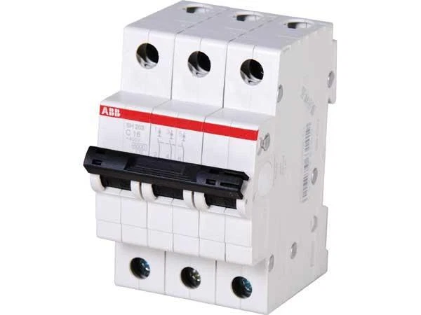
Positioning: The S500 series is a high-performance miniature circuit breaker (MCB) that complies with UL 1077 standards and is used for circuit protection, supporting both alternating current (AC) and direct current (DC) systems.
Core function: Provides thermal magnetic trip protection, with high breaking capacity and fast breaking time (2.3-2.5s), suitable for overload and short circuit protection of industrial and commercial circuits.
Model and Technical Parameters
S500 (AC model)
Voltage range:
UL standard: 600Y/277 VAC
IEC standard: 690 VAC
Current range: 0.1-45 A (unipolar/bipolar/triode)
Tripping characteristics: Only K-curve (applicable to inductive loads, allowing high surge currents during startup, such as motors and transformers).
Breaking capacity: up to 30 kA (UL 1077/CSA C22.2).
S500UC (DC model)
Voltage range:
Single pole: 250 VDC
Quadrupole: 750 VDC
Current range: 0.1-63 A (unipolar/bipolar/triode/quadrupole)
Release characteristics: B curve (applicable to DC inductive loads) and K curve (optional).
Breaking capacity: up to 30 kA (UL 1077/CSA C22.2).
Core features
Design and Installation
Rail installation: Supports 35mm DIN rail installation, saving space.
Safe terminals: designed to prevent electric shock (Finger safe terminals), supporting multi-functional terminal connections.
Compact size: The width of a single pole is about 17.5mm, and the width of a multi pole model increases proportionally (such as 35mm for 2-pole and 52.5mm for 3-pole).
Protection function
Thermal magnetic trip: Combined with overload (thermal) and short circuit (magnetic) protection, it responds quickly.
Adjustable trip unit: supports current regulation and adapts to different load requirements.
Certification and Compliance
Compliant with UL 1077, CSA C22.2, IEC 60497-2 and other standards, with CE certification.
Model specifications and prices (some examples)
Model, Pole, Current Range, Catalog Number, Price (Example)
S500-K 1 2.8–4.2 A S501-K4.2
S500UC-B 1 6 A S501UC-B6
S503-K4.2 3 2.8–4.2 A S503-K4.2
S504UC-K4.2 4 2.8–4.2 A S504UC-K4.2
Attachments and extensions
Auxiliary contacts
Provide status feedback (such as on-off signals), supporting 1 normally open/1 normally closed (S500-H11) or 2 normally open (S500-H20)
Bell alarm
Trigger alarm when tripping, with test button (such as S500-S11)
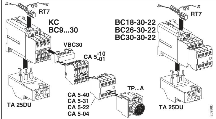
Model positioning: Belonging to ABB BC series contactors, suitable for on/off control of industrial circuits, commonly used in scenarios such as motor drives and power distribution systems.
Category: Contactor, mainly used for frequent connection and disconnection of load circuits, with arc extinguishing capability.
Key technical parameters
Electrical parameters
Rated voltage:
Control coil voltage (U c): Supports 24V DC~250V DC (please refer to the specific nameplate).
Main circuit voltage: suitable for industrial standard voltage levels such as 480V AC and 600V AC.
Breaking ability:
At 480V AC, the breaking current can reach 18kA (requires 50A MCCB protection);
At 600V AC, the breaking current is 5kA (requires 90A K5 fuse or 70A MCCB).
Contact configuration:
Main contact: usually 3 poles (1L1, 3L2, 5L3 input; 2T1, 4T2, 6T3 outputs).
Auxiliary contacts: may include normally open (NO)/normally closed (NC) contacts (such as 13/14 being NO contacts).
Physical specifications
Dimensions: Width B=54mm, height H=81mm, depth reference for similar models is approximately 100mm.
Installation method: DIN Rail installation, supporting vertical or inclined installation (angle ≤± 30 °).
Terminal type: Main circuit: M4 screw terminal, supporting wire cross-sectional area of 1.5-6mm, torque requirement of 1.7N · m.
Control circuit: M3.5 screw terminal, supporting wire cross-sectional area of 0.75-2.5mm, torque requirement of 1N · m.
Function and application scenarios
Core functions
Motor control: used for the start stop and forward/reverse control of industrial motors, and the adapted power range needs to be calculated in conjunction with the motor current (refer to the breaking capacity parameters).
Load protection: Cooperate with fuses or circuit breakers (such as MCCBs) to achieve overload and short circuit protection.
Signal feedback: Feedback the status of the contactor (such as operation or malfunction) to the control system through auxiliary contacts (NO/NC).
Typical applications
Manufacturing industry: control of conveyor belt motors and start stop of fans in automated production lines.
Energy industry: power on/off control in power switchgear, compatible with photovoltaic inverters or energy storage systems.
Building equipment: motor drive and protection for elevators and air conditioning systems.
Installation and operation points
Installation environment
Temperature range: -20 ° C~+55 ° C. Ensure good ventilation to avoid contact oxidation in high temperature environments.
Protection level: IP20 (preventing solid foreign objects), needs to be installed inside the control cabinet to avoid direct exposure to dust or humid environments.
Wiring specifications
Main circuit: When connecting the motor or load, it is necessary to connect the 1L1/3L2/5L3 input terminals in phase sequence, and connect the 2T1/4T2/6T3 to the load terminal.
Control circuit: The coil terminals (A1/A2) must be strictly matched with voltage levels (such as 24V DC or 230V AC) to avoid reverse connection or overvoltage.
Grounding: The metal casing must be reliably grounded, comply with EMC standards, and reduce electromagnetic interference.
Maintenance suggestions
Regularly check the wear of the contacts and remove any signs of arc erosion.
Test whether the coil resistance meets the nominal value to avoid contactor refusal due to coil aging.
Category: Belonging to contactors or contactor relays, used for on-off control of industrial circuits.
Technical parameters and performance
Electrical parameters
Voltage range: Control voltage U c to cover 6VDC~250VDC (some models support wide voltage).
Current and breaking capacity:
At 480VAC, the breaking capacity can reach up to 18kA (such as BC9, BC16, etc.);
At 600VAC, the breaking capacity can reach up to 5kA (such as BC25, BC30, etc.).
Protection type: Supports MCP (motor control protection), MCCB (molded case circuit breaker), K5/RK5 fuses, Type J fuses, etc.
Physical specifications
Size:
(T) BC9/(T) BC16: Width B=44mm, Height H=81mm;
(T) BC30: Width B=54mm, height H=90mm.
Installation method: DIN Rail, supports installation in multiple positions (Pos.1-6), and some models require attention to angle limitations (such as ± 30 °).
Terminal specifications: small models (such as BC9): using M3.5 screws, wire cross-sectional area 0.75-2.5mm;
Large models (such as BC30): using M5 screws, with a wire cross-sectional area of 2.5-10mm
Installation and operation points
Installation specifications
Environmental temperature: The allowable working temperature is -20 ° C~+55 ° C (some models need to refer to specific specifications).
Protection level: IP20 (prevents solid foreign objects, no waterproofing).
Wiring requirements:
The control coil should be wired according to the marked voltage (such as U c, which should be consistent with the coil nameplate to avoid burning);
The main circuit wire needs to be matched with the current load to ensure firm contact (torque reference: M3.5 screw is 1N · m, M4 screw is 1.7N · m).
Precautions for operation
Prohibited live operation: Installation and maintenance require disconnecting the power supply to avoid the risk of electric shock.
Polarity and voltage matching: DC coils need to pay attention to positive and negative poles, and AC coils need to confirm frequency (50/60Hz).
Redundancy protection: It is recommended to use fuses or circuit breakers to prevent overload or short circuit.
Security Warning
Professional personnel operation: Installation, commissioning, and maintenance must be carried out by qualified electricians, following local safety regulations.
Voltage verification: Before powering on, check that the control voltage is consistent with the nominal value of the coil, otherwise it may burn out the coil.
Anti electric shock: Avoid contact with live parts during operation and ensure good grounding of the equipment.
Model differences and application scenarios
(T) BC series: universal contactor, suitable for industrial scenarios such as motor start stop and pump control.
(T) KC series: possibly a contactor with auxiliary contacts, used in complex systems that require signal feedback (such as automated production lines).
KBC30G/KTBC30G: It may be customized for specific industries (such as wind power, heavy machinery), and needs to be confirmed with specific manuals.
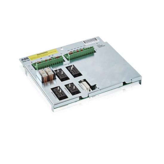
DSQC504 is a connector unit board in ABB industrial automation systems, which is a supporting hardware module for robots or controllers. It is mainly used for signal conversion and electrical connection management. Its core function is to provide standardized interface extensions for industrial control systems, enabling signal transmission and electrical adaptation between different devices, commonly found in robot controllers, PLC systems, or distributed I/O architectures.
Core features
Multi interface integrated design
Provide multiple electrical interfaces (such as terminal blocks and cable interfaces), supporting the access and distribution of digital signals (DI/DO) and analog signals (AI/AO).
Compatible with mainstream ABB controllers (such as IRC5 series), it can be combined with DSQC series I/O modules (such as DSQC346B, DSQC509) to build a complete automation control network.
High reliability connection
Adopting anti misconnection design (such as unique interface shape or coding) to avoid system failures caused by wiring errors.
The terminal supports high current loads (such as 24V DC, with a maximum current of 5A) and is suitable for driving actuators such as relays and solenoid valves.
Flexible system expansion
As an intermediate transfer layer, it can distribute the controller’s signals to multiple peripheral devices or aggregate multiple sensor signals to a single controller, simplifying wiring complexity.
Support hot swapping (some models) for easy system maintenance and upgrades, reducing downtime.
Industrial grade protection
Compliant with IP20 protection level, suitable for dust and slight splashing scenarios in industrial environments.
Anti electromagnetic interference (EMC) design ensures stable operation in strong electromagnetic environments, such as near frequency converters.
Typical application scenarios
Robot system integration
In industrial robot workstations, DSQC504 is used to connect robot controllers with end effectors (such as grippers and welding guns), transmitting control signals and feedback signals. For example:
Connect sensors (such as force sensors) to the controller to achieve force control feedback for robot operations.
Transfer the electromagnetic valve signal to control the opening and closing action of the pneumatic fixture.
Electrical cabinet for automated production line
As the signal center of the electrical cabinet in the production line, it distributes the control signals of the PLC to the executing equipment at each workstation (such as motor drivers and indicator lights), while collecting sensor signals (such as proximity switches and encoders) and transmitting them back to the PLC.
Typical scenario: In the automobile assembly line, the signals from the vehicle positioning sensor and the robotic arm controller are transferred to ensure assembly accuracy.
Process control equipment connection
In the control systems of the chemical and food industries, it is used to connect distributed I/O modules with field instruments (such as temperature transmitters and pressure switches) to achieve centralized processing of analog signals.
Support redundant connections (such as dual power inputs) to enhance the reliability of critical processes.
Testing and Development Platform
In laboratory or R&D scenarios, as a flexible signal testing interface, it facilitates engineers to access temporary sensors or debug equipment, accelerating system development and verification.
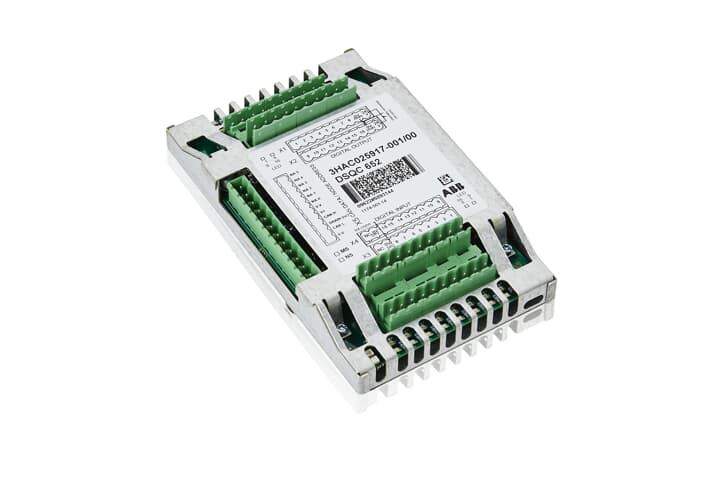
DSQC509 is a modular I/O module under ABB, suitable for the industrial automation field, and is a key component of robot controllers or industrial control systems. Its design focuses on high-precision signal processing and system integration flexibility, commonly used in scenarios such as robot arms, automated production lines, and process control equipment. It can achieve the acquisition, processing, and control output of digital/analog signals, supporting efficient collaboration with upper computers, sensors, and actuators.
Core functional characteristics
Multi type signal processing
Supports digital input/output (DI/DO): adapts to switch signals (such as button and relay status), with a response speed of milliseconds, used for logical control of equipment start stop, safety interlock, etc.
Supports analog input/output (AI/AO): can connect continuous signals such as temperature, pressure, current, etc. (such as 4-20mA, 0-10V), built-in high-precision ADC/DAC conversion module, with an accuracy of ± 0.1% FS.
Pulse signal processing: Supports encoder pulse counting, suitable for motor speed monitoring or position feedback.
Modularity and Scalability
Adopting standardized guide rail installation, supporting parallel combination of multiple modules, and expanding the number of I/O points (such as 16 point DI/16 point DO or 8-point AI/8-point AO configurations).
Compatible with mainstream ABB controllers such as IRC5 and AC800M, and enables fast data exchange through bus interfaces such as PROFIBUS DP and EtherCAT.
High reliability design
Electrical isolation: Optoelectronic isolation technology is used between channels, which has strong anti-interference ability and is suitable for strong electromagnetic environments (such as steel and chemical industries).
Fault diagnosis: Built in self diagnostic function, supports channel level fault detection (such as disconnection, short circuit), and provides real-time feedback on status (power supply, communication, fault) through LED indicator lights.
Wide temperature operation: The working temperature range is -20 ° C to+60 ° C, suitable for harsh industrial environments.
Communication and integration capabilities
Supports PROFIBUS DP V1 (maximum transmission rate of 12 Mbit/s), Ethernet/IP or Modbus TCP, seamlessly integrated into industrial Ethernet or fieldbus networks.
Support seamless integration with ABB robot systems (such as RobotStudio) to achieve collaborative control between robots and peripheral devices (such as fixture opening and closing, sensor triggering).
Typical technical parameters
Structural form: Modular (rail mounted)
I/O points: 16 digital quantities+8 analog quantities (expandable)
Used for signal control of end tools of industrial robots, such as welding guns and grippers, to achieve tool status feedback and action triggering.
Typical case: In the automotive welding production line, DSQC509 collects sensor signals to control the lifting of the welding gun and adjust the welding parameters.
Automatic production line
Connect conveyor belts, detection equipment, and actuators to achieve logical control of material sorting and assembly processes.
For example, in an electronic assembly line, the material arrival signal is monitored through digital input to drive the robotic arm to complete component picking and placement.
Process Control and Monitoring
In the chemical, food and beverage industries, it is used to monitor analog signals such as temperature and pressure, and output control instructions to regulate equipment such as valves and pumps.
Support integration with DCS (Distributed Control System) to achieve real-time closed-loop control of process parameters.
ABB DSQC346B is an advanced modular I/O system that plays a critical role in the field of industrial automation. It has become an ideal choice for many industrial enterprises to build efficient automation control systems due to its excellent performance, high flexibility, and outstanding reliability. This system can achieve precise acquisition and control of various industrial signals, effectively improving the automation level and stability of the production process.
Function characteristics
1. Diversified I/O interfaces
The DSQC346B is equipped with a wide range of I/O interfaces, including digital input/output and analog input/output interfaces. The digital interface can easily connect digital signal devices such as buttons and relays, quickly and accurately sensing device status and executing control instructions. For example, in an automated production line, it can quickly respond to various switch signals and control the start stop and operation of equipment. Analog interfaces are suitable for connecting sensors, industrial operation interfaces, etc. They can accurately convert received analog signals into digital values, meeting the collection and processing needs of continuous changing signals such as temperature, pressure, flow, etc. They are widely used in scenarios that require precise process control.
2. Efficient data processing capability
It has a powerful data processing core internally, capable of processing large amounts of I/O data at extremely high speeds. With a processing speed of up to 50MHz, the system can ensure timely response to various input signals in complex industrial environments and quickly generate accurate control outputs. Whether it is high-speed automated equipment or large-scale data collection tasks, it can handle them with ease, effectively improving the real-time performance and response speed of the entire control system.
3. Flexible module combinations
The system adopts a modular design concept, and users can freely choose different types and quantities of I/O modules to combine according to their actual application needs. This flexible configuration method enables the system to perfectly adapt to various complex and ever-changing industrial automation scenarios. Whether it is simple single machine automation control or large-scale factory automation production lines, the best control effect can be achieved through reasonable module combinations, while reducing system construction costs.
Reliable communication function
DSQC346B supports multiple communication protocols, such as PROFIBUS DP, Ethernet, etc. Among them, the PROFIBUS DP transmission rate can be extended to 12 Mbit/s, specifically optimized for interaction with remote I/O, drive, and motor control devices, ensuring fast and stable data transmission in industrial networks. Through Ethernet interface, the system can easily exchange and share data with the upper computer and other intelligent devices, achieving factory level information management and collaborative control, laying a solid foundation for building an intelligent factory.
Technical Parameter
Structural form: modular
LD instruction processor: hard PLC
I/O points: 3
Working voltage: 24V
Output frequency: 10/100 Mbps
Processing speed: 50MHz
Program capacity: 16MB
Data capacity: 256MB
Environmental temperature: 0 to 60 degrees Celsius
Environmental humidity: 5 to 95%, non condensing
Product certification: CE
Weight: 0.2 kilograms
Dimensions: 114mm, 257mm, 80mm
Application scenarios
1. Industrial automation production line
In industrial automation production lines such as automobile manufacturing and electronic equipment production, DSQC346B can collect real-time operation status signals of various equipment on the production line, such as equipment start stop, position detection, etc., and accurately control the operation of the equipment according to preset programs, realizing a series of automated operations such as material handling, processing, assembly, etc., effectively improving production efficiency and product quality, and reducing labor costs.
2. Process control field
In the process control industries such as chemical, power, and metallurgy, this system can accurately collect and control key process parameters such as temperature, pressure, and flow rate. For example, in chemical production, real-time monitoring and adjustment of temperature and pressure inside the reaction vessel ensure that the chemical reaction proceeds under optimal conditions, improve product yield and quality, and ensure the safe and stable operation of the production process.
3. Intelligent warehousing and logistics
In the intelligent warehousing and logistics system, DSQC346B can collaborate with automated three-dimensional warehouses, stackers, conveyors, and other equipment. By collecting information such as the location of goods and the operating status of equipment, automatic storage, retrieval, and handling of goods can be achieved, improving the operational efficiency of warehousing and logistics, and reducing errors during the storage and transportation of goods.
ABB 3HAB8859-1/03A is a high-performance control module designed specifically for industrial automation systems. It has precise control capabilities and can operate stably in complex industrial environments, providing reliable support for various industrial applications and occupying a key position in the process of industrial automation.
Brand background
ABB, as a globally renowned electrical and automation technology enterprise, has a history of over 130 years and operates in more than 100 countries, achieving excellence in various fields such as energy management, industrial automation, and motion control. It adheres to the concept of innovation, relies on profound technological accumulation and global service network, and continuously launches high-quality products. The 3HAB8859-1/03A module is the crystallization of ABB’s technological strength and innovative spirit.
Specification parameters
parameter
details
Input Voltage
Adapt to a wide voltage range, customized according to actual working conditions to ensure normal operation in different power environments
protection grade
Reaching IP20, dustproof, providing basic protection for internal circuits
size
Compact design, conducive to installation and integration in limited space, reducing equipment space occupation
weight
Lightweight, convenient for transportation and installation operations
communication interface
Equipped with multiple interfaces, such as RJ45 Ethernet ports for controlling network connections and supporting high-speed data transmission; Serial ports are used to connect configuration tools and adapt to different communication requirements
Core functions
Precise control signal output: Through precise engineering design, it can continuously and accurately output control signals, accurately regulate motor speed, equipment operating status, etc., improve the overall control accuracy and stability of the system, and meet the strict requirements for control accuracy in industrial scenarios.
Multi protocol compatibility: Compatible with multiple industrial automation protocols, such as common Modbus, Profibus, etc., facilitating integration in different automation system architectures, enabling data exchange and collaborative work with other devices and systems, enhancing system compatibility and scalability.
Real time monitoring and feedback: Real time monitoring of the working status and operating parameters of the controlled equipment, such as temperature, current, voltage, etc. Once the parameters are abnormal, they are quickly fed back to the control system, triggering corresponding protective actions or alarm prompts to ensure the safe operation of the equipment and reduce the risk of faults.
Working principle
This module is based on a built-in microprocessor and synchronizes system time accurately through a real-time clock. The microprocessor processes and analyzes the preset program and received external signals to generate control instructions. The instructions are transmitted to the corresponding output ports through the data bus and converted into driving signals to control external devices. For example, in the motor control scenario, the module receives a speed setting signal, and after internal algorithm calculation, outputs a PWM (Pulse Width Modulation) signal to adjust the motor speed. At the same time, it uses sensor feedback signals to adjust the control strategy in real time to ensure stable operation of the motor.
Key advantages
High reliability: The sturdy design can withstand harsh industrial environments such as high temperature, high humidity, strong electromagnetic interference, etc., ensuring long-term stable operation, reducing equipment failure downtime, and improving production efficiency.
Easy to integrate: Compact and lightweight, with design that fully considers integration requirements in terms of size, interface, communication protocol, etc., it can easily integrate into existing industrial automation systems without significant modifications, reducing system upgrade costs and difficulties.
Efficient and energy-saving: precise control functions prevent equipment from running excessively or idling, optimize energy utilization, achieve energy conservation and consumption reduction, conform to the trend of green industry development, and reduce enterprise operating costs.
Precautions
Installation environment: It should be installed in a dry, well ventilated, and temperature appropriate place, avoiding direct sunlight and strong corrosive gas environment to prevent module damage and affect performance and lifespan.
Electrical connection: Strictly follow the instructions for electrical connection, ensure that the wiring is firm and correct, prevent short circuits, open circuits and other problems, and ensure the normal operation of the module and the safety of personnel and equipment.
Software configuration: When configuring software parameters, professional personnel are required to operate and set them reasonably according to actual application needs to avoid abnormal device operation caused by parameter errors.
Similar model supplement
3HAB8101-19 DSQC545A: ABB’s high-performance servo drive focuses on the field of motor servo control, with stronger driving capabilities and more precise position control functions. It is suitable for industrial robots, CNC machine tools, and other equipment that require extremely high motor motion control accuracy and response speed.
PFSK164 3BSE021180R1: ABB signal concentrator board module, mainly used for signal centralized processing and transmission, plays a key role in large-scale data acquisition and monitoring systems, can efficiently integrate dispersed signals, achieve centralized management and transmission, and has different functional focuses from 3HAB8859-1/03A, but can work collaboratively in complex automation systems.
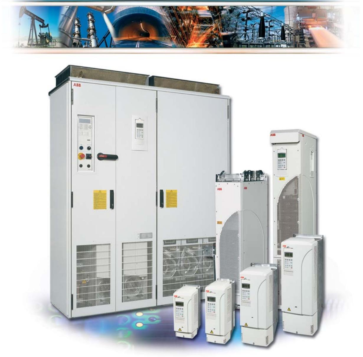
Scope of application: The firmware manual for the standard control program of ACS800 frequency converter is suitable for motor drive control in the field of industrial automation, supporting multiple control modes and communication protocols.
Core functions: including startup configuration, control panel operation, parameter setting, fault diagnosis, communication interface, and various application macros (such as factory macros, PID control macros, torque control macros, etc.).
Startup and control mode
Start the process
Startup Wizard: Guide users to complete motor parameter settings (such as voltage, current, frequency, etc.) and identification run (ID Run), supporting both standard and simplified identification modes to ensure motor control accuracy.
Basic startup: Manually input parameters, suitable for quick configuration scenarios without the need for a wizard.
control model
Local control: Directly operated through the control panel, supporting start, stop, steering, and speed settings.
External control: Receive commands through digital/analog inputs or fieldbus (such as PROFIBUS, Modbus), supporting dual control switching between EXT1 and EXT2.
Core functional modules
Program Function
Given signal processing: supports multi-source given signals such as analog input, digital input, fieldbus, etc., and can combine given signals through mathematical operations (such as addition, subtraction, multiplication, division, and taking the maximum value).
Torque control: Suitable for scenarios that require precise torque output, such as elevators and conveyor belts.
Braking control: Supports DC brake, magnetic flux brake, and mechanical brake, with configurable braking delay and torque threshold.
Application Macro Program
Factory macro: default mode, suitable for general speed control scenarios, supports 3 constant speed options.
PID control macro: used for process control (such as pressure and flow closed-loop), integrating sleep function to optimize energy consumption.
Torque control macro: directly controls motor torque, supports switching with speed control mode.
User macro: allows storage of two sets of custom parameters, facilitating quick switching between different motors or operating conditions.
Communication and Interface
Fieldbus support: compatible with protocols such as PROFIBUS, Modbus RTU/TCP, PROFINET, etc., and supports redundant communication configurations.
I/O expansion module: can connect digital/analog expansion modules, expand input and output channels, support motor temperature measurement, encoder interface, etc.
Parameters and actual signals
Parameter group division:
Startup data (99 sets): motor nameplate parameters, control mode, identification of operating configuration.
Given options (11 groups): Define the source of speed/torque given (such as analog input, fieldbus).
Limit values (20 sets): Setting operating limits such as speed, current, torque, etc.
Fault function (30 sets): Protection parameters for overcurrent, overvoltage, underload, etc., supporting automatic reset and alarm threshold setting.
Actual signal monitoring: Real time display of speed, current, torque, DC bus voltage, etc., supporting custom display combinations and filtering processing.
Fault diagnosis and maintenance
Fault codes and reset
Locate faults through control panel LED indicators or fault codes (such as overcurrent, overheating, communication interruption), and support manual or automatic reset (parameter configuration required).
Fault records store the last 6 events, including timestamps and fault types, to assist in quick troubleshooting.
Maintenance suggestions
Regularly check the matching of motor parameters, encoder connections, and the operating status of the cooling fan.
The communication module should pay attention to grounding and anti-interference, and avoid parallel wiring of high-voltage lines and signal lines.
Safety and Standards
Electrical safety: Ensure that grounding complies with NEC standards, avoid modifying parameters with motors, and prevent accidental start-up.
Electromagnetic compatibility (EMC): Sensor cables need to be shielded and grounded at one end, and isolated from high-voltage lines.
Compliance certification: Complies with IEC standards and supports explosion-proof applications in hazardous environments (requires corresponding module configuration).
Use MNavigate to re download the application to the CF card and ensure that the download process is interference free.
Network communication failure
1. Unable to access MLink() through web interface or MNavigate
Possible reasons:
IP address configuration error or network parameter conflict.
MLink is not powered on or there is a hardware malfunction (such as LED7 not lighting up).
The web server is not activated or the network link is interrupted.
resolvent:
Check the power and hardware status: Confirm that LED7 (power indicator light) is always on and there are no other fault LED alarms.
Verify network configuration:
Check whether the LAN2 IP address and subnet mask are correct through MNavigate (default: 192.168.200.100/24).
Use the ping command to test connectivity (such as ping 192.168.200.100), and if it fails, check the network cable connection or switch status.
Activate the web server: Confirm through MNavigate that the web service is enabled and restart MLink.
2. Communication with MControl failed (unable to download configuration) ()
Possible reasons:
The internal bus (Switchgear Bus) connection is loose or the terminal resistance is not configured.
MControl is not online or bus communication is interrupted (such as MControl’s LED flashing indicating offline).
resolvent:
Check physical connections: Ensure that the blue Sub-D 9-pin interface is secure, the bus cable shielding layer is well grounded, and the terminal resistance meets the topology requirements.
Activate MControl: Set MControl to “online” status through MNavigate and confirm that its LED status is normal.
Time synchronization failure
1. Inaccurate or missing timestamp ()
Possible reasons:
NTP server address error or network unreachable.
MLink internal RTC battery failure or no time synchronization mode configured.
resolvent:
Configure NTP server:
Set the correct NTP server IP address (such as 192.168.200. xxx) through MNavigate to ensure that it is on the same subnet as MLink.
If using MLink itself as an NTP server, it is necessary to manually set the time zone and time (through the web interface).
Check RTC function: Replace the CF card or contact technical support to confirm the status of the hardware RTC module.
Redundant system failure
1. Main/backup MLink synchronization failed ()
Possible reasons:
Redundant cables are not connected or damaged.
The configuration of the primary and backup modules is inconsistent (such as IP address conflicts).
resolvent:
Physical connection check: Confirm that the redundant cable (Serial 1 interface) is correctly connected and that the plugs at both ends are not loose.
Synchronous configuration: Generate redundant reports through MNavigate to ensure that the IP addresses and protocol parameters of the primary and backup modules are completely consistent.
CF card related faults
1. CF card cannot be recognized or configuration is lost ()
Possible reasons:
The CF card is not inserted correctly or has poor contact.
The card file is damaged (such as missing XML configuration file).
resolvent:
Re insert and unplug the CF card: Ensure that the card is oriented correctly (with the metal contacts facing upwards), and close the metal shield after insertion.
Rewrite configuration: Use a card reader to rewrite the configuration file generated by MNavigate to the CF card, avoiding interruptions in the download process.
General solution process
Restart MLink: Clear temporary software faults by pressing the front panel reset button or restarting after power failure.
Restore default settings: Use MNavigate to load factory default parameters such as IP address and subnet mask.
Hardware replacement test: If there is suspicion of hardware failure (such as continuous LED alarm), replace the CF card or MLink module and reconfigure.
This document is the user manual (system version V7.0) for the MLink interface module (model 1TGE120021) in the ABB MNS iS system. It mainly introduces its hardware features, software modules, communication interfaces, and operation and maintenance. The following is a detailed summary:
Product positioning and target users
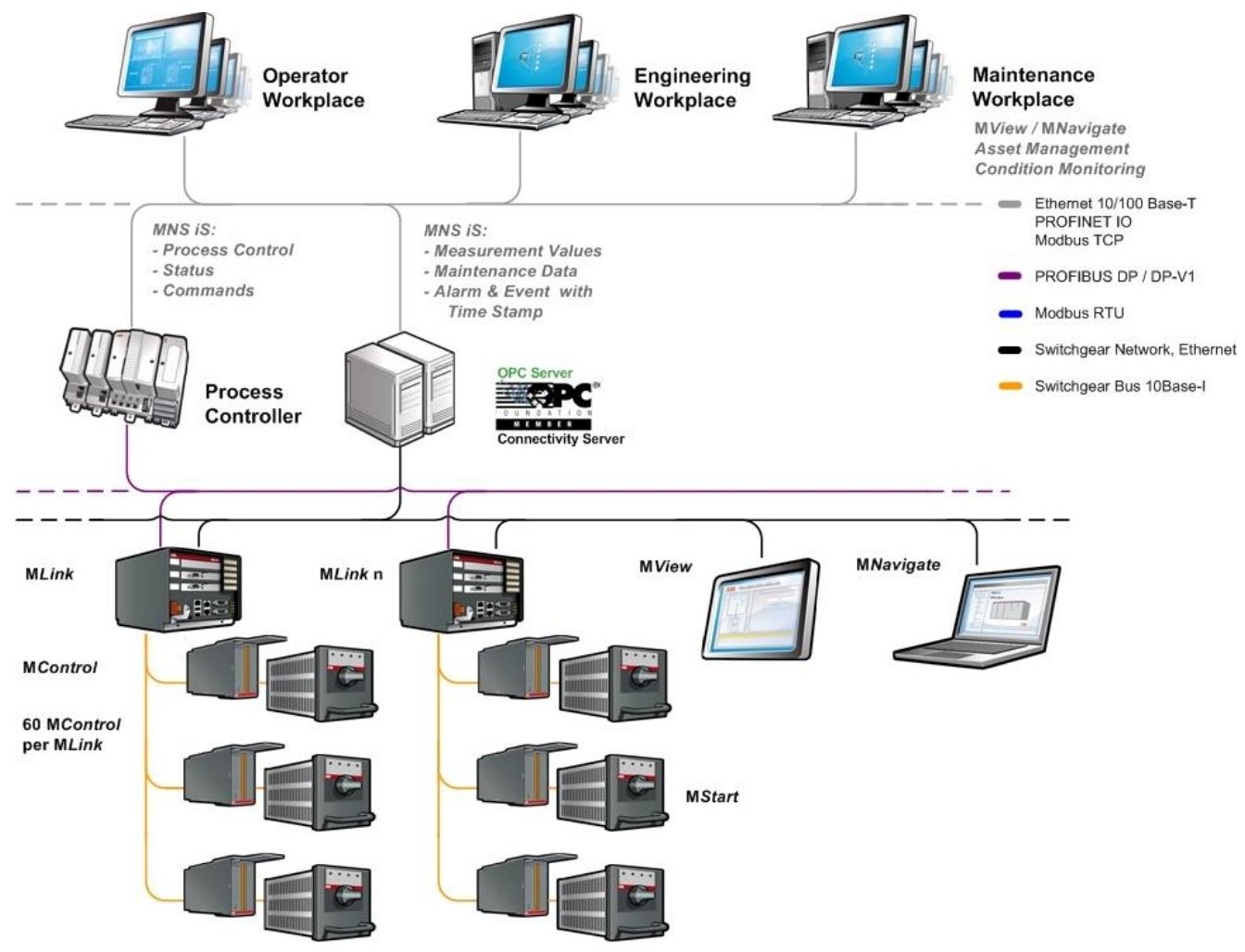
Positioning: MLink is an industrial PC module that serves as the core communication interface for MNS iS systems, connecting internal motor control units (MControl) and external control systems (such as DCS, PLC), supporting data exchange, status monitoring, and system integration.
Target users: System engineers, control engineers, familiar with fieldbus (such as PROFIBUS, Modbus) and industrial communication basics.
Power supply: 24V DC (19-31V DC), typical power consumption 800mA
Size: 140 × 160 × 165mm, weight 2.5kg
Working temperature: 0 ° C~55 ° C, protection level IP51
Mean Time Between Failures (MTBF): 46 years (40 ° C environment)
2. Interface and Connection
Front board interface:
Internal communication: Blue Sub-D 9-pin interface (Switchgear Bus), connected to MControl, supports redundant configuration.
External communication:
PROFIBUS DP: Black interface with communication status LED (yellow running, green ready).
Modbus RTU: RS485 interface (Serial 2).
Ethernet (LAN1/LAN2): LAN1 is used for Modbus TCP or PROFINET, while LAN2 connects to the control network (10/100 Base-T).
Other interfaces: reset button, CF card slot (supporting hot swappable protection), power terminal (+24V/GND).
Software modules and functions
Core module:
Web Server: Access the MView interface through a browser to monitor system status (activation required).
OPC Server: Supports data acquisition (DA) and alarm events (AE), requiring separate software installation.
Fieldbus module: Implement protocol conversion with DCS, depending on hardware model (such as PROFIBUS/Modbus).
Time synchronization: Supports NTP protocol and can provide timestamps through GPS or internal RTC to ensure event recording accuracy.
Redundancy support: Dual MLink modules are synchronized through redundant cables, with primary and backup switching to ensure system reliability.
Communication network configuration
1. Internal network (Switchgear Bus)
Function: Connect MLink and MControl (up to 60), the cable shielding layer needs to be grounded at both ends, and supports bus topology and terminal resistance configuration.
Features: Plug and play, no additional configuration required, communication status monitored through LED (Swg Bus Rx/Tx).
2. Switchgear Control Network
Architecture: Based on standard Ethernet (LAN2), supporting direct connection (cross cable) or connecting multiple MLinks, MView (human-machine interface), and engineering tools (MNavigate) through switches.
Security requirements: If you need to access the factory network, you need to configure a firewall and router to prevent unauthorized access.
Time synchronization scheme:
Option 1: Third party NTP servers (such as switches with GPS) provide time signals.
Option 2: MLink acts as an NTP server to synchronize time with other devices (with a built-in RTC that can cache for 3 hours).
Operation and maintenance
1. Initial setup
Tool: Use MNavigate software to configure parameters such as IP address, subnet mask, time server, etc. The parameters need to be written to the CF card and restarted to take effect.
Default value:
LAN2 IP:192.168.200.100,LAN1 IP:192.168.100.100
DHCP is not supported, network parameters need to be manually configured.
2. Installation steps
Physical installation: Installed in the control cable compartment of the MNS iS cabinet, fixed with metal brackets and supporting quick insertion and removal.
CF card operation: When inserting, pay attention to the direction (mechanical coding to prevent reverse insertion), and the configuration file needs to be written through MNavigate.
3. Fault diagnosis
LED indicator light: It displays the operating status, communication faults, and redundancy status through 8 LEDs (such as LED2 indicating system faults and LED6 indicating DCS communication activation).
Common problem handling:
Network failure: Check IP configuration, ping test connectivity, and rewrite CF card configuration.
MControl offline: Confirm internal bus connection and MControl online status settings.
Documentation and Compatibility
Related documents: The accompanying manual covers the web interface PROFIBUS、Modbus、 Special content such as redundant configuration.
System compatibility: Only applicable to MNS iS System Release 7.0, please refer to the latest system guidelines for functional implementation.
Summarize
The MLink module is the communication hub of ABB MNS iS system, which seamlessly integrates motor control with upper level systems in industrial environments through flexible protocol support and reliable hardware design. Its core advantages include multi protocol compatibility, high time synchronization accuracy, and strong redundancy reliability, making it suitable for automation control systems that require high real-time performance and stability. Operation and maintenance rely on the specialized tool MNavigate, and attention should be paid to network configuration specifications and hardware installation details.