Core function: Real time monitoring of turbine speed and adjustment of inputs (such as steam and fuel) through mechanical or electro-hydraulic mechanisms to maintain equipment operation within the set speed range, prevent overspeed or speed fluctuations, and ensure system stability.
Application scenarios: Suitable for power equipment such as steam turbines and gas turbines, commonly used in industrial fields such as power generation, petrochemicals, and mechanical drives.
Performance characteristics: Suitable for higher torque requirements, higher adjustment accuracy, part numbers such as TG611-17, Screw, 2400 rpm, CW, ATEX, w/OTD: 8516-186.
2. Key parameters
Overspeed Protection (OTD): Some models integrate overspeed trip devices, which automatically trigger shutdown when the speed exceeds a threshold, enhancing system safety (such as part numbers 8516-175 to 8516-191 all have OTD).
Certification and Environment: Supports ATEX certification, suitable for Zone 2 hazardous areas, resistant to vibration and high temperature.
Structure and Working Principle
Mechanical structure: Using screws or levers to drive, sensing changes in rotational speed through centrifugal force, and driving hydraulic actuators to adjust valve opening.
Closed loop control: The speed sensor (such as a magnetic pickup) provides real-time feedback signals, and the speed controller outputs adjustment signals based on deviations, forming a “monitoring adjustment feedback” loop.
Accessories and System Integration
Conversion kit:
TG to TG611 conversion kit (part number: 8516-174), used for upgrading and replacing old models of TG speed controllers to reduce renovation costs.
Actuator matching:
It can be paired with Woodward TGE turbine actuators (such as TGE13, TGE17) or VariStroke actuators to achieve “governor actuator” coordinated control.
Monitoring and Communication:
Connect to industrial networks through the MicroNet system or Flex500 platform, and support remote configuration of parameters (such as speed set points and sag coefficients) using GAP software.
Spare parts and maintenance:
Seals, springs, drive shafts and other spare parts (refer to the spare parts list in the product catalog) to ensure long-term operational reliability.
Advantages and Characteristics
High precision adjustment: The droop characteristic can be adjusted to meet the load distribution requirements of single machine operation or multi machine parallel connection.
Security protection: Integrated OTD overspeed trip device to reduce the risk of equipment damage caused by overspeed.
Strong compatibility: Compatible with other Woodward products such as ProTech overspeed protection devices and UG series speed controllers, making it easy to build a complete control system.
Environmental adaptability: ATEX certification supports applications in hazardous areas, with durable mechanical structures suitable for harsh industrial conditions.
Application scenarios
Power generation field: Stable speed control of steam turbine generator units to ensure constant grid frequency.
Petrochemical industry: Speed regulation of gas turbine driven compressors, pumps and other equipment to adapt to changes in process loads.
Mechanical drive: drives industrial machinery such as fans and rolling mills to maintain speed to ensure production efficiency.
Core function: By real-time monitoring of turbine speed and adjusting fuel/steam input, maintain equipment operation within the set speed range, ensure system stability, and prevent overspeed or speed fluctuations.
Working principle: Utilizing centrifugal force or electronic sensors to sense changes in rotational speed, driving actuators through mechanical or electro-hydraulic mechanisms, adjusting valve opening, and achieving closed-loop control.
Main models and features
1. TG13 series
Application scenario: Suitable for medium and low-speed turbine systems, supporting ATEX certification, and adaptable to hazardous environments.
Model features:
TG13 Screw (screw type):
Speed range: 2400 rpm, 4000 rpm, 6000 rpm, rotation direction divided into CW (clockwise) and CCW (counterclockwise).
The rated speed droop (Droop) can be adjusted, for example, at @ 2 ° Droop, the rated speed is 1950 rpm or 2010 rpm (part numbers: 9904-814 to 9904-828).
TG13 Lever:
The structure is more suitable for space constrained scenarios, with other parameters similar to screw types (such as part numbers 9904-817, 9904-819, etc.).
2. TG17 series
Performance Upgrade: Suitable for higher torque demands, with a speed range that overlaps with TG13, but with stronger adjustment accuracy and stability.
Model example:
TG17 Screw: 2400 rpm, 4000 rpm, 6000 rpm specifications, supporting ATEX certification, part numbers such as 9904-800 (2400 rpm, CCW, @ 2 ° Droop=1950 rpm), 9904-803 (4000 rpm, CCW, @ 2 ° Droop=4035 rpm), etc.
TG17 Lever: such as 9904-808 (2400 rpm, CCW, @ 2 ° Droop=2010 rpm), supports different droop characteristic configurations.
3. TG611 series
Upgrade and Conversion: TG to TG611 Conversion Kit (Part Number: 8516-174), compatible with old system upgrades; The TG611-13/17 model supports overspeed trip device (OTD) and enhances safety protection (part numbers: 8516-175 to 8516-191).
Core parameters and configuration
Speed range: covering 2400 rpm to 6000 rpm, customizable according to turbine model.
Rotation direction: CW (clockwise) or CCW (counterclockwise), which should match the rotation direction of the turbine shaft.
Droop characteristic: Typical value of 2%, adjustable, used for load distribution when multiple machines are connected in parallel.
Certification and environmental adaptability: Supports ATEX certification, suitable for Zone 2 hazardous areas, some models are vibration resistant and high temperature resistant.
Accessories and System Integration
Actuator matching: can be paired with TGE turbine actuators (such as TGE13, TGE17, part numbers 9904-110 to 9904-115) or VariStroke actuators to form a “governor+actuator” closed-loop control chain.
Monitoring and Communication: Remote monitoring is achieved through the MicroNet system or Flex500 platform, and GAP software programming is supported to adjust control parameters.
Maintenance kit: includes spare parts such as seals, springs, etc. (refer to the spare parts list in the “Electro hydraulic Governor and actuator” section) to ensure long-term reliable operation.
Application scenarios
Industrial power generation: Stable speed control of steam turbine generator units to ensure constant grid frequency.
Mechanical drive: When driving equipment such as compressors and pumps, maintain the speed to match the load demand.
Petroleum and Chemical Industry: Speed regulation of gas turbines in gas pipelines and refining facilities to adapt to harsh working conditions.
Advantages and Characteristics
Reliability: The mechanical structure is mature, and some models support redundant design to reduce the risk of downtime due to failures.
Flexibility: It can adapt to different working conditions by adjusting the sag coefficient and speed setting point, and supports on-site manual or remote electronic adjustment.
Compatibility: Seamless integration with other Woodward control products, such as ProTech overspeed protection devices, to build a complete safety system.
Features: Supports redundant configuration to ensure system power stability, and some models (such as MicroNet TMR PS) are compatible with triple systems.
3. CPU Modules
model:
5200CPU MicroNet TMR (part numbers: 5466-1347, 5466-1247): Supports TMR redundancy and is suitable for high reliability scenarios.
MicroNet Plus P1020 CPU (part number: 5466-1511): A standard CPU that supports basic control logic processing.
Function: Execute control algorithms, data processing, and system coordination, supporting the expansion of rack modules.
4. Communication Modules
Type:
RTN to CAN Gateway (part number: 8200-1250): Implement RTN (Real Time Network) and CAN protocol conversion.
Remote RTN (MicroNet Plus) (part numbers: 5466-1146, 5466-1246): Supports remote real-time network communication and has network security capabilities.
SIO Module (part numbers: 5466-5006, 5466-5007): Provides serial communication interfaces such as RS232, RS422, RS485, etc.
Function: Supports multiple industrial communication protocols, enabling data exchange and remote monitoring between systems.
5. Input/Output Modules
Input module:
Speed sensor module (part numbers: 5466-5000 to 5466-5003): supports 4-channel magneto electric sensors (MPU) or eddy current probes for speed monitoring.
The actuator driver module (part numbers: 5501-1428 to 5501-1432) supports ± 12.25 mA to ± 245 mA output and drives hydraulic or electric actuators.
Hybrid I/O module:
High density combination I/O (part numbers: 5466-1105, 5466-1115): Integrated speed input, analog input/output, suitable for compact systems.
Discrete I/O module (part numbers: 5466-1050, 5466-1158): Supports 48 inputs/24 outputs and is compatible with different voltage levels.
6. Other functional modules
LINKnet HT Modules: such as RTD input (8200-1200), thermocouple input (8200-1201), 4-20 mA input/output (8200-1202, 8200-1203), etc., used for distributed I/O expansion.
RTCnet Modules: Similar in functionality to LINKnet HT, suitable for different network protocols (part numbers: 8200-1100 to 8200-1105).
Dataforth I/O: Supports signal conversion for thermocouples, RTDs, 4-20 mA, etc. (part numbers: 1784-1028, 1784-655, etc.).
System features and advantages
Modularity and Scalability
Each module can be independently plugged and unplugged, supporting flexible configuration of I/O points, communication interfaces, and power types according to requirements, adapting to different scenarios from small devices to large systems.
High reliability design
TMR triple chassis and redundant power modules can reduce the risk of single point of failure and are suitable for industries with high safety requirements such as petroleum and chemical.
Real time performance and compatibility
Supports real-time networking (RTN) and multiple industrial protocols, seamlessly integrating with other Woodward products such as Flex500 and ProTech overspeed protection devices to achieve system level collaborative control.
Standardization and usability
Supporting GAP software programming, supporting graphical logic development, reducing programming difficulty; Provide detailed documentation (such as Product Spec: 03333, Manual: 26166V1) for easy installation and maintenance.
Application scenarios
Industrial turbine control: speed regulation, load sharing, and protection logic execution for steam turbines and gas turbines.
Compressor and power system: anti surge control, flow regulation, and equipment status monitoring.
Power generation and energy management: parallel control of generator sets, load distribution, and grid coordination.
Process automation: closed-loop control of parameters such as pressure, temperature, and flow in chemical and petroleum equipment.
Typical Configuration and Accessories
Hardware kit:
MicroNet TMR Hardware Kit (part numbers: 8262-1145 to 8262-1150): includes core modules such as chassis, power supply, CPU, etc., and supports triple configuration.
MicroNet Plus Hardware Kit (part numbers: 8262-3183 to 8262-3185): a standard kit suitable for basic control scenarios.
Cables and accessories:
Simulate cables (NetCon Analog Cables, part numbers: 5416-346 to 5416-351), Ethernet cables (part numbers: 5417-391 to 5417-396), etc., to ensure electrical connections between modules.
Summary
MicroNet ™ System Modules provides flexible and reliable solutions for industrial control through highly modular design, especially suitable for turbines, compressors, and energy systems that require high scalability and real-time performance. Users can combine different modules according to their specific needs, and combine them with Woodward software and other hardware to build customized control solutions.
The Flex500 platform is a modular and programmable electronic controller that can flexibly adapt to the control needs of different industrial turbine equipment. It supports multiple software cores and communication protocols, has high reliability and scalability, and is commonly used in speed control, load sharing, process control, and other scenarios.
Core components and functions
Hardware specifications and models
Installation method and power type:
Front panel installation: Supports LVDC and HVAC/DC power supplies, such as Flex500 (front panel installation, LVDC, OCP) (part number: 8200-1343), Flex500 (front panel installation, HVAC/DC, OCP) (part number: 8200-1344).
Rear panel installation: Supports LVDC, HVAC/DC power supply and Zone 2 hazardous area configuration, such as Flex500 (rear panel installation, LVDC, Zone-2) (part number: 8200-1355).
Core functions: Integrated processor, input/output (I/O) module, communication interface, supporting real-time control and data processing.
Software and Programming Support
GAP software programming: Customize programming through Woodward’s Graphic Application Program (GAP), supporting logic development for MicroNet and Atlas controllers.
Core Source License: such as CSM -505XT Core Source License (part number: 8447-5006), CSM – Vertex Core Source License (part number: 8447-5008), which allows users to run specific control algorithms on Flex500.
Communication and Expansion Module
LINKnet HT and RTCnet modules: support distributed I/O expansion, such as RTD input, thermocouple input, 4-20 mA signal processing, etc. (refer to the module list in the “Electronic Control” section).
Network compatibility: Can connect to MicroNet systems, supports communication protocols such as CANopen and Ethernet, and adapts to complex industrial network architectures.
Application area
Industrial turbine control: used for speed regulation, load sharing, and protection functions of steam turbines and gas turbines.
Compressor control: In conjunction with Vertex controllers and other equipment, achieve anti surge control and operational optimization of the compressor.
Process control: supports industrial process automation scenarios such as air/fuel ratio control and pressure regulation.
Accessories and Documents
Auxiliary module: Can be paired with LinkNet HT analog/digital module and RemoteView software (license part number: 8928-5311) to achieve remote monitoring.
Document reference: The product specification sheet (such as Product Spec: 03433) and user manual (Manual: 26838) provide installation, programming, and maintenance guidance.
Advantage
Flexibility: Modular design supports configuring I/O modules and communication interfaces according to requirements.
Reliability: Suitable for industrial environments and supports installation in hazardous areas such as Zone 2.
Compatibility: Seamless integration with other Woodward products such as 505 controllers and MicroNet systems, reducing system complexity.
Characteristic
Modular design, strong adaptability
Flexible hardware configuration
Support front/back panel installation, adapt to different device layouts, optional LVDC, HVAC/DC power supplies, and Zone 2 hazardous area models (such as 8200-1355) to meet diverse environmental needs.
Expandable I/O modules such as LINKnet HT and RTCnet, flexibly adding functions such as RTD input, thermocouple, 4-20 mA signal processing, etc., to adapt to complex control scenarios.
Software core compatibility
Through CSM core source licenses (such as 505XT, Vertex core), it supports running different control algorithms and can adapt to the control logic of different devices such as steam turbines and compressors without the need to replace hardware.
High performance and reliability
Real time control capability
Integrated high-efficiency processor, supporting fast data processing and real-time response, suitable for industrial turbine systems sensitive to speed and load changes.
Industrial grade durability
The design meets the requirements of industrial environments, and some models support installation in hazardous areas (Zone 2), with anti vibration, high temperature resistance, and reduced risk of failure.
Communication and integration advantages
Multi protocol compatibility
Supports communication protocols such as CANopen and Ethernet, and can seamlessly connect with MicroNet systems and remote monitoring software (such as RemoteView, license 8928-5311) to achieve system level data exchange and remote operation and maintenance.
Integrate with Woodward ecosystem
Can be paired with GAP software, ProTech overspeed protection device, VariStroke actuator and other products to build a full chain control solution and reduce integration complexity.
Development and maintenance convenience
GAP programming flexibility
Using the graphical programming tool GAP, supporting custom control logic development, compatible with old version program migration, and shortening development cycles.
Standardized documentation and support
Provide detailed product specifications (03433) and manuals (26838), along with supporting technical support, for easy installation, debugging, and troubleshooting.
Cost and scalability advantages
Reduce hardware costs
Modular design avoids redundant procurement of dedicated controllers, adapts to different scenarios through software configuration, and reduces hardware investment.
Long term scalability
Support firmware upgrades and module extensions, adapt to the iterative needs of industrial systems, and protect long-term investments.
WOODWARD 2300E is designed for precise control of engine or turbine speed, while achieving load balancing and distribution among multiple units. The controller adopts a modular design, with good scalability and adaptability, and can be easily integrated into various complex power systems. Its compact structural design not only saves installation space, but also facilitates maintenance and upgrades. Equipped with an intuitive operating interface, allowing operators to conveniently perform parameter settings, status monitoring, and fault diagnosis operations.
Specification parameters
Input power supply: Supports a wide range of power inputs, with common specifications including 120 VAC/DC, 240 VAC, etc. It can be flexibly adapted according to different application scenarios and power infrastructure, ensuring stable operation under various power supply conditions.
Control accuracy: The speed control accuracy is extremely high, reaching ± 0.1% of the rated speed. This enables effective maintenance of the consistency of the speed of each unit during parallel operation of the generator set, ensuring the frequency stability of power output and meeting the strict requirements for power quality in application scenarios. In terms of load sharing, it is possible to achieve load distribution error control within a very small range, usually within ± 1%, to ensure even load distribution among multiple units, avoid overloading of some units, and improve the operational efficiency and reliability of the entire system.
Communication interface: Equipped with a variety of communication interfaces, such as RS485 interface (supporting Modbus RTU protocol), it can easily communicate data with other devices, achieve remote monitoring and parameter adjustment; Simultaneously equipped with Ethernet interface (supporting Modbus TCP protocol), capable of high-speed data exchange with upper computer, distributed control system (DCS), etc., making it easy to integrate into large-scale automation control systems for centralized management and remote operation. Some models also support CANopen interfaces (supporting DS301/DS401 protocols), enhancing compatibility with fieldbus devices and enabling the connection of a wider range of sensors and actuators, enabling more complex control functions.
Display and operation interface: It has a high-resolution graphical human-machine interface (HMI) that can clearly and intuitively display the operating parameters of the engine or turbine, such as speed, load, temperature, pressure, etc. The interface adopts a concise and clear menu driven design, which is easy to operate and comprehend. Even non professionals can quickly get started with various operations. Support for multilingual display function, convenient for users from different regions around the world, greatly improving the product’s versatility and ease of use.
Environmental adaptability parameters: The working temperature range is usually -20 ℃ to+60 ℃, which can adapt to a wide range of industrial environmental temperature changes, and can operate stably in both cold northern regions and hot southern regions. In terms of protection level, the front panel installation model can reach IP54, with a certain degree of dust and water splash resistance, which can effectively prevent dust and water droplets from entering the interior of the equipment and affecting its normal operation; The installation model of the cabin wall is generally IP20, suitable for relatively clean indoor environments. In some special application scenarios, models can also provide sulfur resistant conformal coating options to enhance the product’s corrosion resistance in corrosive gas environments containing sulfur, ensuring long-term reliable operation in harsh industrial environments.
Core functions
Speed control: Adopting adaptive PID algorithm, it can quickly respond to speed changes, with speed tracking and threshold protection to ensure smooth start-up and shutdown.
Load sharing: When multiple units are connected in parallel, the load can be dynamically distributed in proportional, average, and other modes to ensure efficient operation of each unit.
Synchronous grid connection: automatically matching the frequency and phase of the power grid, reducing the instantaneous impact of grid connection, and ensuring the stability of the power system.
Fault protection: Real time monitoring of abnormalities such as overspeed, overtemperature, overload, etc., supporting fault recording and alarm, and timely troubleshooting of hidden dangers.
Advantages and highlights
High precision control: Ensure stable output of speed and load, suitable for scenarios such as data centers and precision manufacturing that require high power stability.
Flexible Expansion: Rich communication interfaces facilitate integration into automation systems such as DCS, and can also meet complex application requirements through module expansion.
High reliability: Industrial grade hardware that adapts to harsh working conditions, supports remote monitoring and maintenance, and reduces downtime.
Precautions
Installation environment: Avoid strong electromagnetic interference, high temperature and humidity, dusty and corrosive gas environment, and ensure good ventilation and heat dissipation.
Power connection: Connect according to specifications. It is recommended to equip voltage regulators in areas with large power fluctuations and regularly check the circuit.
Equipment debugging: Sensors and actuators need to be accurately matched with controllers, and signal transmission should be carefully calibrated during debugging.
Daily maintenance: Regularly update firmware to optimize performance, and quickly troubleshoot faults based on HMI alarm records.
WOODWARD 5009XT is a high-end digital controller designed for industrial steam turbine systems, specifically designed for multivariable control requirements under complex operating conditions. As the core product of Woodward’s industrial turbine control series, it is positioned higher than the basic 2301E-ST and 505 series, focusing on medium to large steam turbine systems that require high reliability, redundant design, and flexible expansion, such as power plant turbines, industrial drive turbine units, etc. The core value of the product lies in achieving precise collaborative control of speed, load, and pressure through modular hardware architecture and advanced control algorithms. It also supports triple redundancy (TMR) configuration, meets SIL level safety requirements, and reduces the risk of critical equipment shutdown.
Specification parameters
Input power supply: Supports multiple commonly used power specifications, such as 120 VAC/DC, 220 VAC, etc., and can be flexibly selected according to actual application scenarios to meet the power supply needs of different industrial environments, with good power compatibility.
Control accuracy: The speed control accuracy is extremely high, reaching ± 0.1% of the rated speed, which can accurately maintain the operating speed of the steam turbine and ensure stable operation of the equipment under various working conditions, providing stable power output for the production process. In terms of load control, a load distribution error of ≤ 1% (when multiple machines are connected in parallel) can achieve efficient collaborative work among multiple steam turbines, optimizing the overall operational efficiency of the system.
Communication Interface: Equipped with a variety of communication interfaces, including Ethernet interface (supporting Modbus TCP protocol), CANopen interface (supporting DS301/DS401 protocol), and RS485 interface (supporting Modbus RTU protocol). These interfaces enable the 5009XT to easily interact and communicate with other devices, making it easy to integrate into the factory’s distributed control system (DCS) or programmable logic controller (PLC) system for remote monitoring, parameter adjustment, and system level automation control.
Display and operation interface: It has an intuitive graphical human-machine interface (HMI), usually with a high-resolution display screen, which can clearly present various operating parameters of the steam turbine, such as speed, temperature, pressure, load, etc. The interface adopts a menu driven design, which is easy to operate. Even non professionals can quickly get started with parameter settings, system monitoring, and fault diagnosis. Supports multilingual display, making it convenient for users from different regions around the world to use.
Environmental adaptability parameters: The working temperature range is usually -20 ℃ to+60 ℃, which can adapt to a wide range of industrial environmental temperature changes, and can operate stably in both cold northern regions and hot southern regions. In terms of protection level, the front panel installation model can reach IP54, with a certain degree of dust and water splash resistance, which can effectively prevent dust and water droplets from entering the interior of the equipment and affecting its normal operation; The installation model of the cabin wall is generally IP20, suitable for relatively clean indoor environments. Some models also offer sulfur resistant conformal coating options to enhance the product’s corrosion resistance in corrosive gas environments containing sulfur, ensuring long-term reliable operation in harsh industrial environments.
Working principle
The operation of the WOODWARD 5009XT steam turbine controller is based on the closed-loop control principle. Through real-time monitoring and feedback of the operating parameters of the steam turbine, the control signal is continuously adjusted to achieve precise control of the steam turbine. The specific work process is as follows:
Parameter monitoring: The controller collects real-time operating parameters of the steam turbine through various sensors connected to the steam turbine system, such as speed sensors, temperature sensors, pressure sensors, vibration sensors, etc. These sensors convert physical quantities into electrical signals and transmit them to the input module of the controller.
Signal processing and comparison: The microprocessor of the controller processes and analyzes the input sensor signals, compares the collected actual operating parameters with the user’s preset target values, and calculates the deviation between the two. For example, in speed control, the actual speed is compared with the preset speed target value to obtain the speed deviation value.
Control algorithm calculation: Based on the calculated deviation value, the controller uses an internal preset control algorithm, such as PID control algorithm, to perform calculation processing. The PID algorithm calculates the corresponding control quantity based on the proportional, integral, and derivative parameters of the deviation, in order to determine the amplitude and direction of the adjustment required for the steam valve opening. For example, if the actual speed is lower than the target speed, the PID algorithm will calculate a control signal to increase the opening of the steam valve to increase the steam flow into the turbine, thereby increasing the speed; On the contrary, if the actual speed is higher than the target speed, calculate the signal to reduce the valve opening.
Control signal output: The control quantity obtained through control algorithm calculation is converted into corresponding electrical or hydraulic signals (depending on the type of actuator) through the output module of the controller, and transmitted to the actuator of the steam valve. The actuator adjusts the opening of the steam valve based on the received control signal, thereby changing the steam flow rate and pressure entering the steam turbine.
Feedback and adjustment of operating status: With the change of steam valve opening, the operating status of the steam turbine changes, and its operating parameters also change accordingly. These new operating parameters are once again fed back to the controller through sensors. The controller repeats the process of monitoring, comparing, calculating, and outputting, continuously adjusting the control signal to keep the operating parameters of the steam turbine within the preset target range, achieving stable and precise control of the steam turbine. Throughout the entire working process, the controller will also monitor other status information of the system in real time, such as the start/stop status of the equipment, the fault status of each component, etc., and make corresponding adjustments to the control strategy based on this information to ensure the safe and reliable operation of the system.
Precautions
Installation environment requirements: When installing the 5009XT controller, the appropriate installation environment should be strictly selected according to the requirements of the product manual. Avoid installation in places with high temperature, high humidity, strong electromagnetic interference, corrosive gases or dust to ensure the normal operation and service life of the controller. For example, when installing in a chemical production workshop, if there is a large amount of corrosive gas present, a model with anti-corrosion coating should be selected, and effective protective measures should be taken, such as installing in a sealed control cabinet. At the same time, it is necessary to ensure that the installation location has good ventilation and heat dissipation conditions to prevent the controller from being damaged due to overheating. For the model of front panel installation, attention should be paid to the requirements of protection level to avoid water splashing or dust entering the interior of the equipment.
Power connection and stability: Correctly connecting the power supply is the key to ensuring the normal operation of the controller. Be sure to connect according to the prescribed power specifications and wiring methods to ensure the stability and reliability of the power supply. In places with significant power fluctuations, it is recommended to install a voltage regulator or uninterruptible power supply (UPS) to prevent damage to the controller caused by abnormal power supply. At the same time, it is necessary to regularly check the connection of the power line to ensure that there are no loose or short circuits. In some remote areas or industrial sites with unstable power supply, using UPS can effectively avoid equipment failures and data loss caused by sudden power outages, ensuring the safe shutdown of steam turbine systems.
Matching and debugging of sensors and actuators: The 5009XT controller needs to be used in conjunction with various sensors and actuators, so in the selection and installation process, it is necessary to ensure the compatibility and matching of sensors and actuators with the controller. Different types of sensors and actuators have different technical parameters and working characteristics, such as range, accuracy, response time, etc., and should be selected reasonably according to actual application requirements and controller requirements. After installation, comprehensive debugging work should be carried out to ensure that the sensor can accurately collect the operating parameters of the steam turbine and transmit the signal correctly to the controller. At the same time, the actuator can accurately adjust the opening of the steam valve according to the control signal sent by the controller. During the debugging process, it is necessary to carefully check whether the installation position of the sensor is correct, whether the wiring is firm, and whether the action of the actuator is flexible and smooth. If there are any problems, they should be adjusted and repaired in a timely manner.
Parameter setting and optimization: When using the 5009XT controller, users should set various control parameters reasonably according to the actual operating conditions of the steam turbine and production process requirements. Improper parameter settings may lead to unstable device operation, decreased control accuracy, and even potential safety hazards. Before setting parameters, it is necessary to fully understand the performance characteristics, working conditions, and control requirements of the steam turbine, and refer to the product manual and relevant technical materials for setting. During the operation of the equipment, parameters can be optimized and adjusted according to the actual operating effect to achieve the best control effect. For example, when the load of a steam turbine varies greatly, it may be necessary to adjust the PID control parameters appropriately to improve the system’s response speed and stability. At the same time, it is important to keep records of parameter settings so that they can be quickly restored to the correct settings during equipment maintenance or controller replacement.
Regular maintenance and upkeep: To ensure the long-term reliable operation of the 5009XT controller, regular maintenance and upkeep work is required. Regularly check the appearance of the controller for damage or deformation, whether the interfaces are loose, and whether there is dust accumulation inside. For controllers with fan cooling, it is necessary to regularly clean the fan and cooling channels to ensure good cooling effect. Regularly upgrade the software of the controller to obtain the latest features and performance optimizations, while fixing possible software vulnerabilities. In addition, comprehensive inspections and maintenance of the steam turbine system, including sensors, actuators, steam pipelines, and other components, should be conducted regularly to ensure the normal operation of the entire system. Equipment operating in harsh environments, such as mining, metallurgy, and other industries, may require a shortened maintenance cycle to ensure its reliability.
WOODWARD, as a globally renowned provider of industrial control solutions, has a profound historical background and excellent technical reputation in the field of power system control. Since its establishment in 1870, we have been dedicated to designing, manufacturing, and servicing various control products, providing core control technology support for key industries such as aerospace, power generation, and industrial drives. With continuous technological innovation and a persistent pursuit of quality, WOODWARD has set an industry benchmark in the field of steam turbine control. Its products are widely used in various industrial facilities around the world, playing a key role in ensuring efficient and stable operation of equipment.
Product overview
WOODWARD 505 is a digital steam turbine controller with a microprocessor as its core, carefully designed for precise control and reliable protection of industrial steam turbines. Its original design intention is to provide standardized and customizable control solutions for various steam turbine application scenarios, covering from simple single valve turbine control to complex multi condition turbine systems. The 505 controller is encapsulated in an industrial grade hardened casing, suitable for installation in the system control panel of the factory control room or placed next to the turbine for easy on-site operation and monitoring. The front panel integrates the functions of a programming station and an operator control panel (OCP), greatly facilitating engineers to program and set according to specific factory needs. It also makes it easy for factory operators to start, stop, and switch control modes of the steam turbine.
Specification parameters
(1) Power specifications
Model 9907-162/9907-163: Supports 18-32 VDC power input and is suitable for industrial environments that require high power stability and use DC power supply.
Other models: can adapt to AC power sources such as 220 VAC, meet the usage needs of different power infrastructure conditions, and enhance the product’s versatility in various industrial scenarios.
(2) Size specifications
Ordinary panel installation dimensions: approximately 14 inches (356mm) long, 11 inches (279mm) high, and 4 inches (102mm) deep. The compact exterior design allows it to be flexibly installed in various control cabinets, saving space while not affecting its functionality.
The optional NEMA 4 bulkhead installation shell size is approximately 20 inches (508mm) long, 20 inches (508mm) high, and 7.6 inches (193mm) deep. This shell has waterproof and dustproof properties and is suitable for harsh indoor and outdoor environmental conditions, further expanding the product’s application range.
(3) Environmental adaptability parameters
Working temperature range: The standard model ranges from -25 ℃ to+65 ℃, which can adapt to temperature changes in most conventional industrial environments and ensure stable operation under different seasons and regional conditions. For products with NEMA 4 enclosures, the operating temperature range is -25 ℃ to+55 ℃, which maintains good temperature adaptability while providing protective features.
Humidity adaptability: Through Lloyd’s env2 test # 1, it has been shown that it can work normally within a certain humidity range, effectively avoiding electrical failures caused by humidity issues and improving product reliability.
Anti impact and vibration performance: In terms of impact, it meets the US military standard US MIL-STD-810 C, method 516.2-1, procedure 1b, and can withstand a certain strength of mechanical impact; In terms of vibration, according to Lloyd’s env2 test # 1, it can still operate stably in a vibration environment and is suitable for installation near equipment with vibration sources, such as steam turbine control systems next to large mechanical equipment.
Core functions
(1) Speed and frequency control
Accurate speed regulation: Using advanced control algorithms, the speed of the steam turbine can be precisely adjusted according to the set value, with a control accuracy of ± 0.1% of the rated speed, ensuring that the steam turbine can operate stably under different load conditions, providing stable power output for applications such as power generation and mechanical drive. For example, in power generation scenarios, stable rotational speed is a key factor in ensuring power quality. WOODWARD 505 can effectively maintain rotational speed stability, reduce frequency fluctuations, and improve power generation efficiency and power quality.
Frequency following function: It can automatically adjust the speed of the steam turbine based on the grid frequency or other external frequency signals, achieving synchronous operation with the grid or other equipment, enhancing the adaptability and compatibility of the steam turbine in complex power systems. In a power plant with multiple units operating in parallel, each unit needs to work together through frequency synchronization. The frequency following function of 505 can ensure that each turbine can accurately match the grid frequency, ensuring the stable operation of the power system.
(2) Pressure control
Multiple pressure control modes: supports controlling or limiting the pressure of multiple parts of the turbine, such as intake, exhaust, and extraction. For example, at the inlet of a steam turbine, the inlet pressure can be precisely controlled according to actual needs to ensure that steam enters the turbine at an appropriate pressure and improve energy conversion efficiency; At the exhaust port, by controlling the exhaust pressure and optimizing the back pressure conditions of the turbine, the overall performance of the unit is improved. In some industrial production processes, precise control of steam pressure is required to meet specific process requirements. The pressure control function of WOODWARD 505 can adjust steam pressure in real time according to process settings, ensuring the stability of the production process and product quality.
Pressure protection mechanism: When the pressure exceeds the preset safety range, it can quickly trigger protective actions, such as closing the intake valve, adjusting the operating conditions of the turbine, etc., to prevent damage to equipment caused by abnormal pressure and ensure the safety of equipment and personnel. In industries such as chemical and refining, the pressure safety of steam systems is crucial. Once the pressure loses control, it may cause serious safety accidents. The pressure protection mechanism of 505 can respond to abnormal situations in a timely manner and avoid accidents.
(3) Load control and limitation
Flexible load regulation: The load of the steam turbine can be precisely controlled according to actual needs, which can achieve constant load operation and meet some application scenarios with high requirements for power output stability; It can also dynamically adjust the load according to external instructions or system requirements to adapt to changes in different working conditions. In the cogeneration system, the steam turbine needs to adjust the load in real time according to changes in thermal and electrical loads. WOODWARD 505 can quickly respond and accurately adjust, achieving efficient and comprehensive utilization of energy.
Load limiting function: In order to prevent overload operation of the steam turbine, a load limiting function is set. Based on the rated parameters and actual operating conditions of the equipment, a load upper limit can be set. When the load approaches or exceeds the upper limit, automatic adjustment measures such as reducing the intake air volume, lowering the speed, etc. are taken to protect the steam turbine from overload damage and extend the service life of the equipment. In industrial production, there may be temporary peaks in electricity or heat consumption, which may cause the load of the steam turbine to rise instantly. The load limiting function of 505 can effectively prevent the steam turbine from shutting down or being damaged due to overload, ensuring the continuity of production.
(4) Start and stop control
Multiple startup modes: Provides various startup programs such as manual, semi-automatic, automatic, and remote control. The manual start mode provides operators with sufficient on-site control and is suitable for scenarios that require fine tuning or specific operational procedures; The semi-automatic start mode achieves automation in some key steps, simplifying the operation process while retaining a certain amount of manual intervention space; The automatic start mode can automatically complete the start-up process of the steam turbine according to the preset program, including a series of complex operations such as warm-up, speed increase, and grid connection, greatly improving the accuracy and efficiency of start-up; The remote control mode allows operators to perform start-up operations through communication networks in control rooms or other locations far from the turbine, facilitating centralized monitoring and management. In some large industrial facilities, the start-up of steam turbines requires strict adherence to specific operating procedures. The multiple start-up modes of WOODWARD 505 can meet the needs of different scenarios, ensuring a safe and reliable start-up process.
Safe shutdown function: When abnormal conditions are detected (such as overspeed, overload, abnormal pressure, etc.) or shutdown instructions are received, the shutdown operation can be quickly executed. By closing the intake valve, triggering the emergency braking device, and other measures, the turbine can stop running quickly and safely, avoiding further expansion of the accident. In emergency situations, a fast and reliable shutdown function is the last line of defense to ensure the safety of equipment and personnel. The 505’s safety shutdown mechanism can respond and execute shutdown operations in a very short time, minimizing losses to the greatest extent possible.
Working principle
WOODWARD 505 achieves precise control of steam turbines through its built-in microprocessor and a series of complex control algorithms. Its working process is mainly based on the principle of closed-loop control, which collects various operating parameters of the steam turbine in real time (such as speed, pressure, temperature, etc.), compares these parameters with the preset set values, and calculates the deviation between the two. Then, the microprocessor processes the deviation according to a pre-set control algorithm (such as PID control algorithm), generates corresponding control signals, and after amplification, conversion and other processing, transmits them to the actuator of the steam turbine (such as electro-hydraulic converter, regulating valve, etc.). By adjusting the action of the actuator (such as the opening of the regulating valve), the operating state of the steam turbine is changed, so that the actual operating parameters of the steam turbine gradually approach the set values, achieving stable and accurate control.
For example, in the process of speed control, the speed sensor installed on the turbine shaft transmits the real-time detected speed signal in frequency form to WOODWARD 505. The internal frequency/voltage converter of 505 converts the frequency signal into the corresponding voltage signal, and then compares it with the preset speed setting value to calculate the speed deviation. The microprocessor calculates the deviation based on the PID control algorithm and generates a control signal. The control signal is output to the electro-hydraulic converter (I/H or CPC) in the form of a 4-20mA current signal. The electro-hydraulic converter converts the current signal into the corresponding secondary oil pressure (usually 0.15-0.45MPa), which acts on the throttle spool valve to control the opening of the regulating valve, change the steam flow entering the turbine, and ultimately achieve the regulation of the turbine speed to stabilize it near the set value.
Key advantages
(1) High user configurability
Flexible parameter settings: Users can flexibly set various control parameters (such as speed setting value, pressure control range, load limit value, etc.) of WOODWARD 505 according to the specific model, operating conditions, and actual application needs of the steam turbine, without the need for special control engineers, greatly improving the adaptability of the product to different application scenarios. For different types of steam turbines, there may be significant differences in their rated parameters and operating characteristics. The flexible parameter setting function of 505 allows users to customize configurations according to actual situations, fully leveraging the performance advantages of steam turbines.
Custom control logic: allows users to customize some control logic based on specific process flow and control requirements, such as startup sequence, protection action logic, etc., to meet personalized control needs. In some special industrial production processes, it may be necessary to design the control logic of the steam turbine specifically to meet the special requirements of the production process. The custom control logic function of WOODWARD 505 provides great convenience for users and enables customized control solutions.
(2) Advanced graphical interface and convenient operation
Intuitive graphical display: Equipped with an 8.4-inch (21 centimeter) graphical display interface, it can display the actual operating values and set values of the steam turbine in both visual and numerical forms, such as speed, load, pressure and other parameters, allowing operators to understand the operating status of the steam turbine at a glance, simplifying the operation process and reducing the probability of operational errors. In practical operation, clear and intuitive graphical displays can help operators quickly obtain key information, make correct decisions in a timely manner, and improve work efficiency.
User friendly operation panel: The front panel design is simple and easy to operate. Through a series of functional buttons and menu driven operation methods, engineers can easily access and program the specific factory requirements of the unit. Factory operators can also easily perform operations such as starting, stopping, and switching control modes of the turbine. At the same time, the password security protection function ensures that only authorized personnel can modify key parameters and program settings of the device, ensuring the security and stability of device operation. Even operators who are not familiar with the control system can quickly get started using WOODWARD 505 through simple training, reducing the technical threshold for operators and improving the usability of the equipment.
(3) Powerful communication and system integration capabilities
Rich communication interfaces: Equipped with two independent Modbus communication links (supporting ASCII or RTU protocols, compatible with RS-232, RS-422, or RS-485 interfaces), it can easily connect with other industrial automation equipment such as DCS systems PLC、 The upper computer and other devices are used for data communication and interaction, enabling remote monitoring, data collection and analysis of the steam turbine, as well as integration with the entire factory automation system. In modern industrial production, interconnection between equipment is crucial. The rich communication interfaces of WOODWARD 505 enable it to seamlessly integrate into the factory’s automation network, achieve centralized control and management, and improve production efficiency and management level.
Distributed I/O Expansion: Supports distributed I/O (such as Link Net HT) expansion, which can flexibly increase input/output channels according to actual needs, connect more sensors and actuators, and achieve more comprehensive and refined control of the steam turbine. For example, in some complex steam turbine systems, it is necessary to monitor and control more parameters such as oil temperature, vibration, displacement, etc. Through distributed I/O expansion, WOODWARD 505 can easily meet these requirements and improve the system’s control capability and reliability.
(4) Excellent control performance and stability
High precision control algorithm: adopting advanced control algorithms (such as adaptive PID control algorithm), it can adjust control parameters in real time according to the dynamic changes during the operation of the steam turbine, achieve high-precision control of key parameters such as speed, load, pressure, etc., with high control accuracy and fast response speed, effectively ensuring the stability and reliability of the steam turbine operation. During the operation of the steam turbine, factors such as load and steam parameters may undergo frequent changes. The high-precision control algorithm of 505 can quickly and accurately respond to these changes, maintain the stability of the turbine operating parameters, and improve the operating efficiency and product quality of the equipment.
Multiple safety protection mechanisms: integrated with multiple safety protection functions, such as overspeed protection (can set overspeed trip threshold, generally 110% -115% rated speed), critical speed avoidance (automatically identifies and avoids the resonance speed range of the turbine to prevent equipment damage due to resonance), overload protection, pressure protection, etc., to comprehensively ensure the safe operation of the turbine. In industrial production, the safe operation of equipment is crucial. The multiple safety protection mechanisms of WOODWARD 505 can effectively prevent accidents, reduce equipment maintenance costs, and improve production safety and continuity.
Precautions
(1) Installation precautions
Environment selection: It should be installed in a dry, well ventilated, non corrosive gas and strong electromagnetic interference environment to avoid the controller from being affected by moisture, corrosion or electromagnetic interference and affecting normal operation. In environments such as chemical workshops with corrosive gases or near substations with strong electromagnetic radiation, damage to the electronic components of WOODWARD 505 may occur, resulting in decreased control accuracy or equipment failure.
Installation position and method: Install the controller correctly according to the requirements of the product manual to ensure a secure installation and avoid problems such as loose wiring and poor contact caused by vibration or displacement during operation. For models installed on the cabin wall, it is necessary to ensure the sealing of the installation shell to prevent dust, water vapor, etc. from entering the interior of the controller. When installing near equipment with high vibration, appropriate shock absorption measures should be taken, such as using shock pads, to reduce the impact of vibration on the controller.
(2) Wiring precautions
Correct wiring: Strictly follow the wiring diagram to ensure that the power wiring, sensor wiring, actuator wiring, and communication wiring are connected correctly and firmly, avoiding wiring errors that may cause equipment damage or abnormal operation. When connecting the power supply, pay attention to whether the polarity and voltage of the power supply meet the product requirements; When connecting sensors and actuators, ensure that the signal and control lines are connected correctly to avoid signal interference and misoperation.
Shielding and grounding: For communication lines and some sensitive signal lines, shielded wires should be used and the shielding layer should be properly grounded to reduce the impact of electromagnetic interference on signal transmission. At the same time, the controller itself should also be well grounded, and the grounding resistance should meet the product requirements to ensure the safe operation and stable operation of the equipment. In industrial environments, electromagnetic interference is complex, and incorrect shielding and grounding may lead to signal distortion, unstable control, and other issues, affecting the normal operation of steam turbines.
(3) Precautions for operation and maintenance
Operator training: Operators should receive professional training, familiarize themselves with the operation methods, control functions, and common fault handling methods of WOODWARD 505, to avoid equipment damage or production accidents caused by misoperation. Before operating the equipment, the operator should carefully read the product operation manual, understand the various functions and operating procedures of the equipment, and strictly follow the operating procedures.
Regular maintenance and inspection: Regularly maintain and inspect the controller, including cleaning the surface of the equipment, checking if the wiring is loose, and checking if the equipment operation status indicator light is normal. At the same time, regularly upgrade the software of the controller to obtain the latest features and performance optimizations, and improve the reliability and stability of the equipment. Regular maintenance can timely detect and solve potential problems, extend the service life of equipment, and ensure the long-term stable operation of steam turbines.
Similar model supplement
(1) WOODWARD 505-XT
Functional enhancement: Based on the 505, functional extensions have been made, suitable for more complex single valve, single extraction, or single inlet steam turbine application scenarios. Compared to 505505-XT, it has more analog and discrete input/output (I/O) channels, which can connect more sensors and actuators, achieving more comprehensive and refined control of the steam turbine. For example, in some industrial processes that require precise control of steam extraction or intake, the multi I/O channel function of 505-XT can better meet control requirements, improve production process stability and product quality.
Performance improvement: More advanced control algorithms and hardware architecture have been adopted, resulting in further improvements in control accuracy, response speed, and other aspects. Its speed control accuracy can reach ± 0.05% of the rated speed, which is significantly improved compared to the ± 0.1% rated speed of 505. It can better meet the high requirements for speed stability in application scenarios such as high-precision power generation systems and precision mechanical drives.
(2) WOODWARD Flex 500
Highly flexible control architecture: With a more flexible control architecture that can be customized according to different application requirements, it is suitable for various complex steam turbine systems and scenarios of multi unit joint operation. It can switch and combine multiple control strategies through software programming to meet the control requirements under different working conditions, providing users with greater flexibility and scalability. In large power plants, multiple steam turbines need to work together, and the Flex 500 can adapt to the grid load
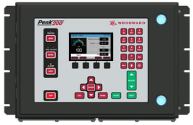
The Peak200 series controllers come in multiple models to meet different operating conditions and installation requirements. From the perspective of installation methods, there are two options: Bulkhead Mount and Front Panel Mount. In terms of voltage adaptation, it covers low voltage (LV, such as 24 VDC) and high voltage (HV, such as 120/220 VAC) models. In addition, there are corresponding certified models for hazardous areas such as ATEX Zone 2, Class1 Div2 Haz. Loc. Compliant, etc., to ensure safe and stable operation in special environments.
Product advantages
High control accuracy: Supports proportional, integral, and derivative (PID) control algorithms, enabling precise control of key parameters such as speed and load. In terms of speed control, the control error can be as low as ± 0.5% to ensure that the steam turbine always operates in the optimal state; In terms of load response, the response time is less than 500ms, which can quickly adapt to changes in load and ensure the stability and reliability of the system.
Easy to operate: It is a configurable controller on site, with a built-in graphical user interface (GUI) that adopts a menu driven screen design. Site engineers do not need to have complex programming skills to easily configure controls for specific application settings. This convenient operation method not only improves configuration efficiency, but also reduces the requirement for professional skills of operators, making equipment installation, debugging, and daily maintenance easier and more feasible.
Strong environmental adaptability: Some models have undergone sulfur resistant conformal coating treatment, giving them excellent corrosion resistance and the ability to operate stably in harsh environments containing corrosive substances such as sulfur. The working temperature range of ordinary position models is -20 ℃ -+60 ℃, while the certified models for hazardous areas strictly follow relevant standards to ensure safe operation in hazardous environments. The product has a wide range of applications and can meet the steam turbine control needs of different industries and environments.
High cost-effectiveness: Its single design can be widely applied to various control application scenarios, and enterprises do not need to purchase multiple complex controllers for different projects or needs, greatly reducing procurement and customization costs. At the same time, the product has a short delivery time, which can quickly meet the urgent needs of the project, reduce the overall project cycle, improve the production efficiency of the enterprise, and bring higher economic benefits to the enterprise.
Good continuity of functional upgrades: Based on the mature 505 platform, a new design has been carried out, inheriting some mature technologies and basic functions of the 505 platform, such as speed control PID, startup mode (manual, automatic), critical speed band, remote speed set point (configurable), overspeed protection and testing capabilities, acceptance of redundant speed sensors, user configurable, etc., ensuring the stability and reliability of the product; On this basis, functional upgrades have been made, adding new features such as graphical HMI, front panel configurability (without the need for handheld devices), multilingual capability, first trip event latch, trip and alarm logs, real-time trends, internal turbine simulator, and one process control PID (cascaded PID), providing users with a richer, more convenient, and efficient user experience.
Model and configuration specifications
Installation method
Bulkhead Mount: Suitable for internal integration of equipment, saving space
Front Panel Mount: convenient for on-site operation and visual monitoring
Voltage level
Low voltage (LV): 24 VDC (typical models: 8200-1500, 8200-1503)
High Voltage (HV): 120 VAC/DC, 220 VAC (Typical Models: 8200-1501, 8200-1504)
Hazardous Area Certification
ATEX Zone 2: Suitable for explosive gas environments (such as 8200-1502, 8200-1505)
Class1 Div2 Haz. Loc. Compliant: North American Hazardous Area Certification (e.g. 8200-1508, 8200-1509)
2301E-ST belongs to the Woodward Industrial Turbine Control series, mainly used for automated control of steam turbines. It can achieve functions such as speed regulation, load distribution, and safety protection of turbines, and is suitable for industrial scenarios such as power generation and mechanical drive.
Model and specifications
2301E-ST: Steam Turbine Controller, Common Position 8273-1013
2301E-ST Hazardous Location Zone 2: Steam Turbine Controller, suitable for Hazardous Zone 2 8273-1014
Key Function
Speed control: Accurately adjust the steam turbine speed to ensure stable operation.
Load sharing: Supports load distribution when multiple turbines are running in parallel.
Security protection: equipped with protection mechanisms such as overspeed and overload, and can be linked with external security systems.
Communication interface: Supports industrial communication protocols (such as CANopen) for easy system integration.
Supporting documents and certification
Product specification document: 03407
User Manual: 26694
Certification: Compliant with industrial safety standards, hazardous area models have passed Zone 2 certification.
Application scenarios
Power industry: speed control and load management of steam turbine generators.
Industrial drive: a steam turbine system that drives machinery such as compressors and pumps.
Accessories and extensions
17 inch touch screen OCP (including RemoteView software): part number 8269-1073, used for human-computer interaction.
Remote View software license: part number 8928-5311, supports remote monitoring.
Comparison of similar products
Compared with the 505 series, the 2301E-ST focuses more on the basic control of industrial steam turbines, while the 505 series (such as 505XT) has more flexible functions and supports more customized programming.
Compared with Peak200: Peak200 is suitable for compact installation, while 2301E-ST is suitable for standard industrial scenarios and has wider compatibility.
Advantage
1. Precise control and efficient performance
High dynamic response speed
By adopting advanced electronic control algorithms, it can quickly respond to changes in the speed of the steam turbine, ensuring stable operation during load fluctuations, with a speed control accuracy of ± 0.1% of the rated speed.
Support real-time adjustment of turbine power output to adapt to dynamic load requirements in scenarios such as power generation and mechanical drive.
Flexible load sharing capability
Built in 2300E electronic load sharing module, which can operate in parallel with multiple turbines or generator sets to achieve automatic load distribution and balancing, improving system efficiency.
2. Safety, reliability, and industrial adaptation
Multiple security protection mechanisms
Integrated overspeed protection logic (can be linked with ProTech series overspeed devices), which quickly triggers shutdown when the speed exceeds the threshold to prevent turbine damage.
Equipped with overcurrent, overheating, and sensor fault diagnosis functions, supporting fault warning and real-time status monitoring.
Wide working condition adaptability
The standard location model (8273-1013) is suitable for standard industrial environments, while the Zone 2 model (8273-1014) for hazardous areas meets the safety requirements for explosive gas environments (such as petroleum and chemical scenes).
Working temperature range -40 ℃~+70 ℃, suitable for harsh industrial environments.
3. Convenient integration and maintenance
Open communication interface
Supports industrial communication protocols such as CANopen and Modbus, and can be seamlessly integrated with DCS (distributed control system) or PLC for system level monitoring and remote control.
Modular design and ease of maintenance
The hardware adopts a modular architecture, and the core components (such as power supply and I/O modules) support hot plugging, reducing downtime for maintenance.
The accompanying RemoteView software (license 8928-5311 required) can monitor the controller status in real-time, download fault logs, and simplify the troubleshooting process.
4. Cost and compatibility advantages
Outstanding cost-effectiveness
Compared to high-end models such as 5009XT, 2301E-ST reduces hardware costs by about 30% while retaining core control functions, making it suitable for small and medium-sized steam turbine systems.
Compatibility and Scalability
It can adapt to various actuators (such as TG series speed controllers, VariStroke hydraulic actuators), support linkage with other Woodward products (such as MicroNet system), and meet the needs of subsequent system upgrades.
2301E-ST steam turbine control: There are two types: normal position and hazardous zone 2, with part numbers 8273-1013 and 8273-1014, respectively. The document refers to product specification 03407 and manual 26694.
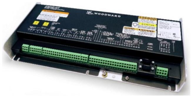
Turbine control: 2301E-HT model is suitable for Francis turbine, 24VDC, normal position, part number 8237-2046, document reference product specification 03459 and manual 35092.
Peak200 steam turbine control: There are multiple installation methods and voltage specifications, such as LV type part number 8200-1500 for cabin wall installation, HV type part number 8200-1501 for front installation, etc. Refer to product specification 03438 and manual 35051 for documentation.
505 steam turbine control: including different voltage and position types, such as LVDC common position part number 8200-1300, HVAC/DC common position part number 8200-1301, etc., as well as 505-XT and 505-DR series. Refer to product specification 03422 and relevant manuals for documentation.
5009XT Steam Turbine Control: Depending on the power supply, there are three types: 2120V AC/DC, 220VAC, and 24VDC, with part numbers 8262-1141, 8262-1142, and 8262-1143. Accessories include a touch screen and software license.
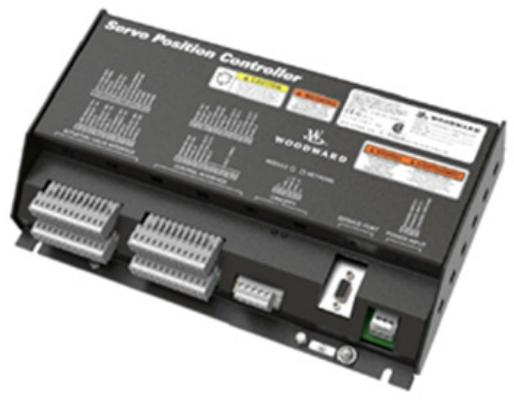
Servo position controller: can replace digital remote final drives, such as the configurable servo/actuator drive part number 8200-226 certified for marine use, and part number 8200-227 with CANOpen communication.
ProTech overspeed protection device: including ProTech SX, ProTech GII, ProTech TPS, MicroNet safety module, etc., with different installation methods and relay configurations, part numbers such as ProTech SX panel installation HV/LV type 8237-1242, ProTech GII cabin wall installation HV/LV independent relay type 8237-2594, and conversion kit.
Compressor control and related equipment
Vertex controllers: available in different voltage and compliance types, such as compressor control part numbers 8200-1370 for 18-36VDC standard compliance, 8200-1371 for 88-264VAC or 90-150VDC standard compliance, etc. Accessories include distributed I/O modules and remote viewing software licenses.
Electronic control
2300E electronic load sharing and speed control: available in hardware only version, with part numbers 8273-1017 for regular location and 8273-1018 for hazardous area 2. Refer to product specification 03405 and manual 26691 for documentation.
Flex500 platform: There are different installation methods and voltage types, such as front mounted LVDC with OCP part number 8200-1343, back mounted HVAC/DC part number 8200-1354, etc. Accessories include core source license and communication module.
MicroNet system modules, cables, and accessories:
Chassis: such as 8-slot MicroNet Plus chassis part number 5453-829, TMR chassis part number 5453-279.
Power supply: including MicroNet Plus power supply with 24VDC, 110VAC/125VDC, 220VAC input, and TMR power supply.
CPU modules: such as 5200CPU MicroNet TMR part numbers 5466-1347 and 5466-1247, MicroNet Plus P1020 CPU part number 5466-1511.
Communication module: such as RTN to CAN gateway part number 8200-1250, remote RTN part number 5466-1146.
Input/output module: including speed sensor, pressure interface, actuator driver, etc., such as 4-channel speed sensor part number 5466-5000, 2-channel actuator driver part number 5501-1428.
LINKnet HT and RTCnet modules: For example, RTD inputs 8-channel part numbers 8200-1200 and 8200-1100, and thermocouple inputs 8-channel part numbers 8200-1201 and 8200-1101.
Dataforth I/O: including K-type thermocouple, 100 Ω RTD, 4-20mA input, and 0-5VDC input module, part numbers such as 1784-1028, 1784-655, etc.
Network switch: 8-port Ethernet switch part number 1711-1350.
Cables: including NetCon analog and discrete cables, Ethernet Cat-5 cables, MicroNet TMR cables, etc., such as 6-foot NetCon analog cable part number 5416-346, 3-foot NetCon discrete cable part number 5416-332.
MicroNet TMR and Plus hardware kits: such as TMR hardware kits with 4565-1115 part numbers 8262-1145 to 8262-1150, standard MicroNet+kit part numbers 8262-3183, etc.
Magnetic pickups and active proximity probes: Magnetic pickups have different threads, lengths, and resistances, such as MPU-70 VPP part number 202816, MPU-50 VPP part number 1680-613; Active proximity probes such as 5-24VDC part number 1680-986 and 7-30VDC part number 1689-1114.
Software License
GAP software program: GAP-Reader does not require a license, Monitor GAP license part number 8928-5007, Editor GAP 4. X license part number 8928-5359.
The latest ITCC software core includes ASC1 to ASC4 anti surge control, STC steam turbine core, etc., with part numbers such as 5418-3675 to 5418-3678, 10-027-206, etc.
GUI development and viewing program licenses: CIS annual subscription license part number 1796-3131, RemoteView license part number 8928-5311, iFix HMI software licenses such as 1796-3132 and 1796-3145.
Software service tool programs and suites: Control Assistant license part number 8928-5014, ToolKit developer license part number 8928-5016, AppManager data log retrieval enterprise license part number 8928-5009.
NetSim simulation license: NetSim nVe Nodes Only license part number 8928-5363, Advanced license part number 8928-5364, and annual subscription license.
Remote access program: Site Manager Module part number 1711-1418, LinkManager license part number 8928-5347, GateManager setup and support fees.
Electro hydraulic governor and actuator
TG turbine governor: such as TG13 and TG17 series, with different speeds, rotation directions, and droop rates, part numbers such as TG13 screw 2400rpm CCW rotation ATEX part number 9904-814, TG17 screw 2400rpm CCW rotation ATEX part number 9904-800.
TG611: Includes conversion kit and different specifications of speed controllers, such as TG611-13 screw 2400rpm CCW with OTD part number 8516-175.
TGE turbine actuator: There are 2400rpm, 4000rpm, 6000rpm according to different speeds, with part numbers such as TGE13 2400rpm part number 9904-110.
VariStroke actuator: It needs to be selected according to the model number, with double acting and single acting options. The part number is V45TD-2015-FUXM-X-S-X, part number 9907-1338, as well as VS-I, GI, DX servo and spare parts kit.
UG25+steam turbine governor and actuator: governor part numbers such as 8528-122 to 8528-137, actuator part numbers such as 8528-027 to 8528-327.
UG actuators: such as UG2 MPU CW dual lip drive seal part number 8251-212, UG15 series part number 8251-719, etc.
CPC-II current pressure converter: available in different pressure and area levels, such as 10Bar Class1 Div2 part number 9907-1200, 25Bar Class1 Div1 part number 9907-1197, and CPC-DX redundant kit.
TM linear actuator: such as TM-25LP single coil extension part number 9907-1213, TM-200LP single coil retraction part number 9907-1225.
Turbine shutdown trip block components: The QuickTrip series is SIL-3 certified, with part numbers 0-9907-2108 for regular positions and 1-9907-2108 for Zone 1&2 positions. Spare parts include specialized tool kits and solenoid valve replacement kits.
Gas turbine valve
GS40 and GS50 gas fuel valve actuators: with onboard drivers, GS40 comes in 1.5-inch RF600 # and SAE specifications, part numbers such as 9908-1608 to 9908-1654; GS50 comes in 2-inch RF600 # and SAE specifications, with part numbers such as 9908-1605 to 9908-1673.
LQ6 liquid fuel valve actuator: The part numbers are 9908-1519, 9908-1520, and 9908-271 depending on the port size.
LQ25 standard valve: such as 0.1 square inch with PIV and SOV part number 9908-238, 0.2 square inch part number 9907-696, 0.3 square inch part number 9907-996.
LSOV25 liquid fuel shut-off valve: available in 24VDC and 125VDC, with proximity switch, part numbers such as 9908-359, 9908-358, 9908-363, 9908-361.
USOV universal shut-off valve: 2-inch 900 #, 1.6ACD, 24VDC part number 9907-1233.
GSOV80 and GSOV25HT gas fuel shut-off valves: GSOV80 is 3-inch HP, 24VDC and 125VDC, part numbers 9907-2328, 9907-2335; GSOV25HT has 24VDC and 125VDC, with on/off position switch, part numbers such as 9907-861 to 9907-899.
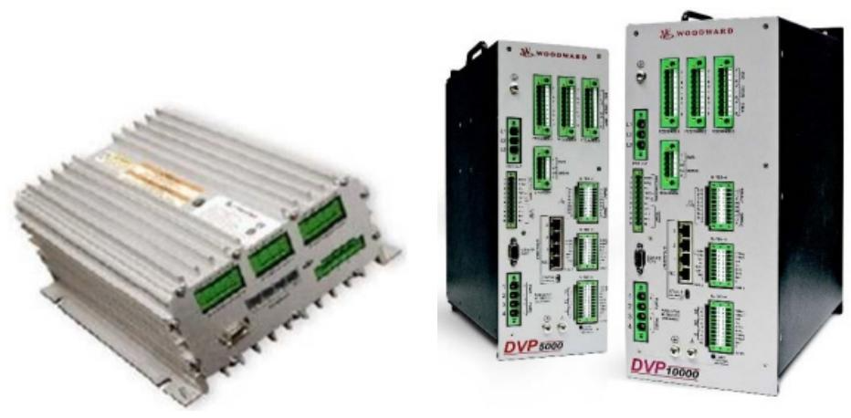
DVP digital valve positioner: available in 24VDC and 125VDC, with different protection levels and output powers, such as 24VDC IP30 TB input/output part number 8200-507, high output 5KW part number 8200-538, 10KW part number 8200-536, 12KW part number 8200-556.
L series actuators and integrated speed control
L series speed control – actuator only: part number 8404-7101, similar to 8404-536 and 8404-1001.
L series speed control – with ITB actuator: Depending on the ITB size, such as 36mm part numbers 8404-2007 and 8404-7, 43mm part numbers 8404-2008 and 8404-7, 50mm part numbers 8404-2009 and 8404-2033.
L series process control – with ITB: including air-fuel ratio control, such as 16mm trim valve part numbers 8404-3001 and 8404-7301, 22mm part numbers 8404-3002 and 8404-7302, and sealed ITB such as 25mm part numbers 8404-2035 and 8404-2061.
L series speed control – with ITB and Venturi mixer (MAS): such as LC50 25mm ITB part number 8404-4001, 30mm ITB part numbers 8404-4002 to 8404-4009 and 8404-7405 to 8404-7409.
L series diesel actuator applications: such as Stanadyne cover/shaft speed control part numbers 8404-563 and 8404-7503, Delphi cover/shaft with lever part numbers 8404-5004 and 8404-7504.
L series with ITB locator: such as 16mm fine adjustment valve part numbers 8404-3003 and 8404-7303, 22mm part numbers 8404-3004 and 8404-7304, sealed ITB such as 25mm part numbers 8404-2013 and 8404-7213.
L series accessories: including gaskets, HEGO sensors, cables, and communication interface kits, such as 16&22mm gasket part number 3051-073, HEGO sensor part number 1680-6005.
F-series actuators and actuators with ITB
F-series locator: There are different ITB sizes and installation methods, such as 33mm ITB standard installation 23 pin part number 8245-027, 48mm ITB standard installation 23 pin part number 8245-052, 60mm ITB standard installation 23 pin part number 8245-003, 68mm ITB standard installation 23 pin part number 8245-004. Accessories include 14 pin and 23 pin mating connector kits.
R series actuators
R-series actuators: R-11, R-30, R-120 electric positioners, R-11 is suitable for fuel racks, part number R11 positioners are not preferred 8410-001, replace 8410-007; R30 locator replacement 8410-008; R120 locator 8410-010.
ProAct actuator
ProAct 75 Speed Control (First Generation): Old part number such as 8400-010, new part number 8400-059, including driver and ITB, such as driver part number 8400-706, ITB part number 8235-399.
ProAct locator (16 pin, third-generation): Model II part number 8404-302, Model III part number 8404-303, Model IV part number 8404-304.
ProAct locator (Flex I/O): such as GEN3 FLEX Model II part numbers 8404-307, 8404-317, 8404-319, Model III part numbers 8404-308, 8404-318, Model IV part numbers 8404-309, 8404-315, etc.
ProAct ITB (3rd generation): 105mm ITB part number 8335-003120mm ITB part number 8335-004135mm ITB part number 8335-005.
TecJet fuel control valve
TecJet fuel control valve: suitable for different systems, such as TecJet 52 part number 8407-605 for EGS-01, part number 8407-603 for EGS-02/E6, Jenbacher specific part number 8407-636, CAT specific part number 525-8021, as well as TecJet 85 and 110 series.