Call us 24/7uaedcs@163.com
Welcome to the official website of CNIACS Automation Technology Co., Ltd!
Call us 24/7uaedcs@163.com

SIEMENS 3AH3 vacuum circuit breaker

Product Overview and Core Features

Basic positioning: Siemens 3AH3 vacuum circuit breaker belongs to medium voltage equipment, with document version 2018 (HG 11.03), replacing the old version 2010. The product production and sales follow ISO 9001, ISO 14001, BS OHSAS 18001 certification management system.

Core advantages:

Maintenance free design: Under normal conditions (compliant with IEC 62271-1), there is no need for re lubrication or adjustment throughout the entire service life, and the characteristics are not affected by switching frequency or idle time. It supports up to 10000 operating cycles.

Wide voltage coverage: Suitable for the conventional medium voltage range of 7.2kV-40.5kV, meeting the needs of industrial and generator scenarios.

High load capacity: The maximum rated normal current of conventional models is 6300A, and the maximum short-circuit breaking current is 72kA; under the “phase separation” design scheme, the maximum rated normal current is 12000A, and the maximum short-circuit breaking current is 90kA.

Product Classification and Applicable Standards

1. Product classification and scenarios

Product type follows standard core applicable scenarios and key enhanced features

Conventional high-voltage circuit breakers IEC 62271-100 are used in industrial scenarios (such as oil refineries) to control small inductive/capacitive load currents to high-voltage short-circuit currents-

Generator circuit breaker (3AH3 6/7/8 series) IEC 62271-100+IEC/IEEE 62271-37-013 Generator operation, switching between generator power supply failure and system power supply failure 1. Coping with generator power supply failure: high DC component, no current zero point; 2. Coping with system power supply failures: higher TRV rise rate; 3. Higher testing voltage level

Split phase design circuit breaker IEC 62271-100+IEC/IEEE 62271-37-013 for large generator switchgear, single-phase isolating switch (independent enclosure) 1. Optimize parallel operation; 2. The maximum short-circuit breaking current is 90kA; 3. The maximum rated normal current is 12000A

2. General standard compliance

Basic standards: IEC 62271-100 (for circuit breakers), IEC 62271-1 (for medium voltage equipment) VDE 0671

Endurance level: All 3AH3 vacuum circuit breakers meet the E2, M2, C2, and S1 levels (IEC 62271-100)

Structure and Working Principle

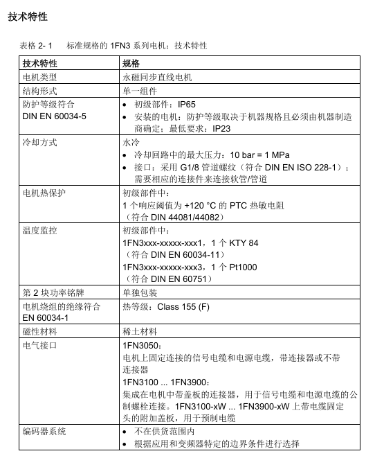
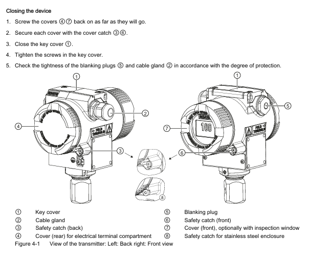
1. Core structure (including component functions)

Core functions of structural components

Pole component (1) vacuum arc extinguishing chamber (6), upper/lower arc extinguishing chamber bracket (5/7), post insulator (3) 1. Vacuum arc extinguishing chamber: based on more than 40 years of mature vacuum switch technology, arc extinguishing is achieved; 2. Air insulation design, easy to clean insulation components; 3. Bear the external force and contact pressure of switch operation

Operating mechanism box (2) includes energy storage mechanism, release device, auxiliary switch, indicator, and actuator 1. It accommodates all operating mechanisms; 2. The configuration of secondary devices can be adjusted according to application scenarios to meet diverse needs

Transmission component operating rod (4), lever transmission switch action, connecting operating mechanism and pole assembly

2. Key operational mechanisms

Energy storage mechanism: The closing spring is an energy storage component that can store energy electrically or manually, and is locked after the energy storage is completed; When closing, unlock through the local “ON” button (mechanical) or remote control (electric). During the closing process, charge the opening/contact pressure spring, and automatically re store energy after discharge. It supports the OPEN-CLOSE-OPEN operation sequence.

Free release mechanism: in accordance with IEC 62271-100, if a closing command is issued and an opening command is received, the moving contact returns to the opening position and maintains it, avoiding continuous closing opening “pumping”.

Closing method:

Standard configuration: Remote electric closing, local mechanical unlocking closing spring (manual mechanical closing)

Optional configuration: Manual electric closing (electrically controlled closing circuit through button, compatible with switch equipment interlocking)

3. Types and functions of release devices

Release type, power supply method, core function

Closing the soleoid DC/AC unlocks the stored energy closing spring to achieve electrical closing

External power supply (DC/AC) for shunt release, connected to voltage transformer in special circumstances. 1. Automatic disconnection through protective relay; 2. Electrical manual disconnection

When the CT operated release has no external auxiliary power supply (such as no battery), it is triggered by a protective relay (such as overcurrent time protection). When the tripping current exceeds 90% of the rated normal current, the energy storage mechanism is unlocked and the circuit is opened

When the undervoltage release circuit breaker is closed, it is permanently connected to the secondary/auxiliary voltage. When the voltage is lower than the preset value, it is unlocked and opened through the energy storage mechanism; 2. Can be connected to a voltage transformer, which automatically opens when the voltage is too low; 3. Can be paired with energy storage components to achieve delayed disconnection\

Environmental conditions and technical parameters

1. Environmental conditions (compliant with IEC 60721-3-3)

Key limitations of environmental category level

The lower limit of low temperature in the 3K4 climate environment is -5 ℃, with no icing or wind blown precipitation

Biological Environment 3B1-

Mechanical environment 3M2-

Chemical active substance 3C2-

Mechanical active substance 3S2 requires cleaning of insulation components

2. Current carrying capacity and insulation strength

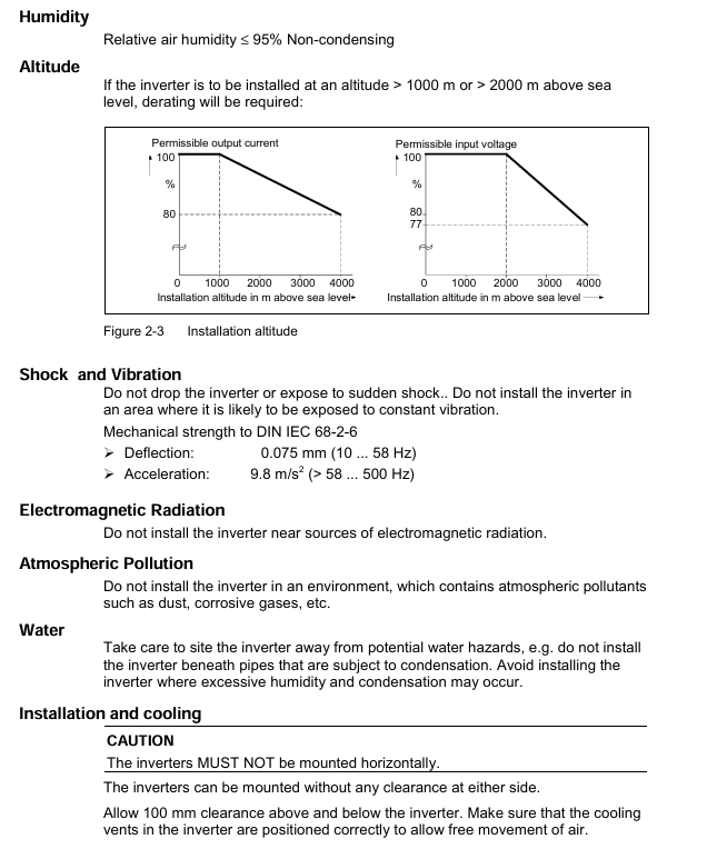
Current carrying capacity: The rated normal current is based on an ambient air temperature of 40 ℃ (open type switchgear), and can be increased when the temperature is below 40 ℃. The rated current levels include 1250A, 2000A, 2500A, 3150A, 4000A, 5000A, and 6300A (corresponding to characteristic curves 1-7).

Insulation strength:

Reference conditions: At an altitude of 1000m (above sea level), the rated lightning impulse withstand voltage and rated short-time power frequency withstand voltage are taken according to the “Technical Data” section.

High altitude correction: When the altitude is greater than 1000m, it needs to be adjusted according to the formula U ≥ U 0 × K a (U is the reference environmental withstand voltage, U 0 is the required withstand voltage of the installation site, K a is the altitude correction factor, which increases with altitude).

Example: When a lightning impulse withstand voltage of 75kV is required at an altitude of 2500m, the reference environment must be at least 90kV (90kV ≥ 75kV × 1.2).

3. Capacitor switch capability (endurance class C2, IEC 62271-100) Rated voltage U r (kV) Rated line charging breaking current I I (A, r.m.s.) Rated cable charging breaking current I c (A, r.m.s.) Rated single capacitor group breaking current I sb (A, r.m.s.) Rated back-to-back capacitor group breaking current I bb (A, r.m.s.) Inrush current frequency f bl (Hz)

7.2 10 10 400 400 4250

12 10 25 400 400 4250

17.5 10 31.5 400 400 4250

24 10 31.5 400 400 4250

36 10 50 400 400 4250

40.5 10 50 400 400 4250

Note: The capacity of the circuit breaker capacitor switch is 0.7 × I r of the standard specification

Selection and Configuration Guide

1. Order number structure (16 digits)

Explanation of Position Meaning

1-3 superior group/main group/sub group 1: switchgear; 2: Circuit breaker; 3 digits: Circuit breaker series

The 4-8 bit main device includes design and main device parameters (voltage, current, pole spacing, etc.)

9-16 position secondary equipment operating mechanism, release, operating voltage, auxiliary equipment, etc

Order code supplementary configuration 9/Equipment version marked with “Z” digit, supplemented with 3-digit code (a n a format), can be continuously added multiple times

Add “- Z” to the order number for special version customization requirements, followed by descriptive code; Y99 is used for unspecified special requirements and needs to be negotiated with Siemens

2. Selection of main equipment (by voltage level)

Taking some key voltage levels as examples, demonstrate the adaptation relationship between rated short-circuit breaking current and rated normal current (excerpt):

Rated voltage (kV) Rated short-circuit breaking current (kA) Rated normal current (A) – Pole distance (mm) Adaptation

7.2 50 1250(210)、2500(210/275)、4000(275/350)

7.2 63 2000(275)、3150(275)、4000(275/350)

12 50 1250(210)、2500(210/275)、4000(275/350)

12 63 2000(275)、3150(275)、4000(275/350)

36 31.5 1250(350)、2500(350)、4000(350)

36 40 3150(350)、4000(350)

Note: “n” indicates that the combination is optional

3. Selection of secondary equipment (core configuration)

Description of optional scope of configuration items

Operating mechanism electric (excluding hand crank), manual (including hand crank) Hand crank can be ordered separately as accessories

Closing method: Solenoid+manual mechanical closing, manual electric closing. Manual electric closing can be adapted to switch equipment interlocking to prevent accidental closing

Up to 3 release combinations can be used (based on 1 shunt release, additional shunt/CT operation/undervoltage release can be added). Please refer to page 19 of the document for specific combinations

Auxiliary switches 6NO+6NC, 12NO+12NC-

Plug/Terminal: 24 pole terminal block, 24 pole plug, 64 pole plug. The interface of the 64 pole plug can be connected to idle auxiliary contacts by the user

Interlock free, mechanical interlock, mechanical interlock adapted to circuit breaker handcart, withdrawal component or isolation switch

4. Additional equipment (some key options)

Additional equipment function order code

Anti condensation heating 230V AC, 50W, anti condensation Z A30

Silicon free design suitable for special environmental requirements Z A31

Low temperature adaptation (-25 ℃) can operate Z A40 in an environment of -25 ℃

3AH37 horizontal installation (≥ 5000A) 3AH37 model 5000A and above horizontal installation supplement Z A70

Gold plated auxiliary switch enhances contact reliability and adapts to different interfaces Z A17/Z A18/Z A20/Z A21

Routine test certificate with seal and report/report only/with seal signature Z F19/Z F20/Z F21

Accessories and after-sales support

1. Main accessories and spare parts (excerpt)

Attachment/Spare Part Name Specification/Remarks Order Number

Hand crank short/standard/long 3AX15 30-4A/4B/4C

Lubricant 180g Kl ü ber Isoflex Topas L32N 3AX11 33-3H

Cable bundle for 64 pole plug/24 pole plug/24 pole terminal block 3AX11 34-2D/2B/2C

Vacuum arc extinguishing chamber compatible with 3AH3117-7 model 3AY17 15-2J

Vacuum arc extinguishing chamber compatible with 3AH3228-8 model 3AY17 15-4J

Closing soleoid 24V DC 3AY15 10-5K

Undervoltage release 24V DC 3AX11 03-2B

2. Key requirements for after-sales service

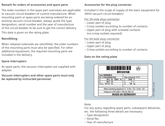
Ordering spare parts: Equipment model, serial number, and manufacturing year (all on the nameplate) must be provided to ensure compatibility.

Modification requirements: When modifying the release/solenoid, the installation component order number must also be specified; Other additional equipment includes necessary installation components.

Professional operation: The vacuum arc extinguishing chamber and some spare parts need to be replaced by trained personnel.

SIEMENS QFM31xx series air duct sensor

Product basic information

1. Product model

Covering sub models such as QFM3100 (basic version), QFM3160 (with display), QFM3171D (4-20mA output), etc., collectively referred to as the QFM31xx series, it provides high-precision measurement of air duct temperature and humidity.

2. Application scenarios

Sensors are suitable for ventilation and air conditioning systems with high requirements for temperature and humidity accuracy and response speed. Typical installation scenarios include:

Industrial scenarios: storage and production workshops in paper mills, textile factories, pharmaceutical factories, food factories, and electronic factories;

Special venues: laboratories, hospitals, computer data centers, indoor swimming pools, greenhouses;

Functional roles: Air supply/return control sensor, humidity limit sensor after steam humidifier, building automation system (BAS) access sensor.

Core technical characteristics of the product

1. Power supply and signal output

Category parameter content, key data

Supply voltage AC/DC dual compatible 24 Vac (± 20%, 50/60Hz); 13.5-35 Vdc

Low power consumption design<1 VA

Humidity output with two signal types: 0-10 Vdc (corresponding to 0-100% RH, maximum current 1mA); 4-20 mA (corresponding to 0-100% RH)

The temperature output range can be selected from 0-10 Vdc/4-20 mA, and the range can be selected through jumper wires (see Table 2)

Cable lengths are classified by wire diameter as 24 AWG (50m), 18 AWG (150m), and 16 AWG (300m)

2. Measurement performance (accuracy and response)

Measurement Type Accuracy Index Response Characteristics Remarks

± 2% RH at relative humidity of 23 ℃; temperature coefficient<0.05% RH/℃ Time constant of about 20s (in flowing air) Effective measurement range 0-95% RH (0-9.5V/4-19.2mA linear)

± 0.8 ℃ at a temperature of 15-35 ℃; -The time constant of ± 1.0 ℃ at 40-15 ℃/35-70 ℃ is about 20 seconds (in flowing air). The sensing element is NTC 10K Ω

3. Protection and environmental adaptability

Protection level: IP65 (NEMA 4), dustproof and water-resistant, suitable for humid air duct environments;

Work environment: Adapt to the air temperature inside the duct (consistent with the selected temperature range), humidity 0-100% RH;

Material compatibility: The shell is made of polycarbonate (impact resistant), the filter cap is made of the same material, and the overall silicon free design avoids polluting sensitive environments (such as electronic factories).

Mechanical Design and Installation Specification

1. Mechanical structure

Overall composition: consisting of a housing (base+detachable cover plate), a printed circuit board (PCB), wiring terminals, mounting flanges, and an immersion probe (including sensing elements and filter caps);

Shell design:

Base: Integrated wiring terminal and conduit clamping system (fixing flexible conduit), color RAL 7001 (silver gray);

Cover plate: Built in measurement circuit and jumper (range configuration), color RAL 7035 (light gray), fixed with screws;

Probe: Made of polycarbonate material (RAL 7001), the end sensing element is protected by a filter cap to prevent dust contamination.

2. Installation method and requirements

Key requirements for installation method and operation steps

Install flange (recommended) 1. Assemble the flange with the sensor; 2. Fix the flange to the air duct according to the required immersion length; 3. Insert the sensor and tighten it to adjust the immersion length as needed. The flange material is PA66 (black)

No installation flange 1. Use 4 mounting holes on the shell; 2. Directly screw the sensor onto the air duct using the maximum immersion length to ensure measurement representativeness

Special scenario (dew point offset) 1. Only fix the flange to the air duct wall; 2. Insert the sensor from the flange and clamp it tightly. It must be installed in the return air duct to avoid measurement deviation

Installation taboos:

Avoid probe impact: Sensing components are easily damaged by impact and should be handled gently during installation;

Distance between steam humidifiers: The minimum distance from the humidifier should be ≥ 3m (recommended ≤ 10m) to prevent sudden humidity changes from affecting accuracy;

Sealing protection: It is forbidden to remove the seal between the shell and the cover plate to prevent water vapor from entering and damaging the circuit.

Parameter configuration and debugging

1. Jumper configuration (on PCB, under cover)

The jumper has 6 pins and 1 jumper cap, which is used to select temperature range, display unit, and activate testing functions. The specific configuration is as follows:

Configure the parameters corresponding to the jumper position of the configuration function

Temperature range selection left (1) -31 ° F~95 ° F (-35 ℃~35 ℃)

Right position (3) -40 ° F~158 ° F (-40 ℃~70 ℃)

Display unit selection (with LCD model) vertical right position Celsius (℃, factory default)

Vertical left Fahrenheit (℉)

Test function activation level signal output specific values (such as 0V/10V, 4mA/20mA) for troubleshooting

2. Debugging steps

Wiring inspection: Confirm that the power and signal lines are connected correctly (refer to the terminal definition in Figure 2-6, for example, QFM3171 needs to ensure that G1/I1 is powered on, even if only temperature output is used);

Range configuration: According to on-site requirements, set the temperature range and display unit through jumper wires;

Power on verification: Connect the power supply and check if the output signal (humidity 0-10V/4-20mA, temperature corresponding range signal) is normal. For models with LCD, it is necessary to confirm the alternating display of temperature and humidity (5-second interval).

Fault diagnosis and spare parts

1. Fault diagnosis (output characteristics when sensor failure occurs)

Fault type: Humidity signal output (U1/I1) Temperature signal output (U2/I2) Remarks

Temperature sensor fault rises to 10V (0-10V output) or corresponding 20mA (4-20mA output) drops to 0V (0-10V output) or corresponding 4mA (4-20mA output). The fault is immediately triggered

The humidity sensor malfunctions for 60 seconds and then rises to 10V/20mA to maintain normal output with a delay of 60 seconds, making it easier for the system to identify

2. Spare parts list (for replacement)

Spare part model, spare part name, and purpose

The AQF3101 filter cap protects the sensing elements inside the probe, preventing dust from entering

Replace damaged temperature and humidity sensing components with AQF3150 sensing head

74 662 01040 1/2 inch rigid conduit adapter for connecting conduit to sensor base

Compliance and physical specifications

1. Certification and Standards

Compliance Directive: Complies with EMC Directive 2004/108/EC (Electromagnetic Compatibility) and AS/NZS 3548 (Radio Interference Emission Framework Standard);

Electrical specifications: The power supply requires the use of a Class II transformer (independent winding, 100% duty cycle), and the selection should consider sensor power consumption and local electrical regulations.

2. Physical specifications

Project specification parameters

Material base/probe: polycarbonate (RAL 7001); Cover plate: polycarbonate (RAL 7035); Flange: PA66 (black)

Protection level IP65 (NEMA 4)

Weight (including packaging) without LCD display: 7.34 ounces (0.208kg); With LCD display: 23.49 ounces (0.666kg)

The wiring terminal is compatible with 14 AWG (1 way) or 16 AWG (2 ways) wires

Engineering precautions

Power selection: Class II transformers must be used with independent winding design to ensure safe isolation;

Cable selection: Shielded twisted pair cables are required for EMC interference environments, and secondary power lines and signal lines need to be twisted to reduce interference;

Wiring specifications: Avoid long-distance parallel laying of cables (too small spacing can easily cause interference), strictly follow the allowed cable length (distinguished by wire diameter);

Maintenance requirements: Regularly check the cleanliness of the filter cap (contamination can affect response speed), and replace it promptly if it is damaged.

SIEMENS SIMOTICS SD 1LE7 series low-voltage motor

Product positioning: Three phase asynchronous induction motor, with a shaft height coverage of 71-315mm, available in self ventilated (IC411) and forced ventilated (IC416) versions, suitable for industrial drive scenarios, supporting direct grid operation (50/60Hz) and variable frequency drive (such as SINAMICS G/S series).

Typical applications: Industrial equipment such as fans, pumps, compressors, and conveyors, suitable for continuous and intermittent operation.

Safety warning system (core emphasis)

1. Risk grading standards

Adopting a four level risk warning system to clarify the level of risk and response requirements, with a focus on electric shock and injuries to rotating parts

Warning level identification, risk description, typical scenarios

DANGER red safety symbol. Failure to protect may result in death/serious injury. Contact with live parts and rotor falling (when installed vertically)

Warning: The red safety symbol does not provide protection and may cause death/serious injury. Contact with rotating parts and burns on high-temperature surfaces

CAUTION yellow safety symbol may cause minor injury if not protected. Foreign objects may splash during compressed air cleaning

NOTICE unsigned and unprotected may cause property damage, cable shielding errors, and loose bolts

2. Special hazard prevention and control

Electric shock hazard:

Risk: When live parts are exposed, the contact voltage can be fatal, and there may still be residual voltage of ≥ 60V at the terminals after power failure;

Prevention and control: Strictly follow the “5 safety rules” (power-off → anti misoperation → electricity inspection → grounding → protection of adjacent live parts), and match the PE wire cross-section with the phase wire (PE=S when S ≤ 25mm ², PE=0.5S when S>50mm ²).

Danger of rotating parts:

Risk: unprotected rotating components such as fans and couplings can easily cause entanglement injuries;

Prevention and control: It is necessary to install a protective cover. After stopping the machine, wait for the rotor to come to a complete stop (≥ 5 minutes) before removing the protective cover.

High temperature hazard:

Risk: The temperature of the winding/bearing during motor operation may exceed 100 ℃, and the temperature may further increase during anti condensation heating operation;

Prevention and control: Stick a “hot surface” label, cool for at least 30 minutes before maintenance, and interlock the anti condensation heating with the main motor (heating is turned off when the motor is running).

Product Core Features

1. Structure and composition

Component Function Description Key Parameters/Requirements

The stator contains three-phase windings and provides magnetic field insulation level Class 155 (F level). The winding temperature monitoring can be selected from PTC/KTY84/Pt1000

The rotor induced current generates torque dynamic balance level A (optional level B), and the balance methods are divided into “H” (half key), “F” (full key), and “N” (no key)

Bearing supports the rotor, transmits radial/axial force through rolling bearings, with a shaft height of ≤ 200 for permanent lubrication, ≥ 225 with M10 oil injection nozzle, and a design life of ≥ 50000 hours (horizontal coupling)

Cooling system export loss heat self ventilation IC411 (standard, fan installed at the shaft end), forced ventilation IC416 (optional, independently driven fan)

The electrical connection interface of the terminal box can rotate 4 × 90 °, with a protection level of IP65, and the cable entry is compatible with M16-M63 cable glass

2. Key technical parameters

Environmental adaptability:

Operating temperature: -20~+50 ℃ (beyond which capacity reduction is required);

Installation altitude: ≤ 1000m (power reduction of 10% for every 1000m above sea level);

Humidity: ≤ 60% (no condensation), condensation environment requires optional anti condensation heating (power ≤ 50W).

Electrical performance:

Voltage range: Complies with IEC 60034-1 Zone A (voltage fluctuation ± 5%, frequency fluctuation ± 2%);

Insulation resistance: New motor ≥ 100M Ω, during operation ≥ 30M Ω (500V DC test);

Bearing current protection: Insulated bearings (NDE end) can be selected when driving the frequency converter, and EMC grounding (shielded cable double end grounding) is required.

Vibration and noise:

Vibration level: Standard A (compliant with ISO 10816-3), optional B level;

Noise emissions: ≤ 70dB (A) (at rated power), textile industry specific motors require regular cleaning of fan cover fluff.

Full lifecycle operating standards

1. Transportation and Storage

Transportation requirements:

Packaging: Wooden packaging complies with ISPM 15 and is labeled with “Fragile”, “Moisture proof”, and “This Side Up” signs;

Lifting: Use the motor’s built-in lifting ring (with M16 lifting ring for shaft height ≥ 180), with a 2-point lifting angle ≤ 45 °. Single motor lifting of the unit is prohibited.

Storage requirements:

Environment: Indoor dry, dust-free, vibration free, temperature -20~+50 ℃, humidity ≤ 60%;

Protection: Apply rust inhibitor (such as Tectyl) to the shaft end/flange surface. For long-term storage (>12 months), rotate the rotor monthly (to avoid bearing indentation), drain the cooling system, and lock the interface;

Rotor fixing: During transportation, rotor fixing components need to be installed, and vertically installed motors need to be stored in a vertical position.

2. Mechanical installation

General rules:

Bolt: Only use new bolts of grade 8.8 or above, with no oil/paint on the fixing surface and a surface roughness of Rz 10-40 μ m;

Tightening torque: M5=5Nm, M6=8Nm, M8=20Nm, M10=40Nm, optional Loctite 243 anti loosening.

Installation in different scenarios:

Horizontal foot installation (IM B3): Adjust the levelness with shims, with a support surface flatness of ≤ 0.2mm (shaft height ≥ 180);

Flange installation (IM B5): The flange centering surface is coated with paste, and the bolts are pre tightened in a 120 ° distribution, and finally tightened in diagonal order;

Vertical installation (IM V1): The rotor needs to be supported (to avoid bearing overload), and a protective cover should be added when the shaft end is facing downwards (to prevent foreign objects from falling in).

Alignment requirements:

Speed (rpm) Parallel deviation (mm) Angular deviation (mm/100mm Coupling diameter)

750 0.09 0.09

1500 0.06 0.05

3000 0.03 0.025

3. Electrical connection

Safety requirements:

Power supply: Only connect to the matching frequency converter or power grid, and do not directly connect to the three-phase AC power grid (frequency converter drives the motor);

Grounding: The PE wire is directly connected to the power module, and the grounding terminal inside the terminal box needs to be fastened with M5 bolts (torque 1.8-2.5Nm).

Specific connection:

Power cable: 4-core (PE=green yellow, U=black, V=black, W=black), core wire cross-section selected according to rated current (2.5mm ² corresponds to 21A, 16mm ² corresponds to 66A);

Control cable: The temperature sensor/anti condensation heating cable needs to be wired separately from the power cable, and the shielding layer should be grounded at one end;

Terminal marking: According to EN/IEC 60034-8, U/V/W corresponds to L1/L2/L3, and swapping any two phases can change the direction of rotation.

4. Debugging

Debugging premise:

Mechanical: Complete installation alignment, manually rotate the rotor without any obstruction;

Electrical: Insulation resistance ≥ 30M Ω, reliable PE grounding, cable gland tightened (M20 gland torque 12Nm).

Key steps:

No load test run: Power on and run for 5 minutes, check the steering (clockwise is U-V-W phase sequence) and vibration (≤ 4.5mm/s);

Load trial operation: gradually load to rated load, monitor current (≤ rated current), bearing temperature (≤ 115 ℃ alarm, ≤ 120 ℃ shutdown);

Variable frequency drive debugging: Parameterize the variable frequency drive (input motor rated current, speed, number of poles), set the avoidance frequency (38-48Hz, shaft height 315 two pole motor).

5. Operation and maintenance

Operation monitoring:

Normal parameters: current ≤ rated value, bearing temperature ≤ 90 ℃, vibration ≤ 4.5mm/s;

Troubleshooting: Motor cannot start (check for overload/phase loss), overheating (check for cooling/load), abnormal noise (check for bearings/alignment), please refer to the fault table for details.

Maintenance cycle:

Maintain project cycle content

Initial inspection: 500 operating hours/6 months. Check bolt tightness, bearing temperature, and insulation resistance

Regularly inspect 16000 operating hours/2 years, clean the cooling air duct, grease (with oil nozzle bearings), and check the grounding

Bearing replacement: 50000 operating hours (horizontal)/20000 hours (vertical). Replace bearings and shaft seals, clean the bearing chamber

Insulation testing measures insulation resistance (≥ 30M Ω) and polarization index (≥ 2) every year/after shutdown for more than 3 months

6. Scrapping and disposal

Scrap steps:

Power off → wait for capacitor discharge → cool down for 30 minutes;

Dismantle the cable and drain the coolant (compliant treatment);

Remove the fixing bolts of the motor and disassemble it in reverse order (first remove the fan cover, then remove the end cover).

Waste disposal:

Metal components: classified recycling of steel, aluminum, and copper (winding copper can be melted and recycled);

Insulation material: incineration (in compliance with environmental requirements);

Hazardous substance: Lead (CAS 7439-92-1, content ≤ 0.1%) must be disposed of in accordance with the REACH directive, and packaging materials (PE/PP) are recyclable.

Appendix and Compliance

1. Key Appendix Resources

Spare parts list: including end caps (1.40), bearings (1.60), cable glass (5.03), fans (7.04) and other spare parts models and explosion diagrams;

Tightening torque table: specify the tightening torque for different thread specifications (such as M12 bolt 70Nm, M16 cable glass 170Nm);

Terminal box dimensions: Axis height 71-90 Terminal box TB7 D04 (dimensions A=89mm, B=111mm), Axis height 250-280 Terminal box TB1 NO1 (dimensions A=233mm, B=319mm).

2. Compliance standards

Following standards: EN/IEC 60034 (Rotating Electrical Machinery), EN/IEC 60204-1 (Mechanical and Electrical Equipment), EMC 2014/30/EU (Electromagnetic Compatibility);

Environmental directives: RoHS (Restriction of Hazardous Substances), REACH (Control of Substances of Very High Concern, such as Lead Content ≤ 0.1%)

SIEMENS SIMOTICS L-1FN3 series linear motor

The Chinese operating instructions for the Siemens SIMOTICS L-1FN3 series linear motor (December 2016 version, document number 6SN1197-0AF01-0RP1), with the core being a permanent magnet synchronous linear motor, are suitable for high dynamic flexible machine tools, laser processing, handling and other scenarios, outputting linear motion driving force; The document system covers safety warnings (including four levels of risk classification such as DANGER/WARNING, with a focus on permanent magnetic field compression/electric shock hazards), product characteristics (protection level IP65, water cooling method, temperature monitoring including PTC/KTY84/Pt1000 sensors), and full lifecycle operations (from transportation and storage, mechanical/electrical installation, to commissioning, operation and maintenance, and disposal), clearly allowing only qualified personnel to operate, and complying with standards such as EN 60034, EMC 2014/30/EU, while providing technical support (official website/phone) and third-party manufacturer recommendations to ensure safe, efficient, and long-lasting operation of the motor.

Product Core Features

1. Structure and composition

Component Function Description Key Parameters/Requirements

Primary component core drive unit, including 3-phase AC winding protection level IP65, insulation level Class 155 (F level), with main cooler

Secondary component moving parts, cast from permanent magnets and steel base with anti-corrosion design, surface to avoid contact with sharp tools/corrosive materials

Precision cooler (optional) assists in cooling, reducing heat transfer to the machine according to Thermo Sandwich ®  Principle design, with insulation layer between primary components

Secondary cooler (optional) cools secondary components, including cooling profiles and end caps. The cooling profile is AlMgSi0.5 (anodized), and the end caps are divided into flow/diversion types

Secondary cover plate (optional) protects the secondary magnetic plate and can quickly replace special steel plates with a thickness of 0.4mm, divided into whole or segmented types

2. Key technical parameters

Cooling system:

Method: Water cooling, maximum pressure of the cooling circuit is 10 bar, interface is G1/8 cylindrical thread (compliant with DIN ISO 228-1);

Coolant: Water containing anti-corrosion agent (ethylene glycol 25% -30%, Cl ⁻/SO ₄² ⁻ concentration<100mg/l, pH 6.5-9.5), with a maximum particle size of 100 μ m.

Temperature monitoring:

Temp-S: 1 PTC sensor per phase winding (120 ℃± 5K response), 3 in series, power off within 2 seconds of overheating;

Temp-F: 1 KTY84 (-40~300 ℃, 20 ℃ resistance ≈ 580 Ω) or Pt1000 (0~300 ℃, 20 ℃ resistance ≈ 1080 Ω) for real-time monitoring.

Environmental adaptability:

Operating temperature: -5~40 ℃ (no condensation/freezing), storage temperature -5~40 ℃;

Vibration resistance: Complies with EN 60034-14 to avoid resonance;

Noise emission: Normal operation ≤ 70dB (A), abnormal operation requires contacting technical support.

Full lifecycle operating standards

1. Transportation and Storage

Transportation requirements:

Packaging: The secondary components are packaged in their original packaging (anti magnetic field), and when shipped by air, they need to be stacked in pairs in reverse (reducing the magnetic field, with a magnetic field ≤ 0.418A/m at 2.1m for regular goods);

Lifting: The primary components are equipped with lifting eye bolts (DIN 580), with a horizontal lifting angle of ≥ 50 °, and vertical lifting using adjacent threaded holes on the end face.

Storage requirements:

Environment: Indoor dry, dust-free, vibration free, temperature -5-40 ℃, humidity 5% -85%;

Protection: The shaft extension without anti-corrosion agent should be coated with Tectyl. For long-term storage (≤ 2 years), it needs to be sealed with moisture absorbing material and desiccant. The cooling system should be emptied and the interface locked.

2. Mechanical installation

General rules:

Screw: Only use grade 10.9 new screws, with no oil/paint on the fixing surface and a surface roughness of Rz 10-40 μ m;

Tightening torque: M5=7.6Nm, M6=13.2Nm, M8=31.8Nm, optional Loctite 243 anti loosening.

Component installation:

Secondary components: Tighten in the prescribed order (1FN3050-450 is in the order of “1-2-3”), with all “N” markings pointing in the same direction. Drill holes in the bed to avoid the cylindrical part of the screw from touching the thread;

Primary component: fixed on the slider, ensuring that the screw is screwed in depth (with precision cooler/without different limits), and checking the air gap with the secondary component using a 0.5mm (with cover plate)/1.0mm (without cover plate) film;

Hall sensor box: The distance between it and the primary component is 35mm, and if the distance exceeds the tolerance, it needs to be an integer multiple of the pole to pole width of 2TM. The cable can be placed in a drag chain.

3. Electrical connection

Safety requirements:

Power supply: Only connect to the frequency converter (such as SINAMICS S120), do not directly connect to the three-phase AC power grid;

Grounding: The PE wire is directly connected to the power module, and the cable shielding layer is extensively grounded without using core wire insulation (withstand rated voltage).

Specific connection:

Power cable: 4-core (PE=green yellow, U=black, V=black, W=black), core wire cross-section ≥ 2.5mm ² (2.5mm ² corresponds to max current of 21A, 16mm ² corresponds to max 66A);

Temperature sensor: KTY84 should pay attention to polarity (white=-, brown=+), Pt1000 should be wired according to the pins, and safety isolation should be achieved through TM120/SME12x;

Connector: 1FN3050 with fixed cable, 1FN3100-900 connected to cover plate with bolts, tightening torque M4=2.2Nm, M5=3.4Nm.

4. Debugging

Preconditions for debugging: Mechanical/electrical installation completed, cooling system functioning properly, and drive system functioning properly.

Key steps:

Checklist confirmation: including three types of inspections: general (component integrity/environment), mechanical (air gap/slider flexibility), and electrical (grounding/shielding);

Insulation resistance test: tested with ≤ 1000V DC, with a winding to PE impedance of ≥ 10M Ω for 60 seconds;

Cooling system inspection: Confirm that the coolant meets the requirements, the circuit pressure is ≤ 10 bar, and there are no leaks;

Trial operation: Limit current/speed, monitor commutation (correct UVW phase sequence), check temperature sensor response.

5. Operation and maintenance

Operation monitoring:

Normal parameters: current ≤ rated value, temperature ≤ 120 ℃, no abnormal noise/vibration;

Troubleshooting: Motor lockout (check overload/phase), abnormal heating (check cooling/winding), abnormal noise (check air gap/commutation), see the fault table for details.

Maintenance cycle: There is no fixed cycle, follow the following warning signs:

Foreign objects around the motor, machine abnormalities (visual/auditory), decreased positioning accuracy, and increased current consumption;

Coolant: Check/replace according to the requirements of the anti-corrosion agent manufacturer, and regularly flush the cooling circuit.

6. Scrapping and disposal

Scrap steps:

Power off → wait for DC bus discharge → cool down for 30 minutes;

Disconnect the cooling circuit (reduce pressure to 0 bar) → drain the coolant (compliant treatment);

Dismantle the cable (insulated power interface) → clean up foreign objects in the motor;

Disassemble in reverse order of installation (first disassemble the primary components, then disassemble the secondary components in sections).

Waste disposal:

Secondary components: need to be demagnetized (300 ℃ ≥ 30min), and then classified and recycled (permanent magnets/metals/electronic components);

Packaging: PE/PP/PS is recyclable, wood is combustible, and municipal waste disposal is prohibited.

Appendix and Compliance

1. Key Appendix Resources

Installation of Hall sensor box: Provide installation dimension drawings for different models (1FN3050-900), specifying the spacing (such as 212.5+30 × Np mm) and fixing method;

Third party recommendation:

Category Manufacturer Product/Model Official Website

Corrosion inhibitor TYFOROP chemical Tyfocor www.tyfo.de

Corrosion inhibitor Clariant Antifrogen N from Germany www.clariant.de

Cooling connector Rectus plug-in joint 21 SF AW10 MPX www.rectus.de

Plastic hoses Festo – www.festo.com

Abbreviations: EMC (Electromagnetic Compatibility), PE (Protective Grounding), PTC (Positive Temperature Coefficient Sensor), Temp-S (Overtemperature Protection Circuit).

2. Compliance standards

Following standards: EN 60034 (Rotating Electrical Machinery), EN 60204-1 (Mechanical and Electrical Equipment), IEC 61800-5-1 (Safety Isolation);

Compliant with directives: EMC 2014/30/EU (Electromagnetic Compatibility), Low Voltage Directive 2014/35/EC, Customs Union EAC certification

SIEMENS SITRANS P DS III series pressure transmitter

Product positioning and core functions

Product model: Covering three sub series: 7MF4.33., 7MF4.34., and 7MF4.35., suitable for pressure measurement of corrosive, non corrosive, and hazardous gases, vapors, and liquids.

Measurement type:

Basic measurements: Gauge Pressure, Absolute Pressure, Differential Pressure;

Extended measurement: Through parameter configuration and additional components such as flow orifice plates and remote seals, liquid level, volume, mass, volumetric flow, and mass flow measurements can be achieved.

Core output: Always a 4-20mA load independent DC signal, supporting three communication protocols: HART, PROFIBUS PA, and Foundation Fieldbus.

Explosion proof features: Provides two explosion-proof versions: intrinsic safety (Ex i) and explosion-proof (Ex d), compliant with ATEX 94/9/EC directive, can be installed in hazardous environments in zones 0/1/2, and has an EC type inspection certificate.

Safety warning system (core emphasis)

1. Risk grading standards

The document adopts a four level risk warning system, clarifying the definitions and response requirements for different risk levels:

Warning level identification, risk description, typical scenarios

DANGER red safety warning symbol. Failure to take measures may result in death or serious personal injury. Failure to ventilate during toxic medium leakage

Warning red safety warning symbol. Failure to take measures may result in death or serious personal injury. Use of non explosion proof equipment in hazardous areas

CAUTION yellow safety warning symbol. Failure to take measures may result in minor personal injury from contact with equipment surfaces above 70 ℃

NOTICE unsigned failure to take measures may result in property damage and unauthorized modification of equipment

2. Key safety requirements

Personnel qualifications: Only “qualified personnel” are allowed to operate, and the following abilities are required:

Master the knowledge of safety protection for electrical circuits, high-voltage equipment, and hazardous media;

Familiar with electrical operation standards in hazardous areas;

Able to use protective equipment and possess first aid skills.

Special requirements for hazardous areas:

Explosion proof type selection: The appropriate explosion-proof version (Ex i/Ex d/nA) should be selected based on the hazardous area level (such as Zone 0, Zone 1, Zone 2), and non corresponding explosion-proof components should be prohibited;

Electrostatic protection: When operating in hazardous areas, close the key cover and tighten the screws to avoid static electricity accumulation and explosion;

Wiring specifications: Use B-type RCD (trip limit 300mA), the power supply must comply with SELV (safety isolation ultra-low voltage) requirements, and shielded cables must only be grounded at one end.

Equipment modification restrictions: Only modifications according to document instructions are allowed. Unauthorized modifications will result in the invalidation of warranty and the invalidation of explosion-proof certification.

Installation specifications (mechanical+electrical)

1. Preparation before installation

Arrival inspection:

Check the packaging and equipment for any transportation damage. If there is any damage, immediately claim compensation from the shipping company and keep the damaged parts;

Compare the order with the shipping documents to confirm the integrity and correctness of the equipment model and accessories (such as flanges and seals);

Prohibit the use of damaged or incomplete equipment (especially in hazardous areas, which may cause explosions).

Environmental conditions: The following environmental requirements must be met, otherwise it may affect equipment performance or cause safety accidents:

Remarks on Environmental Parameter Requirements

Operating temperature -40~85 ℃ (Ex i/T6 version -40~60 ℃) Avoid direct sunlight, and additional heat dissipation is required in high-temperature environments

Storage temperature -50~85 ℃. The packaging only provides limited moisture-proof protection and requires additional protection

Humidity ≤ 95% (no condensation). Moisture proof devices need to be installed in condensing environments

Vibration acceleration ≤ 9.8m/s ² (in accordance with DIN IEC 68-2-6) Keep away from strong vibration equipment (such as pumps and compressors)

The output current drops to 80% when the altitude is ≤ 2000m (over altitude requires reduced capacity)

2. Mechanical installation specifications

General requirements:

Installation method: Only vertical installation is allowed to avoid shell rotation (which may damage the measuring unit);

Explosion proof gap: The distance between the explosion-proof surface of explosion-proof equipment and fixed components should be ≥ 40mm to prevent explosions caused by high-temperature gas leakage;

Sealing selection: The flange seal should be compatible with the process medium (such as PTFE seal used in FDA compliant scenarios), and the seal should be centered without obstructing the movement of the diaphragm.

Scenario based installation differences: According to the measurement medium state, the equipment installation position and pipeline layout need to be designed differently:

Measurement medium installation position pipeline requirements

The gas transmitter is higher than the pressure tapping point and the pipeline is inclined towards the pressure tapping point, which facilitates the discharge of condensed water

The liquid/steam transmitter is located below the pressure tapping point and the pipeline is inclined towards the pressure tapping point for easy gas discharge (a condensation tank needs to be installed for steam)

The flange of the liquid level (open container) is lower than the minimum measured liquid level, and the negative pressure chamber is open to the atmosphere. The open interface needs to be protected to prevent pollution

The flange of the liquid level (closed container) is lower than the minimum measured liquid level, and in strong condensation scenarios, negative pressure pipelines need to be filled and condensation tanks need to be installed

3. Electrical installation specifications

Grounding requirements:

Grounding must be carried out according to IEC 536 Class 1 standard, and the cross-sectional area of the PE wire must not be smaller than that of the power wire;

Explosion proof equipment requires equipotential connection (excluding Ex i type) to avoid explosion caused by compensating current;

Grounding through the “+” terminal is prohibited, and grounding through the “-” terminal is required (otherwise it may damage the equipment).

Wiring specifications:

Cable selection: High temperature environments (≥ 60 ℃) require the use of cables with a temperature resistance of ≥ 80 ℃, and shielded cables must meet EMC requirements;

Cable gland: Only use gland compatible with explosion-proof type, and the tightening torque must comply with technical specifications (such as M20 gland torque of 2.5Nm);

Cable separation: Power cables (power+motor) and control cables need to be wired separately (in different cable trays/conduits) to avoid EMI interference.

Special wiring in hazardous areas:

IT power supply system: It is necessary to remove the internal “Y” capacitor of the equipment and install an output reactor;

Conduit system: A spark barrier should be installed at a designated distance from the equipment input port, in compliance with national regulations and explosion-proof certification requirements.

Debugging process (scenario based steps)

1. Preparation before debugging

Power on preheating: After the equipment is powered on, it needs to be preheated for 5 minutes to ensure stable measurement values;

Parameter verification: Confirm that the equipment nameplate parameters (such as range, power supply, explosion-proof level) are consistent with the actual operating requirements;

Tool preparation: Select the appropriate tool (HART communicator, SIMATIC PDM, BOP/AOP panel) based on the communication protocol.

2. Scenario based debugging steps

(1) Gas medium debugging

Close all valves and apply range starting pressure (such as 0mbar) to the transmitter through the testing interface;

Check if the output signal is 4mA, and calibrate if there is a deviation;

Close the test valve, open the pressure tap valve, and then slowly open the process valve;

Adjust to the end pressure of the range, confirm that the output signal is 20mA, and complete the debugging.

(2) Liquid medium debugging

Close all valves, open the pressure tap valve and balance valve;

If the transmitter is located below the differential pressure sensor, open the drain valve to release air (until no bubbles of liquid flow out); If it is above, open the exhaust valve to release air;

Close the drain/exhaust valve, open the positive pressure side differential pressure valve and exhaust valve (close after emptying the bubbles);

Repeat step 3 on the negative pressure side and close the differential pressure valve;

Open the positive pressure side differential pressure valve 1/2 turn and calibrate the zero point (0 bar corresponds to 4mA);

Close the balance valve, fully open the differential pressure valve, and complete the debugging.

(3) Steam medium debugging

Close all valves, open the pressure tapping valve and balance valve, and wait for the differential pressure pipeline and the steam in the condensing tank to completely condense;

Open the differential pressure valve and exhaust valve on the positive pressure side (close after draining the condensate until there are no bubbles);

Repeat step 2 on the negative pressure side and close the differential pressure valve;

Open the positive pressure side differential pressure valve 1/2 turn and calibrate the zero point (0 bar corresponds to 4mA);

Close the balance valve and fully open the differential pressure valve;

Temporarily open the drain valve to clean the pipeline (close before steam leakage) and complete the debugging.

Maintenance and troubleshooting

1. Regular maintenance

Maintenance cycle: The cycle should be defined based on the corrosiveness of the medium and the concentration of environmental dust (such as once every 3 months for strong corrosion scenarios and once every 6 months for cleaning scenarios).

Core maintenance project:

Precautions for maintaining project steps

Sealing inspection 1. Clean the shell and seal; 2. Check for cracks/damage; 3. Lubrication or replacement of differential pressure equipment seals requires Siemens authorized personnel to operate

Anti static tools should be used in hazardous areas where the dust layer on the surface of the dust cleaning and removal equipment is greater than 5mm to avoid the accumulation of static electricity

Use a soft brush and an appropriate solvent to clean film deposits. Do not use sharp tools to avoid scratching the film

Parameter calibration: Regularly verify the range and zero point (e.g. every 6 months) using a standard pressure source and record calibration data

2. Fault handling

Fault indication method:

SDP panel: indicates faults through a combination of on/off/flashing of 2 LEDs (such as alternating flashing of dual lights=RAM fault);

BOP/AOP panel: displays Fxxx fault codes (such as F0001=ground fault) or Axxx alarm codes (such as A0002=over range alarm);

HART/PA/FF: View detailed fault information (such as sensor disconnection, EEPROM failure) through communication tools.

Common troubleshooting solutions:

Fault code, fault type, possible causes, and solutions

F0001 grounding fault 1. Motor power does not match equipment; 2. Cable grounding; 3. Equipment overload: 1. Check P0307 (motor power); 2. Check the insulation of the cable; 3. Reduce load

F0002 DC bus overvoltage 1. Input voltage exceeds the range; 2. The slope descent time is too short; 3. The regenerative energy of the load is high. 1. Check the power supply voltage (which should be between 10.5-45V DC); 2. Increase P1121 (slope descent time); 3. Install a braking unit

F0051 EEPROM fault EEPROM read/write failure 1. Perform factory reset (P0010=30+P0970=1); 2. Replace the electronic unit (if reset is ineffective)

Fault reset method:

Power off and restart the device;

Press the reset button on the BOP/AOP panel;

Trigger reset through digital input 3 (parameters need to be configured in advance).

Technical specifications (core parameters)

1. Pressure range (HART/PA/FF universal)

Measurement Type Range Maximum Operating Pressure (MAWP) Maximum Test Pressure

Gauge pressure 0.01~700bar g 0.04~800bar g 0.06~800bar g

Absolute pressure 8.3mbar~100bar a 1.5~160bar a 6~250bar a

Differential pressure 1mbar~30bar 32~420bar 32~600bar

2. Temperature range

Temperature Type Range Remarks

The ambient temperature is -40~85 ℃ for Ex i/T6 version and -40~60 ℃ for Ex d/T4 version

Process temperature -40~250 ℃ can reach 250 ℃ with cooling extension, and -40~100 ℃ without extension

Storage temperature -50~85 ℃, limited moisture-proof packaging, requires additional protection

3. Electrical and communication parameters

Parameters: HART PROFIBUS PA/Foundation Fieldbus

Supply voltage DC 10.5~45V (Ex i type 10.5~30V) Bus supply DC 9~32V (Ex i type 9~24V)

Current consumption – maximum 15.5mA (in case of fault)

Output signal 4-20mA (load independent) digital signal (compliant with PROFIBUS PA/FF specifications)

EMC compatibility complies with EN 61326, NAMUR NE 21 complies with EN 61326, NAMUR NE 21

4. Certification and Protection

Protection level: IP65/IP68 (EN 60529), NEMA 4X;

Explosion proof certification: ATEX(PTB 99 ATEX 1160)、FM(Certificate of Compliance 3008490)、CSA(Certificate of Compliance 1153651);

Compliance directives: EMC 2004/108/EC, ATEX 94/9/EC, PED 97/23/EC.

image.png

SIEMENS ICROMASTER 420 frequency converter

Product positioning and core technology

Overview

The operating manual for the Siemens MICROMASTER 420 frequency converter (version B1, order number 6SE6400-5AA00-0BP0) covers its core information in detail: as a frequency converter used to control the speed of three-phase AC motors, the power range ranges from 120W single-phase input to 11kW three-phase input, using IGBT technology and multiple V/f control modes; The content includes equipment overview, installation (including mechanical/electrical installation requirements such as capacitor restructuring and grounding specifications), debugging (supporting SDP/BOP/AOP panels, including quick debugging process), parameter system (level 4 user access, key parameters such as P0010 quick debugging and P0970 factory reset), troubleshooting (fault codes and LED indicators), technical specifications (such as input voltage of 200-480V ± 10%, output frequency of 0-650Hz), and EMC compatibility requirements. It also emphasizes that only qualified personnel are allowed to operate, and clarifies various safety warnings (such as waiting for 5 minutes for discharge after power failure).

Function: Control the speed of three-phase AC motors, with a power range covering 120W (single-phase input) to 11kW (three-phase input).

Technology: Adopting IGBT (Insulated Gate Bipolar Transistor) technology, supporting PWM modulation with optional pulse frequency (to achieve low-noise motor operation), and the core control is based on V/f mode.

Installation specifications (mechanical+electrical)

1. Preparation before installation

Requirements for capacitor restructuring (after long-term storage):

Storage duration operation requirements

No operation required for<1 year

Power on for 1 hour after 1-2 years before resuming use

Reorganize according to the voltage time curve for ≥ 2 years (e.g. 2 hours for 100% voltage)

Environmental conditions:

Temperature: Operating -10~50 ℃, Storage -40~70 ℃;

Humidity: ≤ 95% (no condensation);

Altitude: ≤ 1000m without capacity reduction, over 1000m requires capacity reduction (e.g. output current drops to 80% at 2000m);

Protection: Avoid vibration (in accordance with DIN IEC 68-2-6, acceleration ≤ 9.8m/s ²), electromagnetic radiation, dust/corrosive gases, and water hazards.

2. Mechanical installation

Installation method: Only vertical installation is allowed, A frame (low power) can adapt to 35mm standard guide rail (EN 50022), B/C frame requires bolt fixation.

Spacing and dimensions:

Frame dimensions Overall dimensions (width x height x depth) mm Tightening method Tightening torque Installation gap

A 73 × 173 × 149 2 M4 bolts/nuts+washers 2.5Nm (with washers), 100mm up and down, with no gap on both sides

B 149 × 202 × 172 4 M4 bolts/nuts+washers 2.5Nm (with washers), 100mm up and down, with no gap on both sides

C 185 × 245 × 195 4 M5 bolts/nuts+washers 2.5Nm (with washers), 100mm up and down, with no gap on both sides

3. Electrical installation (core safety requirements)

Grounding: It must be grounded according to the IEC 536 Class 1 standard, and the PE wire section should not be smaller than the power wire to avoid the risk of electric shock; The reference voltage for motor grounding should be consistent with the ground voltage.

Power and motor wiring:

Input terminals: single-phase (L/L1, N/L2), three-phase (L1, L2, L3); Motor terminals (U, V, W), DC terminals (DC+, DC -);

Power outage requirement: Wait for 5 minutes after power outage before opening the cover (discharge of DC bus capacitor). The terminal may still carry dangerous voltage after power outage.

Special scenario configuration:

Scene configuration requirements

IT power supply (ungrounded): Remove the internal “Y” capacitor (see Appendix D/E) and install the output reactor; When the output is grounded, the frequency converter trips (F0001)

The use of RCD requires the selection of B-type RCD, with a trip limit of 300mA, neutral grounding, and only one frequency converter for a single RCD. The motor cable should be ≤ 50m (shielded)/100m (unshielded)

Long cable motor cable ≤ 50m (shielded)/100m (unshielded), special configuration required for over distance

EMI protection: Power cables (power+motor) and control cables are wired separately (in different cable trays/conduits), motor cables are shielded/armored and grounded at both ends, and contactor coils require R-C suppressors (AC) or freewheeling diodes (DC).

Debugging process and operation

1. Operation panel selection and configuration

SDP (Status Display Panel): default configuration, 2 LEDs (green/yellow) display operating status (such as “green+yellow constant light=ready” and “red light flashing for 0.3s=overcurrent”), compatible with motor rated parameters (power, voltage, current, frequency), default control: analog potentiometer frequency modulation rate (0-10V corresponds to 0-50/60Hz), ramp time 10s.

BOP (Basic Operation Panel): Optional accessory, 5-digit 7-segment display, requires parameter activation:

Enable control: set P0700=1 (instruction source is BOP), P1000=1 (frequency given as BOP);

Core button functions:

Key Function Remarks

The start button is disabled by default for starting the motor, and P0700=1 is required to enable it

Press and hold the stop button OFF1 (slope stop)/OFF2 (free stop) twice or once to keep it enabled

When the reverse button switches the motor direction to reverse, it displays a “-” or flashes a decimal point

Fn key to view additional information (DC bus voltage, output current, etc.) Short press to jump to r0000, long press to cycle display status

AOP (Advanced Operating Panel): Optional accessories, supporting multiple languages, parameter upload/download, and multi machine (30 units) control. Please refer to the AOP independent manual.

2. Quick debugging (key process)

Enter debugging mode: set P0010=1 (fast debugging filtering);

Basic configuration:

P0700: Select instruction source (e.g. 1=BOP, 2=numeric input);

P1000: Select frequency given (e.g. 1=BOP, 2=analog input);

P0100: Select region (0=Europe 50Hz/kW, 1=North America 60Hz/hp);

Motor parameter settings (matching motor nameplate):

P0304: Rated voltage of motor (V);

P0305: Rated current of motor (A);

P0307: Rated power of motor (kW/hp, determined by P0100);

P0310: Rated frequency of motor (Hz);

P0311: Rated speed of motor (rpm);

End debugging: Set P3900=2 (perform motor calculation+restore P0010=0), and it can be run after completion.

3. Factory reset

Operation: Set P0010=30 (reset filter) → P0970=1 (trigger reset), the reset process takes about 3 minutes, and the parameters will return to factory default after reset.

4、 Detailed Explanation of Parameter System

1. Parameter access control

Access level (P0003): Level 4 permission, determining the visible parameter range:

1 (Standard): Basic operating parameters;

2 (Extension): Add motor and control related parameters;

3 (Expert): Add advanced debugging parameters;

4 (Service): Hidden parameters (requires P3950=1 to unlock).

Parameter filtering (P0004): grouped by function for quick search:

P0004 value function grouping includes parameter examples

2 frequency converter units r0026 (DC bus voltage), P1800 (switching frequency)

Motor data P0304 (rated voltage), P0610 (motor I ² t protection)

7 Instructions and Digital I/O P0700 (Command Source), P0731 (Digital Output)

10 Frequency Given and Slope P1000 (Frequency Given), P1120 (Slope Rise Time)

2. Classification of core parameters

Parameter Category Key Parameter Function Description Default Values (Europe)

Debugging Control P0010 Debugging Mode Filter 0 (Normal)

P3900 ends debugging 0 (without performing motor calculations)

P0970 Factory reset 0 (not triggered)

Motor protection P0610 motor I ² t protection 2 (enabled)

P0335 motor cooling method 0 (self cooling)

Operation control P1300 control mode 1 (linear V/f with FCC)

P1120 Slope Rise Time 10s

P1121 Slope descent time 10s

Troubleshooting and Warning

1. Fault indication method

SDP: Fault is determined by the combination of on/off/flashing of two LEDs (such as “dual lights flashing together=ROM fault” and “dual lights flashing alternately=RAM fault”), as shown in Table 6-1.

BOP/AOP: Display fault codes (Fxxx) or alarm codes (Axxx), and view historical faults (P0947 stores the last 8 faults).

2. Common faults and solutions

Fault code, fault type, possible causes, and solutions

F0001 grounding fault 1. The motor power does not match the frequency converter; 2. Motor/cable grounding; 3. Motor overload: 1. Check the power between P0307 and the frequency converter; 2. Check the insulation of motor windings/cables; 3. Reduce load

F0002 DC bus overvoltage 1. Input voltage too high; 2. The slope descent time is too short; 3. The regenerative energy of the load is high. 1. Check the power supply voltage (which should be between 200-480V ± 10%); 2. Increase P1121 (slope descent time); 3. Install a braking unit

F0051 parameter EEPROM fault EEPROM read/write failure 1. Perform factory reset (P0010=30+P0970=1); 2. Replace the frequency converter (if reset is ineffective)

3. Fault reset method

Power off and restart the frequency converter;

Press the reset button on BOP/AOP;

Triggered by digital input 3 (default function is fault reset).

Technical specifications and certification

1. Core electrical specifications

Project specification parameters

Input voltage: 1 phase 200-240V ± 10%, 3 phases 200-240V ± 10%, 3 phases 380-480V ± 10%

Input frequency 47-63Hz

Output frequency 0-650Hz

Overload capacity 50% overload (60s/5min, based on rated output current)

Efficiency 96-97%

Control mode linear V/f (P1300=0), linear V/f with FCC (P1300=1), secondary V/f (P1300=2), multi-point V/f (P1300=3)

Interface: 3 digital inputs, 1 analog input (0-10V), 1 relay output, 1 analog output (0-20mA), RS485 communication

2. Certification and Compliance

Protection level: IP20;

Certification standards: UL, cUL, CE, C-tick;

Directive Compliance: Compliant with EMC Directive 89/336/EEC and Low Voltage Directive 73/23/EEC;

EMC classification: Supports Class 1 (industrial general), Class 2 (filtering industry), Class 3 (civil/commercial/light industry, requiring Class B filters).

Optional accessories

Accessory type, specific product function

Equipment independent accessory BOP (basic operation panel) basic parameter setting and operation control

AOP (Advanced Operating Panel) with multiple languages, parameter upload/download, and multi machine control

PROFIBUS module realizes PROFIBUS communication

PC Connection Kit PC and Inverter/AOP Connection

DriveMonitor/STARTER PC Debugging Tool

The equipment relies on accessories such as EMC filters (Class A/B) to reduce electromagnetic radiation and comply with different EMC levels

Input/output reactors suppress harmonics and protect frequency converters (necessary for IT power supply)

The wiring board facilitates cable connection and shielding

Safety Warning (Core Emphasis)

Personnel qualifications: Only “qualified personnel” are allowed to operate (training is required for circuit switching, use of protective equipment, and first aid skills);

Voltage risk: Do not open the cover (capacitor discharge) within 5 minutes after power failure, and dangerous voltage may still be present after input/motor/DC terminals are powered off;

Prohibition of substitution: cannot be used as an “emergency stop device” (requires separate configuration of emergency stop devices that comply with EN 60204);

Motor protection: The motor parameters (P0304/P0305, etc.) must be accurately configured, otherwise the motor overload protection will fail

SIEMENS SIMOGEAR Gear Motor Products

Overview

The Siemens SIMOGEAR gear motor product manual (order number DIMC-B10031-00-7600) provides a core introduction to the modular gear motor series covering a power range of 0.09-55kW and a maximum torque of 19500Nm. It includes asynchronous/synchronous reluctance motor technology and offers helical, parallel axis helical bevel、 Multiple types of gearboxes such as worm gears, with IE2-IE4 energy efficiency levels (maximum mechanical efficiency ≥ 96%), IP55 protection level, and compatible installation dimensions with market standards (same shaft height, flange, torque arm size); The product supports MODULOG modular installation system (compatible with brakes, encoders, etc.), SIMOLOC convenient shaft connection, and can integrate SINAMICS frequency converters (such as G110M). It also has digital capabilities (connected to MindSphere’s Analyze MyDrive application for predictive maintenance) and is widely used in logistics, automotive, food and beverage industries. It can be selected and configured through TIA Selection Tool or Drive Technology Configurator,

Core parameters and classification of products

1. Overview of Key Performance Parameters

Parameter Category Value/Range Remarks

Power range 0.09-55kW, covering low to medium to high power scenarios

The maximum torque range is 19500Nm, suitable for different load requirements

Energy efficiency levels IE2, IE3, and IE4 comply with IEC 60034-30 standard, and the efficiency of level 2 helical grade gear motors is ≥ 96%

Protection level IP55 car wash specific type with higher moisture and corrosion resistance

5 major categories of gearbox types (helical, parallel axis helical bevel、 Worm, helical worm) with 1-3 stages of transmission, transmission ratio 1.29-50000

Motor technology: Asynchronous motors, synchronous reluctance motors. Synchronous reluctance motors can operate stably without the need for encoders and have high overload capacity

Install compatibility with the same shaft height, flange size, torque arm size, and output shaft (solid/hollow) 1:1 replacement of market standard products, without the need to modify equipment structure

2. Product classification and application scenarios

Product type, core characteristics, typical applications, applicable industries

Standard gear motor with multiple types of gearboxes, supporting horizontal/vertical installation, high mechanical efficiency for horizontal conveyors, vertical hoists, cranes, mixers, logistics, automobiles, and water treatment

Synchronous Reluctance Gear Motor IE4 has energy efficiency, high dynamic performance, excellent heat dissipation, and stable operation without encoders for airport baggage handling, warehouse sorting, automotive sled systems, airports, logistics, and automobiles

Gearboxes with motor adapters support IEC/NEMA motors, servo motors (such as SIMOTICS S-1FL6), and are compatible with flexible packaging machines, metal forming machines, printing machinery manufacturing, food and beverage industries

The gear motor with integrated frequency converter is equipped with SINAMICS G110M/G115D, which supports STO safety function and enables quick debugging of sorting systems, mail processing, warehousing logistics, conveyor logistics, airports, and postal services

Car washing special gear motor die-casting aluminum shell, NBR sealing, anti chemical spray, 0-45 ℃ ambient temperature Car washing equipment (roller brush, conveyor belt) Car washing industry

Core Technology and Design Highlights

1. Modular and compatibility design

MODULOG modular installation system:

Support the installation of brake, rotary encoder, independent drive fan and other components in the later stage. The components are in stock and have a short delivery cycle, which can flexibly adapt to different functional requirements.

SIMOLOC axis connection system:

Replacing traditional hollow shaft keyways, shrink discs, or spline connections, it has lower costs, easier installation, and is suitable for fast docking between gear motors and loads.

Market standard compatibility:

Unified installation dimensions (shaft height, flange size, torque arm installation hole position, output shaft diameter) ensure 1:1 replacement with existing equipment, reducing renovation and upgrade costs.

2. Energy efficiency and reliability design

High energy efficiency motor:

Covering IE2-IE4 energy efficiency levels, with a mechanical efficiency of ≥ 96% for Level 2 helical level gear motors. Compared to traditional Level 3 gear motors (with an efficiency of 94%), the energy-saving effect is more significant, reducing long-term operating costs.

Durable structure:

The gearbox housing is made of aluminum (small size) or cast iron (large size) material, and the car washing special type is a one-piece die cast aluminum housing without bearing end caps and installation caps, reducing the number of failure points; The seal is made of NBR material, which is resistant to chemical spraying and high humidity environments.

Security function:

The integrated frequency converter model supports Safe Torque Off (STO) safety function, without the need for additional external components, meeting industrial safety standards.

3. Digital capability

Accessing MindSphere:

Gear motors can be connected to Siemens’ industrial IoT cloud platform MindSphere, and through the Analyze MyDrive application, equipment status visualization, data analysis, and predictive maintenance can be achieved, reducing unexpected shutdowns and extending equipment lifespan.

Engineering Integration:

Support TIA Portal fully integrated engineering environment, seamlessly collaborate with components such as SIMATIC PLC and SINAMICS frequency converter, simplify programming and debugging processes.

Selection and ordering rules

1. Selection tool

Access method for tool name function

TIA Selection Tool integrates SIZER engineering software, supports full drive chain selection from power supply to controller, and provides intuitive workflow navigation official website www.siemens.com/tst

Drive Technology Configurator (DT Configurator) selects suitable motors, frequency converters, and accessories, generates 2D/3D dimension drawings, certificates, and other documents, which can be directly imported into the Industry Mall ordering website www.siemens.com/dt Configurator

2. 17 digit ordering number structure

Example of Bit Range Meaning (2KJ3105-1EM22-2AV1-Z)

1-4 SIMOGEAR identifier 2KJ3

5 gearbox types: E=1-level helical gearbox, Z=2-level helical gearbox, etc

6-7 gearbox size 10=corresponding size code

8 output shaft types 5=solid shaft/hollow shaft, etc

9-10 motor frame number EM=corresponding frame size

11 Motor Type 2=Asynchronous Motor/Synchronous Reluctance Motor

12 motor energy efficiency level A=IE2, V=IE3, etc

13 Frequency and Voltage 1=50Hz 230/400V, etc

14. Gearbox installation method V=vertical installation, H=horizontal installation, etc

15-16 transmission ratio 1-Z=corresponding transmission ratio code (e.g. 28=transmission ratio i=28)

17+suffix (options/text) Z=includes additional functions such as brakes/encoders

Application Cases and Industry Adaptation

1. Typical industry applications

Industry Application Scenarios Recommended Product Types Core Advantages

Intralogistics includes airport baggage sorting, warehouse conveyors, standard gear motors for vertical elevators, integrated frequency converters for high compatibility, fast debugging, and predictive maintenance

Automobile body conveyor sled, assembly line conveyor belt synchronous reluctance gear motor, servo adapter type high dynamic, IE4 energy efficiency, precise control

Food and beverage bottling line conveyor, packaging machine standard gear motor (IP55 protection) durable, easy to clean, low maintenance

Car washing equipment, car washing roller brush drive, conveyor belt car washing special type, moisture-proof and corrosion-resistant, high overload capacity

Water treatment agitator, pump driven worm gear motor with high torque, suitable for harsh environments

SIEMENS 40.5kV 3AE8 Solid Sealed Series Vacuum Circuit Breaker

Basic and Product Positioning

Overview

The Siemens 40.5kV 3AE8 solid sealed series vacuum circuit breaker product manual (order number: SIEA-B80012-00-5DCN) introduces the new generation of vacuum circuit breakers developed for the Chinese market, which integrates German technology. It features a fully solid sealed pole design (vacuum arc extinguishing chamber, primary circuit, insulation rod fixed to epoxy resin pole), high mechanical life (30000 times), and strong breaking capacity (rated short-circuit breaking current 31.5kA). Key technical parameters include rated voltage of 40.5kV, rated current of 1250A, and first trip opening time ≤ 30ms. It can be widely used in power grids, power plants, metallurgy, petrochemicals and other distribution fields

2. Product application areas

Power grid system: As the core equipment of power distribution, it ensures the stable operation of the power grid

Power generation enterprises: switch control and protection of internal distribution circuits in power plants

Heavy industry sector: Distribution protection for high load industrial scenarios such as metallurgy and petrochemicals

Urban infrastructure: power distribution systems for urban rail transit, large buildings, and other infrastructure

image.png

Core structure and characteristics of the product

1. Three core structures and advantages

Structure name, components, core advantages

High insulation strength material and precision contacts for vacuum arc extinguishing chamber 1. Strong short-circuit current breaking ability, suitable for rated short-circuit breaking current of 31.5kA;

2. Low contact resistance, reducing operating losses;

3. Excellent vacuum sealing, ensuring long-term reliable operation;

4. The average cut-off value is small, reducing the harm of cut-off voltage;

5. The contact burns less, extending its service life;

6. High insulation strength, able to withstand 95kV 1-minute power frequency voltage and 185kV lightning impulse voltage

Fully sealed pole vacuum arc extinguishing chamber, primary conductive circuit, insulation rod, epoxy resin shell 1. The primary conductive circuit is completely isolated from the external environment, with strong resistance to pollution and corrosion;

2. Avoid the influence of external dust and moisture on core components and achieve the requirement of “maintenance free”;

3. Compact structure, reducing installation space occupation

Modular operating mechanism energy storage components, opening and closing drive components 1. Advanced process treatment, high resistance to pollution and corrosion, suitable for complex environments;

2. Simple operation logic, high reliability, and minimal maintenance frequency during the lifecycle;

3. Energy storage time ≤ 15s, meeting the needs of fast operation

2. Key performance highlights

High reliability: The mechanical lifespan can reach up to 30000 times, far exceeding that of ordinary vacuum circuit breakers, reducing the frequency of equipment replacement; The rated short-circuit breaking current has a breaking frequency of 50/E2/S2 times, meeting the breaking requirements for multiple short-circuit faults.

Quick response: The first trip opening time is ≤ 30ms, the closing time is ≤ 60ms, and the arcing time is ≤ 15ms, which can quickly cut off the fault current and reduce the impact range of the fault.

Precise control: The asynchronous opening of three-phase contacts is ≤ 2ms, and the bouncing time of contact closing is ≤ 3ms, ensuring the synchronization of three-phase operations and avoiding additional wear caused by contact bouncing.

Complete technical parameter table

Technical parameter numerical notes

Rated voltage 40.5kV-

Rated frequency 50/60Hz, suitable for different regional power grid frequencies

Rated 1-minute power frequency withstand voltage (phase to ground/fracture) 95kV insulation performance indicators

Lightning impulse withstand voltage (peak, phase to ground/fracture) 185kV lightning overvoltage resistance capability

Rated current 1250A Maximum allowable current for long-term operation

Rated short-circuit breaking current 31.5kA, breaking capacity during short-circuit fault

Rated short-time withstand current 31.5kA, ability to withstand current during short circuit

Rated short-circuit duration of 4s, duration of short-time withstand current

Rated short-circuit closing current (peak) 82kA Closing capacity during short circuit

Rated peak withstand current 82kA, peak current withstand capability

Secondary circuit power frequency withstand voltage (1min) 2000V, insulation strength of secondary control circuit

The first trip opening time is ≤ 30ms, which is the time from the opening command to the contact separation

Rated voltage closing time ≤ 60ms Time from closing command to contact closure

Arc ignition time ≤ 15ms, the time from contact separation to arc extinguishing

Contact closing bounce time ≤ 3ms. Repeated contact time of the contact during closing

Three phase contact opening asynchrony ≤ 2ms time difference for three-phase contact opening

Mechanical lifespan: The total lifespan of 30000 mechanical operations

Rated short-circuit breaking current breaking times 50/E2/S2 times, breaking times under different fault levels

Rated closing operation voltage AC/DC 110/220V closing operation power supply voltage

Rated opening operation voltage AC/DC 110/220V opening operation power supply voltage

Energy storage time ≤ 15s. Operating mechanism requires energy storage time

Rated operation sequence (fast reclosing) -0.3s -0.3s -180s – standard fast reclosing operation process

Rated operation sequence (another mode): Open -0.3s – Close -15s – Close/Open adapted to specific scene operation process

Key dimensions of external dimensions (unit: mm)

Component/Size Type Numerical Description

Total length 1260 Circuit breaker overall length

Overall width of 330 circuit breaker

Fixed nut specification M10, nut model used for fixing circuit breakers

The spacing between some key installation holes, such as 342, 478, 865, etc., should refer to the dimension diagram in the document to ensure installation compatibility

image.png

SIEMENS PL and ES Series Load Centers Selection and Application Guide

Basic and Standard Specifications

1. Positioning and Applicable Scope

Core objects: Siemens PL series, ES series EQ ®  Series and Murray brand load centers, covering 1-phase (120/240V) and 3-phase (240V/120/208V) AC distribution scenarios.

Application scenarios: residential (such as household power distribution), commercial (such as office buildings), industrial (such as factory workshops), and special scenarios (high-rise shafts, generator backup power).

Standard certification:

Standard Number Standard Name Applicable Components

UL 50 Electrical Cabinet and Box Load Center Shell

UL 67 Distribution Panel Integrated Load Center

UL 489 Plastic Case Circuit Breaker Matching QP/QR Series Circuit Breaker

UL 943 Ground Fault Circuit Breaker (Class A) Load Center with GFCI Function (e.g. SPA Panel)

NEC National Electrical Code Installation and Wiring Specification

2. Model coding system (core rules)

Taking PL series P1224B1100CU and ES series S1224B1100 as examples, the coding breakdown is as follows:

Example Explanation of Encoding Segment Meaning (PL Series) Meaning (ES Series)

Initial letter P=PL series (copper busbar) S=ES series (aluminum busbar) P=PL series, S=ES series

Number of vacancies in the first and second digits (1 inch circuit breaker vacancy) Number of vacancies 12=12 vacancies

The number of circuits in the 3rd and 4th digits is 24 circuits

Letter B/L B=main circuit breaker type, L=main terminal block type B=main circuit breaker type, L=main terminal block type B=with main circuit breaker

The 5th to 8th digits represent the rated current (1100=100A, 1200=200A). The rated current is 1100=100A

Suffix CU=copper busbar, SG=disconnect grounding, GEN=generator ready, W=white decoration, G=with grounding bar CU=copper busbar

Detailed explanation of core product series

1. PL series (copper busbar, lifetime warranty)

Core features: convertible (main circuit breaker/main terminal switch), reversible installation, Insta wire neutral/ground wire, dual neutral bars, 22kA short-circuit breaking capacity (main circuit breaker type)/100kA (main terminal type).

Example of 1-Phase model:

Model Rated current Vacancy/Circuit protection level Shell size (height x width x depth, inches) Applicable scenarios

P1224B1100CU 100A 12/24 NEMA 1 18 × 14.25 × 3.88 Residential Small Power Distribution

P3040B1200CU 200A 30/40 NEMA 3R 35 × 14.5 × 4.25 Outdoor Commercial Distribution

P5470B1225CU 225A 54/70 NEMA 1 44 × 14.25 × 3.88 Industrial High Power Scenario

Example of 3-phase model:

Model Rated Current Vacancy/Loop Voltage Shell Height (inches)

P3054B3200CU 200A 30/54 120/208V 39

P4260B3225CU 225A 42/60 240V 42

2. ES series (aluminum busbar, 10-year warranty)

Core features: Inverted installation, Insta wire neutral/ground wire, 24 circuit and below single neutral busbar, 10kA short-circuit breaking capacity (3-phase main circuit breaker type).

1-Phase main circuit breaker type:

Model rated current vacancy/circuit protection level matching circuit breaker

S1224B1100 100A 12/24 NEMA 1 Q2100(2P 100A)

S3040B1200 200A 30/40 NEMA 3R QN2200(2P 200A)

Special application models:

Surge protection type: S3054B1200S060 (200A/54 circuit, 60kA surge protection)

Trailer panel type: SW0816B1200T (200A/16 circuit, NEMA 3R, Factory pre installed MBK200A

3. EQ ®  Series (High Power/Special Scenarios)

Core classification:

Type Rated Current Circuit Range Core Characteristics Model Example

High power 300-400A 24-70 copper busbar with locking device E4242MB1400SCU (400A/42 circuit)

Small loop type 100-125A 4-16 narrow size (such as 6 inches wide), suitable for old residential renovation E0408ML1125F (125A/8 loop)

Circuit breaker housing 60-250A 2-4 poles, including only the housing, requires separate circuit breaker W0202MB1200CU (200A/2 poles)

Generator ready type (EQ derivative):

Model rated current vacancy/circuit protection level suitable for generator type

G3042B1200GEN 200A 30/42 NEMA 1 Automatic/Portable

W3042L1225GEN 225A 30/42 NEMA 3R Portable

4. Murray series (compatible with PL/ES accessories)

Core features: Optional aluminum/copper busbar, 100kA short-circuit breaking capacity (main terminal type), supports bottom inlet inverted installation.

1-Phase main terminal block type:

Model Rated Current Vacancy/Loop Bus Material Shell Size (Height x Width x Depth, inches)

LC2040L1125 125A 20/40 aluminum 24 × 14.38 × 4

LC2040L1125CU 125A 20/40 copper 24 × 14.38 × 4

Installation and accessory selection

1. Key installation specifications

Main circuit breaker conversion: PL series 100A load center requires MBK100A kit, 225A requires MBK225A; The ES series 200A requires MBK200A.

Grounding busbar selection: Match according to the number of circuits, such as EC2GB15 (15 positions) for 24 circuits and EC3GB27 (27 positions) for 40 circuits.

Outdoor installation: NEMA 3R enclosures require HS type hubs (such as ECHS 150 for 1.5 inches and ECHS 200 for 2 inches), and HV type hubs (such as ECHV 200) for high power (>225A).

2. List of core accessories

Accessory type, model description, applicable scenarios, packaging quantity

Main Circuit Breaker Kit MBK100A 1-Phase 100A, 22kA PL/ES Series 100A Load Center 1

Grounding strip EC1GB8 8-position, suitable for small circuit load center 12-24 circuit 1

Hub ECHS125 HS 1.25-inch, NEMA 3R enclosure outdoor cable entry 1

Locking kit ECQFL2 embedded lock, compatible with PL/ES series to prevent unauthorized operation 1

Fill board ECQF3 1 inch, fill circuit breaker vacancy protection 5

Main terminal block conversion kit ECMLK225 1-Phase 150-225A ES series 200A load center 1

Compatibility and maintenance points

1. Brand compatibility

Murray and PL/ES: Murray load centers can use PL/ES grounding bars (such as ECGB10) and conversion kits (such as MBK150M), but attention should be paid to current matching (such as 125A Murray only compatible with MBK100M/MBK125M).

Circuit breaker compatibility: PL/ES series supports QP/QT/QAF2 series, EQ ®  The series supports QR2/QRH2 series and cannot be mixed.

2. Maintenance and safety

Line terminal barrier: The main circuit breaker type load center produced after 2017 comes standard with barriers (such as ECLTB1 compatible with 100-125A, ECLTB2 compatible with 150-225A) to prevent accidental contact.

Regular inspection: The grounding bar connection torque must meet the requirements (such as 45 lb ins for 2/0 wires and 340 lb ins for 300kcmil wires), and the neutral wire must not be loose.

Suggestions for scenario based selection

Recommended Scene Types, Series Model Examples, Key Considerations

Residential (100A, 24 circuits) ES series S1224B1100 has low cost and aluminum busbar meets general needs

Coastal residential (125A, 30 circuit) PL series P2030L1125CU copper busbar corrosion-resistant, 100kA short-circuit breaking

Commercial outdoor (200A, 40 circuit) PL series PW3040B1200CU NEMA 3R protection, suitable for outdoor environments

High rise vertical shaft (200A, 42 circuit) vertical shaft panel type R3042L1200CU wire threading space, can be inverted left and right

Generator Backup (225A, 54 circuits) Generator Ready G4254L1225GEN Automatic Switching, with 2 reserved circuits for backup

SIEMENS SIMATIC Drive Controller System

Basic Framework and Security Standards

1. Positioning and safety warning

Scope: Covering the entire range of SIMATIC Drive Controllers, including CPU 1504D TF/1507D TF and SINAMICS Integrated, providing full process guidance from planning to maintenance, suitable for Motion Control scenarios such as multi axis machine tools, packaging machinery, printing equipment, etc.

Security level classification:

Warning type risk description example scenario

DANGER Fatal/Serious Personal Injury Contact with Live Parts, Undischarged Capacitors

Warning: May cause fatal/serious injury. Equipment damage may lead to electrical leakage, and wireless devices may interfere with safety functions

CAUTION Minor personal injury, electrostatic discharge damage to components

NOTICE property loss, wiring error leading to module failure

Qualification requirements: Only personnel with “industrial automation qualification” are allowed to operate, and they must be familiar with standards such as IEC 61131-2 and EN 60204.

2. Industrial network security (new core chapter added)

Protection strategy: Adopting the “Defense in Depth” framework, divided into 3 layers of protection:

Physical security: Lock the control cabinet door and manage access permissions (password/fingerprint)

Network security: network segmentation, firewall VPN、 Disable unused ports (such as NTP/PUT/GET)

System integrity: firmware updates, configuration verification, data backup

Key measures:

Regular firmware updates (via TIA Portal/memory card/web server)

Syslog log: CPU local cache security events (such as password errors, configuration tampering) can be forwarded to the server (UDP port 514/TLS port 6514)

Data destruction: Before retiring the device, a “factory reset” (SINAMICS first, CPU later) must be performed to format the storage card or physically destroy it

System Overview and Core Components

1. Comparison of Core Parameters of Controllers

Component model: CPU 1504D TF (for small and medium-sized applications) CPU 1507D TF (for high-end applications) Key differences

Code working memory 4 MB 15 MB 1507D supports more complex programs

Data working memory 6 MB 40 MB 1507D can store more real-time data

Number of positioning axes (maximum) 40 160 1507D Supports multi axis synchronization

Motion Control resources 3200 12800 1507D handle higher loads

Minimum cycle 500 μ s 250 μ s 1507D supports higher real-time performance

Integrated I/O 8 DI/DQ (X142) 8 DI/DQ (X142) Consistent

2. SINAMICS Integrated Function

Control mode:

Servo control: Maximum dynamic response, supports Dynamic Servo Control (DSC, 125 μ s cycle)

Vector control: maximum torque accuracy, 250 μ s current controller cycle

U/f control: suitable for fan/pump loads, 500 μ s cycle

Security function:

Basic functions: STO (Safe Torque Shutdown), SS1 (Safe Stop 1)

Extended functions: SS2 (Safety Stop 2), SBC (Safety Braking Control)

Advanced features: SLS (Safety Speed Limit), SLA (Safety Distance Limit), requiring 1 license per axis

Restrictions: Free Function Blocks (FBLOCKS) and SIMOTION CX32-2 extensions are not supported, only partial technical extensions (such as POLYGON/SETPGEN) are supported

Application planning and installation wiring

1. Hardware configuration rules

Power configuration:

System power supply: 24V DC PELV (such as SITOP smart), no-load current 1.7A, maximum load 13.1A

Drive power supply: SINAMICS Line Module (generates DC link voltage), Motor Module takes power from the DC link

Communication configuration:

PROFINET IO IRT (X150): Supports isochronous mode, IRT level, synchronous multi drive

PROFIBUS DP (X126): Maximum of 12 I/O modules, does not support isochronous coupling

DRIVE CLiQ: 4 interfaces, each with 450mA power supply, connected to Motor Module/Encoder/Sensor Module (SMC)

2. Installation and wiring specifications

Installation requirements:

Guide rail: TH 35 standard guide rail (length 160-2000mm), fixed with M6 screws (torque 6Nm)

Gap: Top/bottom ≥ 80mm (heat dissipation), vertical installation (only allowed in the vertical direction)

Wiring rules:

Interface type wiring requirements, wire specifications

24V DC power supply 4-pin connector, distinguishing L+/M, stripping length 7-8mm 0.25-2.5mm ² (multi strand without sleeve)

PROFINET uses FastConnect cable, requires 8-core wire for 1000Mbps, and the 145 ° connector only supports 100Mbps CAT5e and above

DRIVE CLiQ shielded cable, the shielding layer is grounded through a metal bracket, with a maximum length of 100m Siemens specific DRIVE CLiQ cable

Digital I/O (X142) 24V DC, DI input delay 1 μ s/125 μ s, DQ high speed output (0.4A) Stripping length 10-11mm 0.25-1.5mm ²

Configuration and Debugging Process

1. Software configuration (TIA Portal+Startdrive)

Basic steps:

Create a project and add a Drive Controller (automatically generating CPU and SINAMICS Integrated devices)

Hardware configuration: Assign PROFINET device name/IP, configure SINAMICS driver object (Line Module/Motor Module)

Message configuration: default PROFIdrive message 393 (X122/X132 I/O), 105 (drive shaft)

Technical object configuration: Create positioning axis/synchronization axis/output cam, bind Drive Controller I/O (such as X142 Timer DI/DQ)

Isochronous mode configuration:

Coupling objects: PROFINET X150+X142 I/O+SINAMICS Integrated

Cycle setting: minimum 250 μ s (1507D TF), requiring allocation of OB 91 (MC Servo)

Synchronization mechanism: IRT clock synchronization ensures driver/IO/CPU cycle consistency

2. Key debugging steps

First power on:

Check wiring (power/ground/DRIVE CLiQ), insert SIMATIC memory card (24MB-2GB)

After power on, the CPU performs a self-test (LED flashing → STOP yellow light on), and the SINAMICS Integrated RDY light turns green

Download project: First download the CPU hardware configuration, then download the SINAMICS driver configuration (requires CPU STOP mode)

IO testing:

Scan PROFINET network using PRONETA tool and test I/O wiring

Monitor variables through STEP 7 “Watch&Force Tables” or force peripheral I/O through CPU web server

Program Execution and Security Protection

1. Fundamentals of Program Processing

Organizational Block (OB):

Description of OB Number Triggering Event Priority Function

OB 1 loop program 1 main loop executes user program

OB 91 MC Servo Interrupt 26 Processing Motion Control Task (Equal Time Mode)

OB 80 time error 22 triggered when cycle time exceeds the limit

OB 121 programming error 7 triggered when there is a syntax error in the program

Asynchronous instruction:

Representative instructions: MC_SoveAbsolute (absolute positioning), MC_GearIn (gear synchronization)

Resource limitations: CPU 1504D TF supports 6400 asynchronous instructions to be executed simultaneously, 1507D TF has no explicit restrictions

2. Security protection mechanism

Access control:

Level 4 permissions: Full access (no password), Read access (read configuration only), HMI access (HMI operation only), No access (fully protected)

Local User Management (TIA V19+): Create users/roles, assign CPU functional permissions (such as web server access/OPC UA permissions)

Data Protection:

Know how protection: Set password for OB/FB/DB, only display interfaces and comments

Copy protection: Bind programs to CPU/storage card serial numbers to prevent piracy

Integrity protection: Verify firmware/configuration data, detect tampering (such as storage card data corruption)

Maintenance and Diagnosis

1. Daily maintenance

Module replacement:

CPU: Replace after power failure, need to download configuration again (keep IP address)

Memory card: Only allows insertion and removal when CPU STOP/POWER is OFF, and memory reset is required after replacement

DRIVE CLiQ component: topology detection needs to be performed again after replacement (SINAMICS Integrated automatic recognition)

Firmware update:

CPU: via TIA Portal/memory card/web server (with correct FW file format)

SINAMICS Integrated: Matching FW version (such as V5.2 SP3 HF10+) through CPU web server

2. Fault diagnosis

Diagnostic tool:

Diagnostic buffer: records CPU/SINAMICS faults (such as power overload, topology errors), which can be read through STEP 7/Web server

Trace function: Record CPU tags (16 signals), SINAMICS parameters (8 signals), support triggering conditions (such as value exceeding threshold)

Service data: Export DUMP.S7S file for Siemens technical support analysis

Technical Parameters and Appendices

1. Core technical parameters

Environmental parameters:

Parameter Type Range Remarks

When the operating temperature exceeds 0-60 ℃ (horizontal)/0-40 ℃ (vertical), the display screen will automatically turn off

Storage temperature -40-80 ℃ under original packaging conditions

EMC performance EN 61000-6-2/4 electrostatic discharge ± 8kV (air)/± 6kV (contact)

Electrical parameters:

Parameter Type Range Remarks

24V DC power supply 19.2-28.8V DC PELV rating

Insulation voltage 600V in accordance with IEC 60664-1

Digital I/O (X142) 24V DC, DI input current 2.5mA, DQ output current 0.4A (high speed)

2. Appendix Resources

Accessories list: including DRIVE CLiQ cable (6SL3060 series), front connector (6ES7592 series), shielding bracket (6ES7590 series)

Migration Guide: Steps for migrating from SIMOTION D4x5-2 to Drive Controller (such as replacing technical objects, adjusting messages)

Open source software information: Open source software licenses (such as GPL license) can be read through CPU QR codes or memory cards

Search for products

Back to Top
Product has been added to your cart