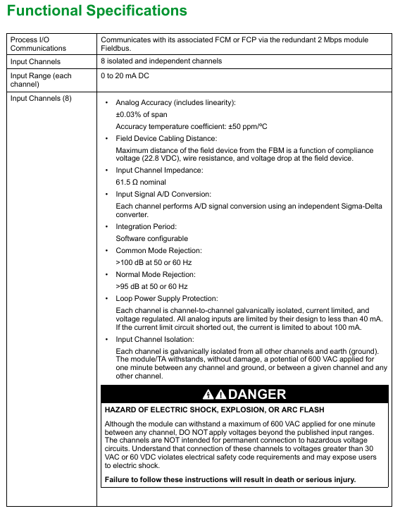
Belonging to the Compact 200 Series I/O subsystem (see document PSS 41H-2COV for details), it has 8 independent analog input channels, each supporting a 2-wire 0-20 mA DC input, enabling interface conversion between on-site sensor signals and FCP (Field Control Processor).
Electrical compatibility with standard HART signals, suitable for the acquisition and transmission of analog signals in industrial automation scenarios.
2. Key characteristics
Specific content of characteristic categories
Isolation performance: Galvanic isolation is achieved between each analog input channel and other channels or ground to avoid signal interference
The accuracy guarantee adopts sigma delta data conversion technology (single channel independent conversion), generating a new reading every 25ms; Support configurable integration period for filtering out process noise and power line frequency noise (improving accuracy through average output)
Compact rugged design with environmental adaptability and physical protection of ABS shell; Adapt to G3 level (harsh) environments defined by ISA Standard S71.04
Easy to maintain installation on the Compact 200 series base plate, fixed with 2 screws; Support hot plugging (no need to remove on-site device wiring, power or communication cables when replacing modules)
The front of the status monitoring is integrated with red/green LED indicator lights, which intuitively display the operating status of the module
Detailed specification parameters
1. Functional specifications
Specification category specific parameters
The communication interface communicates with the associated FCM (fieldbus communication module) or FCP through a redundant 2 Mbps module fieldbus; Support A/B dual path switching, automatically switching to the active path in case of single path failure
Input protection current limit: conventional design ≤ 40mA, short circuit ≤ 100mA; withstand 600VAC (1 minute, not long-term applicable); Prohibited access to voltages greater than 30VAC/60VDC (violating electrical safety regulations and posing a risk of electric shock)
Power requirement input voltage: 24 VDC redundant input (+5%/-10% fluctuation tolerance); Power consumption: 7W; heat dissipation: 4W
The calibration requirement module and terminal components (TA) do not require calibration, reducing maintenance costs
Compliance Certification – EMC: Complies with the European EMC Directive (2004/108/EC (before April 20, 2016), 2014/30/EU (after April 20, 2016)), meets EN61326-1:2013 Class A (emission) and industrial immunity level
-Product safety: UL/UL-C certification (applicable to Class I Groups A-D, Division 2, T4 enclosure systems); The communication circuit meets the Class 2 requirements of NFPA 70 Article 725 and CSA C22.1 Section 16; ATEX 2014/34/EU certification (DEMKO Ex nA IIC T4, applicable to Zone 2 enclosures)
Pollution level meets EIA Standard 364-65 Class III testing, compatible with ISA S71.04 G3 environment without additional requirements
Vibration 0.75g (frequency range 5~500Hz) No additional requirements
Note: The environmental limits of the module can be enhanced by the type of enclosure, and reference should be made to the corresponding product specification sheet (PSS) for the enclosure.
3. Physical specifications
(1) Installation and Dimensions
Installation method and size of components (nominal)
The Compact FBM201 module is installed on the Compact 200 series 16 slot horizontal base plate; The base plate supports DIN rail installation or 19 inch rack installation (requires installation kit) with a height of 130mm (5.12in); Width: 25mm (0.98in); Depth: 150mm (5.9in) (139mm/5.46in with baseboard connector)
Terminal assembly (TA) installed on DIN rail (compatible with 32mm/1.26in, 35mm/1.38in specifications) compression type TA (RH916XG): total width 125mm (reference); Circular terminal block TA (P0917JK): 72mm height above DIN rail (reference), see document page 13 for details
(2) Weight and part number
Part weight and part number
Compact FBM201 module weighs approximately 185g (6.5oz)-
TA (compression type) approximately 181g (0.40lb) RH916-XG
TA (ring terminal type) approximately 249g (0.55lb) P0917J-K
(3) Wiring and cables
TA wiring specifications:
Compression type: Supports solid/multi strand wires (0.5~4mm ²/22~12AWG), multi strand wires with ferrorules (0.2~2.5mm ²/24~12AWG)
Ring terminal block type: supports 0.2-4mm ² wire, compatible with # 6 specification connector (0.375in/9.5mm), with or without plastic sleeve
terminal cable:
Specific requirements for cable parameters
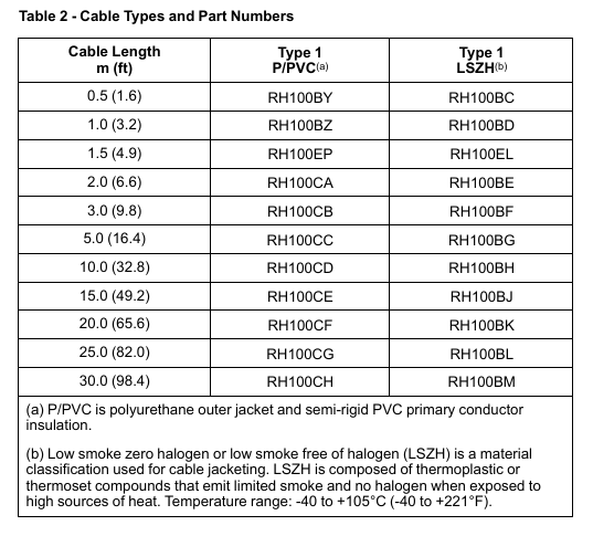
The longest length is 30m (98ft)
Material options include polyurethane (P/PVC) or low smoke halogen-free (LSZH) (LSZH temperature range -40~+105 ℃/-40~+221 ° F)
Type 1 (see Table 2 in the document for details), interface: 37 pin D-subminiature on the motherboard end, 25 pin D-subminiature on the TA end
Part number example polyurethane Type1 (0.5m: RH100BY; 30m: RH100CH); LSZH Type1(0.5m:RH100BC;30m:RH100BM)
Terminal Component (TA) and Cable Details
1. TA type and certification
TA type material certification type certification content
Compression screw type polyamide (PA, -20~+70 ℃ tolerance) Type 1 UL/UL-C Class I Groups A-D Division 2 T4; DEMKO Ex nA IIC T4(Zone 2)
Ring terminal block type polyamide (PA) Type 1, Type 2 Type 1: Same as above; Type 2: UL/UL-C Class I Groups A-D Division 2 associated devices; DEMKO Zone 2 associated devices; Class 2 Limited Energy (60VDC/30VAC/≤ 100VA, user equipment must comply with Class 2)
All TAs comply with UL/UL-C standard for fire and electric shock prevention in ordinary places, as well as the European Low Voltage Directive.
2. Cable Selection Table (Table 2)
Cable Length Polyurethane (P/PVC) Type1 Part Number LSZH Type1 Part Number
Positioning: Mature heavy-duty gas turbine, designed for efficient and flexible power production, suitable for multi scenario energy needs, and can be used as the core equipment of single cycle or combined cycle power plants.
Core values: Low unit kilowatt investment cost, wide fuel adaptability, flexible operation, low maintenance cost, long service life, fast investment return, and fleet reliability exceeding 99%.
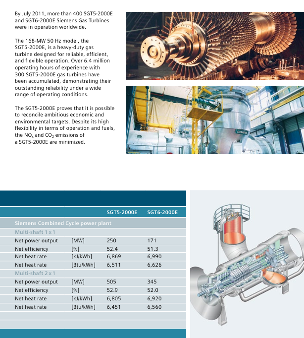
Market performance: As of July 2011, over 400 units have been delivered globally with a total operating time of approximately 9 million hours. Among them, the SGT5-2000E standalone model has accumulated over 6.4 million hours of operation, verifying its stability.
2. Key performance parameters (ISO standard conditions, natural gas fuel, gross value)
1 × 1 configuration: SGT5-2000E with a net output of 250MW and an efficiency of 52.4%; SGT6-2000E has a net output of 171MW and an efficiency of 51.3%.
2 × 1 configuration: SGT5-2000E with a net output of 505MW and an efficiency of 52.9%; SGT6-2000E has a net output of 345MW and an efficiency of 52.0%.
Core design features
1. Infrastructure design
Core configuration: Single shaft and single cylinder design, dual rotor bearings, cold end driven generator, disc rotor (with Hess serrated connection and center pull rod bolt).
Core components:
Compressor: SGT5-2000E has 16 stages, SGT6-2000E has 17 stages; Variable pitch inlet guide vanes, supporting operation at loads as low as 50% and stable exhaust temperature.
Turbine: A 4-stage structure, with the first 3 stages of stationary blades and the first 2 stages of moving blades cooled by convective air. The first 3 stages of the turbine are coated with special materials and do not have film cooling (suitable for dusty fuels).
Combustion chamber: Double silo structure with ceramic insulation cover, 8 burners per chamber for SGT5-2000E and 6 burners per chamber for SGT6-2000E, supporting dry low NOx technology.
2. Core advantageous features
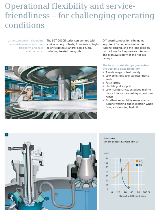
Fuel flexibility: Suitable for both gaseous (natural gas, low calorific value gas, synthetic gas) and liquid fuels (fuel oil, heavy oil, crude oil, naphtha, kerosene), including specialized burners for unconventional fuels.
Operational flexibility: Fast start-up (accelerating to full load within 4 minutes), low emissions under partial load, support for flexible grid regulation, adaptable to special power plant scenarios such as IGCC.
Convenience of maintenance: Manholes are installed inside the combustion chamber for easy inspection of hot aisle components; The dynamic/static blades can be replaced separately (without disassembling the rotor); Ash fuel is easy to clean and inspect during operation.
Environmental performance: Adopting a premixed burner, NOx and CO ₂ emissions are minimized, and low emission levels can still be maintained under partial load.
Core design details and technological advantages
1. Overall structural design
Core configuration: Single shaft and single cylinder design, supported by dual rotor bearings, with the cold end (compressor end) driving the generator to avoid high temperature losses and maintenance risks caused by the hot end driving.
Rotor design: The disc rotor structure is fixed to the central pull rod bolt through Hirsh serrations, ensuring that the rotor components self align during steady-state and transient operation, thereby improving operational stability; Internally designed air circulation channels to minimize thermal stress and support quick start stop.
Modular design: The device structure has a high degree of modularity, making it easy to transport, install, and maintain. It can be flexibly combined and configured according to project requirements.
2. Technical analysis of key components
(1) Compressor
Level configuration: SGT5-2000E has 16 levels, SGT6-2000E has 17 levels; Provide a modified version of a 17 stage compressor for non air integrated synthesis gas/IGCC applications.
Core features: Variable pitch inlet guide vanes (VIGV), capable of maintaining a constant exhaust temperature at loads as low as 50%, and adapting to flexible load regulation requirements; The dynamic/static blades adopt a free standing design, optimized by frequency modulation, and can operate continuously at full load within a wide frequency offset range.
(2) Turbine
Structural parameters: 4-stage turbine design, with convective air cooling technology used for the first 3 stages of stationary blades and the first 2 stages of moving blades, suitable for high-temperature working environments; The first three stages of turbine blades are covered with special coatings to enhance their high temperature resistance and corrosion resistance.
Adaptation design: No gas film cooling structure, avoiding cooling channel blockage caused by ash accumulating fuels (such as heavy oil and crude oil), and expanding the fuel adaptation range.
(3) Combustion chamber
Structural form: Double silo type large volume combustion chamber with ceramic insulation cover, reducing the impact of direct flame radiation on turbine blades and extending component life.
Burner configuration: 8 burners per combustion chamber for SGT5-2000E, 6 burners per combustion chamber for SGT6-2000E; Adopting a hybrid burner and dry low NOx technology, the premixed combustion design reduces emissions.
Maintenance advantage: There is a manhole on the side of the combustion chamber, which can directly inspect the hot channel components from the burner to the turbine blades without disassembling the overall structure, improving maintenance convenience.
3. Three core advantageous characteristics
(1) Fuel flexibility: adaptable to multiple types of fuels, reducing fuel dependence
Gaseous fuels: standard natural gas, low calorific value natural gas, synthesis gas (IGCC output), naphtha derived gas, etc.
Liquid fuels: standard fuel, heavy oil, crude oil, kerosene, naphtha, and ash based fuels.
Adaptation technology: Provide specialized modified burners for unconventional fuels such as synthesis gas and heavy oil to ensure combustion stability and efficiency; Siemens has accumulated rich experience in unconventional fuel applications and can provide customized solutions for projects.
(2) Operational flexibility: adaptable to complex working conditions, fast response
Quick start stop: With standard static excitation and variable frequency starting system, it can accelerate from start-up to full load within 4 minutes, meeting the needs of power grid peak shaving, emergency power supply, etc.
Load regulation: Supports flexible adjustment of 50% -100% load, and can maintain low emission levels even under partial load, adapting to power grid load fluctuations.
Grid adaptation: With flexible grid support capabilities, it can adapt to different regional grid frequency requirements (50Hz/60Hz) and has strong stability.
(3) Maintenance convenience: reduce operation and maintenance costs, extend service life
Component replacement: All stationary and moving blades of the compressor and turbine can be replaced separately without disassembling the rotor and lower cylinder body, reducing maintenance downtime.
Inspection channel: A manhole is installed inside the combustion chamber, and the hot channel components (burner, turbine blades) can be directly inspected without disassembling the equipment.
Special adaptation: Design a structure that is easy to manually clean and inspect for the operation scenario of greyed fuel, reducing the impact of greying on equipment performance.
Lifespan design: The core components are made of high wear-resistant and high-temperature resistant materials, combined with optimized cooling and coating technology, to extend the service life of the components and reduce replacement frequency.
(4) Environmental performance: Low emission design, in compliance with environmental standards
Emission control: Using dry low NOx combustion technology and premixed burners, NOx emissions can be maintained at a low ppm level under ISO conditions, and even partial load operation can meet strict environmental requirements.
Energy saving design: High cycle efficiency reduces CO ₂ emissions per unit of power generation, while optimized combustion chamber and turbine design reduces fuel waste and improves energy utilization efficiency.
Application scenarios and delivery solutions
1. Main application areas
(1) Power industry
Single cycle power station: suitable for emergency power supply, peak shaving power stations, or projects with abundant natural gas resources and sensitive investment costs.
Combined Cycle Power Plant: Composed of 1 × 1 or 2 × 1 multi axis configurations, it forms a large-scale and efficient power plant suitable for main power supply, with an efficiency of up to 52.9% (SGT5-2000E 2 × 1 configuration).
IGCC power station: suitable for use as gas fuel and can be integrated with coal based IGCC systems, such as the Buggenum project in the Netherlands, to achieve efficient and clean power generation.
(2) Oil and gas industry
Compressor Drive: Used for direct mechanical drive of compressors in liquefied natural gas (LNG) production, or as a fully electric generator version adapted for power supply in oil and gas extraction sites.
Special chemical scenarios: suitable for gas to liquid (GTL) factories, synthesis gas production factories, etc., supporting unconventional fuels such as low calorific value gas and synthesis gas.
2. Delivery and Configuration Plan
(1) Standard Delivery Package (SGT-PAC Module)
Core equipment: gas turbine, electrical generator.
Control and Electrical: Instrumentation and Control Systems, Electrical Equipment, Power Control Centers, Start Up VFDs.
Safety and protection: soundproof enclosure, fire protection system.
Delivery features: Most equipment is pre assembled and delivered, including a large number of prefabricated pipelines and wiring, auxiliary system grouping and integration, significantly shortening the on-site installation and commissioning cycle, and reducing project implementation costs.
(2) Optional configurations (partial list)
Fuel related: liquid fuel system, dual fuel operation system, heavy oil operation adaptation, synthesis gas operation adaptation.
Air intake treatment: intake evaporative cooling system, intake anti icing system, intake self-cleaning pulse filter.
Exhaust and smoke exhaust: Single cycle gas turbine chimney, combined cycle bypass baffle and bypass chimney.
Cooling and noise reduction: Generator and lubricating oil finned fan cooling system, enhanced noise reduction configuration.
3. Analysis of typical project cases
Project Location Operating Party Project Scale and Configuration Fuel Type Operating Performance Core Highlights
The Buggenum Nuon Power Buggenum 290MW IGCC power station in the Netherlands features a 1 × 1 single axis combined cycle system, with one SGT5-2000E synthesis gas (main) and natural gas (backup) operating for over 80000 hours to adapt to IGCC scenarios. The dual fuel system ensures stable power supply
Transfield Pty Ltd 150MW single cycle power station in Townsville, Australia, with one new generation SGT5-2000E natural gas operating for over 35000 hours of peak shaving and emergency power supply, has started fast
Az Zour, Kuwait Ministry of Electricity and Water Resources 960MW single cycle power station, with 8 SGT5-2000E natural gas and fuel oil (dual fuel) units operating for over 170000 hours in a large-scale cluster configuration, suitable for areas with abundant oil and gas resources
Taiwan, China Xingda Taiwan Electric Power Company 2200MW combined cycle power plant (the world’s largest 60Hz power plant), including multiple Siemens gas turbines with natural gas running more than 900000 hours in total, large-scale combined cycle application, efficient and stable power supply
Version size range, operating system core differences
Comfort V1 4 “-22” Windows CE 6 with dual audio sockets and Mini-B USB interface
Comfort V1.1 7 “-12” Windows CE 6 with audio output only, Mini-B USB interface
Comfort V2 15 “-22” Windows Embedded Compact 2013 without Mini-B USB interface, performance improvement
3. Core hardware features
Display screen: 16 million color TFT widescreen, resolution 480 × 272 (4 “) -1920 × 1080 (22”), backlight life 30000-80000 hours
Communication interface:
PROFINET:10/100Mbps(4″-12″)、10/100/1000Mbps(15″-22″), Support circular topology
PROFIBUS DP: Maximum transmission rate of 12Mbps, RS422/485 interface
USB: Type A (peripheral devices), Mini-B (debugging, V2 not available)
Protection level: IP65 on the front (after installation), IP20 on the back
Safety regulations and usage restrictions
1. Warning level and meaning
Example scenario of warning sign meaning
Danger (DANGER) Failure to take measures may result in death/serious personal injury. When the cabinet is electrified, it may open and come into contact with lethal voltage
Warning: Failure to take measures may result in death/serious personal injury. In explosion-proof areas, live plug and unplug connectors may cause explosions
Caution (CAUTION) Failure to take measures may result in minor personal injury, sharp objects scratching the touch screen
Caution: Failure to take measures may result in property damage, failure to follow the connection sequence, and equipment damage
2. Key safety requirements
Electrical safety: Only supports 24VDC power supply (voltage range 19.2V-28.8V) and must comply with SELV/PELV circuit requirements (IEC/EN 61131)
Use in explosion-proof areas:
Only Ex certified models are available for Zone 2/22 zones
Do not plug or unplug connectors or memory cards with power on
Ensure that the plug is secure against loosening (such as fixing the USB interface with a cable tie)
Environmental restrictions:
Only for indoor industrial use, prohibited for use in residential areas
Avoid high radio frequency interference (such as mobile phones), corrosive gases, and strong electromagnetic radiation
Material thickness of 2mm-6mm ensures protection level of IP65
The heat dissipation gap should be ≥ 15mm on both sides, ≥ 50mm on the top and bottom, and ≥ 10mm on the back to avoid equipment overheating
Installation tilt angle: horizontal ± 35 °, vertical ± 35 ° (touch only). The 7 “-15” model can be extended to 40 ° under specific conditions
2. Connection sequence and specifications
Equipotential bonding: Use copper/galvanized steel wires with a cross-sectional area of ≥ 16mm ², and the wire between the grounding bar and the equipment should be ≥ 4mm ²
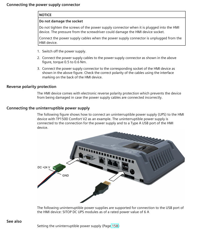
Power connection:
The power plug supports a maximum of 1.5mm ² wire and a torque of 0.5-0.6Nm
Equipped with reverse polarity protection to prevent damage to equipment caused by reverse connection
Controller connection:
Support SIMATIC S7-200/300/400/1200/1500 and third-party controllers (such as Allen Bradley)
PROFINET requires a unique device name to be configured, and PROFIBUS requires a bus address (1-126) to be set
Peripheral device connection:
USB devices (mouse/keyboard/printer): wire length ≤ 1.5m, USB 2.0 or above certification
Audio equipment: Connected through Line Out interface, production environment requires shielded cables
Network settings: IP address (static/DHCP), PROFINET device name, NTP time synchronization
Security mode: Password protected control panel to prevent unauthorized modifications
2. Service and maintenance functions
Key points of functional operation
Backup/restore supports WinCC or ProSave tools, backup file format *. psb, including project, recipe, license
OS updates require external storage media or configuration PC, and automatic backup must be disabled before updating to avoid data loss
Automatic backup activated after inserting the system storage card, real-time synchronization of device data, and can be restored by inserting a replacement device in case of failure
Touch screen calibration uses a touch pen to calibrate 5 points, confirm and save within 30 seconds to ensure precise operation
Project commissioning and operation
1. Project transmission and testing
Transmission method:
Manual transmission: Select “Download to device” through WinCC and configure PROFINET/Ethernet channels
Automatic transmission: Used during debugging phase, it is recommended to disable it after commissioning to avoid accidental triggering
Test type:
Offline testing: Communication without controller, verifying interface layout and operational logic
Online testing: Connect the controller to verify measurement value updates, alarm triggering, and communication stability
2. Core operational functions
Numerical input:
Touch sensitive: Pop up on-screen keyboard (alphanumeric/pure numeric), supports range verification
Key press: System key press the phone keyboard logic input, long press to enter numbers
Function key operation:
Global function key: Effective for all projects (such as alarm confirmation)
Local function keys: only effective for the current screen (such as switching between sub screens)
Language switching: Supports up to 32 languages, requires configuration of corresponding operating components, and takes effect immediately after switching
Maintenance and Technical Specifications
1. Daily maintenance requirements
Cleaning: Turn off the power or lock the touch screen, wipe with a cloth dipped in neutral cleaner, and avoid solvents such as compressed air and alcohol
Spare parts replacement: Only use Siemens certified spare parts (such as assembly clips, memory cards), and contact official technical support for any malfunctions
Recycling and disposal: processed by compliant electronic waste recycling enterprises, in compliance with local environmental regulations
2. Key technical parameters (taking TP1500 Comfort V2 as an example)
Project specifications
Display screen with 15 “TFT, 1280 × 800 resolution, 16 million colors, backlight life of 50000 hours
Communication interface 2 x PROFINET (1 x 10/100Mbps, 1 x 10/100/1000Mbps), 1 x PROFIBUS DP
Power supply 24VDC, current 1.7A (load related 1.45-2.1A), power 41W
Working temperature 0-50 ℃ (horizontal), 0-40 ℃ (inclined at 35 ° C)
Protection level: IP65 on the front and IP20 on the back
Product positioning: HMI devices designed for mid to high end industrial applications, featuring high-resolution display, multi protocol communication, flexible expansion, and supporting functions such as alarm, formula management, trend display, and multi language switching. Some models are suitable for special scenarios such as explosion-proof, outdoor, and food hygiene.
Model classification:
By operation mode: button type (KP series), touch type (TP series), button+touch composite type (KTP series)
According to the display screen size: 4 “, 7”, 9 “, 12”, 15 “, 19”, 22 “, different sizes correspond to different installation sizes and hardware specifications
According to hardware versions: Comfort V1, V1.1, V2, the differences are reflected in the operating system (Windows CE 6/Embedded Compact 2013), interface configuration, etc
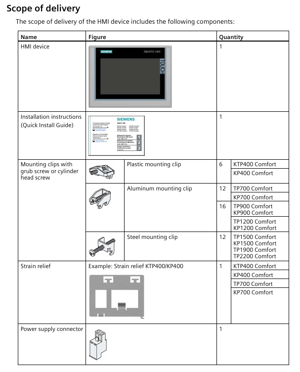
Standard kit: includes HMI device, installation instructions, assembly clips (quantity varies with model), power plug, strain gauges (some models).
Optional accessories: including RS422/RS232 adapter, PROFIBUS bus connector, protective film, SIMATIC HMI memory card, USB hub, etc., need to be ordered separately.
2. Safety regulations and usage restrictions
Security level: Clearly define the four levels of “danger”, “warning”, “caution”, and “attention” warnings. The back of the equipment is designed to be open and needs to be installed in a locked cabinet. Only authorized professionals are allowed to operate it.
Usage environment:
Mainly for industrial applications, in compliance with EN 61000 series electromagnetic compatibility standards, some models support use in explosive hazardous areas (Zone 2/22)
Prohibited for use in residential areas, mixed use areas must comply with RF interference restrictions (EN 55011 Class B)
Operating temperature range: 0 ° C-50 ° C (conventional), some models can be extended to -20 ° C-60 ° C (storage), and a heat dissipation gap needs to be reserved
Electrical safety: Only supports 24VDC power supply (voltage range 19.2V-28.8V), with reverse polarity protection. It is prohibited to plug or unplug connectors with power in explosive areas.
3. Installation and connection process
(1) Installation preparation
It is necessary to check the integrity of the packaging and confirm the environmental conditions (temperature, humidity, air pressure). The installation opening should match the equipment size (material thickness 2mm-6mm, surface roughness ≤ 120 μ m) to ensure the protection level (IP65 on the front and IP20 on the back).
Reserved heat dissipation gap: left and right ≥ 15mm, up and down ≥ 50mm, back ≥ 10mm, supports horizontal/vertical installation (some models), maximum tilt angle ± 35 °.
(2) Installation steps
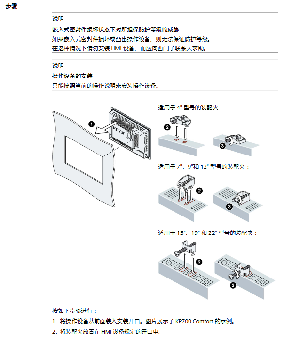
Insert the device into the installation opening from the front and secure it with the matching assembly clip (torque: 4 “model 0.2Nm, 7” -22 “model 0.5Nm), ensuring that the embedded seal fits snugly without distortion.
The function keys need to be marked with a dedicated marker strip (thickness 0.15mm, direct writing is prohibited), and the template can be obtained through the official website or WinCC installation directory.
(3) Connection specifications
Connection sequence: equipotential bonding → power supply → controller → configuration PC → peripheral devices (USB devices, printers, etc.)
Can communicate with SIMATIC S7-200/300/400/1200/1500, third-party controllers (such as Allen Bradley, Modicon)
USB interface (Type A for peripheral devices, Mini Type B for debugging), audio output interface (some models)
Equipotential bonding: Copper or galvanized steel wires with a cross-sectional area of ≥ 16mm ² should be used, and the cross-sectional area of the wire between the grounding bar and the equipment should be ≥ 4mm ².
4. Equipment debugging and system configuration
(1) Basic debugging
Memory management: Supports memory, SD/MMC memory cards, USB storage media, and system memory cards (≥ 2GB) can achieve automatic backup and fast fault recovery.
Safe mode: Protect the control panel and taskbar with a password to prevent unauthorized modifications.
(2) Network and Communication Configuration
Support DHCP automatic allocation or static IP settings, PROFINET device names must be unique and comply with the DNS protocol.
Configurable MPI/PROFIBUS DP parameters (bus address, transmission rate), NTP time synchronization, proxy server, email configuration, Telnet remote control, etc.
(3) Service and maintenance functions
Backup and Recovery: Supports backing up projects, recipes, user data, etc. through WinCC or ProSave, with a backup file format of *. psb.
Operating system update: It can be updated through external storage media or configuration PC. Before updating, the automatic backup function must be disabled to avoid data loss.
Automatic backup: can be activated after inserting the system storage card, real-time synchronization of device data, and quick recovery in case of failure.
5. Project implementation and operation
(1) Project transmission and testing
Transmission method: Supports manual/automatic transmission from the configuration PC, or loading projects through external storage media. Automatic transmission is suitable for the testing phase and is recommended to be disabled after debugging is completed.
Operation mode: divided into three modes: offline (communication without controller), online (communication with controller), and transmission (project transmission/data backup), which can be switched through project configuration operation elements.
Test types: offline testing (verifying interface and operation), online testing (verifying communication and functionality), which requires checking screen layout, navigation, input objects, measurement value updates, etc.
(2) Project Operations
Operation mode: Touch screen (sharp objects are prohibited from touching), device keyboard, external USB keyboard/mouse, supporting single touch, function key operation, and numerical input (numbers/alphanumeric).
Core operations: language switching (up to 32 languages), function key operations (global/screen specific functions), direct keys (quick control of PLC I/O bits), information text viewing, project closure, etc.
Numerical input: The on-screen keyboard automatically pops up, supporting range verification and decimal filling. Exceeding the limit will trigger an alarm and reject input.
6. Maintenance and troubleshooting
(1) Daily maintenance
Cleaning: After turning off the power or locking the touch screen, wipe it with a cloth dipped in neutral cleaner. Do not use compressed air or corrosive solvents.
Repair: Only Siemens approved spare parts are allowed. In case of malfunction, contact official technical support and provide information such as equipment model and image version.
Recycling: It must be processed by certified electronic waste recycling companies and comply with local environmental regulations.
(2) Common fault handling
System memory card error: Check if the memory card is compatible (≥ 2GB SIMATIC HMI memory card), replace the faulty memory card.
Communication failure: Verify IP address/bus address uniqueness, cable connection and shielding, controller model compatibility.
Touch screen unresponsive: recalibrate the touch screen and check for physical damage.
7. Core parameters of technical specifications
Display specifications: 16 million color TFT widescreen, resolution of 480 × 272 to 1920 × 1080, backlight life of 30000-8000 hours (varies by model).
Communication performance: PROFINET has a maximum transmission rate of 1000Mbps, PROFIBUS DP has a maximum speed of 12Mbps, and supports secure HMI communication (TIA Portal V17 and above).
Software features: WinCC supports up to 750 images, 6000 discrete alarms, 500 recipes, and supports VBScript extension, data archiving (CSV/RDB/TXT format), and user permission management (up to 50 user groups).
Protection level: IP65 on the front and IP20 on the back, in compliance with IEC 60529 standard.
Key precautions
Strictly follow the requirements for heat dissipation and protection during installation, otherwise it will affect the lifespan of the equipment and the effectiveness of certification.
When used in explosive hazardous areas, it is prohibited to plug and unplug connectors and storage cards with power on, and it is necessary to ensure that the plugs are not loose.
Before transferring the project, it is necessary to confirm that the device firmware is compatible with the WinCC version. Updating the operating system will clear all data, so it is important to backup in advance.
Network configuration should avoid IP address conflicts, and PROFINET device names and computer names should be configured separately.
Touch screen calibration requires the use of a stylus or fingers to avoid damage caused by sharp objects.
Implement motor start stop: supports regular start stop (dependent on P1120 ramp up time, P1121 ramp down time) and quick stop (dependent on P1135 OFF3 ramp down time).
Set value transmission: Loop the speed set value in the form of percentages from * * -100% to+100% * *, and any changes will take effect in real-time.
Status feedback: Output signals such as motor rotation direction (O-Right/O-Left), actual frequency (O-Actual_frequency, range -100% to+100%), and shutdown status (O-STOP).
Automatic debugging
Batch/Replacement Scenario Adaptation: When debugging multiple MM4 units in bulk or replacing a single faulty unit, there is no need for PG/PC or professional debugging software. The PLC can automatically complete the parameter configuration of the new MM4.
Simplified debugging process: including quick debugging (P0010=1), motor recognition (requires motor cold state), and saturation characteristic recognition (only supported by MM440).
parameter management
Full parameter read and write: Read and write all parameters of MM4 through PKW communication, and the OP (operation panel) only supports parameter reading.
Parameter backup: Store the debugged parameters in the PLC’s parameter DB (data block) for easy recovery in the future.
Diagnostic function
Multi dimensional error monitoring: covering MM4 faults/alarms, Profibus DP errors, parameter transmission errors, and automatic debugging errors.
Historical data recording: stores the latest and historical fault/alarm information (such as the fault codes and values of the last 3 faults), supports fault reset (I_RESET_Corr).
Controller SIMATIC S7 300 (CPU 313-2DP and above) S7 400、C7、SINUMERIK
3.2 Not Applicable Devices and Limitations
Not applicable to controllers: SIMATIC S7 200, SIMATIC S5.
Function limitation: The system does not monitor whether the startup signal (I_Enable) meets safety conditions, and users need to provide additional protection in the program.
Installation and configuration process
4.1 Scenario without Drive ES Basic and Starter
Hardware configuration: Set the Profibus DP address of MM4 (no need to reset to factory settings).
HW Config operation:
Start HW Config in Step 7 and configure PLC hardware.
Select “MICROMASTER 4” in the “PROFIBUS-DP/SIMOVERT Catalog” and specify the DP address.
Select slot 1 and configure PPO type as PPO1 (4 PKW+2 PZD).
Program loading:
Save and compile HW Config, download to PLC module.
Copy the program blocks and symbol table from the functional block example to the user program, adapt them, load them into the PLC, and start them.
Debugging startup: Call the MM4 diagnostic interface of OP to troubleshoot DP errors, enter the debugging interface to enter motor data, start automatic debugging (set I2 Enable=0, I2 Enable QC=1, IOU_ Parameters=1), and execute motor recognition after completion.
4.2 Scenarios with Drive ES Basic and Starter
Hardware configuration: Follow step 1 of section 4.1 to set the DP address of MM4.
HW Config operation:
Configure PLC and MM4, select the corresponding MM4 version (refer to the equipment nameplate, such as “A01/2.05” corresponding to version 2.0x).
Pre allocate PPO type as PPO1 (PKW+PZD-2/2), fill in the I/O address of MM4 (PKW starting address, PZD address is PKW address+8).
Program and OP adaptation:
Load the program block and symbol table in step 3 of section 4.1.
Install OP project and adapt to “MM4” and “ParameterDB” text lists.
Debugging startup: The first debugging can be completed through Starter, and the parameters can be entered into the parameter DB; or the OP debugging interface can be directly called, and the subsequent process is the same as step 4 in 4.1.
Detailed explanation of key functions
5.1 Definition of Control and Feedback Signals
Parameter Name Type Direction Unit/Range Description
The starting I/O address of the PKW area configured in the I-Address INT IN – HW Config
I-Enable BOOL IN – Variable frequency drive enable signal, can only be set when O-Drive-ready=1
I-Fast-STOP BOOL IN – Fast Shutdown Signal: 0=Fast Shutdown (using P1135), 1=Normal Shutdown (default can be set to 1)
Setpoint INT IN -100~+100 speed setting value (percentage)
Actual operating frequency INT OUT -100~+100 (percentage)
O-Drive-ready BOOL OUT – Inverter ready signal: must meet the requirements of “shutdown, I-Fast-STOP=1, no faults, no debugging in progress”
O-Fault BOOL OUT – MM4 fault signal (excluding data transmission errors)
O-Data_ error BOOL OUT – Parameter transmission/automatic debugging error signal
IOU_ Parameters BOOL IN/OUT – Start automatic debugging signal (user set 1 to start, clear 0 after FB is completed)
5.2 Automatic Debugging Process
5.2.1 Parameter DB adaptation
Motor data area: Enter the required parameters for quick debugging (P0010=1), using motor dataset 0 by default; Multiple parameter DBs need to be created for multiple datasets, which can be specified through Z_Sotor_data_SBNr.
Technical data area: Enter other parameters that are not quick debugging, support sub parameters (sub parameter 0 is the first, such as data [2] indicating the presence of sub parameters 0 and 1), and match the data type of the parameters.
5.2.2 Parameter input method
Operation steps for input method
Method 1: The frequency converter has been debugged and set to I2 Enable=0 and I2 Enable QC=1;
2. Set IOUR_Parameters=1 to start data reading;
3. O-Data_transfer_running=1 indicates that the transfer is in progress, and after completion, IOUR_Parameters will automatically clear 0.
Method 2: 1. Enter parameters directly on the OP interface (only display the parameters that need to be changed);
2. Use initial values for other parameters and support leaving the DB list empty (for easy OP indirect addressing).
5.2.3 Automatic Debugging Steps
Restore MM4 to factory settings.
Perform quick debugging (transfer motor data area parameters).
Transmission technology data area parameters.
Save the parameters to the EEPROM of MM4.
After debugging is completed, perform motor identification (ensuring that there are no errors during debugging and the motor is in a cold state).
5.3 Parameter transmission mechanism
Communication method: Based on PKW communication, it supports three parallel parameter read/write requests (Job_1~Job_3), which are executed in the order of Job_1 → Job_2 → Job_3.
Request block structure (taking Job_1 as an example):
|Parameter Name | Type | Initial Value | Description|
|Job_1. Parameter-N | INT | 0 | Target parameter number (e.g. 1002 represents fixed frequency 2)|
|Job_1. Index | INT | 0 | Sub parameter number (set 0 when there is no sub parameter, set the last sub parameter number when there are multiple sub parameters)|
|Job_1. Identifier | Byte | B # 16 # 0 | Operation type: 1=Read single parameter, 2=Write RAM, 3=Write EEPROM, 11=Read multiple sub parameters, etc|
|Job_1. Value_2~2 | DINT | L # 0 | Transferred parameter values (used as needed, such as using only Value_0 for a single parameter)|
Control signal: Job.RWRequest_1~3 are request trigger signals (user set 1 to start, clear 0 after FB is completed); Data_fault.Job.RWRequest_1~3 are error signals corresponding to the requests.
5.4 Diagnostic mechanism
5.4.1 Classification of Error Sources
Malfunctions/alarms of MM4 (such as overcurrent and overvoltage).
Fault of standard FC (SFC14/SFC15).
The functional block itself is malfunctioning.
Parameter transmission and automatic debugging errors.
5.4.2 Key diagnostic signals and displays
Parameter Name Type Direction Description
When there is an alarm for O-Warning BOOL OUT, it is 1
O-Fault BOOL OUT MM4 fault is 1 (excluding data errors)
Resetting signal: clearing MM4 fault and data error display, interrupting debugging process (without interrupting parameter transmission)
Data_fault.Nr. INT STAT error number (e.g. 0=illegal parameter number, 17=request execution not allowed in running state)
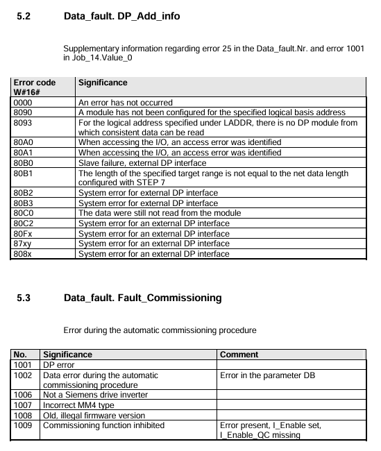
Data_fault.DP_Add_info HEX STAT DP error details (e.g. 8090=no module specified address, corresponding to SFC14/SFC15 error)
Error code description
6.1 Data_fault.Nr. (Parameter transmission and debugging errors)
Error Number Meaning Remarks
0 Illegal Parameter Number (PNU) parameter does not exist in MM4
The parameter value cannot be modified. This parameter is a monitoring type parameter and can only be read
17. Due to operational status, the task cannot be executed. The current MM4 status does not support this request (such as changing motor data during operation)
25 DP error needs to be viewed in conjunction with Data_fault.DP_Add_info for details
Parameter number 1001 is currently not activated and depends on the running status of MM4. It can be operated after activation
6.2 Data_fault.DP_Add_info (DP Error Supplement)
Meaning of Error Code (W # 16 #)
8090 specifies logical address without configuration module
80A0 recognized access error while accessing I/O
The target range length of 80B0 does not match the network data length configured in Step 7
6.3 Data_fault.Fault_Commission
Error Number Meaning Remarks
1001 DP error needs to be investigated for Profibus DP connection and address configuration
1002 automatic debugging data error parameter DB has errors (such as parameter values exceeding the range)
1007 MM4 model incorrectly configured MM4 model does not match the actual connected device
Concentrating on the essentials – the new Basic Panels
Today, visualization is part of the standard repertoire for most machines. The cost factor plays a crucial role in this case, especially for small machines and simple applications. HMI devices with basic functions are often fully sufficient for simple applications.
This is exactly the demand that we intend to meet – with our new SIMATIC HMI Basic Panels. By concentrating on the essentials, the Basic Panels offer exactly those basic features that are demanded – at the right price. A perfect cost-to-performance ratio.
Like all devices in our product catalog, the new Basic Panels offer proven SIMATIC quality and – regardless of their display dimensions – many software functions as standard: for example, an alarm system, recipe management, trend functionality and language switching.
Users therefore profit from the advantages of visualization, such as improved process quality, even with simple applications.
Equipment Overview and Structure
1. Product positioning and core functions
Positioning: Targeting small machines and simple applications, with the design concept of “focusing on core functions”, balancing cost and performance, providing cost-effective visual solutions.
Standard features: All devices have SIMATIC quality, regardless of display size, with standard software functions such as alarm system, formula management, trend function, language switching, etc., which can improve the process quality of simple applications.
2. Structural details of each device
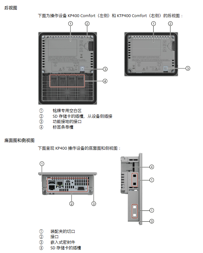
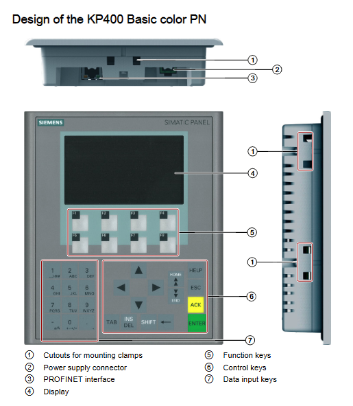
KP300 Basic mono PN: includes power connector, function keys, PROFINET interface, nameplate, display, installation seal, control keys, interface name, installation fixture cut, functional grounding connection, and is a monochrome display keyboard device.
KP400 Basic color PN: Adding data input keys on the basis of KP300, it is a color display keyboard device, which includes function keys such as ACK, TAE, SHIFT, and ENTE, and has an identification bar guiding device.
KTP series (KTP400/600/1000 Basic): All are “touch+function key” combination devices. KTP400/600 supports monochrome/color display, while KTP1000 only displays color. The structure adds a touch screen, and the interface includes PN/DP types. Some models have DIP switches (for RS422/RS485 configuration).
TP1500 Basic color PN: pure touch device, no function keys, only includes PROFINET interface, structure includes fixed components, installation seals, etc., display size is 15 inches.
3. Product packaging and accessories
Package contents:
Required components: HMI device (1 unit), quick installation guide (1 copy), installation seal (1 piece, KTP600 Basic needs to be installed separately, other devices are pre installed), power terminal (1 piece).
Installation fixtures: Configure according to equipment type differences, such as KP300 Basic with 4 plastic fixtures, KP400 Basic with 7 plastic fixtures, KTP400 Basic mono PN with 5 aluminum fixtures, etc.
Core accessory type:
Converter/adapter/connector: such as RS422 to RS232 converter (order number 6AV6671-8XE00-0AX0), PC/PPI cable (6ES7 901-3CB30-0XA0), USB/PPI cable (6ES7 901-3DB30-0XA0), PROFINET RJ45 connector (6GK1901-1BB10-2AA0), etc., clarify the purpose and adaptation scenarios of each accessory.
Clamping frame: such as the clamping frame for 10 “/12” touch devices (6AV6 671-8XS00-0AX0), used for reinforcement when the cutting material for KTP1000 Basic installation is insufficient.
Protective film: Classified by equipment size, such as 4-inch protective film (for KTP400 Basic mono PN, 6AV6 671-2EC00-0AX0), 15 inch protective film (for TP1500 Basic, 6AV6 574-1AD00-4EX0).
Service package: such as 20 plastic fixture sets (6AV6671-8KX00-0AX2), 10 power terminal sets (6AV6671-8XA00-0AX0).
Preparation before equipment installation
1. Packaging inspection and document storage
Inspection requirements: After receiving the equipment, check whether the packaging is damaged during transportation and confirm that the contents are intact (refer to the “Product Packaging” list); If damaged components are found, installation is not allowed and Siemens representatives should be contacted.
Document management: It is necessary to properly keep the accompanying documents, which are part of the equipment and require guidance from the documents for subsequent debugging and maintenance.
2. Confirmation of environmental conditions
Standard reference: It is necessary to familiarize oneself with the standards, certifications, EMC parameters, and technical specifications of the equipment in advance. Relevant information is distributed in “Certificates and approvals”, “Electromagnetic compatibility” “Information on insulation tests, protection class and degree of protection”( Sections such as insulation testing, protection level information, and “Power supply”.
Mechanical and climatic conditions:
Operating environment: It must comply with the mechanical (vibration, shock) and climatic (temperature, humidity, air pressure) parameters specified in the “Conditions of use”, and avoid use in areas with high ionizing radiation, corrosive environments, and strong electromagnetic interference (unless additional measures are taken).
Transportation and storage: It must comply with the IEC 60721-3-3 (3K7 level) storage standard, IEC 60721-3-2 (2K4 level) transportation standard, temperature range -20~+60 ℃, relative humidity 10%~90% (no condensation), and avoid falling (≤ 1m), severe vibration, etc.
3. Installation location selection
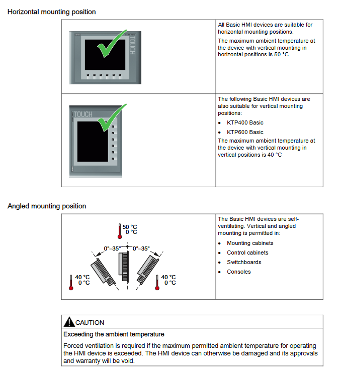
Installation posture:
Horizontal installation: All Basic Panels are supported, with a maximum ambient temperature of 50 ℃.
Vertical installation: Only supported by KTP400 Basic and KTP600 Basic, with a maximum ambient temperature of 40 ℃.
Tilt installation: The equipment is self ventilated and can be tilted (0 °~35 °) in control cabinets, distribution boxes, and control consoles, with a temperature range of 0~40 ℃ or 0~50 ℃ (depending on the equipment type).
Temperature warning: If the maximum allowable ambient temperature is exceeded, forced ventilation is required, otherwise the equipment may be damaged and the equipment certification and warranty will be invalidated.
4. Requirements for installation clearance and incision
Gap requirement: To ensure self ventilation of the equipment, a specific gap (unit: mm) needs to be reserved, as follows:
|Device type | x-direction | y-direction | z-direction|
|KP300 Basic|15|40|10|
|KP400 Basic|/|40|10|
|KTP400 Basic|/|40|10|
|KTP600 Basic|15|40|10|
|KTP1000 Basic|15|50|/|
|TP1500 Basic|15|50|10|
Incision requirements:
Material strength: The material in the incision area should be strong enough to ensure the long-lasting and safe installation of the equipment, avoiding material deformation caused by fixture force or equipment operation.
Protection level guarantee: If the protection level needs to reach IP65 or Type 4X/Type 12 (indoor only), the thickness of the cut material should be 2-6mm (KP300 Basic mono PN is 2-4mm); The deviation of the incision plane is ≤ 0.5mm; the surface roughness of the sealing area is ≤ 120 μ m (R120); If the thickness of the incision material is less than 2mm, an additional clamping frame is required for KTP1000 Basic.
Compatibility: The installation slots of Basic Panels are compatible with some older SIMATIC HMI devices, such as KTP400 Basic compatible with TP 177B 4 “, KTP600 Basic compatible with TP 177A, TP 177B 6”, etc.
Size parameters: When installed horizontally, KP400 Basic has a cutting size of 135 (w) × 171 (h) mm, KTP1000 Basic has a cutting size of 367 × 289mm, etc; When installed vertically, the cut size of KTP400 Basic is 123mm (specific direction), please refer to the dimension diagram in the document for details.
5. Function key identification
Identification rule: Function keys with no available identification for KP300 Basic; Other devices require printable and writable film as identification strips, with a thickness not exceeding 0.15mm. The use of paper identification strips is prohibited, and direct writing of identification on the keyboard is not allowed.
Identification process:
Edit templates on PC, which can be downloaded from the “CD3 \ Documents<language>\ Slides” directory of WinCC/WinCC flexible DVD or Siemens official website.
Print the edited template on the film, and spray a fixed spray film on the identification strip.
Wait for about 5 minutes until the spray is dry and free of stains.
Trim the identification strip and cut its corners into a 45 ° angle for easy insertion.
Insert the identification strip into the guide slot to the end, and the identification strip will extend about 3cm. The template size has been preset, and there is no
Accessories: Installation fixtures for corresponding equipment (aluminum/plastic, quantity according to equipment type), installation seals (if not pre installed).
2. Equipment insertion steps
Seal installation: If the device is not pre installed with a seal, it needs to be inserted into the groove on the back of the front panel of the device to ensure no distortion. Proper installation of the seal is the key to achieving IP65 protection level.
Device embedding: Insert the device into the installation slot from the front, taking care to avoid protruding identification strips getting caught between the slot and the device.
Insert the first fixture into the first position of the back cut of the equipment, and the fixture position should match the corresponding diagram of the equipment in the document.
Tighten the fixture with a No.2 screwdriver, with a maximum torque of 0.2N · m.
Repeat steps 1-2 to install all required fixtures.
If the fixture needs to be installed separately, first insert the set screw and turn it several times, then place the fixture in the corresponding position of the equipment.
Install all plastic fixtures according to the required quantity of equipment, ensuring that the equipment is securely fixed.
Equipment Connection Specification
1. Preparation before connection
Tools and accessories: Prepare a No. 2 Phillips screwdriver, a No. 3 Phillips screwdriver, a TX20 Phillips screwdriver, a crimping tool, power terminals, and a 24VDC power supply (current must meet equipment specifications, refer to the “Power supply” section).
Connection sequence: Strictly follow the order of “equipotential connection → power connection → configuration PC connection → PLC connection”, do not reverse, and provide sufficient strain relief for all cables to avoid contact breakage or wire detachment.
2. Equipotential connection
Connection necessity: There may be potential differences between equipment components separated by space. If the shielding layer of the data cable is grounded at both ends and connected to different equipment components, it may generate large balanced currents and damage the interface; Systems powered by different power sources may also generate potential differences, and the risk needs to be reduced through equipotential connections.
Connection requirements:
Conductor requirements: The equipotential bonding conductor should be made of copper or galvanized steel, with a cross-sectional area of not less than 16mm ² (to ensure maximum balanced current), and should establish a large surface area contact with the grounding/protective conductor to prevent corrosion.
Shielding treatment: The shielding layer of the data cable needs to be clamped flat and clamped onto the equipotential rail near the HMI device using a suitable cable clamp.
Wiring requirements: The equipotential bonding conductor and data cable should be laid in parallel with minimal gap.
Prohibited items: The cable shielding layer shall not be used for equipotential connection. MPI and PROFIBUS DP networks must use cables with sufficient cross-section, otherwise it may damage the interface module.
Operation steps:
Connect the functional grounding of the HMI device with a grounding wire with a cross-sectional area of 4mm ².
Connect the grounding wire to the equipotential rail.
3. Power connection
Cable requirement: Use power cables with a maximum cross-sectional area of 1.5mm ².
Cable handling:
Strip the ends of the two power cables by 6mm.
Install cable conduit at the exposed end of the cable.
Secure the cable conduit at the end of the cable using crimping pliers.
Connection steps:
Insert two power cables into the power terminals using a Phillips screwdriver and secure them in place.
Connect the HMI device to the power terminal and ensure correct polarity (distinguish between+24VDC and GND).
Turn off the power supply.
Insert the remaining two cable ends into the power terminal and secure them, then confirm the polarity again.
Safety warning: Only 24VDC power supply can be used, and the power supply current must comply with the equipment specifications (refer to the “Specifications” section). Incorrect specifications of power supply may cause equipment damage.
4. Programming equipment and configuration PC connection
Programming Device Connection (Basic Panel DP):
Function: Can be used for project transfer and device image transfer, but cannot be used to restore factory settings.
Step: Turn off the HMI device, confirm that the DIP switch on the back of the device is in the designated position, and connect the RS485 PROFIBUS connector to the device.
Configure PC connection:
Function: Supports project transfer, device image transfer, and factory reset.
Basic Panel DP Connection: Use PC/PPI cable or USB/PPI cable for connection, and configure the DIP switch of the cable to set the transmission rate (such as 115.2kbps corresponding to DIP1=1, DIP2=1, DIP3=0). If the connection is lost during operating system updates, the bit rate needs to be reduced; When using high bit rates, PC/PPI cable version 3 or above is required (version number printed on the cable, such as “E stand 3”).
Basic Panel PN Connection: Use the “IE FC RJ45 Plug 2×2” RJ45 plug (order number 6GK1901-1BB10-2AA0) and connect it with a standard CAT-5 Ethernet cable; Attention should be paid to Ethernet data network security, and users need to ensure network security themselves to avoid risks such as device overload.
5. PLC connection
Connection prerequisite: The HMI device must have an installed operating system and executable projects.
Connection specification: When wiring, the data line should be parallel to the equipotential connecting conductor, and the shielding layer of the data line should be grounded.
Basic Panel DP Connection:
Direct connection: Connect SIMATIC S7-200, S7-300/400, S7-1200 through RS422/RS485 interface.
Converter connection: Connect third-party PLCs such as Modicon Modbus and Allen Bradley DF1 through the converter in the accessory (such as RS422 to RS232).
Interface configuration: There is a DIP switch on the back of the device for RS422/RS485 interface configuration. The factory default setting is to communicate with SIMATIC PLC through RS485, which needs to be adjusted according to the DIP switch setting diagram on the back of the device (such as RTS signal position).
Basic Panel PN Connection:
Connecting devices: Connect SIMATIC S7-200, S7-300/400, and S7-1200 with PROFINET interface via PROFINET/LAN.
Security and Accessories: PN interface requirements for PC connection with the same configuration require the use of designated RJ45 plugs to ensure network security.
Equipment start stop and testing
1. Device startup and Loader operation
Startup process: After turning on the power, the operating system starts and then opens the Loader.
Loader operation method:
Touch device: Operate the Loader through touch screen buttons.
Keyboard device: Navigate menus through cursor keys, execute menu commands or enter submenus with the<ENTER>key.
Loader core functions:
Transfer: Click the “Transfer” button or execute the “Transfer” menu command to set the device to “Transfer Mode”. At least one data channel must be enabled to activate it.
Start: Click the “Start” button or execute the “Start” menu command to start the project on the device; If not operated, the project will automatically start after a delay.
Control Panel: Click the “Control Panel” button or execute the “Info/Settings” menu command to open the device control panel, where you can modify transmission settings and other parameters.
2. Device shutdown
Closing steps:
Close all active projects on the device.
Choose one of the following ways to turn off the device: turn off the power supply; Remove the power terminal from the device.
3. Cable fixation
Fixed requirements: Some equipment (KTP1000 Basic DP/PN, TP1500 Basic) have fixed components on the back, and after power testing, cable ties are needed to fix the connected cables to the components and provide strain relief.
Special equipment: KP400 Basic color PN has an opening on the back that can be inserted into two cable ties to secure the power cord and LAN cable separately.
Equipment Operation Guide
1. Touch device operation (KTP series TP1500 Basic)
Basic operating principles:
Touch mode: The touch screen can only be operated with fingers or a stylus, sharp objects may damage the plastic surface; Only one operating element can be touched at a time to avoid triggering unexpected actions.
Visual feedback: After the device detects the touch operation element, it will provide visual feedback, but the feedback only indicates that the device recognizes the operation and does not represent that the PLC has executed the corresponding action.
Operating element type:
Button: divided into “not touched” and “touched” states; The invisible button has no focus indication or visual feedback by default when selected, and can also be configured to display contours when touched (until other components are selected).
I/O field: After touch, the on-screen keyboard will be displayed (such as when entering a password), and the numeric or alphanumeric keyboard will be displayed according to the device and operating component configuration. After input is completed, the keyboard will automatically hide.
Function key operation:
Function allocation: It can be set as a global function (triggering the same action regardless of the current screen, such as activating the screen or closing the alarm window) or a local function (screen specific, only valid on the current screen). Function keys within the same screen can only be assigned one function, with local functions taking priority over global functions.
Screen keyboard function: All touch devices’ screen keyboards include keys such as cursor left movement, cursor right movement, character deletion, cancel input, confirm input, and display information text (only when configuring information text for operating components).
Differences in data input among different devices:
KTP400 Basic: Due to the small display screen and special keyboard and input logic, the keyboard is divided into four views (A-M letters, N-Z letters, numbers, and special characters), which can be switched through the fourth row button; When entering letters, use the<Shift>key to switch between uppercase and lowercase. After entering, press<Return>to confirm or<ESC>to cancel. Additionally, PLC task 51 “Select Screen” is invalid when the keyboard is turned on; The keyboard layout is single language, and language switching within the project does not affect the layout.
KTP600/1000 Basic, TP1500 Basic: Single language layout with alphanumeric keyboard, language switching does not affect the layout; When entering letters, use the<Shift>key to switch between uppercase and lowercase, and when entering numbers, you can operate through the corresponding view; After entering, press<Return>to confirm or<ESC>to cancel. PLC task 51 “Select Screen” is invalid when the keyboard is opened.
Numerical input rules:
Limit check: Tags can set limits, and input exceeding limits will be rejected. If an alarm view is configured, a system event will be triggered and the original value will be displayed.
Decimal processing: Configuration engineers can define the number of decimal places in numerical text boxes. Any decimal places exceeding the limit will be ignored when entering, and unused decimal places will be filled with “0”.
2. Keyboard device operation (KP300/400 Basic)
KP300 Basic Operation:
System key types: including control keys (confirm/activate, cancel/help, alarm confirm, delete, help, case switch, TAB key) and function keys with alphanumeric keys.
Control key functions: For example, the confirm key is used to execute menu commands, the cancel key is used to close help and return to the previous view, and the alarm confirm key is used to confirm the current display/selection of alarms or all alarms in the alarm group.
Function key operation: Global/local functions can be set (same as touch devices). When entering on the keyboard, the allocation of function keys becomes invalid, and integrated alphanumeric keys are required to input data.
Data input logic: Function keys are designed according to the logic of the phone keyboard, with each key corresponding to multiple letters, numbers, and special characters (optional). When entering, a menu is displayed, and pressing the key once switches one character (loop); Automatically activate numeric assignment when entering numerical values, activate letter assignment when entering alphanumeric values, and activate A-F letter and numeric assignment when entering hexadecimal values; Function key allocation is invalid in editing mode, displaying the prompt ‘Function key disabled’.
Menu and item operations:
Menu navigation: Use the cursor keys to navigate within the menu,<ENTER>execute the command to enter the next level menu; When the menu contains a text box, use the function keys to enter values. When it contains a list, use<ENTER>to activate the list. Use the cursor keys to select an item, and<ENTER>to execute the item; After entering the value, press<ENTER>to apply,<ESC>to cancel or return to the previous menu.
Project operation: Use the<TAB>key to navigate the operating components in the configuration order, or use the cursor keys to freely navigate; Activate the selected component and enter values or select list entries as required; <ENTER>Apply changes,<ESC>Cancel changes.
KP400 Basic Operation:
Key assignment: Data input keys have fixed alphanumeric assignments, such as key 1 corresponding to “.<space>_ @ #?!”:; () € § ^~° {} “| 1”, key 2 corresponding to “ABC Äނ 2”, etc.
General functions: Functions can be triggered by a single key or a combination of keys (holding down the first key and then pressing the second key), such as switching case, deleting characters on the left/right side of the cursor, navigating operating components in TAB order, inserting spaces, displaying help, etc.
Control panel and project operation: When operating the control panel, you can switch between tabs, position the cursor, and activate components by direction; During project operation, it is possible to confirm the current displayed alarm/alarm group alarm and the configuration information text of the calling operation component.
Function key operation: Same as KP300 Basic, global/local functions can be set, with local functions having higher priority.
Data input: Similar to a mobile phone keyboard, long keys automatically insert numbers; The cursor should be located within the text box, press the corresponding key until the desired character is selected, use the<a/A>key to switch case, use the cursor key to navigate the string, press<ENTER>in the control panel to close the dialog box or<TAB>to navigate to the next component, and press<ENTER>in the project to apply input.
The control unit (CU240E) and power module need to work together and cannot operate separately; If installed incorrectly, it may cause the frequency converter to start unexpectedly, so the installation must be completed by certified personnel who have received training in the installation of such systems.
The default control and monitoring signal source for the control unit is the wiring terminal, which can be modified during debugging through parameters P0700 (command signal source) and P1000 (set value signal source).
2. Equipment structure and status indication
(1) Key Structure
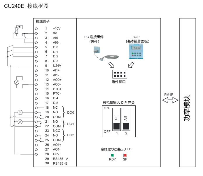
Status indicator: includes a red SF (system fault) indicator light and a green RDY (ready) indicator light.
Core interfaces: analog input interface, power module interface, control terminal, bus termination switch, shielding layer card, option interface (supporting BOP basic operation panel and other options).
(2) Definition of Core Terminals in Wiring Diagram
Terminal Number Function Description Terminal Number Function Description
1 +10V 15 PTC-
2 OV 16 DI4
3 AIO 17 DI5
4 AI0- 18 NC
5 DIO 19 NO(DO0)
6 DI1 20-23 COM, NCC, NO, COM (DO1 related)
7 DI2 24 NO(DO2)
8 DI3 25 COMJ
9 U24V 26 AO1+
10 AI1+ 27 AO1-
11 AI1- 28-29 RS485 -A、UOV
12 AO0+ 30 RS485 -B
13 AO0- – –
14 PTC+ – –
3. Technical parameters of wiring terminals
Design type: Cage spring clamping design, compatible with cable specifications of 0.2~1.5 mm ² (24~14 AWG).
I/O interface configuration: 6 digital inputs (DI), 3 digital outputs (DO), 2 analog inputs (AI), 2 analog outputs (AO), and 1 PTC interface.
Cable requirements: The maximum length of the control cable should not exceed 10 meters (32.8 feet); Unshielded cables can work, but it is recommended to use shielded cables to meet the EMC (electromagnetic compatibility) requirements of CE standards.
4. Bus connection (USS protocol)
Connection method: RS485-UPS bus connection is made through terminals 29 (RS485-A) and 30 (RS485-B).
Transmission rate: The maximum baud rate is 115200 baud.
Terminal switch: The bus terminal switch is located below terminals 29 and 30 and needs to be set according to the bus topology requirements.
5. Installation and disassembly operations
Installation: The control unit is fixed on the power module by card mounting, and the installation and operation of all G120 control units and G120 power modules are completely consistent, without distinguishing models.
Disassembly: Press the release button on the top of the power module to remove the control unit from the power module.
Pre power on inspection (14 mandatory items)
Before powering on, the following checks need to be completed one by one to ensure that the system has no safety hazards and can be started normally:
Check the serial number, check the core requirements of the project
1. The environmental conditions meet the technical requirements of the frequency converter/motor (such as temperature, humidity, dust prevention, etc.)
2. Installation firmness: The frequency converter and motor are installed firmly without looseness
3. The installation and cooling installation methods are correct, and there is sufficient cooling air supply around the equipment
4. There are no safety issues with the readiness status of the motor and application equipment, and the motor can rotate freely (without jamming or obstruction)
The grounding and protection measures of the frequency converter are good, and there are no hidden dangers of poor grounding
6. Matching of power supply voltage: The input power supply voltage meets the rated input voltage requirements of the frequency converter
7 Fuse configuration: The fuse model for the input power supply is selected correctly and installed in place
8. The motor wiring and steering motor wiring are correct, and the steering direction meets expectations when starting
9. The wiring of the motor and power supply is good, and the tightening torque should be tightened according to the technical requirements
10 motor phase sequence: The motor phase sequence is not reversed (incorrect phase sequence may cause serious damage to connected equipment)
11. Cable routing: Separate the motor power cable from other control cables to avoid interference
12. The control signal wiring is correct and meets the corresponding technical requirements
13. There are no tools or foreign objects around the environmental cleaning equipment that may cause damage to the system operation
14. Unique power supply: The frequency converter is the only power supply device for the motor (to avoid multiple power supply conflicts)
Debugging the entire process (taking STARTER software as an example)
1. Debugging core prerequisites
The frequency converter (power module+control unit) cannot be directly applied after arrival and must be debugged before being put into use.
Debugging method: ① Download a set of valid parameters through BOP or STARTER; ② Gradually complete debugging through BOP or STARTER (this guide focuses on the STARTER software debugging method, refer to the control unit operation guide for other methods).
Hardware matching requirements: ① The rated current of the frequency converter shall not be less than the rated current of the motor; ② The output voltage level of the frequency converter matches that of the motor.
2. Debugging preparation work
(1) Equipment and software preparation
Software: Install STARTER debugging software on the PC, which can be obtained from the supply package of PC connection components or downloaded from the latest version through the link.
Hardware: Connect the frequency converter to the PC through the PC connection component (order number: 6SL3255-0AA00-2AA0).
3. Specific debugging steps
(1) Step 1: Create a STARTER project
Power on the frequency converter, start the STARTER debugging software, select “new project”, and follow the project wizard to operate.
Enter an easily recognizable project name (such as “Basic Debugging”), and click “Continue” to add comments.
Set PG/PC interface:
Click on ‘Change and test…’. If the ‘PC COM Port (USS)’ interface already exists in the ‘PG/PC interface’, click on ‘properties’ directly; If it does not exist, click “Select…” and install “PC COM Port (USS)” in “Install/Remove Interfaces”. After successful installation, click “Properties”.
Configure interface parameters: Select COM ports (COM1/COM2/COM3) and baud rate (default 38400), click the “Read” button to confirm the values; If the baud rate test area displays “???”, the serial port needs to be replaced; Select “Automatic mode” under the “RS485” tab and click “OK” to return.
Insert frequency converter: Name the frequency converter (such as “SINAMICS_G120_CU240E”, no spaces or special characters allowed), click “Continue” to enter the summary prompt dialog box, and then click “Complete” to end the project creation.
(2) Step 2: Connect to the frequency converter online
After the project was created, STARTER was in “Offline mode” and did not establish a connection with the inverter.
Click the online connection button to pop up the online/offline data comparison dialog box: the left side shows online frequency converter data, and the right side shows offline project data.
Click on ‘Load HW configuration to PG’ to upload the hardware configuration of the online frequency converter to the PC. Close the dialog box to complete the online connection, and switch the software status from ‘Offline mode’ to ‘Online mode’.
(3) Step 3: Start debugging
After successful online connection, if it is the first time debugging, a fault message F00395 will pop up (indicating that the frequency converter has not been debugged). Select the message and click “Acknowledge” to confirm and start debugging.
Double click the inverter object to enter the debugging wizard, and configure parameters according to the following process:
Control structure configuration: Confirm basic parameters such as control mode (default V/f linear characteristics), driver dataset (DDS 0), command dataset (CDS 0), etc.
Frequency converter function selection: It is recommended to choose “Identification of all parameters including the saturation curve” (automatic recognition of parameters including saturation curve). This function will perform motor data recognition once after the drive is enabled, and the motor may rotate no more than 1/4 turn. When the subsequent drive is enabled, it will optimize the rotation of the motor.
Motor data calculation: It is recommended to select “Restore factory setting and calculate motor data only”, or choose “Calculate motor data only” or “Exit motor commissioning”.
Summary confirmation: The debugging wizard will display the configured driver data (control structure, set values/command source default values, motor data, etc.) at the end. You can click “Copy text to clipboard” to backup, and click “Continue” to proceed to the next step.
Motor parameter recognition startup:
Click on ‘Control panel’, then click on ‘Assume control priority’ (if connected via BOP link RS232, this button will change to ‘Return’).
Click “Enable” to activate the ON/OFF button, and then click the ON button to start motor parameter recognition. During the recognition process, if the relevant buttons are disabled, an alarm 541 “Motor Identification Active” will be displayed.
After recognition is complete, the alarm is cancelled and the button is restored to its active state. Click on “Give up control priority!” and pay attention to the warning message that pops up.
Parameter saving: Open the SINAMICS project, click the “Copy RAM to ROM” button, and save the debugging parameters to the EEPROM of the inverter to avoid parameter loss.
(4) Step 4: Application debugging and disconnection
After basic debugging is completed, application debugging can continue through the STARTER navigation dialog box, or specific functional modules (such as input/output, setpoint channels, closed-loop control, etc.) can be fine tuned directly.
After debugging, click the disconnect button and select the save method in the pop-up save dialog box: ① Save the inverter project to the PC; ② Upload parameter settings to PC; ③ Save the parameters from RAM to EEPROM, and disconnect the PC from the inverter after completion.
4. Factory reset operation
(1) Function Description
All frequency converter parameters can be restored to their factory settings through factory reset. During the reset process, the communication memory will be reinitialized, causing communication interruption between the PC and the frequency converter.
(2) Operation steps
Ensure that the frequency converter is online (if offline, click the “connect to target system” button).
Select the frequency converter that needs to be reset in the STARTER navigation area.
Click on the factory reset icon and follow the prompts to complete the reset operation.
Fault diagnosis system
1. Definition of faults and alarms
(1) Fault
Nature: The device is in a serious abnormal state, which can affect the safe operation of the system.
Handling mechanism: When a fault occurs, the frequency converter automatically stops through the OFF2 command, and the red SF (system fault) LED on the control unit lights up; The frequency converter can only be restarted after confirming the fault.
(2) Alarm
Nature: The equipment is in an extreme state (which may cause malfunctions) or a special temporary state (such as motor parameter identification), and does not affect the basic operation of the system.
Processing mechanism: No manual response is required, the alarm status will be automatically eliminated or continuously prompted as the working conditions change.
2. Common faults and their solutions
Fault code, fault cause, handling measures
F00001 overcurrent, motor power does not match frequency converter power. Check if the rated power of the frequency converter and motor are consistent to ensure matching
F00002 overvoltage, high power supply voltage or motor in power generation state. Check if the input power supply voltage is within the rated range and investigate the cause of the motor’s power generation condition
F00003 undervoltage, power failure or low voltage. Check the stability of the power supply and troubleshoot power outages or voltage drops
F00004 frequency converter overheating, exceeding the upper temperature limit, check whether the motor load is overloaded, whether the carrier pulse frequency is set reasonably, whether the ambient temperature is too high, and install a cooling fan if necessary
F00005 frequency converter overload check whether the motor power matches, whether the load change cycle is reasonable, and optimize the load working conditions
F00041 motor parameter recognition failed. Check if the wiring from the motor to the frequency converter is correct and confirm if the motor nameplate data is accurately inputted
F00052 Power module hardware data read failure. Check if the connection between the control unit (CU) and the power module (PM) is secure and in good contact
F00062 MMC data is invalid. Copy MMC parameters again to ensure a complete and uninterrupted copying process
F00070 PLC setting value fault check parameter P2040 numerical setting to ensure that the setting value is correct and effective
F00071 USS setting value fault. Use STARTER software to check if the USS communication settings (such as baud rate, address, etc.) are correct
F00072 USS setting value fault check whether the communication status and parameter configuration of the USS main station are normal
F00090 Encoder Feedback Signal Loss Check if the encoder is securely installed and wired correctly, and re debug the encoder
After replacing the F0395 CU/PM with power on, copying the startup parameters, or confirming if the device replacement process is standardized due to EEPROM read errors, perform parameter copying or debugging again, and troubleshoot EEPROM faults
3. Common alarms and their meanings
Alarm code alarm meaning
The parameters and configuration settings of A0700 PROFIBUS master station are invalid, and the PROFIBUS configuration needs to be modified
A0702 PROFIBUS connection interrupted, check the connectors, cables, and PROFIBUS master station
A0703 cannot obtain the set value from the PROFIBUS master station (control word=0) or the set value is invalid. Check the output of the master station set value
At least one intermediate node of A0704 configuration is not working or has malfunctioned
A0705 cannot obtain actual value from frequency converter (no frequency converter fault)
A0706 r2041 No diagnostic information, there may be a PROFIBUS DP software malfunction
A0710 frequency converter detected a PROFIBUS communication fault, and the communication port on the control unit may have malfunctioned
A0711 PROFIBUS parameter is invalid, check P0918 address settings and parameter P2041
4. LED status indication diagnosis
The control unit displays the device status through two LED indicator lights, with the following specific meanings:
LED name, color, status, meaning
SF (system malfunction): The red lit device indicates a system malfunction related to software and hardware
SF (system fault) red off, no system fault
SF (system fault) flashing red (0.5Hz) fault not confirmed or fault ongoing
RDY (Ready) green light indicates that the frequency converter is ready to start running (does not mean it is currently running)
RDY (Ready) green goes out. The frequency converter is not ready (such as not powered on, faults not resolved, etc.)
RDY (Ready) green flashing (0.5Hz) device in standby or transition state
Variable speed operation: Pump/fan application can save energy up to 60% -70%
Braking energy feedback: energy-saving for lifting applications up to 60%
Paired with high-efficiency motors: SIMOTICS motors can increase energy efficiency by up to 10%
SINAMICS G130 built-in frequency converter (75kW-800kW)
Basic Parameters
Power supply voltage, power range, rated output current range, protection level
3AC 380-480V 110kW-560kW 210A-985A IP00/IP20
3AC 500-600V 110kW-560kW 175A-810A IP00/IP20
3AC 660-690V 75kW-800kW 85A-810A IP00/IP20
Core components and technical data
Power module (6SL3310 series):
Including 6-pulse rectifier, IGBT inverter, and pre charging circuit
Cooling method: forced air cooling (AF), coated circuit board anti-corrosion
Control unit (CU320-2):
Communication interface: PROFIBUS (CU320-2 DP)/PROFINET (CU320-2 PN)
Expansion interface: Supports DRIVE CLiQ, can be connected to TM31 terminal module and SMC30 encoder module
Auxiliary components:
Component Type Model Example Function
The incoming filter 6SL3000-0BE32-5AA0 reduces EMC interference and meets the requirements of Class C2 environment
Braking module 6SL3300-1AE31-3AA0 25kW braking power, equipped with dynamic resistor
Outlet reactor 6SL3000-2BE32-1AA0 reduces motor voltage stress and supports 300m cable
Features
Control functions: vector control without encoder, V/f control, PID process controller (liquid level/flow control)
Protection functions: motor I ² t overheating protection, ground fault monitoring, electronic short circuit protection
Special features: Kinetic Energy Buffer (KIP), Capture Restart (supported by VSM10 module), Drive Control Chart (DCC)
SINAMICS G150 Variable Frequency Speed Control Cabinet (75kW-2700kW)
Basic parameters and cabinet types
Power and Voltage:
Power supply voltage, single cabinet power, parallel cabinet power
3AC 380-480V 110kW-560kW 630kW-900kW
3AC 500-600V 110kW-560kW 630kW-1000kW
3AC 660-690V 75kW-800kW 1000kW-2700kW
Cabinet type:
A-type cabinet: compatible with all options (main switch, filter, etc.), supports parallel power units
C-type cabinet: no incoming components, compatible with central low-voltage distribution unit (MCC)
Core Options (Key Categories)
Option Category, Option Code, Function Description, Compatible Cabinet
Electrical Option L13 Main Contactor (≤ 800A) Type A
L23 incoming line reactor (uk=2%,>500kW standard) type A/C
Safety Option K01 1 1 Axis Safety License Type A
K88 Safety Brake Adapter (230V AC) Type A
Protection option M54 has been upgraded to IP54 Type A/C protection level
Document Options D91 English/Chinese Language Pack Type A/C
Operation and maintenance
Standard AOP30 panel: 240 × 64 pixel green backlit LCD, supports 6 languages (including Chinese), two-level security lock (keyboard lock+password)
Maintenance features: modular components are easy to replace, dust plugs (6SL3066-4CA00-0AA0) protect DRIVE CLiQ ports, pre installed cables reduce wiring time
Compliance and supporting products
Core Compliance Standards
European directives: Machinery Directive 2006/42/EC, Low Voltage Directive 2014/35/EU, EMC Directive 2014/30/EU
Certification: cULus (North America) CE、RCM、RoHS II、UKCA
matching products
Motor: SIMOTICS series (low-voltage motor, reduction motor, explosion-proof motor, compatible with SINAMICS)
Industrial switch: SIRIUS series (compliant with IEC 60947)
Communication: SIMATIC NET (Industrial Ethernet, PROFINET Switch)
Distribution: SENTRON (low voltage distribution), SIVACON (switchgear)
Key tips for selection and ordering
Key points for G130 selection
Power matching: Select the power module based on the rated power of the motor and the power supply voltage (e.g. 6SL3310-1GE32-1AA3 for 380V 110kW)
Component matching: The incoming reactor needs to be selected based on the RSC value (relative short-circuit capacity), and RSC>corresponding threshold must be configured (such as RSC ≤ 43 for<200kW)
Key points for G150 selection
Cabinet selection: For existing MCC, choose C-type cabinet, and for expansion options, choose A-type cabinet
Parallel cabinet: For power>800kW (690V), a parallel cabinet should be selected (such as 6SL3710-2GH42-7EA3 for 2700kW)
Option combination: Emergency stop options (L45/L57) need to be paired with power disconnect components (L13/L26)
Siemens SINAMICS low-voltage frequency converter is a comprehensive solution for industrial drive scenarios, covering a power range of 0.12kW (micro power) to 6840kW (high power), supporting voltage levels of 1AC 200-240V and 3AC 200-690V, and adapting to most global power grid standards. It can meet diverse needs from basic fan and pump control to high-precision servo positioning.
Core strengths
Digital integration: support connection to the MindSphere cloud platform, achieve predictive maintenance through edge computing and data analysis, and reduce unplanned downtime;
Efficient Engineering: Provides a full process tool from selection (DT Configurator), programming (TIA Portal/Startdrive) to debugging (Smart Access Module), simplifying the integration of drive systems;
Safety Integrated: Built in safety functions such as STO and SS1, in compliance with IEC standards, without the need for additional electromechanical components, reducing costs;
Collaborative compatibility: Seamless collaboration with SIMOTICS motors, SIMATIC controllers, and SIMOGEAR gear motors, achieving high-speed communication through PROFINET.
Product classification and key parameters
1. Standard performance frequency converter (basic universal scenario)
Model, Power Range, Voltage Level, Protection Level, Core Functions, Applicable Scenarios
SINAMICS V20 0.12-3kW(1AC); 0.37-30kW(3AC) 1AC 200-240V; 3AC 380-480V IP20 V/f control USS/Modbus RTU、 Basic pumps/fans without safety functions, simple machinery
SINAMICS G130/G150 G130:75-800kW; G150:75-2700kW 3AC 380-690V G130:IP00/IP20; G150: IP20 (optional IP54) high power, 100% motor voltage, optional harmonic filter extruder, mixer, large pump/fan
2. Industry specific frequency converter (customized scenario)
Model, Power Range, Voltage Level, Core Characteristics, Applicable Scenarios
SINAMICS G120X 0.75-560kW(3AC 380-480V); 3-630kW (3AC 500-690V) 3AC 200-690V infrastructure specific, -20 ℃ low-temperature start-up, BACnet communication water/water treatment, building air conditioning fan
SINAMICS G180 2.2-6600kW 3AC 380-690V ATEX certified, explosion-proof motor adaptation, optional liquid cooling (IP54) for pumps/fans and compressors in hazardous areas (such as chemical industry)
3. High performance frequency converter (high dynamic/high-power scenarios)
Model, Power Range, Drive Type, Core Functions, Applicable Scenarios
SINAMICS G120D 0.75-7.5kW Distributed Installation IP65 Energy Recovery, Multi Safety Function (STO/SS1) Distributed Production Equipment, Storage AGV
5. Servo type frequency converter (for high-precision positioning scenarios)
Model Power Range Control Mode Core Features Applicable Scenarios
SINAMICS V90 0.05-7kW servo control (with encoder) One Button Auto Tuning, simple positioning of pulse/direction interface (such as packaging machine, small machine tool)
SINAMICS A10 0.05-7kW servo control OCC single cable connection, fully integrated TIA, web server debugging high-precision assembly line, electronic equipment processing
SINAMICS 0.12M 0.25-1.1kW (distributed); 75-5700kW (chassis) DC/AC multi axis system, IP65 protection, PROFIenergy large robot workstation, complex production line
Digitization and Engineering Tools
Selection and Configuration Tools
DT Configurator: Quickly select the full drive chain from motor, frequency converter to controller, automatically generate technical parameters and order information;
SIZER for Siemens Drives: Calculate load, energy consumption, and performance based on application requirements, and output installation drawings and characteristic curves;
SinaSave: A web tool that evaluates energy-saving potential and provides financial analysis and investment return cycles.
Programming and Debugging Tools
TIA Portal (Integrated SINAMICS Startdrive): a unified programming environment that enables seamless integration of frequency converters and SIMATIC controllers;
SCOUT: Advanced programming for high-performance drivers such as S120/C150, supporting multi axis motion control;
Smart Access Module: Simplify on-site operations through remote debugging via mobile devices (phones/tablets).
digital connection
Cloud platform: Connect MindSphere through MindConnect to achieve device status monitoring, fault warning, and remote maintenance;
Edge computing: local analysis of driving data, no delay response exception (such as overload, temperature exception);
Communication protocol: Supports PROFINET (IRT real-time) PROFIBUS DP、EtherNet/IP、Modbus TCP/RTU, Adapt to different automation systems.
Security features and collaborative compatibility
Safety Integrated: All SINAMICS frequency converters have built-in or optional safety functions that comply with the IEC 61800-5-2 standard. The core functions include:
STO (Safe Torque Off): Cut off the motor torque to prevent accidental starting;
SS1 (Safety Stop 1): Stop the machine according to the preset deceleration curve;
SLS (Safety Speed Limit): Limit the maximum speed of the motor to protect personnel and equipment;
Advantages: No need for external safety relays, reducing wiring and component costs, and shortening debugging time.
Equipment collaboration
Motor adaptation: Perfectly compatible with the full range of SIMOTICS motors (GP standard asynchronous, SD synchronous reluctance, XP explosion-proof, DP smoke exhaust motor, etc.);
Controller collaboration: seamless communication with SIMATIC S7-1200/1500, SINUMERIK CNC system, and SIMOTION motion controller to achieve integration of motion control and logic control;
Gear and coupling: adapted to SIMOGEAR gear motor, forming a complete drive unit of “frequency converter motor gear”.
Product positioning and applicable scenarios Siemens Climatix ™ The S400 STD HVAC Controller (POS646 series) is a programmable modular controller designed specifically for residential and light commercial buildings. Its core is used for HVAC system control, including heat pumps, boilers, hybrid systems, cascade systems, heat exchange units (HIUs), and district heating (DHC) scenarios, supporting flexible customization for OEM customers.
Core models and physical characteristics
Model Type Installation Method Weight Protection Level Minimum Order Quantity (MOQ) Inventory Number (SSN)
POS466.05/100 PCB type screw installation 275g IP00 20 units S55384-C660-F100
POS466.65/100 HSG type (with housing) DIN rail/screw installation 427g IP20, 20 units S55384-C666-F100
POS466.65/101 HSG type (with housing) DIN rail/screw installation 479g IP20 1 S55384-C666-F101
Note: The logistics center is located in Nuremberg, Germany (DCN), and ordering requires providing the model number (ASN), inventory number (SSN), and quantity.
Compliance and reliability
Compliance certification: Compliant with EN 60730-1 standard, with EU CE (A5W00713702A), UKCA (A5W00713706A), RCM (A5W00713708A) certification, and environmental compatibility documents can be found in A5W00709166A (RoHS compliance, material composition, etc.).
Reliability: MTBF (mean time between failures)>65 years (calculated based on SN29500 standard at 20 ℃ environment), meeting the long-term stable operation requirements.
Hardware configuration and interface
1. Power parameters
Main power supply (T02 terminal): AC 230V (+10%/-15%), 50/60Hz, requires external overcurrent protection (slow melting fuse ≤ 10A or B/C/D type circuit breaker).
Power consumption: Minimum power consumption (controller only) 4.5W ± 0.2W (25 ℃), maximum power consumption 130VA (full load including secondary power supply).
Secondary power supply (providing power to peripherals with maximum current limit):
Secondary power supply voltage range maximum current note
5V(T28) DC 5V±2.5% 40mA –
12V(T28/T42) DC 12V±2.5% T28:40mA; T42:50mA –
24V (T24/T44/T50) DC 24V ± 10% 522mA (shared) maximum 3.5mF capacitive load
24V (T70, for expansion module) DC 24V ± 10% 1080mA maximum 3.5mF capacitive load
2. Core interface resources
I/O interface (18 multifunctional channels): Supports analog signals (NTC 1k/10k, Pt1000, LG-Ni1000, 0-10V DC, 0/4-20mA DC), digital signals (AC 230V/DC 24V), pulse counting (≤ 150Hz), frequency input (≤ 500Hz), PWM input/output (500Hz-2.5kHz), as specified in the terminal table (e.g. T28/T30/T34 for input, T24 for output).
Communication interfaces (9 types):
Interface Type Terminal Core Parameters Typical Applications
LINbus T42 19.2kbps, Non isolated, up to 2 LINbus devices such as pumps/fans can be connected
RS485 (non isolated) T44 Modbus RTU/BACnet MS/TP, up to 15 server room units (such as POL824), BMS integration
RS485 (isolated) T46 Modbus RTU, up to 15 server heat pump outdoor units, BMS equipment integration
Ethernet IP T56/T58 10/100Mbps, Support BACnet IP/Modbus TCP/IP cloud connection (Climatix IC) and BMS integration
USB-C T54 USB 2.0 OTG, USB-A to C adapter is required to connect WLAN stick (debugging) and USB storage (file transfer)
Expansion Interface (T70): Peripheral bus, supporting the connection of Climatix I/O expansion modules (such as POL966, POL95E) and communication expansion modules (such as POL935 OpenTherm, POL937 M-Bus), up to 3 I/O expansion modules+10 communication expansion modules (POL935).
The green constant light application has been loaded and is running normally
The yellow constant light application has been loaded but not running
Yellow flashing (50ms on/1000ms off) Application not loaded
Red flashing (2Hz) firmware error
Hardware malfunction with constant red light
Software and tool support
programming tools
Climatix Project Studio Automation/APRO: Used for HVAC application programming, providing Level 3 support:
Level 1: OEM independent programming (including heating, ventilation, and cooling application libraries and templates);
Level 2: APC (Application Programming Center) or local partners provide programming services;
Level 3: Siemens pre developed configurable applications (such as fresh air heat recovery HRV, district heating HCS/DHC).
Configuration and Debugging Tools
Climatix SCOPE: OEM used for HVAC unit configuration, with the ability to modify watch pages, text, language, access permissions, and trend records.
Climatix SCOPE Light: Simplified version for OEM laboratory testing.
Climatix smartHMI APP/API: Install and debug tools, connect controllers through mobile devices, and support commissioning.
Climatix DEVICE REST API: Factory integration interface used to access controller data.
Cloud Services and Remote Access
Climatix IC Cloud: Provides remote access and cloud services (such as data monitoring and remote control), with cloud service model POL0L2.01/STD (SSN: P55693-L121-A100), and communicates via Ethernet IP.
Communication Extension (OpenTherm) POL935.10/STN PCB Type, OpenTherm Communication A6V14064329
Communication Expansion (M-Bus) POL937.00/STN HSG Type, M-Bus Communication A6V14669764
Note: The expansion module needs to be connected to a Board to Board connector (POL001.45/STD) or a Board to Connector (POL002.43/STD). If the power supply to the controller is insufficient, an external 24V power supply (such as POL0B5.55/STD, 75W) is required.
2. Key attachments
Room units and sensors:
Type, Model, Description, Communication Method
Touch room unit POL824.40/STD is used for user operation of Modbus
Outdoor temperature sensor QAC34 NTC 1k-
Immersion temperature sensor QAE16 PT100/1000-
HMI devices:
Type, Model, Description, Communication Method
Text HMI (TM) POL871. RJ45 interface HMI Bus Modbus FT1.2
Touch HMI (7 inches) POL8T2.70/STD RJ45/Ethernet HMI Bus Modbus FT1.2
Other attachments:
WLAN stick: POL903.00/100 (USB-A interface, requires conversion to C adapter, used for smartHMI connection);
External power supply: POL0B5.55/STD (24V DC/75W, supplying power to the expansion module);
Terminal connectors: Phoenix/Dinkle brand, such as POL001.45/STD (board to board), POL002.43/STD (board to wire), need to be ordered separately (MOQ 100 pieces).
Installation and safety regulations
Installation requirements
Space requirements: A gap should be reserved around the controller (Ethernet/USB-C end ≥ 30mm, I/O expansion module end ≥ 40mm);
Fixing method: fix with M3.5 metal screws (head diameter ≤ 8mm, not included in the supply);
Cable requirements: Different interface cables have a maximum length limit (such as Ethernet ≤ 100m, RS485 ≤ 1000m, LINbus ≤ 3m), and shielding is required for cables exceeding 3m.
Safety Warning
No internal fuses: All AC 230V circuits require external overcurrent protection (≤ 10A), with a total current not exceeding 10A;
Anti electric shock: AC 230V and SELV (Safety Extra Low Voltage) cables need to be double insulated, and the power supply should be disconnected before plugging or unplugging the terminals;
Anti static: When touching the PCB board, wear an anti-static wristband and and clothing to avoid direct contact with the components.
Maintenance and Disposal
Maintenance: The controller is designed to be maintenance free and does not require regular maintenance;
Disposal: Products and packaging cannot be used as household waste and must be classified and recycled according to local regulations. All personal data must be deleted before recycling.