HIRSCHMANN MACH1040 Series
Product Overview
(1) Core positioning and design philosophy
A fully gigabit reinforced switch designed specifically for industrial automation scenarios, meeting the high reliability, long-term stability, and flexible configuration requirements in extreme industrial environments. Following the IEEE 802.3 standard, supporting the construction of switched industrial Ethernet networks, fanless design reduces the risk of mechanical failures, and adapts to harsh working conditions such as vibration, wide temperature range, and electromagnetic interference.
(2) Model variants and core differences
The series includes four basic models, which combine different characteristics (port position, PoE function, temperature range, power supply type, etc.) through product names. The specific differences are as follows:
Model Port Position PoE Support Core Configuration Special Design
MAR1040 front-end does not have 16 gigabit combination ports, optional redundant power supply basic model, suitable for conventional industrial scenarios
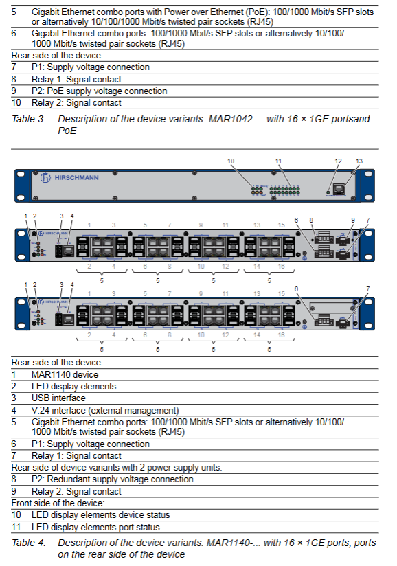
The MAR1042 front-end has 16 Gigabit Ethernet ports (4 PoE ports) and dual power supply units (including PoE power supply) that support PoE terminal power supply for IP phones, cameras, and other devices
MAR1140 does not have 16 gigabit combination ports in the backend, but has an additional Fast Ethernet diagnostic port in the frontend. Optional redundant power supply ports can be installed in the rear for easy wiring management, and the diagnostic port simplifies maintenance
MAR1142 has 16 Gigabit Ethernet ports (4 PoE ports) in the backend (IEEE 802.3af), an additional Fast Ethernet diagnostic port in the frontend, and dual power supply units that combine port placement and PoE functionality, making it suitable for complex installation scenarios
(3) Core functional characteristics
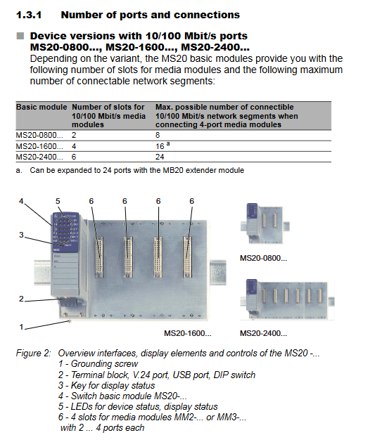
Port configuration: 16 Gigabit combo ports, each port can be connected to either twisted pair (RJ45 socket, supporting 10/100/1000 Mbit/s) or optical module (SFP slot, supporting 100/1000 Mbit/s). After inserting the SFP optical module, the corresponding RJ45 port will be automatically disabled.
PoE function: Only supported by MAR1042 and MAR1142, compliant with IEEE 802.3af standard. The four PoE ports are the first four ports of the device (Port 1-4), with a maximum output power of 15.4W per port. It provides phantom power through signal twisted pair cable
Technical parameter details
(1) Physical and weight parameters
Project specifications
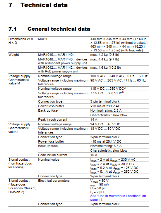
Dimensions (W × H × D) without bracket: 448mm × 345mm × 44mm (17.64in × 13.58in × 1.73in); With bracket: 463mm × 345mm × 44mm (18.23in × 13.58in × 1.73in)
Weight MAR1040/MAR1140: maximum 4.2kg (9.3lb); Equipped with redundant power supply: maximum 4.4kg (9.7lb); MAR1042/MAR1142 (PoE): Maximum 4.6kg (10.2lb)
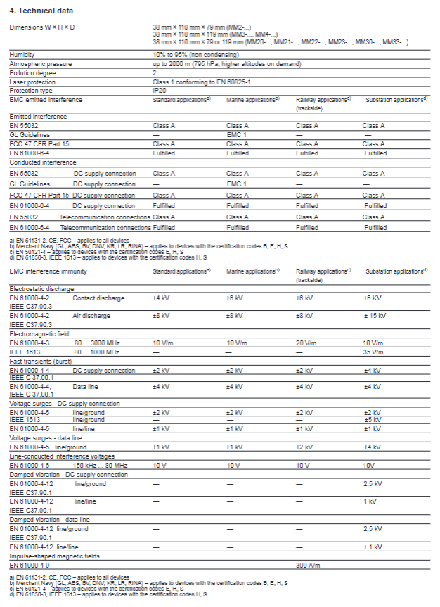
Protection level IP30
Laser/LED protection Class 1 (compliant with IEC 60825-1:2014)
(2) Power supply and electrical parameters
Power supply type, rated voltage range, tolerance range, backup fuse, peak surge current, power-off holding time
L-type (DC) 24-48VDC 18-60VDC 6.3A, slow melting 15A>10ms (20.4VDC)
M-type (AC) 100-240VAC, 50/60Hz 90-265VAC, 47-63Hz 2.5A, slow melting 14A>20ms (230VAC)
M-type (DC) 110-250VDC 77-300VDC 2.5A, slow melting 14A-
Signal contact (non hazardous environment) Umax 230VAC/30VDC, Imax 2A; Umax 125VDC,Imax 0.2A; Umax 250VDC,Imax 0.1A
Signal contact (hazardous environment) Vmax 30V, Imax 90mA, Ci 50pF, Li 2 μ H
(3) Network performance parameters
Port type, speed support, transmission standard, maximum transmission distance
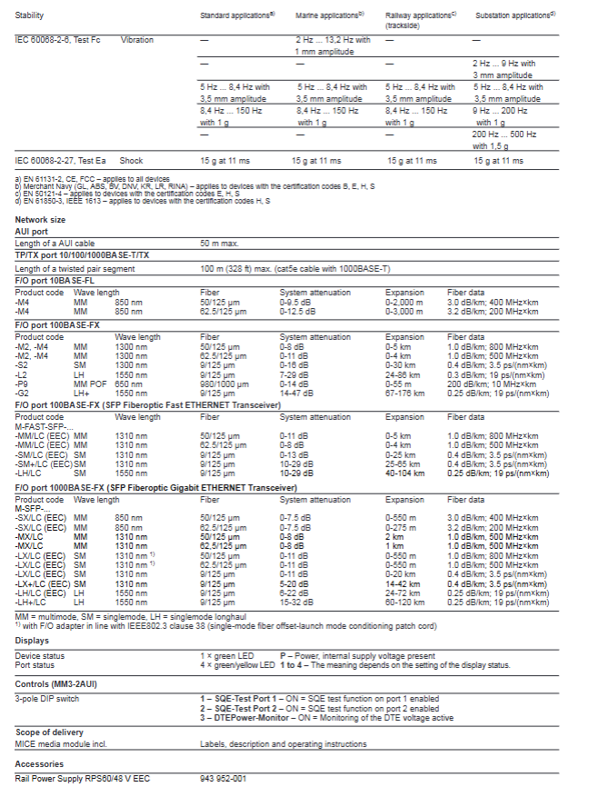
Twisted pair port (RJ45) 10/100/1000 Mbit/s IEEE 802.3 10BASE-T/100BASE-TX/1000BASE-T 100m (Cat5e cable)
Optical port (SFP, 100M) 100 Mbit/s IEEE 802.3 100BASE-FX multimode (50/125 μ m): 5km; Single mode: 25km; Long distance (LH): 140km
Optical port (SFP, 1000M) 1000 Mbit/s IEEE 802.3 1000BASE-SX/LX/LH multimode (50/125 μ m): 0.55km (SX)/1.5km (MX); Single mode: 20km (LX)/128km (LH+)
(4) Electromagnetic compatibility (EMC) parameters
Test Project Standard Test Level
Electrostatic discharge IEC/EN 61000-4-2 Contact discharge ± 8kV, air discharge ± 15kV
Electromagnetic radiation immunity IEC/EN 61000-4-3 80MHz-2700MHz, 20V/m
Fast transient pulse group IEC/EN 61000-4-4 power/data line ± 4kV
Voltage surge IEC/EN 61000-4-5 power line ± 2kV (line to ground)/± 1kV (line to line) (AC); ± 4kV (line to ground)/± 2kV (line to line) (DC)
Conducted interference IEC/EN 61000-4-6 150kHz-80MHz, ± 4kV (line ground), 10V
Radiation emission EN 55032/FCC 47 CFR Part 15 Class A
Maintenance, disassembly, and troubleshooting
(1) Key points of daily maintenance
Regular inspection:
Environmental inspection: Confirm that the installation environment temperature and humidity meet the requirements, and there is no dust accumulation.
Equipment inspection: The ventilation duct is unobstructed, the LED indicator light is normal, and the casing has no damage or signs of overheating.
Cable inspection: The cable connection is firm, without wear or aging, and the stress relief device is effective.
Relay inspection: Regularly check the contact resistance of the relay according to the switching frequency to ensure that the switch function is normal.
Software maintenance: Regularly visit the Hirschmann official website to check for software updates, upgrade in a timely manner to obtain new features and troubleshooting.
Cleaning requirements: Only use a dry soft cloth to clean the equipment casing, and do not use liquid cleaning agents or corrosive substances.
(2) Dismantling process
Equipment disassembly:
Disconnect all data cables (twisted pair, fiber optic).
Turn off the power supply and disconnect the power cable.
Disconnect the grounding cable.
Remove the fixing screws of the equipment (cabinet/wall) and take out the equipment.
SFP optical module disassembly:
Open the locking mechanism of the SFP optical module.
Pull the locking mechanism and remove the optical module from the slot.
Cover the optical module with a protective cap and store it properly.
Precautions: During the disassembly process, avoid colliding or squeezing the equipment to protect the interface and terminals from damage; Dismantling in hazardous environments requires ensuring that the area is free of flammable gases.
(3) Guidelines for Handling Common Malfunctions
Possible causes and solutions for the fault phenomenon
The power supply light (P) does not light up. The power supply voltage does not match, the wiring is incorrect, and the fuse is blown. Check the power supply voltage and wiring for correctness, and replace the blown fuse
The fault light (FAULT) is on. Check the system logs for device faults, IP conflicts, and abnormal port connections to determine if there are any IP conflicts. Check the port cable connections. If there is a device fault, return it for testing
Port not connected (LED not lit), cable failure, opposite device not powered on, port disabled, cable replacement. Confirm that the power supply to the opposite device is normal, and enable the port through the management tool
Abnormal data transmission (LED flashing), failed rate negotiation, electromagnetic interference, incompatible optical module, manually set port rate and duplex mode, check cable shielding and wiring distance, replace compatible SFP optical module
PoE terminal cannot supply power. PoE port is not enabled, terminal power consumption exceeds the standard, and cable fault occurs. Enable PoE port, confirm that terminal power consumption is ≤ 15.4W, and replace with qualified twisted pair cable
Accessories
Recommended accessories and order number
Accessory category, specific model, order number, and purpose
Fast Ethernet SFP optical module M-FAST SFP-MM/LC 943 865-001 multimode fiber connection (100M)
Fast Ethernet SFP optical module M-FAST SFP-SM/LC 943 866-001 single-mode fiber connection (100M)
Gigabit Ethernet SFP optical module M-SFP-SX/LC 943 014-001 multimode fiber connection (1000M, short distance)
Gigabit Ethernet SFP optical module M-SFP-LX/LC 943 049-001 single-mode fiber connection (1000M, long distance)
Automatic configuration adapter ACA22-USB (EEC) 942 124-001 configuration backup/loading, software upgrade
Terminal Cable Terminal Cable 943 301-001 V.24 Interface Connection
Fixed bracket additional fixed bracket 943 943-001 Strong vibration environment reinforcement
Protective cap RJ45 socket protective cap (50 pieces) 943 936-001 unused port protection
Protective cap SFP slot protective cap (25 pieces) 943 942-001 Unused SFP slot protection
Compliance certification and environmental requirements
(1) Compliance certification
EU certification: CE marking, compliant with the 2011/65/EU (RoHS), 2014/30/EU (EMC), 2014/35/EU (Electrical Equipment Safety) directives.
UK certification: UKCA marking, compliant with S.I. 2012 No. 3032 (RoHS) and S.I. 2016 No. 1091 (EMC) regulations.
US certification: FCC Part 15 Class A, UL 508.
Industry certifications: ISA 12.12.01 (Class I Div.2), GL (Lloyd’s Register), IEC 61850, IEEE 1613 (substations), EN 50121-4 (rail transit, trackside), NEMA TS2, EN 50155 (rail transit, on-board).
(2) Environmental Protection and Recycling Requirements
The equipment belongs to electronic waste and must be properly recycled according to the current disposal regulations of the country/state/region after use. It is prohibited to dispose of it indiscriminately to reduce environmental impact.
s and supports remote power supply for PoE terminals such as IP phones, cameras, and sensors.
Redundancy mechanism: Supports ring network redundancy (HIPER Ring), which can quickly reconstruct the network after a failure; Non PoE models can choose redundant power supply, while PoE models come standard with dual power supply units to enhance power supply reliability.
Management interface: Provides multi-dimensional management methods – local management (V.24 interface, RJ11 socket; USB interface, supporting ACA22 automatic configuration adapter), remote management (web browser, Telnet, HiView configuration software, Industrial HiVision network management software).
Display and diagnosis: Real time display of device status (power supply, fault, ring network, standby) and port status (connection, data transmission, disabled) through LED indicator lights; The MAR1140/1142 front-end is equipped with diagnostic ports for easy on-site troubleshooting.
Safety regulations and installation environment requirements
(1) Personnel qualification requirements
Only “qualified personnel” are allowed to operate the equipment. Qualified personnel must meet the following requirements: have received professional training, possess knowledge of safety technical standards related to circuit grounding and identification; Understand potential hazards in the workplace; Master risk prevention measures; Regularly receive retraining.
(2) Mandatory requirements for installation environment
Installation location: It can only be installed in switch cabinets or restricted access areas, and is exclusively accessible to maintenance personnel; Prohibited for use as a desktop device.
Installation method adaptation:
19 inch cabinet installation: sliding/mounting rails are required to support the weight of the equipment and ensure easy cable access; At least one rack space (about 5cm) should be reserved above and below the device for heat dissipation.
Vertical installation on the wall: It must be installed inside a fire-resistant enclosure that complies with IEC/EN 62368-1 standards to avoid the risk of fire.
Environmental parameter threshold:
Temperature: Standard (S) 0 ° C~+60 ° C (+32 ° F~+140 ° F); Expansion type (T/E) -40 ° C~+70 ° C (-40 ° F~+158 ° F), with additional conformal coating for E-type; Storage temperature -40 ° C~+85 ° C.
Humidity: 5%~95% (non condensing state).
Air pressure: up to 2000 meters (795 hPa), higher altitudes require prior consultation.
Pollution level: not exceeding level 2.
Special requirements for hazardous environments (Class 1, Division 2):
Only use models labeled “FOR USE IN CLASS I, DIVISION 2 HAZARDOUS LOCATION”.
When using the USB port, it is necessary to install a tool to lock the casing to prevent accidental operation.
It is prohibited to disassemble or replace equipment when it is in a charged state, unless it is confirmed that there is no concentration of flammable gases in the area.
Do not replace any components as it may affect explosion-proof compatibility.
Signal contacts must comply with electrical parameters (Vmax 30V, Imax 90mA, Ci 50pF, Li 2 μ H), cable length must be calculated based on capacitance/inductance parameters (default 60pF/ft, 0.2uH/ft), and wiring must follow NEC NFPA 70 Article 501 standard.
(3) Electrical safety regulations
Power supply safety:
The power supply voltage must be consistent with the equipment nameplate, L-type (24-48VDC), M-type (100-240VAC/110-250VDC), with a voltage range including maximum tolerance (L-type 18-60VDC, M-type 90-265VAC/77-300VDC).
The power cord needs to use copper wire with a cross-sectional area of not less than 1mm ² (North American AWG16); The cross-sectional area of the protective conductor shall not be less than the power supply wire and shall not be less than 1.0mm ² (AWG16).
The power supply should be equipped with easily accessible disconnect devices (such as switches, plugs) and clearly labeled; The outer conductor of AC power supply or the positive conductor of DC power supply should be equipped with fuses (L-type 6.3A slow melting, M-type 2.5A slow melting), and double fuses are required when the neutral/negative wire is not grounded.
Grounding requirements:
The device is grounded through an independent grounding screw on the back, and the grounding operation must take priority over other cable connections; The grounding cable needs to be operated last when disconnecting.
The shielded grounding wire of the twisted pair cable should be connected to the front panel of the equipment, and the risk of short circuit should be avoided during connection.
Cable and connection safety:
The cable needs to be designed for stress relief to avoid twisting, poor contact, or interruption caused by mechanical stress; Follow the requirements of sections 522.6, 522.7, and 522.13 of DIN VDE 0100-520:2013-06 standard.
At least 10cm of space should be reserved in front of the equipment ventilation duct to ensure heat dissipation; Do not insert sharp objects into equipment or wiring terminals, and do not touch live terminals.
When the device is running or just turned off, the casing may be hot. Do not touch it to avoid burns.
Complete installation process
(1) Preparation before installation
Packaging content inspection: Confirm that it includes 1 device, 2 pre installed brackets and fixing screws, 1-2 3-core power supply terminal blocks (according to model), 1-2 2-core signal contact terminal blocks (according to model), and 1 safety and general information sheet; Check all components for any transportation damage.
Tools and accessories preparation: Prepare suitable screwdrivers, torque wrenches (power terminal 0.51Nm, signal contact terminal 0.34Nm), cables that meet specifications (power line, ground wire, data line), and optional HIRSCHMANN compatible SFP optical modules.
Installation location confirmation: Ensure that the installation location meets environmental parameters, space requirements, and power supply conditions match the equipment.
(2) Core installation steps
1. Optional steps: Install SFP optical module
Remove the SFP optical module from the shipping packaging and remove the protective cap.
Close the optical module latch and insert it into the device SFP slot until the latch locks in place.
Note: Only use compatible SFP optical modules specified by HIRSCHMANN. Please refer to the “Accessories” section for specific models.
2. Power supply and signal contact wiring
Terminal block disassembly: First, remove the power terminal block and signal contact terminal block from the equipment for easy wiring.
Power supply wiring: Connect according to the terminal definition (Pin1: protective conductor, Pin2: DC negative/AC neutral wire, Pin3: DC positive/AC phase wire), ensuring that the wiring is firm and the torque meets the requirements.
Signal contact wiring: Use 0.5-3.0mm ² (AWG20-AWG12) copper wire with a stripped length of 12mm; ensure that the cable is free of voltage, connect and tighten the terminal block with the required torque.
Terminal block installation: Reinstall the connected terminal block back into the device.
3. Equipment fixation and grounding
Cabinet installation: Install sliding/mounting rails in a 19 inch cabinet according to the manufacturer’s requirements, and secure the equipment to the rails with screws through side pre installed brackets; Additional back support brackets (accessories) can be installed in strong vibration environments.
Wall installation: Adjust the pre installed bracket position of the equipment, install additional back brackets (accessories), and fix the bracket to the wall with screws to ensure that the equipment is vertical and stable.
Grounding operation: Connect the grounding screw on the back of the equipment to the protective conductor with a grounding wire. The cross-section of the grounding wire meets the requirements and the connection is firm.
4. Data cable connection
Twisted pair connection: Use Cat5e and above specification cables with a maximum length of 100m; shielded cables (such as SF/UTP, in compliance with ISO/IEC 11801) are required for strong interference environments; Maintain sufficient distance from power cables, avoid parallel laying, and try to form a 90 ° angle when crossing to reduce interference.
Fiber optic connection: Ensure that the SFP optical module model matches the fiber optic type (SX/LX/LH, etc.), and interconnect ports of the same type (such as SX-SX); Pay attention to cleaning the fiber end face during connection to avoid contamination.
5. Equipment power on and status check
After confirming that all wiring is correct, secure, and there is no risk of short circuit, connect the power supply.
Observe the LED indicator light: The device status light shows that the power supply is normal (P light green light is on), and there is no fault (FAULT light is not on); After the port is connected, the corresponding port LED lights up green, and the yellow light flashes during data transmission, confirming that the installation is normal.
(3) Verification after installation
Check if the device’s heat dissipation is normal, without any abnormal heating or noise.
Confirm the port connection status through LED or management tools and test whether data transmission is smooth.
After installation in hazardous environments, it is necessary to confirm that the explosion-proof configuration meets the requirements and there are no safety hazards.
Initial configuration and management operations
(1) Initial login and password modification
Configuration method selection:
Local configuration: Connect to a PC or VT100 terminal through the V.24 interface, with terminal parameters set to 9600 baud rate, 8-bit data bits, 1-bit stop bit, no checksum, and no handshake.
Remote configuration: Connect the device through a web browser, Telnet, or HiView software (default IP address obtained through DHCP).
First login: Use the default account login – administrator account (admin/private, read-write permission), regular user account (user/public, read-only permission).
Password modification: After the first login, the device requires the administrator password to be changed. The new password must include uppercase and lowercase letters, numbers, special characters, and be at least 8 characters long; After modification, log in again for verification.
Password retrieval: If you forget your password, you need to reset it through System Monitor. Please refer to the official website’s knowledge base for specific procedures.
(2) Core default parameters and configuration points
Suggestions for configuring default settings for parameter categories
IP address automatically obtained through DHCP in industrial scenarios. It is recommended to set a static IP address to avoid IP conflicts
Port mode automatic negotiation is enabled, supporting automatic polarity, automatic crossover, and terminal device matching without manual adjustment; In special scenarios, automatic negotiation can be turned off, and the speed and duplex mode can be manually set
The PoE function supports IEEE 802.3af, and the first 4 ports are PoE ports that can be enabled/disabled according to terminal requirements to avoid ineffective power supply
Disabling ring network redundancy requires enabling HIPER Ring functionality, configuring control ports and coupling ports for ring network topology
Signal contacts do not evaluate port link status and configure signal contact triggering conditions as needed (such as power failure, port disconnection, temperature exceeding limits, etc.)
The optical port speed is 100M, and the optical module defaults to full duplex. The gigabit optical module defaults to full duplex and has the same speed as the peer device to avoid negotiation failure
(3) Application scenarios of management functions
Basic configuration: Set IP address, subnet mask, gateway, VLAN, port rate and other basic parameters through web or HiView software.
Batch configuration: Use ACA22 adapter with USB interface to automatically configure adapter, backup/load device configuration, and achieve batch deployment of multiple devices.
Network monitoring: Real time monitoring of device status, port traffic, and ring network status through Industrial HiVision software, setting alarm thresholds.
Troubleshooting: Connect to the terminal through the V.24 interface or diagnostic port, view system logs, and locate power supply, connection, or configuration faults.