Compact design: The component size is compact, saving control room space and can be installed in IEC Zone2/Class I Div.2 hazardous areas, reducing installation costs
Dual redundancy and high reliability: No single point of failure, processors, power supplies, I/O modules, and communication buses all support redundancy, achieving 99.99999% availability through Pair and Spare technology
Online maintenance: Control applications, logic, and parameters can be modified without downtime to meet factory expansion or renovation needs
Open architecture: Supports third-party Ethernet cables, switches, and other devices, with Vnet/IP bus ensuring communication certainty
Flexible combination of functional blocks: covering multiple types of functional blocks such as regulation, sequence, calculation, etc., supporting flexible design from small to large systems
Multi bus and subsystem integration: supports digital fieldbuses such as FOUNDATION fieldbus and PROFIBUS-DP, and is compatible with communication between devices such as PLC and frequency converter
2. FCS model classification (8 core models)
Model Abbreviation Product Name FCU Model Core Software Package
FFCS-V Vnet/IP and FIO specific FCS AFV30 (rack mounted), AFV40 (cabinet mounted) LFS1700 control function package, LFS1750 node expansion package
FFCS-L Vnet/IP and FIO specific FCS AFV10 (rack mounted) LFS1500 control function package, LFS1550 node expansion package
FFCS FIO Compact FCS AFF50 (Rack mounted) LFS1350 Compact Control Function Package
KFCS FIO standard FCS AFS30 (rack mounted), AFS40 (cabinet mounted) LFS1300 standard control function package
KFCS2 FIO Enhanced FCS AFG30 (rack mounted), AFG40 (cabinet mounted) LFS1330 Enhanced Control Function Package
LFCS RIO standard FCS AFS10 (rack mounted), AFS20 (cabinet mounted) LFS1100 standard control function package
LFCS2 RIO Enhanced FCS AFG10 (rack mounted), AFG20 (cabinet mounted) LFS1130 Enhanced Control Function Package
PFCS/SFCS RIO Standard/Compact FCS PFC – S/E/H (Rack mounted) LFS1000/LFS1020/LFS1120 Control Function Package
Note: represents “S” (single redundancy) or “D” (double redundancy)
Detailed explanation of hardware composition
1. Core components
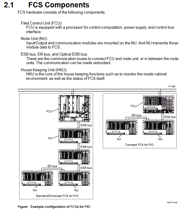
FCU (Field Control Unit): Core computing unit, including processor module, power module, and bus interface module. The dual redundant configuration requires the installation of 2 sets of processors, power supply, and bus interface components
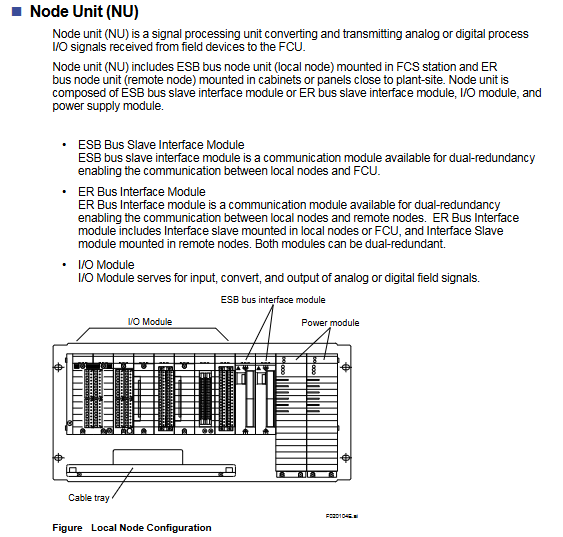
NU (Node Unit): Signal processing unit, including ESB/ER bus interface module, I/O module, power module, divided into local nodes (ESB bus) and remote nodes (ER bus)
Communication bus:
ESB bus: connects FCU with local nodes, supports dual redundancy, and has a maximum transmission distance of 10m
ER bus: connects local and remote nodes, supports dual redundancy, uses Ethernet compatible coaxial cables, and can expand distance through optical relays
Optical ESB bus: only compatible with FFCS-V, supports chain/star topology, with a maximum transmission distance of 50km
HKU (House Keeping Unit): monitors the cabinet environment (temperature, fan status) and FCS’s own status, including HKU main unit, PDU (power distribution unit), fan power supply unit, etc
2. Classification of I/O modules (FIO/RIO specific)
Module type represents model, core specifications
Analog I/O module AAI141 (4-20mA input) 16 channels, non isolated; Supports HART communication version (AAI141-H)
Analog I/O module AAI543 (4-20mA output) 16 channels, isolated; Supports HART communication version (AAI543-H)
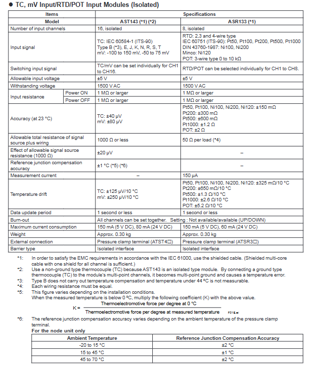
Temperature input module AAT141 (TC/mV) 16 channels, isolated; Supports 8 types of thermocouples
Temperature input module AAR181 (RTD) 12 channels, isolated; Suitable for RTD types such as Pt100
Digital I/O module ADV151 (24V DC input) 32 channels, isolated; Support pressure clamp terminals
Digital I/O module ADV551 (24V DC output) 32 channels, isolated; Support dual redundancy configuration
Communication module ALF111 (FF-H1) with 4 ports, supporting FOUNDATION fieldbus
Communication module ALP111 (PROFIBUS-DPV1) 1 port, compatible with PROFIBUS device communication
Turbomachinery module AGS813 (servo module) isolation design, suitable for turbo machinery control
Detailed explanation of control functions
1. Classification of functional blocks (5 major categories of core functional blocks)
Function block type, core function, representative model
Adjusting control block analog process control and monitoring PID-STC (self-tuning PID), ONOFF-G (three bit ON/OFF controller)
Sequence control block interlocking, process monitoring and other sequence logic ST16 (sequence table block), LC64 (logic chart block), TM (timer block)
Calculate block analog quantity/contact signal universal calculation ADD (addition), MUL (multiplication), CalcU (universal calculation)
Software redundancy: synchronous computing, data backup, seamless switching logic
2. Core redundancy technology (Pair and Spare)
Processor module: Each module contains 2 MPUs, which synchronously execute the same calculation and compare the results in real-time. If there is inconsistency, a switch will be triggered
Standby module: Real time synchronous active module calculation, ensuring seamless switching and no process interruption
Fault recovery: The fault module automatically self diagnoses, transient errors can be restored to standby state, and hardware faults support online replacement
Bus redundancy: The ESB/ER bus operates alternately in dual channels, automatically switches in case of failure, and undergoes regular testing to restore its state
Subsystem communication (supports 9 types of core communication)
Communication type adaptation equipment core purpose
Data exchange between FA-M3 communication Yokogawa FA-M3/FA500 controllers
Modbus Communication Yokogawa STARDOM, Schneider Modicon Universal Industrial Equipment Communication
MELSEC Communication Mitsubishi MELSEC Series PLC PLC and FCS Data Interaction
PLC-5/SLC 500 Communication Rockwell PLC-5/SLC 500 European and American PLC Integration
YS Communication Yokogawa YS100/YEWSERIES 80 Yokogawa Instrument Direct Connection
FF-H1 Communication FOUNDATION Fieldbus Device Fieldbus Device Integration
Module classification and core technical parameters
1. Simulation module (including HART communication version)
Module Model Type Core Parameters Accuracy Current Consumption (5V DC/24V DC)
ASI133 analog input (built-in isolation gate) with 8 channels and 4-20mA input; 2/4-wire system is optional; Data update cycle 10ms ± 16 µ A 150mA/450mA
ASI133-H analog input (with HART) supports HART communication; Up to 16 devices/modules; 1200bps speed ± 16 µ A 150mA/450mA
ASI533 analog output (built-in isolation gate) with 8 channels and 4-20mA output; Load resistance 0-750 Ω (20mA) ± 48 µ A 150mA/350mA
ASI533-H analog output (with HART) supports HART communication; Multi station connection up to 5 units/channel ± 48 µ A 150mA/350mA
2. Temperature input module
Module Model Type Core Parameters Accuracy (23 ℃) Current Consumption (5V DC/24V DC)
ASR133 RTD/BOT input (built-in isolation barrier) with 8 channels; RTD supports Pt/Ni series; POT 0-10kΩ RTD:±150mΩ;POT:±2Ω 150mA / 60mA
3. Digital modules
Module model type Core parameters Response time Current consumption (5V DC/24V DC)
ASD143 digital input (with built-in isolation barrier) 16 channels; NAMUR compatible (IEC 60947-5-6) status input: 15ms 150mA/110mA
ASD533 digital output (built-in isolation barrier) with 8 channels; Output characteristics 12V (40mA), 26V (0mA) 10ms 150mA/500mA
Key characteristics and explosion-proof parameters
1. General characteristics
Electrical protection: All modules have a 1500V AC withstand voltage strength; Input resistance ≥ 1M Ω during power outage;
Environmental adaptability: working temperature -20 to 70 ℃; Compliant with ISA S71.04 G3 level anti-corrosion standard;
Redundancy support: Supports single redundancy/dual redundancy configurations, with dual redundancy installed in adjacent slots (odd+even);
Channel characteristics: module level galvanic isolation, no isolation between channels; The overall explosion-proof function of the module fails when there is a multi-channel short circuit.
Connection capability: up to 16 devices/modules, up to 5 devices/channels for multi station connection (input devices only);
Data refresh: 1 second per device (17 seconds per ESB bus connection for 16 devices).
2. System configuration
Support dual redundancy configuration: Two modules are installed in adjacent slots of the same node unit;
Data flow: FCS reads and writes analog data and HART variables through the I/O mapping area. The HART variables are connected through the% Z terminal and only support input.
Installation and compatibility requirements
1. Hardware compatibility
On site control unit (FCU): AFV30S, AFV30D (equipped with PW481-11/PW482-11/PW48284-11 power modules);
Node units: ANB10S/10D, ANB11S/11D (specific model suffix);
Question 1: What is the explosion-proof adaptation scenario for the built-in isolation barrier I/O module in this series? What are the core requirements to pay attention to during installation?
answer:
Explosion proof adaptation scenario: The module can be installed in Zone 2/Division 2 environment and can connect to on-site equipment in Zone 0/1/Division 1, complying with ATEX and FM3610 certification standards;
Core installation requirements:
Hardware compatibility: Only compatible with specific models of AFV30 series FCU and ANB10/11 series node units, requiring PW481-1/PW482-11/PW482-11/PW48841-11 power modules;
Wiring requirements: Shielded cables must be used to avoid simultaneous short circuits in multiple channels (otherwise the explosion-proof function of the module will fail);
Redundant configuration: Dual redundancy should be installed in adjacent slots (odd+even), and the terminals should use dual redundancy pressure clamp terminals;
Environmental restrictions: Operating temperature -20 to 70 ℃, following ISA S71.04 G3 level anti-corrosion requirements.
Question 2: What are the core communication features of the module with HART communication function (ASI133-H/ASI533-H)? What scenarios are applicable?
answer:
Core communication characteristics:
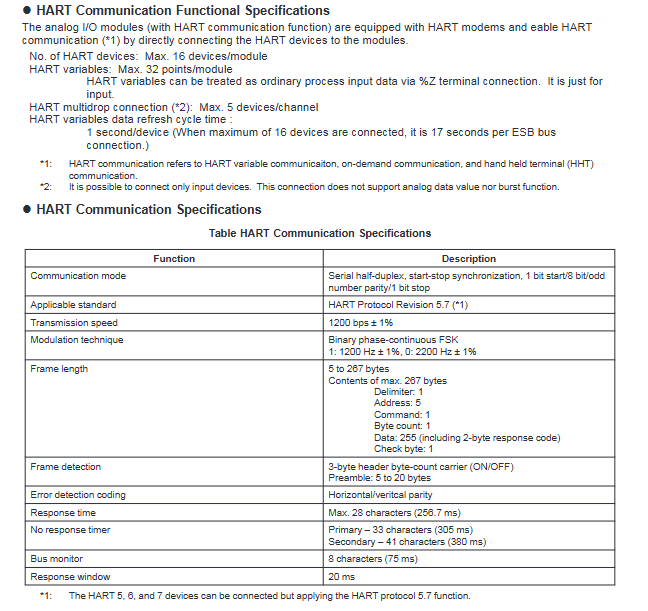
Communication parameters: 1200bps rate, serial half duplex mode, compatible with HART Protocol Revision 5.7;
Connection capability: up to 16 devices/modules, supporting 5 devices/channels for multi station connection (input devices only);
Data processing: HART variables are connected through the% Z terminal and only support input. The data refresh cycle is 1 second per device;
Redundancy support: Can be configured with dual redundancy, consistent with the installation requirements of ordinary modules.
Applicable scenarios: In explosion-proof environments where analog signal transmission and remote monitoring of equipment are required (such as in the petroleum and chemical industries), additional parameters of on-site equipment (such as equipment status and diagnostic information) can be read through the HART protocol without the need for additional wiring.
Question 3: What are the differences in the number of channels, accuracy, and current consumption among different types of modules? How to select based on demand?
answer:
Summary of core differences:
Module type Channel number Accuracy range 24V DC Current consumption
Analog input (ASI133) 8 ± 16 µ A 450mA
Analog output (ASI533) 8 ± 48 µ A 350mA
TC/mV input (AST143) 16 ± 40~80 µ V 80mA
RTD/BOT input (ASR133) 8 ± 150m Ω~± 2 Ω 60mA
Digital input (ASD143) 16- (NAMUR compatible) 110mA
Digital output (ASD533) 8- (10ms response) 500mA
Selection principle:
Signal type: Select AST143 (multi-channel TC/mV) or ASR133 (RTD/BOT) for temperature signal; Analog selection ASI133/533; Select ASD143/533 for switch quantity;
Accuracy requirement: Select ASI133 (± 16 µ A) for high-precision analog acquisition; Select AST143 (± 40 µ V) for temperature acquisition;
Power consumption limitation: ASR133 (60mA) or AST143 (80mA) is preferred for low-power scenarios;
Expansion requirement: Remote monitoring equipment with HART ASI133-H/ASI533-H needs to be selected.
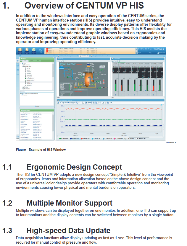
Ergonomic design: Adopting the concept of “Simple&Intuitive”, unifying icons and colors, reducing the physical and mental burden of operation
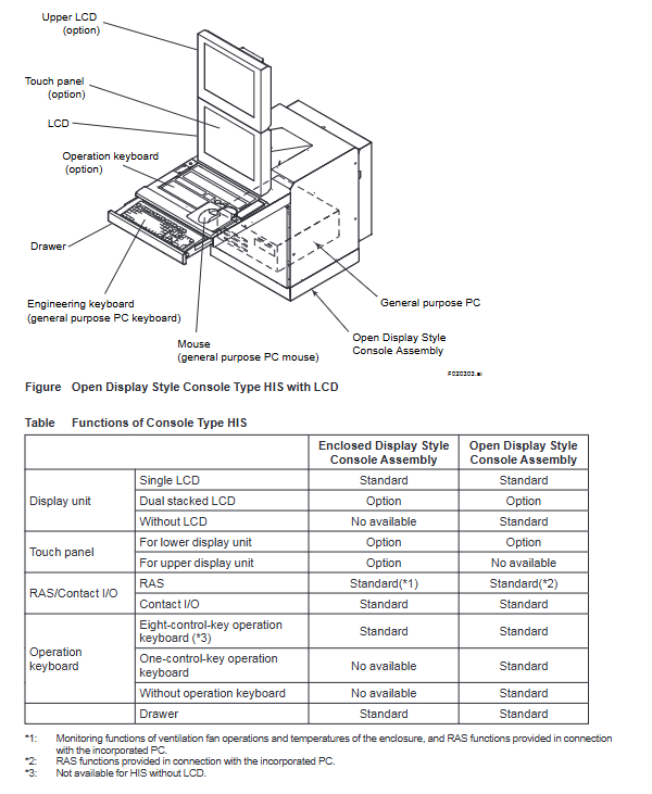
Multi monitor support: 1 HIS can connect up to 4 monitors, and supports single button switching of monitor display content
High speed data update: The data collection and update speed is as fast as 1 second, meeting the manual control requirements for pressure and flow
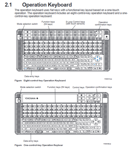
Operational inheritance: compatible with traditional HMI operation methods, supporting touch operation, 8 control keys, and 64 function keys
Cross system integration: can integrate alarms and events from ProSafe RS, STARDOM, PRM and other systems
2. Hardware composition
Operation keyboard: two types (8-key control type, 1-key control type), using flat key design, supporting one click operation
Core buttons: 64 function keys, mode selection switch, operation confirmation key, data input key
Special design: 8-key control type with touch sensor, suitable for high-frequency operation in industrial scenarios
Host configuration: Pre installed Microsoft Windows system, supports widescreen display, compatible with multi interface expansion
Core functions of operation and monitoring
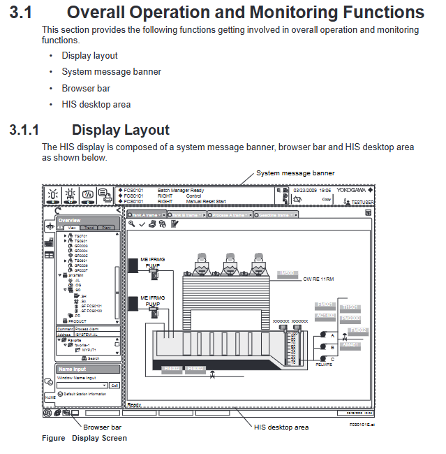
1. Overall display layout
The HIS display interface consists of three parts, with a fixed layout that does not obstruct each other:
System message bar: Permanent at the top, displaying alarm status through color/flashing, including date and time, username, and system status icon
Browser Bar: Used to call the operation monitoring window, supports tree display of factory hierarchy structure, and can minimize hiding
HIS desktop area: the core display area, including views, frames (up to 4 views/frames), container windows, and supports multi label switching
2. Core operation monitoring window
Window Type Core Function Key Parameters
Graphic view (graphic properties) visualizes the factory status with drawing objects and supports window calling to visually present device connections and operating parameters
Graphic view (controlling properties) displays the status of functional blocks on the dashboard, supporting parallel display of 8 large-sized/16 small-sized panels
Compact display of data values, function block modes, alarm status coverage PVI input, PID control, MLD manual loading and other multiple module types in panel view
Trend view time series display process data changes support simultaneous display of 8/16 pieces of data, with three split screen modes (pen split/simulated discrete split/reference mode split)
Tune view displays instrument tuning parameters and trends, supports time and data axis scaling adjustments
CAMS for HIS message monitoring integrates multiple system alarms and event support with intelligent filtering functions such as filtering, shelving, and suppression
3. Auxiliary support function
Report function: Generate daily/monthly reports based on Microsoft Excel, supporting automatic (timed/triggered) or manual printing
Imported data: settlement data (mean/total/maximum), trend data, historical messages, tag information, etc
Remote printing: supports other PCs within the network to print reports through Excel
Remote operation and monitoring: Implement remote operation and maintenance through the intranet, using the same operation window as the local HIS
Deployment requirements: The control network needs to be equipped with standard HIS to ensure reliability and real-time performance
CENTUM Desktop: A dedicated operating environment that hides Windows redundant features such as desktop icons and unrelated start menu items
HIS Utility tool: Configure the HIS operating environment, support user management, keyboard operations, security policies, CAMS parameters, and other settings
System management and security control
1. System management window
Window Name Core Usage Key Features
The system status overview displays the status of all sites and communication devices within the domain in a visual representation of normal/abnormal status through icons, and supports calling maintenance windows
The system alarm view displays hardware/communication error alarms arranged in reverse chronological order, accompanied by beeps and flashing prompts when triggered
The FCS status display view displays the hardware configuration and operational status of FCS, supports starting/closing control stations, and color coded device status
The HIS status display view shows the hardware configuration and operational status of HIS, and supports the effectiveness of switching control buses (Vnet/IP)
The HIS settings window includes 18 configuration tags (monitor, printer, trend, multi monitor, etc.) for configuring HIS operating parameters
2. Safety control system
Adopting a dual layer architecture of “CENTUM dedicated security+Windows IT security”:
CENTUM dedicated security:
Permission classification: Level 3 standard permissions (S1 for monitoring only, S2 for monitoring+operation, S3 for full permissions)+Level 7 custom permissions (U1-U7)
Control granularity: Support setting operation permissions by function block and window, important operations require secondary confirmation
Tag priority: can mark important tags, ordinary tags, auxiliary tags, and differentiate alarm processing
IT security features:
Security Model: Supports traditional models, standard models (defense against network/direct attacks), and enhanced models (full threat defense)
Advanced features: password expiration (14 day advance reminder), prohibition of duplicate passwords, automatic logout (no operation timeout), user lockout (multiple password errors)
Authentication mode: Supports Windows single sign on, integrates Windows user accounts and HIS operation permissions
CAMS for HIS Alarm Management Core Function
As a core alarm management tool, following the EEMUA 191 standard, it solves the problem of alarm overflow:
1. Alarm integration and filtering
Integration scope: CENTUM VP process alarms, system alarms, operator guide messages, and external system alarms such as ProSafe RS and STARDOM
Filtering function: Basic filtering (process/system alarms), user-defined filtering, temporary filtering, supporting sorting by priority/response time
2. Intelligent alarm processing
Suspend function: Move non essential alarms to a temporary area and support manual/automatic shelving (triggered by conditions)
Suppression function: Suppress message display according to preset alarm groups/sites, reducing operation and maintenance load
Alarm setting value management: Save the engineering stage setting value as the benchmark value, support comparing the benchmark value with the current value, and overwrite updates
3. Data archiving and traceability
Support long-term data archiving, with the ability to trace alarm records through a historical viewer
Alarm details: including value-added information such as root cause analysis, role-playing suggestions, historical operation processes, etc
Applicable scenarios and industries
Applicable industries: factories in various fields such as petroleum refining, chemical industry, steel, food, electricity, etc
Core value: By visualizing operations, intelligent alarm management, and remote operation and maintenance, we aim to improve the efficiency and safety of factory operations, and support rapid decision-making
Key issues
Question 1: How does HIS’s multi display support and data update feature meet the high-frequency operation requirements of industrial scenarios?
answer:
Multi monitor support: One HIS can connect up to four monitors and support single button switching of display content. It can simultaneously display various types of windows such as graphic views, trend views, alarm monitoring, etc., avoiding frequent window switching and adapting to the parallel monitoring needs of multiple parameters in industrial scenarios;
Data update performance: The data collection and display update speed is as fast as 1 second, meeting the real-time requirements of manual control of key parameters such as pressure and flow, and ensuring synchronization between operation instructions and feedback;
Hardware adaptation: The dedicated operation keyboard adopts a flat key design and one key operation logic. The 8-key control type includes a touch sensor, which reduces the fatigue of high-frequency operations and improves operation accuracy.
Question 2: As a core alarm management tool, how does CAMS for HIS solve the problem of alarm flooding in industrial scenarios?
Intelligent processing mechanism: Reduce the number of alarms by “shelving” (temporarily hiding non essential alarms), “suppressing” (blocking redundant alarms by group/site), and “overlapping merging” (integrating duplicate alarms on the same label);
Value added information support: Alarm with root cause analysis and role-playing suggestions, helping operators quickly locate problems and avoid ineffective operations;
Set value management: Compare the benchmark alarm set value with the current value, promptly correct unreasonable settings, and reduce false alarms from the source.
Question 3: How does HIS’s dual layer security control system ensure the operational safety of industrial control systems?
answer:
Fine grained control of permissions: CENTUM’s dedicated security support divides the scope of operations according to user groups (such as specific FCS/windows), restricts operation permissions (monitoring/operation/engineering) according to permission levels (S1-S3+U1-U7), and requires secondary confirmation for important function block operations;
IT Security Enhancement: Implementing user account control based on Windows security features, supporting password expiration, prohibiting duplicate passwords, automatic logout, and defending against illegal login and password leakage;
Security model adaptation: Three security models (traditional/standard/enhanced) are provided, which can be selected according to the risk level of the factory. The standard model defends against network and direct attacks, while the enhanced model covers component theft and data leakage protection;
Operation traceability: User operation records are bound and archived with usernames, supporting security event traceability for easy responsibility identification and risk investigation.
AFV10 (AFV10S/AFV10D) 19 inch rack mounted (single/dual redundant) supports ESB/ER bus, connecting up to 14 node units ESB bus, ER bus
AFV30 (AFV30S/AFV30D) 19 inch rack mounted (single/dual redundant) supports ESB/optical ESB bus, and EC401/EC402 coupling module ESB bus and optical ESB bus need to be installed
AFV40 (AFV40S/AFV40D) with cabinet (single/double redundancy) standard configuration EC401/EC402, with a maximum of 11 node units ESB bus and optical ESB bus in a single cabinet
2. Node units and relay units
Type, Model, Usage, Core Parameters
ESB bus node units ANB10S/ANB10D single/dual redundant ESB bus connections support all I/O modules, and dual redundancy needs to be installed in pairs
Optical ESB bus node unit ANB11S/ANB11D single/dual redundant optical ESB bus connection with built-in optical relay module, supporting long-distance transmission
ER bus node units ANR10S/ANR10D single/dual redundant ER bus connections only support specific I/O modules (such as ADV151-P)
Optical ESB relay unit ANT10U Optical ESB bus relay extension installation Optical relay module (ANT401/ANT411, etc.), supporting chain/star topology
3. Classification and Key Specifications of I/O Modules
Module type represents model, number of channels, isolation type, explosion-proof level
Analog input module AAI141 (4-20mA) 16 channel non isolated CSA NI, FM NI
Analog output module AAI543 (4-20mA) 16 channel isolated Type n, Type i
Digital input module ADV151 (24V DC) 32 channel isolated CSA NI, FM NI
Digital output module ADV551 (24V DC) 32 channel isolated Type n, Type i
Communication module ALR111 (RS-232C) 2-port non isolated CSA NI, FM NI
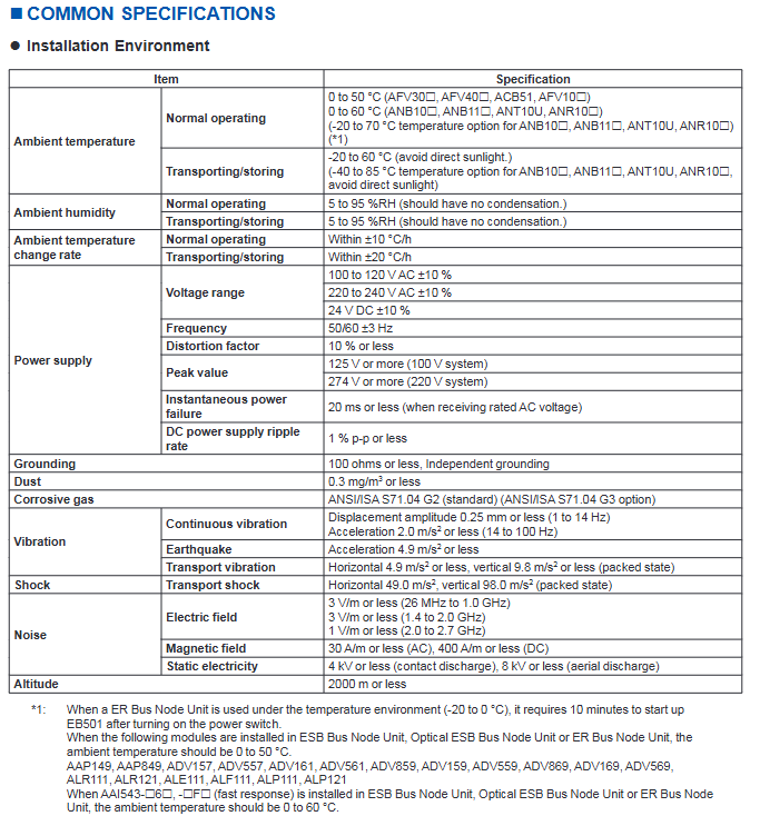
Power type, voltage range, frequency/ripple, instantaneous power-off tolerance
AC power supply 100-120V AC ± 10%, 220-240V AC ± 10% 50/60Hz ± 3Hz, distortion rate ≤ 10% ≤ 20ms
DC power supply 24V DC ± 10% ripple ≤ 1% p-p-
The grounding requirement is independent grounding, with a grounding resistance of ≤ 100 Ω —
Installation restrictions and connection methods
1. Module installation restrictions
Power capacity limit:
Non hazardous area: Node unit module factor B sum ≤ 100;
Dangerous zone (ANB10 - E): total factor B ≤ 88;
Dual redundant FCU (AFV10D/AFV30D): Factor A sum ≤ 5, Factor A+B sum ≤ 65.
Temperature related restrictions:
In an environment of 60-70 ℃, each node can install up to 4 I/O modules, and slots need to be left empty between modules;
AAP149, ADV157 and other modules only support 0-50 ℃, while AAI543- 6 (quick response) supports 0-60 ℃.
Safety distance limit:
The distance between the built-in isolation barrier module and other modules is ≥ 50mm, and an insulation partition (T9083NA/T9083ND) needs to be installed;
AAT141 (thermocouple input) needs to be kept away from the heat source, and only specific modules (such as AAT145, AAR181) can be installed adjacent to it.
2. Signal connection method
Connection type applicable module media requirements representative accessories
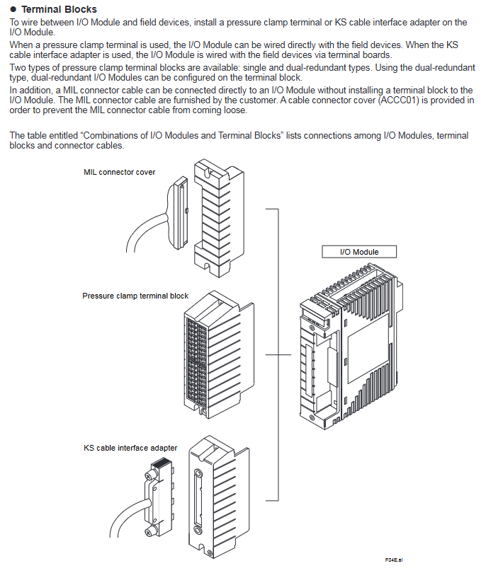
Most analog/digital modules with pressure clamp terminals have a conductor cross-sectional area of ≤ 1.25mm ². ATA4S (single redundancy) and ATA4D (double redundancy) are available
Special cable compatible with ST series module Yokogawa special cable (such as AKB331) ATK4A adapter, KS1 cable
MIL connector cable specific analog module (such as AAI141), customer provided, requires cable connector cover (ACCC01) D-sub 9-pin, M4 terminal block
3. Requirements for dual redundancy configuration
I/O modules need to be installed in adjacent slots (IO1-IO2, IO3-IO4, etc.);
A dual redundant terminal block (such as ATA4D) connects two adjacent I/O modules;
The dual redundancy of communication modules (such as ALR111) needs to be configured according to communication functions, with a maximum of 8 pairs per FCU.
Compliance standards
Safety standards: CSA, CE Marking, EAC Marking (excluding some modules such as ADR541);
Question 1: What are the core differences between the three communication buses (ESB/Optical ESB/ER) supported by the FIO system? What are the applicable scenarios?
answer:
Core Differences:
Comparison Dimension ESB Bus Optical ESB Bus ER Bus
Transmission rate 128Mbps 128Mbps 10Mbps
Transmission medium specific cable (YCB301) Single mode fiber coaxial cable (YCB141/YCB311)
ESB bus: close range (≤ 10m), high transmission rate requirements, suitable for connecting AFV full series FCUs and node units;
Optical ESB bus: Long distance (≤ 50km), anti-interference requirements, suitable for long-distance node expansion of AFV30 /AFV40 ;
ER bus: Medium distance (≤ 185m), low-cost requirement, only applicable to standard FCS configuration of AFV10 .
Question 2: What conditions must be met for the dual redundancy configuration of FIO system I/O modules? How to ensure the effectiveness of redundancy?
answer:
Configuration conditions:
Module installation: I/O modules need to be installed in pairs in adjacent slots (IO1-IO2, IO3-IO4, etc.), with dual redundant terminal blocks (such as ATA4D) connected accordingly;
Module model: It is necessary to use I/O modules that support dual redundancy (modules marked with “X” in the document, such as ADV151 and AAI543), and some modules (such as ADV141) do not support dual redundancy;
Node unit: Dual redundant node units (ANB10D/ANB11D/ANR10D) are required, and single redundant node units (ANB10S, etc.) cannot achieve module dual redundancy;
Bus configuration: The ESB/optical ESB/ER bus needs to enable dual redundancy function, and the FCU needs to install the corresponding dual redundancy coupling module (such as EC402).
Effectiveness guarantee:
The control side and backup side module models and software versions are consistent;
The signal connection needs to be established through dual redundant terminal blocks to ensure signal synchronization on both sides;
Verify the redundant switching function (dual redundant FCU scenario) through APC (Automatic Phase Control) after installation.
Question 3: What module selection and installation requirements should be focused on when installing FIO systems in hazardous environments (explosion-proof requirements)?
answer:
Module selection requirements:
Prioritize selecting modules that support explosion-proof ratings: Type i (intrinsic safety) or Type n (spark free), such as ASI133 (Type i), AAI543 (Type n);
Dangerous areas require the use of I/O modules with built-in isolation barriers (such as ASI133, ASD143) to avoid external isolation barrier configurations;
Exclude modules that do not support explosion-proof, such as ADR541 which does not support Type n and ARS series modules which do not support CE/AAC explosion-proof standards.
Installation requirements:
Distance isolation: The distance between the built-in isolation barrier module and the non intrinsic safety module is ≥ 50mm, and an insulation partition (ANB10 using T9083NA, AFV10 /AFV30 using T9083ND) needs to be installed;
Power restriction: The total factor B of the hazardous area node unit module is ≤ 80 (ANB10 - F) or ≤ 88 (ANB10 - E);
Environmental adaptation: Select G3 level corrosive gas protection module, temperature range follows -20-60 ℃ (extended option);
Wiring specification: Use explosion-proof certified cables with a conductor cross-sectional area of ≤ 1.25mm ², connected from the CH1 terminal.
Backup and export NFCP100/NFJT100 data, FcxBackup all – u<username>- p<password><IP/hostname>, generate a “ACKUP” folder containing resource configuration, DUONUS.PRP, etc
Convert to NFCP500 format FcxConvert – t<NFCP501/NFCP502>- i<source folder>- o<destination folder>NFJT100 backup file cannot be converted, I/O needs to be reset
Before restoring the import of NFCP500 FcxRestore<IP/hostname>, the target folder needs to be renamed to “ACKUP” and the SRAM cleared to preserve data
Assist in clearing and holding data FcxSaveRetain-c<IP/hostname>to ensure that the backed up data is correctly mapped to SRAM
2. Control application migration
Project upgrade: R1-R3 format project automatically converts to R4 format after opening, R4 project is not backward compatible
Resource reconstruction rules (by PLC type):
Notes on PLC type processor type migration operation
IPC_40 FCX/FCX_A can be recompiled directly without modifying the project
IPC40 FCX_B/FCX_C reconstruction resources (IPC40+FCX_B/FCX_C)+compilation extension to maintain data area usage
IPC_32/IPC_33- Rebuilding resources (PLC type changed to IPC_40)+Definition of tasks/variables/labels to be copied for compilation
SH_40- Rebuilding resources (changing PLC type to IPC_40)+compiling compatible with existing functions
Download requirements: Offline download of the control application is required, and the startup project and source files should be downloaded as needed
3. Comparison of two migration modes
Advantages of core steps in applicable scenarios
Directly migrating to the on-site environment is simple and does not require pre validation of A1 (acquisition tool) – A10 (APC execution). The 10 step process is concise and does not require internal device support
The pre migration site environment is complex, and it is necessary to verify the site (B1-B3) → internal (B4-B10) → site (B11-B16) in advance, with a total of 16 steps to reduce the risk of on-site downtime and identify problems in advance
Special configuration migration
1. New feature settings (exclusive to NFCP500)
Need to configure through Resource Configurator: CPU dual machine hot standby, SNTP server, 3/4 Ethernet port of NFCP502, SD card, Duolet function
2. Field bus migration (NFLF111/NFLP121/NFLC121 modules)
Need to copy and import configuration files: FOUNDATION field bus (CF/DD file), PROFIBUS (GSD file), CANopen (EDS file)
Original project PC → New project PC: Export resource configuration → Import configuration → Download to NFCP500
3. Duolet (Java) application migration
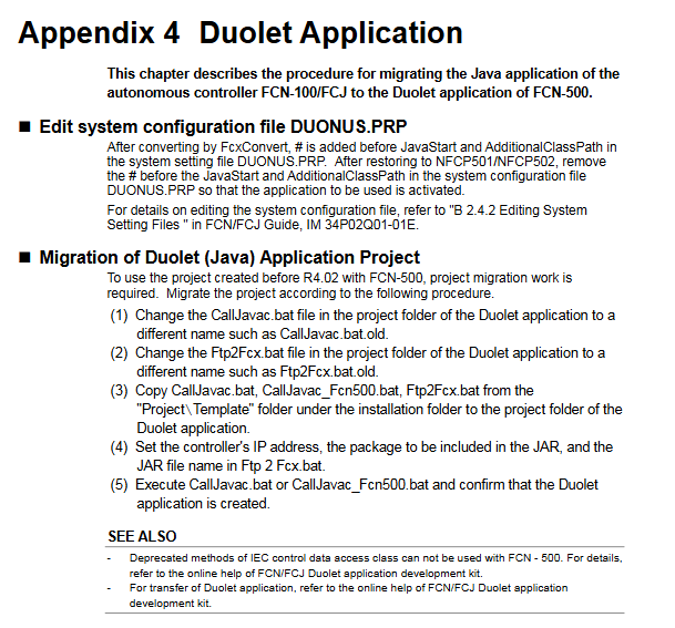
Edit DUONUS.PRP: Remove the “#” comment before JavaStart and AdditionalClassPath
Replace batch files: CallJavac.bat, Ftp2Fcx.bat (copied from installation directory template)
Configuration parameters: Set controller IP, JAR package information, perform compilation validation
Key Limitations and Precautions
License: Cannot be migrated from the original device, NFCP500 CPU module with pre bundled required license must be used
Keep data: When expanding the hold data area, the hold data saved by the original NFCP100 is unavailable
Port adaptation: The COM2 of FCJ needs to be migrated to the RS-232C communication module, and the port name in the program needs to be changed to “RS02”, etc
Dual machine hot standby: The control side and standby side CPUs must be of the same model and have the same basic software version. After migration, APC must be executed
Key issues
Question 1: What are the differences in core operations for different PLC types (IPC32/33/40) when controlling application migration?
answer:
IPC40 (processors FCX/FCX_A): No project modification required, simply recompile to adapt to NFCP500; If you need to expand and maintain the data area, you need to rebuild the resources as “IPC40+FCX_B/FCX_C” and compile them.
IPC32/IPC33: It is necessary to rebuild the resources (change the PLC type to IPC40), and copy the task definitions, global variables, device labels, software wiring, and other configurations of the original project before compiling and downloading.
The core difference lies in whether resources need to be rebuilt. The root cause is that NFCP500 is only compatible with IPC40 and above PLC types, and lower version PLC types need to be upgraded and adapted.
Question 2: What are the applicable scenarios and core differences between the two migration modes (direct migration vs pre migration)?
answer:
Applicable scenarios: Direct migration is suitable for scenarios where on-site downtime is allowed and the environment is simple (without complex field buses or special applications); Pre migration is suitable for complex on-site environments (including field buses and Duolet applications) that require minimizing downtime risks.
Core difference: Pre migration adds an “internal device verification” step (steps B4-B10), which allows for early completion of data conversion, application compilation, and functional testing. On site, only CPU replacement, data recovery, and application download need to be performed; Direct migration means that all operations are completed on the target device on site without pre validation, resulting in a simpler process but higher risks.
Question 3: How to migrate the configuration of the field bus module (NFLF111/NFLP121/NFLC121) during the migration process? What should I pay attention to?
answer:
Migration steps: ① Export field bus definition information from the original project PC (NFCP100); ② Copy the configuration files (CF/DD/GSD/EDS) to the new project PC (NFCP500); ③ Import definition information and download it to NFCP500; ④ Verify the field bus communication function.
Attention: ① If using FF engineering tools before R2.20, the configuration needs to be converted to FF configurator format first; ② The field bus definition information is bound to the controller IP, and when replacing the project PC, “export import” must be performed. Upgrading the same PC does not require any operation; ③ After migration, it is necessary to focus on verifying the communication connectivity of field bus devices to avoid configuration omissions.
Basic modules: 6 models (F3BU04-0N to F3BU16-0N), 4-16 slots, supporting different module combinations
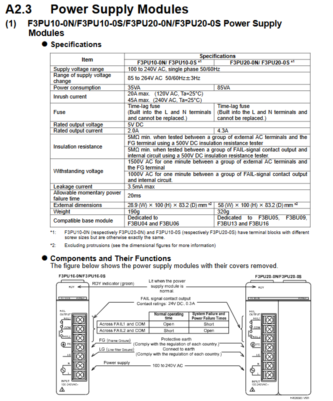
Power module: AC input (F3PU10/20/30 series), DC input (F3PU16/26/36 series), output voltage 5V DC, rated current 2.0A-6.0A
CPU module: including sequential CPU, BASIC CPU, OS free CPU, etc., instruction execution time 0.00375 μ s-0.36 μ s/step, program capacity 5K-254K steps
I/O modules: digital (input/output/hybrid), analog (input/output), special modules (temperature control, positioning, communication, etc.), with 8-64 points per module
Expansion modules: Fiber FA bus module, communication module (Ethernet, PROFIBUS-DP, etc.)
2. System topology
Main unit: Must contain 1 CPU module, unit number 0, supports up to 3 extended CPU modules
Slave unit: No CPU module, up to 7, connected to the main unit through a bus, with a maximum of 8192 I/O points per system
Expansion distance: The maximum length of a single section of fiber optic cable is 500m, and the maximum length of a twisted pair cable is 70m
Key technical parameters
1. Environmental and physical parameters
Category specifications
Working temperature 0-55 ℃ (some modules require a narrower range)
Storage temperature -20-75 ℃
Relative humidity 10-90% RH (non condensing)
Installation requirements for indoor use, metal panel enclosure (IK08 and above)
The highest altitude is 2000m
Anti vibration 10-57Hz amplitude 0.075mm, 57-150Hz acceleration 9.8m/s ²
2. Electrical parameters
Power supply fluctuation: AC power supply 85-264V, DC power supply 15.6-31.2V
Insulation resistance: ≥ 5M Ω (tested at 500V DC)
Voltage resistance strength: 1500V AC/1 minute (power terminal – ground)
Leakage current: ≤ 3.5mA (AC power supply)
Allow instantaneous power outage: up to 20ms (standard mode)
3. Performance indicators
CPU processing speed: Basic instructions 0.0175 μ s-0.36 μ s/step (depending on model)
I/O response time: The fastest digital quantity is 50 μ s, and the fastest high-speed module is 0.1ms
Communication speed: Ethernet up to 100Mbps, PROFIBUS-DP up to 12Mbps
Scalability: Supports up to 7 slave units and 32 FA link H module sites
Installation and wiring specifications
1. Installation requirements
Fixing method: DIN rail installation (F3BU04/06/05/09/13) or M4 screw fixation (all models)
Module installation: Power off operation, the module needs to be clamped to the locking buckle, and additional screws are required to fix it in the vibration environment
2. Wiring specifications
Conductor requirements: Only copper conductors are allowed, with a cross-sectional area of 0.33-2.1mm ² (AWG14-22)
Terminal torque: M3 screw 0.8N · m, M4 screw 1.2N · m
Anti interference measures:
The distance between signal cable and power cable is ≥ 20cm
Analog signal and digital signal slot wiring
Shielded cable with both ends grounded, bending radius ≥ 50mm (fiber optic)
Grounding requirements:
Protective grounding (FG): connected to the protective grounding grid, cable ≥ 2mm ²
Battery: The serial CPU module is equipped with a built-in lithium battery, which has a lifespan of ≥ 10 years at room temperature
Module: Preventive replacement is required after more than 10 years of use
Fuse: 3.15A Delay Fuse (Model A1113EF)
Fault handling: Check the error code through the CPU self diagnostic function. Core errors include module communication failure, power supply abnormality, I/O short circuit, etc
Safety precautions
Power off operation: The power must be turned off before wiring or plugging in modules
Prohibition of modification: It is not allowed to modify the internal circuit or shell of the module
Load limit: The output module must not exceed the rated current (transistor type 0.1A-2A/point, relay type 2A/point)
Environmental protection: Avoid corrosive gases, flammable gases, and radioactive environments
Emergency circuit: An external relay is required to achieve interlocking of the emergency stop circuit
Key questions and answers
Question 1: What is the maximum scalability of the FA-M3 controller? What extension methods are supported?
answer:
Maximum Expansion: The main unit (No. 0) can connect up to 7 slave units (No. 1-7), with a maximum of 8192 I/O points per system (depending on the CPU module model)
Expansion method:
Fiber optic FA bus type 2 module: using fiber optic cables, with a maximum length of 500m per section, strong anti-interference ability
FA bus type 2 module: using shielded twisted pair cables, with a maximum length of 70m per segment, at a lower cost
Local expansion: The basic module supports 4-16 slots, allowing for direct expansion of local I/O modules
Question 2: What are the key requirements for grounding and anti-interference when installing the FA-M3 controller?
answer:
Grounding requirements:
Protective grounding (FG terminal): connected to a protective grounding grid that meets national standards, with a grounding resistance of ≤ 100 Ω and a cable cross-sectional area of ≥ 2mm ²
Functional grounding (FG terminal): To ensure stable operation, grounding is necessary, and CE compliance requires the use of braided wire to ensure high frequency and low impedance
Shielding layer grounding: The two ends of the signal cable shielding layer are grounded and fixed to the metal panel through FG fixtures
Anti interference requirements:
Cable separation: The distance between power cables and signal cables should be ≥ 20cm, and analog and digital signals should be routed in separate slots
Cable selection: Use shielded twisted pair or fiber optic cables to avoid parallel laying with power cables
Filtering measures: The power module is equipped with a built-in noise filter, and sensitive modules can be additionally equipped with ferrite cores
Question 3: What are the types of power modules for the FA-M3 controller? How to choose a suitable power module?
answer:
Power module type:
Type Model Series Input Voltage Rated Output Applicable Basic Module
AC input F3PU10/20/30 100-240V AC 5V DC, 2.0A/4.3A/6.0A F3BU04/06 (10 series); F3BU05/09/13/16 (20/30 series)
DC input F3PU16/26/36 24V DC 5V DC, 2.0A/4.3A/6.0A F3BU04/06 (16 series); F3BU05/09/13/16 (26/36 series)
Selection principle:
Based on the basic module model: 4/6 slot basic module selects 10/16 series, 5/9/13/16 slot selects 20/26/30/36 series
According to power requirements: total current consumption ≤ rated output current of the power supply (all module current consumption needs to be added)
According to the installation environment: CE compliance requires selecting models with the suffix “S” (such as F3PU10-0S)
Based on power supply stability: AC input module is preferred for scenarios with large fluctuations (allowing 85-264V wide range)
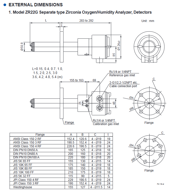
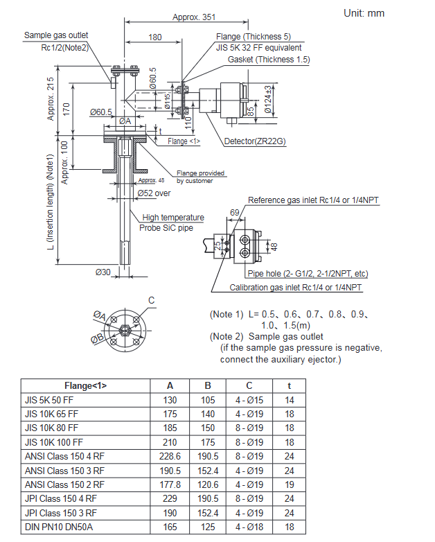
Type: Universal type (sample temperature range 0-700 ℃), High temperature type (0.15m probe, paired with ZO21P adapter, sample temperature range 0-1400 ℃)
Probe length: 0.15-5.4m (excluding 0.15m for humidity analyzer), material: SUS316 (universal type), SiC/SUS310S (high temperature type)
Protection level: equivalent IP44D (universal type), IP66 (pressure compensation type, when cable is sealed)
Humidity (volume fraction) 0-100 vol% H ₂ O repeatability ± 1 vol% H ₂ O (sample gas pressure ≤ 2kPa)-
Humidity (mixing ratio) 0-1.000 kg/kg —
Core operating procedures
(1) Installation and wiring
Installation requirements:
Environment: Detector ambient temperature -20-150 ℃, converter -20-55 ℃, no corrosive gases, no vibration
Probe installation: For lengths ≤ 2m, it can be installed horizontally to vertically. For lengths ≥ 2.5m, it needs to be installed vertically (± 5 °). High temperature SiC probes need to be installed vertically
Flange specifications: Supports JIS, ANSI, DIN and other standards, and needs to be matched with equipment models
Wiring specifications:
Cable: 6-core shielded cable for detector signal (two-way resistance ≤ 10 Ω), 2-core cable for heater, temperature resistance ≥ 80 ℃
Partition wiring: separate signal cables from power/heater cables to avoid interference
(2) Calibration process
Calibration preparation:
Gas requirements: Zero gas (0.95-1.0 vol% O ₂+N ₂), span gas (dry and clean air, dew point ≤ -20 ℃)
Flow setting: Calibrate air flow rate of 600 ± 60 ml/min, reference air flow rate of 800-1000 ml/min
Calibration mode selection:
Manual calibration: Gas valve is manually controlled through ZO21S/ZA8F unit, suitable for system 1/2
Semi automatic calibration: Start with touch panel or touch input, complete calibration according to preset time
Automatic calibration: System 3 dedicated, automatically executed at set intervals (up to 255 days)
Core steps:
Span calibration: Introduce span gas and confirm calibration after the value stabilizes
Zero calibration: Introduce zero gas and complete calibration in the same way
After calibration: Close the calibration gas valve and wait for the output to stabilize (default 10 minutes)
(3) Key points for safe operation
Power safety: Confirm that the power supply voltage matches the rated value of the equipment (100-240V AC), and disconnect the power before wiring
High temperature protection: The working temperature of the detector probe reaches 750 ℃, and gloves should be worn during maintenance to avoid direct contact
Gas safety: Calibration gas/sample gas may be toxic, ventilation or protective mask should be worn during maintenance, and pipelines should be checked for leaks
Sensor protection: The sensor is made of ceramic material to avoid impact and pressure, and direct contact with water droplets is prohibited
Maintenance and troubleshooting
(1) Regular maintenance
Daily maintenance: Clean and calibrate the gas pipeline (anti clogging), check the filter (K9471UA dust filter)
Regular replacement: Sensor components (according to the calibration coefficient, zero gas calibration proportional to 100 ± 30% and span gas calibration proportional to 0 ± 18% are normal), metal O-rings (must be replaced when replacing sensors), heater units (when resistance is abnormal)
Cycle: It is recommended to conduct regular inspections at intervals not exceeding those specified in the equipment manual, and the calibration cycle should be adjusted according to the usage scenario
(2) Common faults and their solutions
Key points for troubleshooting fault types, fault codes/phenomena
Cell voltage fault Error 1: Check the CELL ± wiring, whether the sensor is damaged, and the internal wiring of the detector
Heater temperature fault Error 2: Check the heater resistance (≤ 90 Ω), thermocouple wiring, and cold end temperature (-25-155 ℃)
Zero calibration coefficient alarm Alarm 6 confirms that the zero gas concentration is consistent with the set value, the gas flow rate is normal, and the sensor is not contaminated
High measurement value (oxygen analyzer) – check whether the reference gas humidity is stable, whether the calibration gas leaks, and whether the sample gas pressure is abnormal
Other key information
Product disposal: Local/national environmental regulations must be followed, and batteries must be classified and recycled (EU/UK region)
Spare parts list: Key spare parts include sensor components (E7042UD/ZR01A01), fuses (A1113EF, 3.15A), and metal O-rings (K9470BJ)
Key issues
Question 1: What are the core differences between the three system configurations of ZR22G and ZR402G analyzers? What scenarios are they applicable to?
Answer: The core difference lies in the calibration method and auxiliary equipment configuration, which are applicable in the following scenarios:
System 1: Only includes detector+converter+ZO21S standard gas unit, without fixed calibration gas pipeline, requiring manual connection of calibration gas, suitable for simple humidity monitoring scenarios such as small boiler oxygen concentration monitoring and food production;
System 2: Add ZA8F flow setting unit, zero gas cylinder, pressure reducing valve, reference gas is instrument air, support manual precise calibration, suitable for scenarios such as large boilers and heating furnaces that require regular manual calibration;
System 3: Replace with ZR40H automatic calibration unit, support timed automatic calibration, including combustible gas detection contact input (cutting off heater power), suitable for scenarios such as large industrial furnaces that require long-term stable operation and reduce manual intervention.
Question 2: How to determine if the sensor (zirconia cell) needs to be replaced? What are the key points to pay attention to when replacing?
answer:
Replacement criteria: ① The calibrated zero gas calibration ratio exceeds 100 ± 30% or the span gas calibration ratio exceeds 0 ± 18%; ② In the detailed data display, the cell internal resistance significantly increased (new sensor ≤ 200 Ω, reaching 3-10k Ω after aging); ③ Cell robustness shows’ life<1 month ‘; ④ The sensor has cracks, corrosion, or impact damage.
Replacement precautions: ① Operate after the detector has completely cooled down to avoid high-temperature burns; ② The metal O-ring (K9470BJ) and contact (E7042BS) must be replaced and old parts cannot be reused; ③ When installing the sensor, the four fixing bolts should be tightened evenly (with a torque of about 5.9 N · m) to avoid uneven force damage; ④ After replacement, the calibration process needs to be re executed to ensure measurement accuracy.
Question 3: What is the highest priority troubleshooting step when the device displays Error 2 (heater temperature fault)? What are the corresponding criteria for judgment?
Answer: The steps and criteria for priority screening are as follows:
Firstly, check the polarity of the thermocouple wiring: confirm that the detector TC+is connected to the converter TC+, and TC – is connected to TC -. If connected incorrectly, it will directly cause abnormal temperature detection, which is the most common cause;
Measure heater resistance: Disconnect the HTR terminal of the detector and measure the resistance value. The normal value should be ≤ 90 Ω. If the resistance value is too high, the heater will be disconnected and the heater unit needs to be replaced;
Check thermocouple resistance: After the detector cools down to a temperature difference of ≤ 50 ℃ from the environment, measure the TC ± terminal resistance. Normally, it should be ≤ 5 Ω. If it is>5 Ω, the thermocouple will break and the heater unit needs to be replaced;
Check the cold end temperature: Check the C.J. temperature through detailed data display. The normal temperature should be between -25-155 ℃. If it exceeds, check the cold end sensor or wiring.
CENTUM CS 1000 is a distributed control system developed by Yokogawa for small and medium-sized factories, with the core goal of reducing total cost of ownership (TCO) while balancing high functionality and maintainability. The design concept is to integrate the high-quality control functions of the CENTUM CS series that have been verified on site, strengthen the communication adaptation capabilities with various subsystems such as programmable logic controllers (PLCs), and solve the core pain points of small and medium-sized factories in control system deployment and maintenance through innovative technologies such as engineering process simplification, communication flexibility, and test virtualization.
System core function configuration
(1) Overall architecture of control function
The system control function is highly integrated into each field control station (FCS), with functional blocks as the core to build basic control applications, forming a complete functional system covering control, input/output, management and monitoring. The specific architecture is as follows:
Specific description of the core components of the functional hierarchy
The minimum unit of the core control component function block control algorithm, including basic components such as PID controller and selector, supporting modular assembly
Expansion control module covers various control blocks including regulation control block, sequence control block, SFC (Sequential Function Diagram) block, calculation block, and panel block, adapting to diverse control requirements
The auxiliary management function unit monitoring function is grouped by process unit management function blocks, greatly simplifying the control and monitoring operations of single process units
The status feedback function sequence message and alarm provide real-time feedback on the system’s operating status, prompt abnormal information in a timely manner, and ensure operational safety
Universal control function universal switch provides standardized operation interface, suitable for conventional control scenarios
Input/output function process I/O implementation and signal input/output with general sensors and actuators, supporting data exchange of field devices
Input/output function communication I/O achieves signal transmission with external devices through universal communication interfaces such as RS-232C
(2) Reliability assurance design
The system continues the mature synchronous hot standby system of the CENTUM CS series, which is the core of ensuring control continuity
Working principle: The FCS operating system adopts a synchronous running mode between the primary and backup CPUs. When the primary CPU is working normally, the backup CPU synchronizes data in real time; When the main CPU stops due to a sudden failure, the backup CPU seamlessly takes over control tasks without interrupting control actions
Applicable scenarios: Especially suitable for batch production processes guided by sequence control, even during the switching process of duplex control processors, it can maintain control status continuously, avoiding production losses caused by downtime
The control application is composed of multiple functional blocks, but different functional blocks have significant differences in the internal resources (such as memory) and CPU load requirements of FCS. However, the memory resources of FCS are limited. If functional blocks are combined in an unordered manner, engineers need to have rich experience, estimate resource usage and CPU load in advance, and avoid exceeding the system’s carrying capacity. This undoubtedly increases the complexity and threshold of engineering design.
(2) Core Design and Advantages of FCS Template
1. Template types and adaptation scenarios
Yokogawa provides users with three types of preset database templates that accurately match typical application scenarios for small and medium-sized factories:
Adjustment control template: adapted to parameter adjustment scenarios of continuous processes (such as temperature, pressure, flow rate adjustment)
Sequence control template: adapted to batch production scenarios executed according to fixed processes (such as chemical batching, product assembly)
Monitoring Template: Suitable for scenarios that only require data collection and status monitoring (such as device operation status monitoring)
2. Core technical features
Intelligent resource allocation: The template has a built-in optimized database configuration that automatically allocates FCS memory resources based on functional block types, ensuring optimal resource utilization
Strict load control: The preset configuration strictly controls the CPU load to not exceed the limit, eliminating the need for users to manually calculate and reducing the difficulty of engineering design
Ready to use: Users can directly select corresponding templates based on actual application scenarios, without the need to build functional block combinations from scratch, greatly reducing the project cycle
On site communication flexibility design: adaptable to diverse devices
In response to the industry pain points of dispersed on-site control equipment, diverse data types, and inconsistent communication interfaces and protocols, CENTUM CS 1000 achieves flexible adaptation through two core designs:
(1) Separation of communication function and control application
1. Architecture design logic
Data storage isolation: External data obtained through communication is uniformly stored in a separate “communication I/O area”, which is divided into sub areas according to subsystems (such as subsystem 1 communication I/O area, subsystem 2 communication I/O area)
Data access method: Control the control block in the application to access the data in the communication I/O area (such as% WW0100. PV) through “relative address” or “user-defined tag”, without paying attention to the physical source of the data
Automatic data type recognition: The system automatically recognizes the type of each data item (integer, floating point, etc.) in the communication I/O area, and users do not need to manually set the data type when configuring control applications
2. Core advantages
Protocol independence: When the communication protocol is changed, only the communication module configuration needs to be adjusted without modifying the control application, reducing system modification and maintenance costs
Reduce coupling: control logic and communication logic are decoupled to improve system stability and reduce the impact of single module failure on the overall system
(2) C programming language adapted to multiple protocols
1. Protocol adaptation plan
Common protocols: Yokogawa has developed ready-made communication packages for mainstream communication protocols in the industrial field, which users can directly choose and quickly complete equipment docking
Special protocol: For niche or customized protocols, support users to develop communication programs through C language coding to achieve personalized adaptation
2. Communication data flow
On site equipment/subsystems are connected to FCS through a common communication interface
Communication program (ready-made communication package or user C language program) retrieves data and stores it in the communication I/O area
Control applications to access communication I/O areas through addresses or labels to achieve data exchange
Control instructions are transmitted in reverse to on-site devices/subsystems through the same path
Innovative virtual testing function: deep analysis of simulator system
(1) Design Objective
Without the need to build a complete physical FCS hardware environment, the design, testing, and verification of control applications can be completed solely through a personal computer (PC), reducing the cost of building engineering environments and improving project implementation efficiency.
(2) FCS Simulator: Core Virtual Testing Tool
1. Basic configuration
Operating environment: Windows NT operating system
Run mode: Run as an independent process, read the control application definition file generated by the engineering function
2. Core functions
Control action simulation: Fully replicate the control logic and execution process of actual FCS to ensure that test results are consistent with actual operation
Communication mechanism: Through “simulating internal VLnet communication”, interaction with PC side operation monitoring function (HIS function) and testing function is achieved. The operation logic is completely the same as connecting to the actual FCS, and users do not need to learn new operation methods separately
3. Internal operating mechanism
Modular design: Each FCS functional task (such as control tasks, communication tasks, trend tasks) is encapsulated as a dynamic link library (DLL) and loaded in thread form during runtime
Kernel adaptation: Built in FCS kernel simulation function (also encapsulated as DLL), its interface is completely consistent with the actual FCS kernel, ensuring the reusability of task source code and guaranteeing functional equivalence
Thread scheduling: After a thread calls the kernel simulation function, it triggers scheduling (scheduling point), and switches threads through the “suspend/resume” command of the Win32 API – the current thread first resumes other suspended threads, and then suspends itself to ensure the orderly execution of multitasking
Interrupt handling: Independent interrupt threads use Windows messages as trigger signals to pause the current task, execute interrupt handling, and resume scheduling after receiving the message, ensuring real-time interrupt response
(3) Inter Station Communication Simulator: Multi FCS Collaborative Testing Tool
1. Original design intention
Support control application testing that requires data interaction between multiple FCS, enabling multi-user parallel system engineering and improving overall design efficiency.
2. Working principle
Data reception: Receive all communication data packets sent by the FCS simulator to other FCS
Data processing:
When receiving data setting commands, save the corresponding request values
When receiving a data read command, return the preset response value
Interactive interface: Support users to view saved request values and set response values through a graphical user interface (GUI), with intuitive and convenient operation
3. Core advantages
Without the need to deploy multiple physical or virtual FCS, cross FCS control application testing can be completed without increasing the existing CPU load, significantly reducing the cost and complexity of multi system collaborative testing.
(4) Overall collaborative process of simulator system
Engineers design control applications through PC engineering functions and generate control application definition files
The FCS simulator loads the definition file and simulates the actual execution of control actions by FCS
If multiple FCS data interactions are involved, start the inter station communication simulator to simulate the response logic of other FCS
The operation monitoring function and testing function simulate internal VLnet communication and interact with the FCS simulator to conduct application testing
After the testing is completed, the control application can be directly deployed to the actual FCS without additional modifications
Core values and future prospects of the system
(1) Summary of Core Values
Specific manifestation of value dimension
Cost optimization: 1. Virtual testing function reduces the cost of building engineering environments; 2. FCS templates simplify the design process and reduce labor costs; 3. Communication and control separation design reduces maintenance costs
Efficiency improvement 1. Template based engineering design shortens project cycle; 2. Multi user parallel testing improves project implementation efficiency; 3. Control the application of “one-time design, two-way deployment” (simulator and actual FCS) to reduce repetitive work
Strong adaptability: 1. Supports multiple communication interfaces and protocols, and adapts to dispersed and diverse on-site devices; 2. Three types of FCS templates cover mainstream application scenarios in small and medium-sized factories
High reliability synchronous hot standby system ensures uninterrupted control in case of CPU failure and adapts to critical scenarios such as mass production
(2) Future Technology Outlook
The document proposes that future control systems need to have open interfaces and cross platform features that are consistent with human-machine interfaces and engineering functions. The simulator technology and enhanced on-site communication capabilities of CENTUM CS 1000 lay the foundation for subsequent technological development
Expansion direction 1: Develop FCS software running on PC to achieve direct control of industrial processes through PC
Expansion direction 2: Develop gateway functions based on existing communication interfaces to achieve interconnectivity among multiple systems
Expansion direction 3: Upgrade the enhanced on-site communication function to a high reliability gateway, adapting to more complex industrial network architectures
Applicable scenarios and industry adaptation
Target scenarios: Continuous process control, batch production sequence control, equipment status monitoring, and other scenarios for small and medium-sized factories
Applicable industries: chemical, pharmaceutical, food and beverage, small-scale electricity, building materials, etc. industries that are sensitive to control system costs, have diverse equipment types, and limited engineering resources
Core adaptation requirements: Application scenarios that require simplification of engineering design, reduction of maintenance costs, adaptation to diverse field devices, and certain requirements for control continuity
CENTUM VP is a distributed control system with over 40 years of technological accumulation. As a core component of the Yokogawa OpreX ecosystem, it features “integration, high reliability, scalability, and ease of operation” as its core characteristics, achieving integrated collaboration in production control, safety management, and asset operation and maintenance. It supports the integration of new technologies such as IoT and provides enterprises with automation solutions throughout the entire lifecycle.
System historical evolution and compatibility
(1) Development History
The Yokogawa CENTUM series always adheres to independent research and development, and each generation of products reserves an upgrade path. The key milestones are as follows:
Year Product Version Core Progress
The first product of the CENTUM V series in 1983 laid the foundation for the control architecture
1988 CENTUM-XL technology iteration to enhance system scalability
1993 CENTUM CS new generation control system, optimized control performance
In 1998, the CENTUM CS 3000 improved integration and adapted to more complex industrial scenarios
2001 CENTUM CS 3000 R3 version optimized to enhance compatibility and stability
In 2008, CENTUM VP R5 launched the first VP series, equipped with Vnet/IP control network
In 2011, CENTUM VP officially released its core version
In 2015, CENTUM VP R6 continued to upgrade, improving its functional modules and adapting to the ecosystem
(2) Compatibility advantage
Backward compatibility: CENTUM VP can directly control and monitor all Yokogawa legacy systems (including CENTUM V、CENTUM-XL、CENTUM CS、CENTUM CS 3000 By controlling the network, cross version collaboration can be achieved without the need for large-scale replacement of existing hardware
Third party migration: 350+non Yokogawa system migration projects have been successfully completed, covering mainstream brands such as Bailey INFI90、Foxboro I/A、Emerson RS3/PROVOX/DeltaV、Honeywell TDC2000/3000/PKS、Siemens SIMATIC Wait, the migration process is simple and efficient, ensuring business continuity
Detailed explanation of the core functional modules of the system
(1) Operation module: Focus on efficient collaborative operation
1. Integrated management architecture
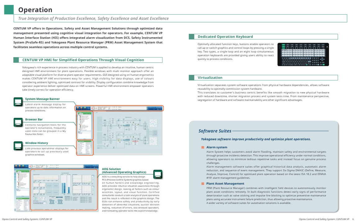
The deep integration of the three major goals of “production excellence, safety excellence, and asset excellence” is achieved through cognitive visual integration technology to optimize data presentation. For example, HIS (Human Machine Interface Station) can unify the visualization of alarm information from DCS, Safety Instrumented System (ProSafe RS), and Factory Resource Manager (PRM), breaking down barriers to multi system operation and achieving seamless collaboration.
2. Humanized Human Machine Interface (HMI)
Design concept: Based on ergonomics and experience in Yokogawa Industries, create an intuitive and easy-to-use operating environment that adapts to the usage habits of different operators
Core features:
Flexible configuration: supports multi screen display and custom window layout to meet the visualization needs of complex production scenarios
High visibility: sufficient data display brightness, color matching suitable for industrial lighting environment, contrast optimization to improve readability
Convenient navigation: including system message bar (displaying the latest alarm information in real time), browser bar (supporting common function collection and grouping), window history (quickly calling past operation interfaces)
AOG solution: Advanced Operating Graphics consulting service, where certified consultants design PCS graphics based on human factors and knowledge engineering. By optimizing color, layout, and visual functions, it achieves early anomaly detection, rapid decision-making, and reduces operational errors, while transforming operator experience into explicit knowledge
3. Specialized operation keyboard
Provide two types of dedicated keyboards, with optimized function key layout that supports one click calling of graphics or control circuits, helping operators quickly respond to process changes:
Single loop operation keyboard: suitable for precise operation of a single control loop
Simultaneous operation keyboard with eight circuits: meeting the efficient requirements of multi circuit collaborative control
4. Virtualization technology
Decoupling system software and physical hardware, improving software reusability, brings multiple advantages:
Convenient Migration: Supports smooth migration to new physical hardware, reducing downtime
Efficient testing: Shorten the system testing cycle and reduce the limitations caused by hardware dependencies
Maintenance optimization: independent maintenance of software and hardware to enhance operational flexibility
5. Core software suite
Alarm Management System: Compliant with ISA 18.2 and EEMUA # 191 standards, supporting Six Sigma DMAIC (Definition Measurement Analysis Improvement Control) method, with graphical historical data analysis, automatic alarm filtering, and event sequence management functions, effectively avoiding alarm proliferation and allowing operators to focus on core process issues
Factory Resource Manager (PRM): Linked with intelligent on-site devices, it enables remote autonomous monitoring of asset status, identifies signs of equipment performance degradation (such as valve jamming and pulse line blockage) in advance through built-in diagnostic functions, accurately predicts instrument failures, optimizes preventive maintenance plans, and achieves proactive operation and maintenance
(2) Control module: ensuring high reliability and stable operation
1. High availability design
Dual redundancy architecture: The processor module, power supply, I/O module, and I/O network of FCS (Field Control Station) all adopt a dual redundancy design, with the main and backup modules running synchronously, seamlessly switching to the backup module in case of failure, ensuring control continuity and no downtime losses
Online maintenance capability: supports online modification of FCS application logic and parameters, allows for online replacement of faulty modules without interrupting process control, and adapts to scenarios such as factory expansion and process adjustment
2. Core Control Unit (FCS)
100% independently developed and manufactured by Yokogawa, continuing the high reliability genes of the CENTUM series
Equipped with powerful processing capabilities and large capacity application storage, fully adapted to advanced on-site digital technology, ensuring efficient, safe, and stable control of the production process
3. Security Control Network (Vnet/IP)
Technical specifications: Compliant with IEEE802.3 Ethernet standard, with a transmission rate of 1Gbps, supporting both star and ring topologies
Core advantages: It combines openness and security, does not affect the efficiency of process control data transmission, and has built-in security mechanisms such as anti fraud, anti tampering, and anti DoS attacks to ensure the stability and reliability of the control network; Regardless of project size and complexity, it can ensure HIS data updates every second
N-IO (Network I/O) next-generation software can configure intelligent I/O, with a single module supporting AI/AO/DI/DO signals; The signal type of each I/O point is configured through adapter software to adapt to design changes; No need for traditional wiring grouping, saving installation space and cost; Can be deployed as a remote I/O module in on-site remote junction boxes that require flexible adaptation of signal types, pursuit of installation efficiency and cost optimization scenarios
FIO (Field Network I/O) divides various modules according to process signal types, and can be connected to field equipment through pressure clamp terminal blocks, dedicated terminal boards, or MIL cables in traditional industrial scenarios that require configuration through terminal blocks
RIO system upgrade I/O includes Remote I/O module and RIO system upgrade dedicated I/O module, maximizing the utilization of existing assets and achieving rapid system upgrade. Based on the expansion and upgrade scenarios of the existing RIO system
5. Function blocks and control capabilities
Provide rich functional blocks, covering monitoring, control, operation, calculation, logic functions, and sequence control, supporting continuous control, advanced control, complex sequence control, and batch control. The control system can be flexibly designed through the combination of functional blocks to maintain modularity and scalability
(3) Engineering module: Accelerating project delivery and quality improvement
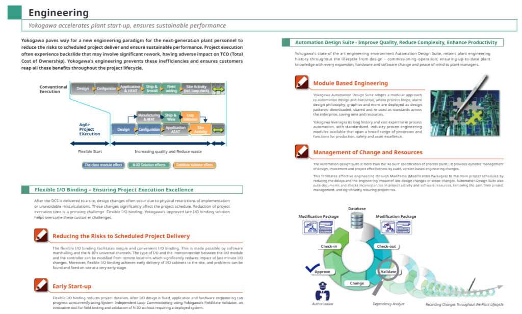
1. Core engineering environment: Automation Design Suite
Full lifecycle data management: Record the complete engineering history from design, debugging to operation, ensuring data integrity and consistency during system expansion, software and hardware changes, and providing reliable engineering archives for factory managers
Modular engineering: Encapsulate process loops, alarm design, graphics, etc. into standardized design modules that can be downloaded, shared, and reused across enterprises, reducing repetitive work and saving time and resources
Change and Resource Management: Implement version based engineering change management through ModPacks, automatically document project activities and detect data inconsistencies, reducing project delays and risks caused by later changes
2. Flexible I/O binding technology
Core advantage: Based on software grouping and N-IO universal channels, it supports remote modification of I/O types and module controller connection relationships, greatly reducing the impact of later design changes on project progress
Project Value:
Early delivery of I/O cabinets to the site, early detection and resolution of installation issues
Combined with FieldMate Validator debugging tool, it supports independent loop debugging of the system, eliminating the need to deploy a complete system and shortening project duration
Engineering design and hardware installation can be carried out in parallel to improve project execution efficiency
3. Agile project execution
Compared to traditional project processes (design configuration manufacturing and factory acceptance testing shipping installation on-site activities), CENTUM VP reduces rework and waste, improves project quality and delivery efficiency, and lowers total cost of ownership (TCO) through modular design, flexible I/O binding, and other technologies
(4) Sustainable Plant: Ensuring Long Term Value
1. Full lifecycle services
Yokogawa provides service support covering the entire lifecycle of the system, including online upgrades, patch updates, migration services, security solutions, etc. Through deep collaboration with customers, it ensures the sustainable return on investment of control system assets
2. Long term stable operation guarantee
Component updates and upgrades: By updating outdated components, replacing outdated supported peripherals, upgrading FCS (improving processing speed and adding new features), etc., seamless system transition can be achieved. Maintenance activities can be synchronized with factory downtime without taking up additional production time
Lifecycle performance assurance services: covering planning and execution, maintenance, protection, analysis, modernization upgrades, and other aspects, providing services such as engineer dispatch, workbench maintenance, equipment status monitoring, seamless upgrades, etc., to prevent unexpected failures
3. Network security protection system
Security certification: CENTUM VP on-site control unit obtained ISASecure certification ® EDSA (Embedded Device Security Assurance) certification, rigorously tested by CSSC (Control System Security Center) certified laboratory, meets the security requirements of industries such as petroleum, petrochemical, and power
Endpoint Security Services: Provides USB port locking, security information services, antivirus software, whitelist software, etc., verifies the compatibility of Yokogawa products with antivirus software, Microsoft security updates, and ensures system endpoint security
Security network design: Vnet/IP control network has multiple built-in security mechanisms to resist various network attacks, and Windows PC/Server provides security configuration options
System architecture and core components
(1) Hardware components
Component Name Abbreviation Core Function Hardware Configuration
The core interface for HIS operator control and monitoring in the human-machine interface station is based on the Windows operating system, using commercially available PC hardware, and can be optionally equipped with a dedicated operation keyboard
The ENG system configuration, programming, debugging, and maintenance of the engineering station are consistent with the HIS hardware configuration, and are equipped with the complete CENTUM VP engineering suite
The core control unit of the FCS system in the on-site control station is independently developed and manufactured by Yokogawa, with dual redundancy design, high reliability and processing capability
Unified gateway station/general subsystem gateway UGS/GSGW system interface and subsystem control UGS to achieve docking with STARDOM or third-party subsystems; GSGW is used to operate and monitor the subsystems connected to CENTUM VP
Bus converter BCV network domain connection and system compatibility connect multiple control network domains, achieving compatible docking between the previous generation CENTUM system and CENTUM VP
(2) Network and Communication Architecture
Control network: Vnet/IP (1Gbps, redundant design), responsible for real-time transmission of core control data, safe and reliable
Digital fieldbus: supports FOUNDATION ™ fieldbus、HART、PROFINET、PROFIBUS-DP、DeviceNet、Modbus、Modbus/TCP、EtherNet/IP Multiple industrial bus protocols are available to adapt to different brands and types of field devices
(3) Key software components
UACS (Unified Alarm and Status Server): Complies with IEC 62682 (Ed1, 2014)/ISA18.2-2016 standards, standardizes alarm management, and improves alarm response efficiency
Operational Excellence Software Suite: Based on the Windows platform, it covers functions such as factory security, asset operation and maintenance, production management and optimization, providing comprehensive support for efficient plant operations
Safety Control Station (SCS) – ProSafe RS: A T Ü V SIL3 certified safety instrumented system that integrates Yokogawa Pair&Spare and Vnet/IP technologies, with strong synergy with CENTUM VP
STARDOM Network Control System: Intelligent Hybrid Remote Communication Controller, suitable for the upstream oil and gas market, can be seamlessly integrated with CENTUM VP through UGS
Applicable industries and scenarios
Core industries: Process industries such as petroleum, petrochemical, power, chemical, metallurgical, pharmaceutical, water treatment, etc
Key scenarios:
Real time control and monitoring of continuous production processes
Safety protection and emergency response in high-risk industrial scenarios
Remote operation and preventive maintenance of industrial assets
Collaborative operation and data management of multi system integration
Upgrading, expanding, and migrating existing systems to third-party systems