Call us 24/7uaedcs@163.com
Welcome to the official website of CNIACS Automation Technology Co., Ltd!
Call us 24/7uaedcs@163.com

WESTINGHOUSE E510 series compact AC frequency converter

Product Overview

Product positioning: The E510 series is a compact AC frequency converter (VFD) launched by TECO Westinghouse, featuring miniaturization and easy configuration. It is suitable for motor speed control and can directly replace old VFDs, catering to various needs from simple constant speed scenarios to permanent magnet motor drives.

Core identification: Protection level IP20/NEMA 1, compliant with IEC 60018-2-78, UL, cUL, CE, RoHS certification standards.

Application scenarios: covering various motor drive scenarios such as conveyors, mixing equipment, fans, blowers, pumps, lathes, and AC contactor replacements.

Core technical parameters

Parameter category specific specifications

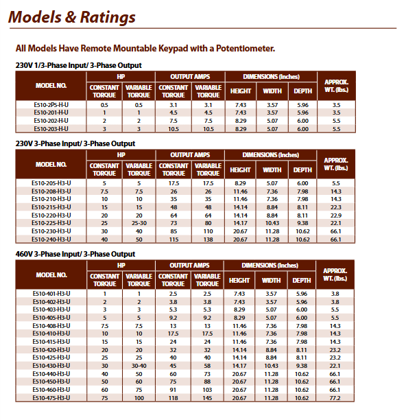
Power range 230V: 0.5-40 HP (1-phase/3-phase input); 460V: 1-75 HP (3-phase input)

Input voltage level 230V: 200-240VAC (+10%/-15%); 460V level: 380-480VAC (+10%/-15%)

Three control modes: V/Hz, sensorless vector (SLV), and permanent magnet sensorless vector (PMSLV)

Frequency Characteristics: Frequency Range: 0-599Hz; Frequency Accuracy: Digital Input 0.01Hz, Analog Input 0.1%

Speed ratio 50:1

Starting torque SLV mode: 150%/1Hz; V/Hz mode: 150%/3Hz

Overload capacity 150% rated output current/1 minute; 120% rated output current/1 minute (5/6 frame)

Carrier frequency 1-16kHz (adjustable)

Functional characteristics

(1) Control and regulation functions

Core control function:

Built in PLC function, supporting simple logic programming.

PID process control loop, including sleep mode, 0-10VDC/4-20mA feedback, and feedback loss detection.

Automatic Voltage Regulation (AVR) can stabilize the output voltage to cope with input voltage fluctuations.

Frequency and speed settings:

Adjustment methods: keyboard potentiometer, external terminal input, 0-10VDC/4-20mA signal, pulse input, up and down key adjustment.

Acceleration and deceleration configuration: 2 sets of acceleration and deceleration time (0-3600 seconds), supporting jog acceleration and deceleration settings and S-shaped slope.

V/Hz characteristics: 18 preset V/Hz curves+user-defined curves, supporting voltage (torque) increase adjustment.

Special functions: Rotating load start, sensorless vector automatic tuning, permanent magnet motor control, DC injection braking, power outage ride through.

(2) Operation and Configuration

Operation interface: 5-digit LED keyboard with speed potentiometer, supporting parameter programming, diagnostic monitoring, and adjustable display.

Parameter management: Parameters are grouped by function for convenient configuration; Support remote keyboard installation (including expansion cable).

Auto run: Supports Auto run mode.

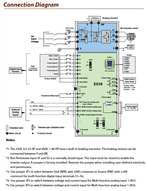
I/O and Communication Interface

(1) I/O interface specifications

Specific configuration of interface type

6-channel configurable digital input, 39 optional functions, supports normally open/normally closed settings, powered by 24V power supply, including pulse input

Digital output with 2 relay outputs, 20 optional functions, supporting normally open/normally closed settings, contact capacity of 250VAC/1A, 30VDC/1A

Analog input with 2 channels, switchable between 0-10VDC or 4-20mA, supports gain and bias adjustment, used for speed reference or PID feedback

Analog output 1 channel 0-10VDC output, 5 configurations (output frequency, set frequency, output current, etc.), supporting gain and bias adjustment

Special safety input for safety input (factory jumper short circuit), cut off the output of the frequency converter when disconnected

Power supply: Built in 24VDC power supply, maximum output current of 60mA; 10V power supply (maximum 20mA), used for external potentiometer power supply

(2) Communication function

Built in RS485 interface, supporting Modbus RTU or BACNet protocols.

Equipped with RJ45 interface and optional USB communication cable (JN5-CM-USB) for PC connection.

Protection features

Specific parameters of protection type

Overload and locked rotor protection support 150%/1-minute overload protection during acceleration, deceleration, and constant speed stages

Overcurrent protection triggered when instantaneous current exceeds 200%

Bus voltage protection overvoltage: 230V input>410VDC, 460V input>810VDC; Undervoltage: 230V input<190VDC, 460V input<380VDC

Other protective grounding faults, phase loss protection, overheating protection, PID feedback loss protection, external fault settings, fire protection mode

Environmental and physical parameters

Environmental adaptability:

Working temperature: -10~+50 ℃; Storage temperature: -20~+70 ℃.

Humidity: ≤ 95% RH (no condensation).

Vibration/impact: 20HP and below 1g (32.2ft/sec ²); 20-25HP 0.6g(19.3ft/sec²)。

Physical dimensions and weight:

230V 1/3 phase input (0.5-3HP): Size 7.43 x 3.57 x 5.96 inches, weight 3.5lbs.

460V 3-phase input (75HP): Size 20.67 × 11.28 × 10.62 inches, weight 77.2lbs.

Standardized terminal design allows for wiring without the need for specialized micro tools.

Model and accessories

(1) Core model classification

Input voltage, input phase, power range, model example

230V 1-phase/3-phase 0.5-3HP E510-2P5-H-U (0.5HP), E510-203-H-U (3HP)

230V 3-phase 5-40HP E510-205-H3-U (5HP), E510-240-H3-U (40HP)

460V 3-phase 1-75HP E510-401-H3-U (1HP), E510-475-H3-U (75HP)

(2) Optional attachments

Attachment Name Model Function

Remote keyboard extension cable JN5-CM-01M/02M/03M/05M extends keyboard installation distance

USB communication cable JN5-CM-USB connects RS485 to PC (USB interface)

LCD operation keyboard JN5-OP-A02 replaces standard LED keyboard, IP20 protection

Parameter copying unit JN5-CU uploads/downloads frequency converter parameters

NEMA 1 protective kit JN5-NK-E01~E04 enhances protection level and is compatible with 1-4 frames

Dust stickers JN5-ECOV1~ECOV4 prevent foreign objects from entering, compatible with 1-4 frames

Key issues

Question 1 (Functional Adaptability): How do the control modes and core functions of E510 frequency converters match different motor drive scenarios?

Answer: E510 provides three control modes that can be adapted to different scenarios: ① Simple constant speed scenarios (such as ordinary fans and pumps): choose V/Hz mode, paired with 18 preset V/Hz curves to meet basic speed control requirements; ② Scenarios with high requirements for starting torque and speed regulation accuracy (such as conveyors and lathes): adopting sensorless vector (SLV) mode, 150%/1Hz starting torque can cope with heavy load starting, and 50:1 speed ratio ensures operational stability; ③ Permanent magnet motor drive scenario (such as high-efficiency energy-saving equipment): Choose permanent magnet sensorless vector (PMSLV) mode, combined with automatic setting function, to fully utilize the energy-saving advantages of permanent magnet motors. At the same time, the built-in PID control can adapt to closed-loop control scenarios (such as pump equipment with pressure and flow control), and the built-in PLC function can simplify external control logic and reduce additional controller configurations.

Question 2 (Selection and Installation): How to adapt the power coverage and physical characteristics of E510 frequency converter to different installation environments, and what parameters should be focused on when selecting?

Answer: There are three key points to focus on when selecting and installing: ① Power and voltage matching: 230V level covering 0.5-40HP (1-phase/3-phase input), suitable for civilian or small industrial scenarios; 460V level covers 1-75HP (3-phase input), suitable for medium and large industrial equipment, and the corresponding model needs to be selected according to the rated power and voltage of the motor; ② Installation space adaptation: The product size ranges from 7.43 × 3.57 × 5.96 inches (low power) to 20.67 × 11.28 × 10.62 inches (high power). The miniaturized design facilitates the renovation and replacement of old equipment, and the corresponding frame size needs to be selected according to the installation space; ③ Environment and Protection: The protection level is IP20/NEMA 1, suitable for indoor dust-free environments. If protection needs to be improved, NEMA 1 kits or dust-proof stickers can be used (note that the current should not exceed 70% of the rated value after sticker installation). At the same time, it must meet the environmental requirements of working temperature -10~+50 ℃ and humidity ≤ 95% RH (no condensation).

Question 3 (Expansion and Maintenance): How do the I/O interfaces, communication functions, and accessories of the E510 frequency converter support system integration and post maintenance?

Answer: ① I/O expansion: 6 configurable digital inputs (39 functions), 2 relay outputs (20 functions), and 2 analog inputs/outputs, which can flexibly interface with external devices such as sensors, actuators, buttons, etc., to meet complex control logic requirements; ② Communication integration: Built in RS485 interface (Modbus RTU/BACNet), supports communication with upper computers such as PLC and touch screen, optional USB cable for PC parameter configuration, facilitating centralized system control; ③ Maintenance convenience: equipped with LED keyboard (supports remote installation), can directly program parameters and diagnose faults; Optional LCD keyboard and parameter copying unit, simplifying the unified configuration of parameters for multiple devices; The NEMA 1 kit and dust stickers are standard accessories for easy replacement and maintenance in the future, ensuring long-term stable operation of the equipment.

WESTINGHOUSE E-Series MCCB (Molded Case Circuit Breaker)

Product Overview and Brand Background

Brand foundation: As a globally renowned brand with a 130 year history of product innovation, Westinghouse’s business covers areas such as home appliances, consumer electronics, power generation and distribution equipment, with reliability and innovation as its core advantages.

Product positioning: The E-series molded case circuit breaker (MCCB) is the core product in its power transmission and distribution field, designed specifically for industrial and civilian power distribution systems. Its core function is to achieve overload protection and short circuit protection of the circuit, ensuring the safety of electrical equipment and lines.

Core standard: The product fully complies with the IEC 60947-2 international standard, has passed CE certification, has stable performance, and has extensive compatibility.

Overview of Core Technical Parameters

Parameter category specific specifications

Rated current range 16-800A (subdivided by frame size: EJ: 100-250A; EK:320-630A)

Rated voltage 240/415V AC (operating voltage); Ui (insulation voltage) up to 1000V; Uimp (impulse withstand voltage) 8-12 kV

Short circuit breaking capacity (Icu/Ics) 25kA, 36kA, 50kA, 85kA (different series correspond to different breaking levels)

Frequency adaptation 50/60Hz

Pole configuration with 3 or 4 poles (both configurations are supported across the entire series)

Calibration temperature 55 ℃ (rated current based on this temperature calibration)

Wiring specifications: Cable cross-section 25-300mm ² (adapted according to different frame sizes)

Certification Mark CE Certification

Product series segmentation and model details

The product is divided into two main frames and multiple sub series based on frame size and short-circuit breaking capacity. Each sub series includes different types of trip and pole combinations, as follows:

(1) EJ framework (rated current 100-250A)

Core features: Compact size, suitable for low and medium current scenarios, with a breaking capacity covering 25-50kA, supporting both automatic and non automatic operation modes.

Subseries and Model Details:

Subseries short circuit breaking capacity, trip type, pole number, rated current specification, reference number example

EIJ 25kA fixed thermal magnetic release (F) 3P/4P 100A, 125A, 160A, 200A, 250A EIJ3100F (W605836), EIJ4100F (W605841)

EIJ 25kA Adjustable Thermomagnetic Release (TM) 3P/4P 100A, 125A, 160A, 200A, 250A EIJ3100TM (W605846), EIJ4100TM (W605851)

ESJ 36kA Adjustable Thermomagnetic Release (TM) 3P/4P 100A, 125A, 160A, 200A, 250A ESJ3100TM (W605856), ESJ4100TM (W605861)

EHJ 50kA Adjustable Thermal Magnetic Release (TM) 3P/4P 100A, 125A, 160A, 200A, 250A EHJ3100TM (W605866), EHJ4100TM (W605871)

EIJY – Non Automatic 3P/4P 100A, 125A, 160A, 200A, 250A EIJY3100 (W605876), EIJY4100 (W605881)

Physical dimensions and weight:

3 poles: height 165mm x width 105mm x depth 77mm, weight 1.5kg

4-pole: height 140mm x width 185mm x depth 77mm, weight 2.0kg

(2) EK frame (rated current 320-630A)

Core features: Suitable for medium and high current scenarios, with a breaking capacity covering 36-50kA, some models support electronic tripping, and higher adjustment accuracy.

Subseries and Model Details:

Subseries short circuit breaking capacity, trip type, pole number, rated current specification, reference number example

ESK 36kA fixed thermal magnetic release (F) 3P/4P 320A, 400A, 500A, 630A ESK3320F (W605886), ESK4500F (W605904)

ESK 36kA Adjustable Thermomagnetic Release (TM) 3P/4P 320A, 400A, 500A, 630A ESK3320TM (W605890), ESK4630TM (W605909)

ESK 36kA Electronic Release (E) 3P/4P 500A, 630A ESK3500E (W607452), ESK4630E (W610439)

EHK 50kA Adjustable Thermal Magnetic Release (TM) 3P/4P 320A, 400A, 500A, 630A EHK3320TM (W605894), EHK4630TM (W605913)

EHK 50kA Electronic Release (E) 3P/4P 500A, 630A EHK3500E (W607454), EHK4630E (W610441)

ESKY – Non Automatic 3P/4P 320A, 400A, 500A, 630A ESKY3320 (W605898), ESKY4630 (W605917)

Physical dimensions and weight:

3 poles: height 257mm x width 140mm x depth 111.7mm, weight 5.7kg

4-pole: height 257mm x width 185mm x depth 111.7mm, weight 7.5kg

Types and characteristics of trip units

The trip unit is the core component of a circuit breaker, responsible for detecting circuit abnormalities and triggering tripping. The E series offers three types to meet different precision requirements:

Fixed Thermal&Magnetic Release

Working principle: The parameters of thermal trip (overload protection) and magnetic trip (short circuit protection) are fixed and do not require manual adjustment, making operation simple.

Applicable scenarios: General scenarios without special adjustment requirements for protection parameters.

Adjustable Thermal&Magnetic Release

Hot release adjustment range: 0.8-1.0In (suitable for different overload current thresholds)

Magnetic release adjustment range: 5-10In (suitable for different short-circuit current thresholds)

Applicable scenarios: Scenarios that require flexible adjustment of protection parameters based on circuit load characteristics, with stronger universality.

Electronic Adjustable Release

Core advantages: Higher adjustment accuracy, more stable protection characteristics, only available in EK frame 500-630A models.

Applicable scenarios: Industrial equipment and precision distribution systems that require high protection accuracy.

Accessories and Installation Configuration

Optional attachments: Supports shunt trip, under voltage trip, auxiliary contacts, trip alarm contacts, and can expand the control and signal feedback functions of the circuit breaker.

Wiring method: Cable wiring is used, supporting both incoming (Line) and outgoing (Load) lines, suitable for cables with cross-sections of 25-300mm ², and meeting different current carrying requirements.

Installation adaptation: The product structure design is suitable for various installation scenarios such as industrial distribution cabinets and civilian distribution boxes, with standardized physical dimensions and strong interchangeability.

Time current characteristics

Circuit breakers of different current levels have clear time current curves to ensure the accuracy of protection actions:

Overload protection (delayed tripping): The closer the current is to the overload threshold, the longer the tripping time (such as the 200-250A model, when overloaded with 1.3 times the rated current, the tripping time is about 10-30 minutes).

Short circuit protection (instantaneous trip): When the short-circuit current reaches the magnetic trip threshold, it will trip instantly (maximum total break time ≤ 0.05 seconds) and quickly cut off the faulty circuit.

WESTINGHOUSE Transformer Product Line

Brand and Quality Assurance

Brand Background: Westinghouse was founded in 1886 and has a 130 year history of product innovation. It is a globally trusted industrial and consumer product brand, with business covering multiple fields such as home appliances, consumer electronics, lighting, and power generation equipment.

Quality standards: The product strictly follows IEC international standards and Chinese GB standards, and some products can be designed and produced according to customized user needs.

Certification qualifications: Through ISO9001, ISO14001, OHSAS18001 system certification, transformer products have obtained authoritative certifications from KEMA in the Netherlands and CTQC (National Transformer Quality Supervision and Inspection Center) in China, covering products with different capacity levels of 16MVA-180MVA.

Transformer product system and core parameters

Westinghouse Transformer has a rich product line, covering 16 core products, which can be divided into the following categories according to voltage levels and applications. The key parameters are shown in the table below:

Product Category Voltage Level Rated Capacity Range Core Features Typical Parameter Examples

Power transformers with 220kV, 110/66kV, 35kV, 31500kVA-420000kVA dual winding/triple winding, on/off excitation voltage regulation, oil immersed short-circuit impedance of 6% -34%, no-load loss of 32kW-173kW

Distribution transformers 20kV, 10kV 30kVA-2500kVA have small size, light weight, low loss short-circuit impedance of 4% -6%, and no-load loss of 100W-3960W

Amorphous alloy core distribution transformer 10kV 30kVA-2000kVA is energy-saving and efficient, with no-load loss 50% lower than traditional products, no-load loss 33W-750W, and short-circuit impedance 4% -5%

Dry type transformer 35kV, 10kV 30kVA-25000kVA resin casting, low partial discharge (≤ 5PC), suitable for indoor no-load loss of 190W-27100W, short-circuit impedance of 4% -10%

Special purpose transformer -500kVA-10000kVA designed for specific scenarios, suitable for rectifier transformers with voltages ranging from 10kV to 66kV; Furnace Transformer: Suitable for Metallurgical/Chemical Smelting

Voltage regulating transformers ranging from 2.5kV to 35kV are matched with on load voltage regulation and automatic voltage regulation as needed, with 7-16 steps and a mechanical lifespan of 1 million cycles

Key product classification

power transformer

Covering three core voltage levels of 220kV, 110/66kV, and 35kV, including dual winding, triple winding, and self coupling structures.

Supports on load voltage regulation (OLTC) and non excited voltage regulation (NLTC), with a rated capacity of up to 420000kVA, meeting the high-voltage transmission needs of power plants and large substations.

Typical parameters: 220kV double winding transformer with no-load loss of 32kW-173kW, load loss of 128kW-824kW, and short-circuit impedance of 6% -14%.

distribution transformer

The voltage levels include 20kV and 10kV, with a rated capacity of 30kVA-2500kVA, suitable for distribution scenarios in residential communities, commercial centers, and small and medium-sized enterprises.

The 10kV distribution transformer adopts advanced core lamination technology, with no-load loss of 100W-1960W and load loss of 600W-18000W, low noise, and maintenance free.

Special purpose transformer

Rectifying Transformer: Suitable for scenarios such as electrochemical electrolysis, direct current transmission, and industrial rectification, with a rated power of 800kV-16000kV and a voltage of 6kV-35kV.

Furnace transformer: designed specifically for the metallurgical and chemical industries, used for alloy steel and ferroalloy melting, as well as yellow phosphorus and calcium carbide production. It has a rated capacity of 650kVA-25000kVA and supports overload operation.

Photovoltaic integrated substation: integrating inverters and boosting stations to increase the DC voltage of photovoltaic panels to 11kV/33kV AC voltage, with a maximum output of 3000kW per station.

Other types

Dry type transformer: indoor installation, resin casting process, partial discharge ≤ 5PC, suitable for high cleanliness scenarios, capacity 30kVA-25000kVA.

Column mounted transformer/box type transformer: compact structure, flexible installation, suitable for urban and rural distribution networks, road lighting, with a capacity of 30kVA-2500kVA.

Fully Automatic Protection Transformer (CSP): Integrated with high voltage fuses, low voltage circuit breakers, and lightning protection devices, it has short-circuit, overload, and lightning protection functions.

Operating environment and installation requirements

Temperature conditions: The working temperature of most products is -30 ℃ to+40 ℃, while some products such as dry-type transformers and column mounted transformers have a working temperature of -5 ℃ to+40 ℃, and a storage temperature of -40 ℃ to+70 ℃.

Altitude limit: The default installation altitude is ≤ 1000m, and if it exceeds this altitude, parameters such as temperature rise need to be corrected.

Humidity requirement: The working humidity should be ≤ 90% RH (without condensation) to avoid damage to the product caused by moisture inside.

Installation environment: It should be installed in a location free from corrosive gases, severe pollution, and severe vibrations and impacts. Outdoor products should have windproof and rainproof capabilities.

Application scenarios

Industrial scenarios: power distribution and production equipment power supply for steel plants, chemical plants, metallurgical plants, calcium carbide plants, and large manufacturing plants.

Energy scenarios: Energy conversion and transmission in power plants, substations, distribution networks, photovoltaic power stations, and wind power supporting facilities.

Livelihood scenarios: daily power distribution in residential communities, commercial centers, high-rise buildings, urban and rural buildings, schools, and hospitals.

Key issue

Question 1 (Product Adaptability): What is the voltage level and capacity coverage range of Westinghouse transformers, and what core scenarios can they meet for electricity demand?

Answer: The voltage level of Westinghouse transformers covers 2.5kV-220kV, with a rated capacity range of 30kVA-420000kVA, covering 16 core products. Low voltage level (10kV-35kV) and small capacity (30kVA-2500kVA) distribution transformers/dry-type transformers can meet the daily power distribution needs of residential communities, commercial centers, and small and medium-sized enterprises; Medium to high voltage level (110kV-220kV) and large capacity (31500kVA-420000kVA) power transformers, suitable for the high-voltage transmission needs of power plants and large substations; Special purpose transformers (rectifier, furnace, photovoltaic integration) can meet the specialized electricity needs of industries such as metallurgy, chemical, and new energy generation.

Question 2 (Quality and Reliability): What authoritative certifications have Westinghouse transformers passed, and how do their core technological advantages ensure operational reliability?

Answer: In terms of quality certification, our products have passed ISO9001/ISO14001/OHSAS18001 system certification, and our transformer products have obtained authoritative certifications from KEMA in the Netherlands and CTQC in China. They comply with IEC and GB standards in China, and some can be customized for production. In terms of technological advantages, firstly, the optimized design of the iron core, coil, and oil tank structure is adopted to achieve low loss (minimum no-load loss of 33W), low noise, and small volume characteristics; Secondly, key products have comprehensive protection functions, such as CSP series transformers integrated with high-voltage fuses, low-voltage circuit breakers, lightning protection devices, and furnace transformers supporting overload operation; The third is to adopt advanced production processes (such as resin casting and core lamination optimization), combined with strict factory inspections, to ensure long-term stable operation. The short-circuit impedance is controlled at 3.5% -34%, suitable for different power grid conditions.

Question 3 (Installation and Customization): What are the installation environment requirements for Westinghouse transformers, is personalized customization supported, and what is the scope of customization?

Answer: The installation environment requirements include: altitude ≤ 1000m (adjustable parameters beyond altitude), working temperature -30 ℃ to+40 ℃ (some products -5 ℃ to+40 ℃), humidity ≤ 90% RH (no condensation), and the installation site must be free of corrosive gases, severe pollution, and severe vibration. The product supports comprehensive personalized customization, including voltage level and transformation ratio, rated capacity and short-circuit impedance, winding structure (double winding/three winding), voltage regulation method (on load/off excitation), cooling method (oil immersed/dry/forced air cooling), protective accessories (fuses, circuit breakers, lightning protection devices), cabinet size, material, etc., which can accurately match the specific scene needs of users.

Emerson Ovation OCR1100 Controller

Product Overview

System: Emerson Ovation Distributed Control System (DCS) is the core control unit of the system, designed specifically for critical task scenarios such as power generation and water supply and drainage plants that require high reliability.

Core positioning: Execute simple/complex adjustment and sequential control strategies, complete core functions such as data acquisition, I/O interface adaptation, event processing, etc., to ensure the precise operation of industrial processes.

Key certifications: IEC 61131-3 standard compliance (Unified Programming Configuration Mechanism), Achilles Level 1 certification (Industrial Equipment Network Robustness Certification).

Core functional parameters

Specific details of key information for functional categories

Control task capability: Control a maximum of 5 tasks, which can be executed simultaneously

Cycle speed range Ovation 3.6 and below: 2 pre-defined (1 second, 100 milliseconds)+3 user-defined; Ovation 3.7 and above: all 5 user-defined, ranging from 10 milliseconds to 300 seconds (increasing by 10 milliseconds)

The highest number of origin points for data processing capability is 32000

Event sequence resolution of 1 millisecond, recording the sequence of digital input state changes

Redundancy and Fault Switching Redundancy Components Network interfaces, processors, power supplies, I/O interfaces, and other key component redundancies

Switching feature: automatic fault switching, achieving bumpless switching, supporting automatic recovery of backup roles after fault repair

Alarm processing threshold types: 6 independent alarm thresholds (4 high limits+4 low limits, including user-defined and incremental thresholds)

The processing logic is defined according to the process point database, supporting single node alarm delay, and the workstation can display in order of importance

Hardware and Architecture Characteristics

Core hardware parameters:

Processor: Intel based, base frequency 1.1 GHz

Storage configuration: 1 Gb Flash+256 Mb RAM

Network interface: 4 10/100 Mb Ethernet ports, two options: ① 4 x RJ45; ② 1 x RJ45+3 x SFP fiber optic

Power supply requirement: 24 VDC 40W

Physical dimensions: 20 “wide x 8” high x 7 “deep

Environmental adaptability: Operating temperature 0-60 ℃ (4 x RJ45)/0-50 ℃ (fiber optic option), humidity 0-95% RH (non condensing)

Architectural features:

Open architecture: using CompactPCI ®  I-bus PC design, supporting technology upgrades and software investment protection

Operating System: Multi tasking real-time operating system, communicating through TCP/IP protocol, supporting resource management and routing functions

Hardware compatibility: Shared packaging design with the previous generation OCR400, supports backward compatibility, can upgrade old model control logic and database through migration program (requires Ovation 3.5 and above system support)

I/O compatibility and scalability

I/O Type Support Specification Remarks

Local Ovation I/O can have up to 16 independent branches, with 8 modules per branch, for a total of 128 I/O modules

Local Q-Line I/O 1 node, containing 48 Q-Line I/O cards

Expand Q-Line I/O with an additional node, including 48 Q-Line I/O cards, supporting only one type of expansion I/O at a time

Remote node interface can support up to 16 remote node interface modules, each supporting 64 I/O modules

Remote Ovation I/O supports up to 8 nodes, with each node supporting 64 I/O modules. Only one remote I/O type is supported at a time

Remote Q-Line I/O can have up to 8 nodes, each containing 48 Q-Line I/O cards. Only one remote I/O type is supported at a time

Intelligent devices are compatible with Foundation fieldbus PROFIBUS、DeviceNet 

Virtual I/O (Ethernet protocol) Allen Bradley PLCs, Modbus/TCP, GE Mark V/VI, etc. are compatible with third-party OEM systems

Deployment and Cabinet Configuration

Installation method: DIN rail installation, which can flexibly adapt to different sites, environments, and space requirements

Cabinet type:

|Cabinet type | Size (h × w × d) | Weight (full configuration) | Capacity | Operating temperature|

|Standard Controller Cabinet | 79 x 24 x 24 inches (2006.6 x 609.6 x 609.6mm) | 426.25 lbs (191.81kg) | Redundant Controller, 32 I/O Modules, 2 Power Supplies | Same NIC Port Requirements (0-50 ℃/0-40 ℃)|

|Expansion cabinet | 79 x 24 x 24 inches (2006.6 x 609.6 x 609.6mm) | 396.25 lbs (178.31kg) | Backup equipment, 32 I/O modules, 2 power supplies | 0-60 ℃|

Customization options: Support OEM customization such as front-end single access, special size/material, and environmental grade adaptation

BENDER Isolated Power Panels

Product Overview

BENDER isolated power panel is a safe power supply solution designed for critical medical areas. The core goal is to achieve equipotential power supply through isolation transformers and precise monitoring technology, avoiding the risk of electric shock caused by grounding faults. The product is divided into three categories: standard type, dual output voltage type, and dual system type. It can expand sockets, grounding components, and fault location systems according to the needs of medical scenarios, and is equipped with communication gateways and remote indicators to form a “power supply monitoring positioning monitoring” full chain safety system. It strictly follows the electrical standards of the medical industry and is suitable for scenarios such as operating rooms and intensive care units that require extremely high reliability and safety of power supply.

Comparison of core models and configurations

Model Series Core Features Power Range Voltage Output Key Configuration Applicable Scenarios

Standard Type (IP) Single Isolation System 3kVA~25kVA Single Voltage (120V/208V/240V, etc.) 1 LIM2010, 8-way Branch Circuit Breaker (expandable 16 ways) General Intensive Care Unit, Diagnosis and Treatment Room

Dual output voltage type (ID) single transformer dual secondary 25kVA 120V+208V/240V 2 LIM2010, dual grounding bars, independent branch circuits with limited space and multiple voltage scenarios required

Dual system type (IX) with two independent isolation systems, each with a voltage output of 3kVA~10kVA. Each system has two independent voltage outputs, including two isolation transformers and two LIM2010 operating rooms with high reliability requirements

Core component specifications

(1) Isolation transformer

Power specifications support voltage (primary/secondary) adaptation model series

3kVA/5kVA 120V~480V/120V~240V IP series

7.5kVA/10kVA 120V~480V/120V~240V IP/IX series

15kVA/25kVA 120V~480V/120V~240V IP/ID series

(2) LIM2010 Line Isolation Monitor

Display mode: digital+analog dual display

Response value options: 2mA, 5mA

Alarm function: overvoltage/undervoltage, overload, overheating, grounding fault

Core features: self checking and self calibration, support for EDS fault location expansion

Communication interface: compatible with RS-485, can be connected to centralized monitoring system

(3) Fault location system (EDS461 series)

Module model, display type, output interface, core parameters

EDS461-D LCD displays 1 DPDT contact supporting 12 current transformers, RS-485 interconnection

EDS461-L LED indicates 1 DPDT contact supporting 12 current transformers, RS-485 interconnection

Scalability: up to 90 EDS modules interconnected, supporting 708 sub loop monitoring

Positioning method: Receive LIM2010 test pulses and identify faulty circuits through current transformers

Installation and Extension Options

(1) Installation method and size

Installation type, bottom box material, size example (height x width x depth), compatible model

Embedded 14GA galvanized steel 43 “× 24” × 6 “(3/5kVA) IP/ID/IX series

Surface mounted 14GA galvanized steel (ivory white baked paint) 43 “× 24” × 6 “(3/5kVA) IP/ID/IX series

Panel Material: 14GA 304 Stainless Steel (# 4 brushed) Embedded Panel 1 “Larger than Bottom Box, Full Series

(2) Extension function options

Distribution Expansion:

Circuit breaker types: Plug On (Square D/Cutler Hammer/GE), Bolt On

Current specifications: 20A/30A/50A/60A, supports 2P configuration

Socket and grounding:

Socket type: direct insertion single/double (red/ivory white), twist lock type (black)

Grounding components: Hospital grade grounding socket, HGC series grounding cable (10/12/15 feet)

Control extension:

PLC control module: supports 12 channels of X-ray/laser equipment power supply, including threshold switch and “in use” indicator light

Load monitoring: STW series current transformers achieve transformer overload monitoring

Communication and Remote Monitoring

(1) Communication gateway

Model Communication Protocol Core Functions

COM460IP Ethernet, Modbus/TCP web monitoring, email/SMS alarm, remote access

FTC470XMB Modbus/RTU connects 10 BENDER devices and integrates them into the building management system

FTC470XDP Profibus/DP is compatible with industrial bus systems and supports device control

(2) Remote indicator

Series Core Features Featured Models

MK2000 sound and light alarm, mute function MK2000CBM (with digital display and overload indication)

MK2430/MK800 LCD displays fault location and testing function MK2430-11 (12 channel digital input)

RAS series multi-channel centralized indicator RAS-04B (integrated with 4 indicators)

Key issues

Question 1: What are the core differences among the three core models of BENDER isolated power panels (standard type, dual output voltage type, dual system type)? How to choose based on the scenario?

Answer: The core differences are concentrated in the power supply system architecture and voltage output capability. The selection logic is as follows: ① Standard type (IP series): single isolation system+single voltage output, power 3kVA~25kVA, suitable for most intensive care units, diagnosis and treatment rooms and other single voltage demand scenarios; ② Dual output voltage type (ID series): single 25kVA transformer+dual secondary winding, simultaneously outputting 120V and 208/240V, equipped with dual LIM2010 monitors, suitable for space limited scenarios that require power supply for both ordinary medical equipment (120V) and high-power equipment (208/240V); ③ Dual system type (IX series): Two independent isolation systems, each equipped with transformers and monitors, supporting seamless switching in case of faults, suitable for critical scenarios such as operating rooms that require extremely high power supply reliability.

Question 2: What is the core function of LIM2010 line isolation monitor? How to quickly locate grounding faults?

Answer: The core function of LIM2010 is: ① Real time monitoring of the insulation status of the isolated power supply system, supporting 2mA/5mA response value setting, with digital and analog display; ② Equipped with self checking and self calibration functions, it can monitor faults such as overvoltage, undervoltage, overload, and overheating and trigger sound and light alarms; ③ Support linkage with EDS461 series fault location module. Rapid positioning process for grounding faults: ① LIM2010 triggers an alarm after detecting a grounding fault; ② EDS461 module automatically activates and receives test pulses sent by LIM2010; ③ The current transformers distributed in each branch circuit capture pulse signals; ④ EDS461 analyzes signals through RS-485 interconnection and displays the fault circuit location on LCD/LED; ⑤ Remote indicator synchronous alarm, supporting up to 708 sub loop monitoring.

Question 3: What are the expansion capabilities of BENDER isolated power panels reflected in? How to achieve centralized management of communication monitoring system?

Answer: The expansion capability is mainly reflected in three aspects: ① Distribution expansion: Standard 8-way branch circuit breakers can be expanded to 16 ways, supporting Plug On/Bolt On two types, with current specifications covering 20A-60A; ② Function extension: Can add hospital level sockets, grounding sockets, PLC control modules (up to 12 device controls), EDS461 fault location system; ③ Monitoring Expansion: Supports MK series remote indicators and sound and light alarms, and connects to a communication gateway for centralized management. Centralized communication management method: ① Hardware level: Connect all devices through COM460IP (Ethernet/Modbus/TCP) or FTC470XMB (Modbus/RTU) gateway; ② Functional aspect: Real time viewing of device status and fault location on the web page, supporting email/SMS alarm push; ③ System integration: Compatible with OPC servers and SCADA/BMS building management systems, achieving unified monitoring of medical area power supply systems.

Bender LifeGuard® LG2-Series Protection Panels

Product Overview

Bender LifeGuard ®  The LG2 series is an industrial grade ground fault protection panel launched by Bender. Its core mission is to monitor the ground fault current in the circuit in real time, and quickly cut off the load power supply when the current reaches the preset trip threshold, avoiding safety risks such as electric shock and arc flashover. The product is suitable for industrial circuits with multiple voltages and phases, providing flexible installation forms and trip level selection. It strictly follows the UL 508A industrial control panel standard and is widely used in factory equipment, industrial control systems, and other scenarios that require extremely high electrical safety.

Core parameters and specifications

Category specific parameters

Adaptation voltage  120VAC、208VAC、208/120VAC、240/120VAC、480VAC、480/277VAC、600VAC、600/347VAC

Circuit phase 1ph (2w/3w), 3ph (3w/4w)

Rated current < 100A, 100A

Release level F: Fixed 6mA; Level A: Adjustable on-site (default 30mA)

Shell type NEMA 4X polycarbonate, NEMA 4X stainless steel, backplate only (requires self provided cabinet)

Dimensions (length × width × depth) < 100A: 305 × 254 × 152mm (12 “× 10” × 6 “); 100A: 406 × 356 × 203mm (16” × 14 “× 8”)

The wire requirement is only copper wire; <100A requires ≥ 60 ℃ (140 ℉) rating; 100A needs to be rated at ≥ 75 ℃ (167 ℉)

Installation and wiring specifications

(1) Installation requirements

Installation of shell:

NEMA 4X polycarbonate/stainless steel casing with wall mounting feet, separate wall mounting instructions must be followed;

It is recommended to use NEMA 4X or higher grade connectors at the bottom of the casing for cable perforation to maintain the protection level.

Only for backplate installation:

It needs to be installed in a compliant cabinet, with vertical clearance requirements of 152mm (6 “) for<100A and 203mm (8”) for 100A;

Fix with 4 # 10 screws, with a mounting hole diameter of 6.4mm (1/4 “).

(2) Wiring rules

Installation must be carried out by licensed electricians, following local, state, and national electrical regulations;

All active conductors (including neutral wire N) need to pass through a current transformer and be connected to the incoming side of the contactor;

Connect the load or protected branch to the outgoing side of the contactor;

The incoming and load grounding wires must be connected to the backplane grounding terminal and must not pass through the current transformer;

The number of conductors and wiring diagrams corresponding to different voltages are as follows:

Reference wiring diagram for voltage specification, number of conductors (excluding grounding)

120 VAC 1ph/2w(L1、N) Figure W1

208 VAC 3ph/3w(L1、L2、L3) Figure W2

208/120 VAC 3ph/4w(L1、L2、L3、N) Figure W3

240/120 VAC 1ph/3w(L1、L2、N) Figure W4

480 VAC 3ph/3w(L1、L2、L3) Figure W2

480/277 VAC 3ph/4w(L1、L2、L3、N) Figure W3

600 VAC 3ph/3w(L1、L2、L3) Figure W2

600/347 VAC 3ph/4w(L1、L2、L3、N) Figure W3

Core functions and operating procedures

(1) Release level and range adjustment

Release level, release current adjustment method, current sensor range setting (potentiometer)

F-class fixed 6mA non adjustable —

A-level on-site adjustable (default 30mA) potentiometer adjustment CTUB101-CTBC35P ≤ 100mA: left position (8 o’clock direction); >100mA: median (12 o’clock direction)

(2) Basic operations

Power on: Close the circuit breaker/isolation switch on the incoming side, and the green POWER ON LED will light up when there is no ground fault;

Test (F level, fixed 6mA):

Press and hold the TEST button for ≥ 2 seconds, the device will trip, the red CIRCUIT TRIPPED LED will light up, and the load will be powered off;

After internal self check for about 10 seconds, press and hold the RESET button for ≥ 1 second to reset the device and restore power supply;

Test (Grade A, adjustable on site):

Press and hold the TEST button for ≥ 2 seconds, the device will trip, and the red LED will light up;

Press and hold the RESET button for at least 1 second to reset the device and restore power supply;

Range adjustment (Class A only):

Adjust the potentiometer according to the trip setting of RCMA420-D-2, with the corresponding range as follows:

Release current range, effective value measurement range, peak measurement range

I∆n ≤0.1A 0~450mA 0~900mA

0.1A<I∆n ≤0.5A 0~0.75A 0~3.5A

Safety and Compliance

Before installation, all power sources must be disconnected to avoid the risk of electric shock and arc flashover;

Separate isolation switches, branch protections, and/or overload relays need to be configured;

The three-phase three wire system can adopt direct grounding or resistance grounding methods;

Equipment troubleshooting and parameter adjustment should refer to the technical manual for protective relays (available online).

Bender LINETRAXX ® CTAC series

​Product Overview

Bender LINETRAXX ®  The CTAC series is a high-sensitivity transformer designed specifically for AC current monitoring. Its core function is to convert AC current into an assessable electrical signal, compatible with Bender’s residual current monitoring system (RCM/RCMS series) and IT system insulation fault location system (EDS series). It is widely used for current status monitoring and fault diagnosis of industrial electrical equipment. The product is divided into standard and EDS specific types, providing multiple inner diameter specifications to adapt to different cable sizes, strictly following the IEC 60664-1 standard, with reliable protection performance and installation flexibility.

Core models and compatible devices

Model type, specific model, inner diameter, compatible equipment, product number

Standard CTAC20 20mm RCM420, RCMS460/490, EDS440/460/490 B98110005

Standard CTAC35 35mm RCM420, RCMS460/490, EDS440/460/490 B98110007

Standard CTAC60 60mm RCM420, RCMS460/490, EDS440/460/490 B98110017

Standard CTAC120 120mm RCM420, RCMS460/490, EDS440/460/490 B98110019

Standard CTAC210 210mm RCM420, RCMS460/490, EDS440/460/490 B98110020

EDS specific CTAC20/01 20mm EDS441, EDS461/491 B98110006

EDS specific CTAC35/01 35mm EDS441, EDS461/491 B98110008

Key technical parameters

Category Standard Type (CTAC20/35/60/120/210) EDS Specific Type (CTAC20/35/01)

Rated conversion ratio 600/1 8000/1

Rated continuous thermal current 125A 6A

Rated short-time thermal current (1s) 2.4kA 0.36kA

Rated dynamic current (40ms) 6.0kA 0.9kA

Frequency range 15Hz~100kHz 15Hz~100kHz

Rated insulation voltage 800V 800V

Overvoltage category III III

Rated impulse voltage/pollution level 8kV/3 8kV/3

Protection level (internal/terminal) IP40/IP20 IP40/IP20

Flame retardant grade UL94 V-0 UL94 V-0

Size and weight

Model length a (mm) width b (mm) height c (mm) inner diameter d (mm) weight (g)

CTAC20(/01) 75 82 37 20 160

CTAC35(/01) 94 100 47 35 220

CTAC60 126 137 57 60 460

CTAC120 188 211 96 120 1140

CTAC210 302 324 153 210 2340

Tolerance ± 0.5mm ± 0.5mm ± 0.5mm ± 0.5mm-

Installation and wiring specifications

(1) Installation requirements

All current carrying cables must pass through the center of the transformer together, and it is strictly prohibited to pass the protective conductor through the core;

Do not pass shielded cables through transformers, otherwise it will affect measurement accuracy;

A conductor bending must maintain a minimum distance (90 ° angle distance=2 x outer diameter of the transformer) and be aligned with the center of the transformer;

Fixing method: Use M5 screws for CTAC20 (/01)/35 (/01)/60 and M6 screws for CTAC120/210, with tightening torques of 0.6Nm and 1Nm respectively.

(2) Wiring specifications

Wire requirements: rigid/flexible wire (0.2~2.5mm ², AWG24~12), with a stripping length of 7mm;

Cable length: Single stranded wire (≥ 0.75mm ²) up to 1m, twisted wire (≥ 0.75mm ²) up to 10m, shielded cable (≥ 0.5mm ²) up to 40m;

Recommended shielded cable model: J-Y (St) Y min. 2×0.8, RCM system requires one end to be connected to an L conductor (not grounded), EDS system requires one end to be connected to PE;

Terminal type: The standard type is screw terminal, while the MIL variant is push wire terminal (Phoenix Contact brand).

Accessories and Delivery

Supporting accessories: CTAC20 (/01) snap on installation part (B91080111), CTAC35 (/01) snap on installation part (B91080112);

Delivery includes: transformer body, corresponding PCB connector (MIL variant);

Customization options: B781100xxMIL variant models can be ordered as needed.

Bender GPM series grounding power module

Product Overview

The Bender GPM series is a hospital grade grounding and power integration module tailored for medical facilities, with the core goal of providing safe power supply and equipotential grounding solutions for portable medical devices. The product strictly follows the electrical standards of the medical industry, adopts high durability materials and safety design, and can flexibly adapt to different installation scenarios. It is widely used in hospitals, general diagnosis and treatment areas, intensive care units and other environments with extremely high electrical safety requirements. At the same time, it provides supporting grounding cables and sockets to form a complete medical electrical safety guarantee system.

Core configuration and specifications

(1) Module type and installation mode

Module type installation method adapted to the core characteristics of the bottom box/panel

GPM-F embedded 12 “× 8” × 4 “galvanized steel bottom box panel 14” × 10 “, extending 1” to cover the edge of the bottom box

GPM-S surface installation customized front trim panel+bottom box panel size consistent with the bottom box

GPM-G type combination panel installation, 4-pin/8-pin standard electrical junction box, single pin can accommodate 1 socket or 1 grounding socket

(2) Core component specifications

power socket

Specification: 20A/125V, hospital level certified

Types: SR/SI, DR/DI, TB

Color: Red (DR/TB), Ivory White (DI/SI)

Grounding components

Grounding socket: 30A/250V, green, twist lock design

Grounding Bar: Copper, size 0.125in (3mm) x 0.75in (19mm), supports # 14-1/0 AWG wires

Connection points: At least 20, including 18 # 14- # 6 AWG terminal blocks and 1 # 12-1/0 AWG terminal block

Grounding cable (HGC series)

Length: 10 feet, 12 feet, 15 feet

Wire specification: # 10 AWG, green PVC insulation layer, high flexibility design

Terminal Type: Plug+Heavy duty Alligator Claw (Type C), Plug+# 10 Wire Clip (Type L)

Typical models and configurations

Model configuration description Product number

GPM-F4DR4 4 grounding sockets+4 red dual sockets (embedded) B521300405

GPM-F4NN0 4 grounding sockets (embedded, no socket) B521300349

GPM-F0NN0 grounding bar only (≥ 20 connection points, embedded) B521300400

GPM-G4NN0 4-panel panel+4 grounding sockets B521301103

GPM-G4DR4 8-panel+4 grounding sockets+4 red dual sockets B521300408

Bottom box B120804 12 “× 8” × 4 “embedded galvanized steel bottom box B521300367

Grounding cable HGC-10L 10 feet, plug+# 10 terminal B521300053

Grounding socket HGJ-1R 30A/250V green hospital grade grounding socket B521300010

Product features and advantages

Safety compliance: fully compliant with electrical standards in the medical industry, hospital level certification, ensuring the safety of patients and medical staff;

Flexible configuration: supports various combinations such as sockets, grounding sockets, and pure grounding bars to adapt to different medical scenarios;

Durable design: The 304 stainless steel panel is corrosion-resistant and easy to clean, while the galvanized steel bottom box is sturdy and durable, meeting the requirements of medical environments;

Equipotential protection: Integrated copper grounding bar to achieve equipotential connection of all equipment and reduce the risk of electric shock;

Complete package: Provide grounding cables of different lengths to meet the flexible grounding needs of portable devices.

BENDER LINETRAXX® CTUB100 series

Product Overview

Bender LINETRAXX ®  The CTUB100 series is an AC/DC sensitive measuring current transformer designed specifically for residual current monitoring. It adopts a “electronic module+transformer core” modular structure that can be combined. Its core advantages include supporting AC/DC current signal conversion, replaceable modules (without separating primary conductors), adaptability to multiple evaluation devices, and some models have full magnetic shielding, which can withstand high load currents and surge currents. The product complies with international and railway industry standards and is widely used in industrial control systems, railway vehicles, and other scenarios that require high accuracy and stability in current monitoring.

Core components and specification parameters

(1) Types and Differences of Electronic Modules

Module model, power supply voltage adaptation equipment, key characteristics, product number

CTUB101 DC ± 12V RCMA420/423 with T terminal, output full range 8A B78120050

CTUB102 DC24V RCMS4 series, EDS441-LAB replaces CTUB104, supports maximum positioning current of 25mA B78120051

CTUB105 DC24V RCMS4 series measurement range 3 fixed non adjustable B78120054

(2) Specification of transformer core

Is the inner diameter of the iron core model equipped with magnetic shielding and weight? Product number

CTBC20 20mm No ≤ 230g B98120001

CTBC20P 20mm is ≤ 290g B98120002

CTBC35 35mm No ≤ 310g B98120003

CTBC35P 35mm is 390g B98120004

CTBC60 60mm No ≤ 530g B98120005

CTBC60P 60mm is ≤ 690g B98120006

CTBC120 120mm No ≤ 1460g B98120007

CTBC120P 120mm is 1820g B98120020

CTBC210 210mm No ≤ 4290g B98120008

CTBC210P 210mm is 4940g B98120021

(3) Core technical parameters

Category specific parameters

Output characteristics: Output terminals S1 (k) and S2 (l); Scale 400mV/1A; Maximum voltage ± 10V

Power supply requirements CTUB101: DC ± 12V; CTUB102/105: DC24V

Environmental adaptability working temperature -25 ℃~70 ℃; Climate grade 3K22 (fixed use)

Mechanical characteristics Mechanical grade 3M11 (fixed use); Support any installation location

Connection standard wire type: Copper wire 0.2~1.5mm ² (rigid/flexible); Terminal type DFMC 1.5/4-ST-3.5 BK

The protection level of internal components for security protection is IP40; Terminal protection level IP20; Flame retardant grade UL94V-0

Installation and wiring specifications

(1) Installation requirements

All current carrying cables must pass through the core of the transformer, and protective conductors and low resistance conductor circuits must not pass through the core;

Avoid placing connecting cables (power supply, secondary connections, etc.) directly close to the transformer core to prevent interference pulses;

A conductor bending must meet the minimum distance requirement (90 ° angle distance=2 x conductor outer diameter) and be aligned with the center of the transformer;

Fixing method: M5 screws are used for CTBC20 (P)~CTBC60 (P), and M6 screws are used for CTBC120 (P)~CTBC210 (P), with tightening torques of 0.6km and 1km respectively.

(2) Wiring specifications

When multiple transformers are powered, star connections (such as through potential dividers) should be used, and daisy chain connections are prohibited;

60/75 ℃ rated copper wire must be used, with a maximum connection cable length of 10m;

Special cables are required to connect with the evaluation equipment: CTX series for RCMA420/423, CTXS series for RCMS4 series/EDS441-LAB;

Two types of surge protectors (such as Finder 7P.22.8.275.1020) need to be installed upstream of the power supply unit.

(3) Measurement range setting (applicable to CTUB101/102)

Potentiometer setting evaluation equipment response value I ∆ n effective value measurement range peak measurement range

1 ≤0.1A 0~450mA 0~900mA

2 0.1A<I∆n≤0.5A 0~0.75A 0~3.5A

3 >0.5A 0~10A 0~20A

System status and LED indication

System Status Green LED Red LED Description

The device is turned off and extinguished. The device is not powered on

Normal operation, constant on/off, normal power supply, good connection between electronic module and iron core

The device has malfunctioned and is flashing. The power supply is normal, but the iron core connection is abnormal or there are other device malfunctions

Bender LifeGuard ®  LG2 series protective panel

Product Overview

Bender LifeGuard ®  The LG2 series is an industrial grade ground fault protection panel launched by Bender, a German company. Its core function is to monitor the ground fault current in the circuit, quickly cut off the load power supply when the current reaches the trip threshold, and avoid safety risks such as electric shock and arc flashover. The product is compatible with various voltage and phase industrial circuits, providing flexible installation forms and operation methods, complying with UL 508A industrial control panel standards, and widely used in factory equipment, industrial control systems, and other scenarios.

Core parameters and specifications

Category specific parameters

Adaptation voltage  120VAC、208VAC、208/120VAC、240/120VAC、480VAC、480/277VAC、600VAC、600/347VAC

Circuit phase 1ph (2w/3w), 3ph (3w/4w)

Rated current < 100A, 100A

Release level digital display fixed 6mA

Shell type NEMA 4X polycarbonate, NEMA 4X stainless steel, backplate only (requires self provided cabinet)

Dimensions (length × width × depth) < 100A: 305 × 254 × 152mm (12 “× 10” × 6 “); 100A: 406 × 356 × 203mm (16” × 14 “× 8”)

The wire requirement is only copper wire; Rated at 60 ℃ (140 ℉) or above for<100A; 100A requires a rated temperature of 75 ℃ (167 ℉) or above

Installation and wiring specifications

(1) Installation requirements

Installation of shell:

Provide wall mounted mounting feet and follow separate wall mounting instructions;

It is recommended to use NEMA 4X or higher grade connectors at the bottom of the casing for cable perforation to maintain the protection level.

Only for backplate installation:

It needs to be installed in a compliant cabinet, with vertical clearance requirements of 152mm (6 “) for<100A and 203mm (8”) for 100A;

Fix with 4 # 10 screws, with a mounting hole diameter of 6.4mm (1/4 “).

(2) Wiring rules

Installation must be carried out by licensed electricians, following local, state, and national electrical regulations;

All active conductors (including neutral wire N) need to pass through a current transformer and be connected to the incoming side of the contactor;

Connect the load or protected branch to the outgoing side of the contactor;

The incoming and load grounding wires must be connected to the backplane grounding terminal and must not pass through the current transformer;

The number of conductors and wiring diagrams corresponding to different voltages are as follows:

Reference wiring diagram for voltage specification, number of conductors (excluding grounding)

120 VAC 1ph/2w(L1、N) Figure W1

208 VAC 3ph/3w(L1、L2、L3) Figure W2

208/120 VAC 3ph/4w(L1、L2、L3、N) Figure W3

240/120 VAC 1ph/3w(L1、L2、N) Figure W4

480 VAC 3ph/3w(L1、L2、L3) Figure W2

480/277 VAC 3ph/4w(L1、L2、L3、N) Figure W3

600 VAC 3ph/3w(L1、L2、L3) Figure W2

600/347 VAC 3ph/4w(L1、L2、L3、N) Figure W3

Operation process and functions

(1) Basic operation (non digital version)

Power on: Close the circuit breaker/isolation switch on the incoming side, and the green POWER ON LED will light up when there is no ground fault;

Test (trip level A/F):

Press and hold the TEST button for ≥ 2 seconds, the device will trip, the red CIRCUIT TRIPPED LED will light up, and the load will be powered off;

After internal self check for about 10 seconds, press and hold the RESET button for ≥ 1 second to reset the device and restore power supply;

Test (trip level D/E):

Press and hold the TEST button for ≥ 2 seconds, the device will trip, and the red LED will light up;

Press and hold the RESET button for at least 1 second to reset the device and restore power supply.

(2) Digital display operation (model ending with “- N-D”)

Additional support for real-time display of ground fault current, LED bar chart indicating tripping risk;

Test: Press and hold the TEST button until the display screen shows “tES”, and the device will trip within 15 seconds;

Reset: Press and hold the RESET button until the display screen shows “rES” to restore power supply;

Remote function:

Can connect to MK1500-D remote indicator, copy local testing/reset function;

Use AWG 18 shielded RS-485 cable connection and turn on the “R” switch on the grounding fault module;

MK1500-D requires an external power supply of 100-240VAC, 50/60Hz.

Safety and Compliance

Before installation, all power sources must be disconnected to avoid the risk of electric shock and arc flashover;

Separate isolation switches, branch protections, and/or overload relays need to be configured;

The three-phase three wire system can adopt direct grounding or resistance grounding methods;

Equipment troubleshooting and parameter adjustment should refer to the user manual of the protective relay.

Search for products

Back to Top
Product has been added to your cart