Core function: Pulse counting (supports carry/borrow), outputs coincidence signals by comparing the current value with the preset value
Coincidence mode: 3 types (current value>preset value, current value=preset value, current value<preset value)
Key features: After power on/reset, the current value is reset to zero from the preset value, and the coincidence signal can be reset when the output is disabled
(2) Cyclic counter
Core function: Automatically reset to zero when the current value reaches the preset value or counting width, loop counting
Default parameters: The preset value and counting width are automatically set to 100 after power on
Key feature: When the counting width is set to 0, the counter stays at 0 and does not perform addition or subtraction counting
(3) Sampling counter
Core function: When receiving external sampling signals, latch the current value and store it in the input register
Sampling requirements: Sampling period ≥ 10ms, pulse width ≥ 5ms
Storage allocation: Counter 1 data is stored in input registers 1-2, counter 2 is stored in registers 3-4
(4) Storage counter
Core function: Latch the current value when triggered by external sampling signals, store up to 999 sets of data, and support reading from specified addresses
Key feature: Output coincidence signal when storage reaches preset value, clear storage data when output is disabled
Reading method: Specify the address through pointer commands, and only read stored data when the command is ON
Environmental restrictions: Prohibit direct sunlight, condensation, corrosive gases, and severe vibration environments
Installation operation: The tightening torque of the module fixing screws meets the standard, and the unused slots need to be covered with dust covers
Switch setting: SW1 is used to switch the number of counting bits (OFF=6 bits, ON=8 bits), SW2 is not used
(2) Wiring requirements
Cable selection: Shielded twisted pair cable is used for signal lines, with a length of ≤ 30m (when 50kpps)
Anti interference measures: The distance from the power line is ≥ 30cm, the shielding layer is grounded at a single point, and a filter is installed on the external power supply
Terminal wiring: Signals such as pulse input, external sampling, and counting enable should be wired according to the terminal definition to avoid misconnection
Test run and troubleshooting
(1) Test running process
Before powering on, check the correctness of switch settings, terminal wiring, and voltage levels
Power on self-test: If the RDY indicator light is on, it indicates that the module is normal (self-test for about 0.8 seconds)
Function verification: Operate the pulse generator and observe the status of PHA/PHB (pulse input) and INC/DEC (counting direction) indicator lights
(2) Common troubleshooting
Common causes and solutions for fault phenomena
Non count count enable not activated, pulse input mode error, wiring error check output coil “count enable” status, pulse mode in initial settings, terminal wiring
Coincidentally, the preset value for abnormal output is set incorrectly, the output is disabled but not turned off. Check the preset value parameters and ensure that the output disabled coil is turned off
RDY light goes out, ROM/RAM error, WDT timeout module reset or power off restart, if ineffective, replace the module
Safety regulations
Operation safety: Wiring and maintenance must be powered off, touching live terminals is prohibited to avoid electric shock
Personnel requirements: Installation and wiring must be carried out by professionals to avoid wiring errors that may cause fires or equipment damage
Prohibition of modification: It is not allowed to disassemble or modify modules. Modified products are not covered by warranty and may pose safety risks
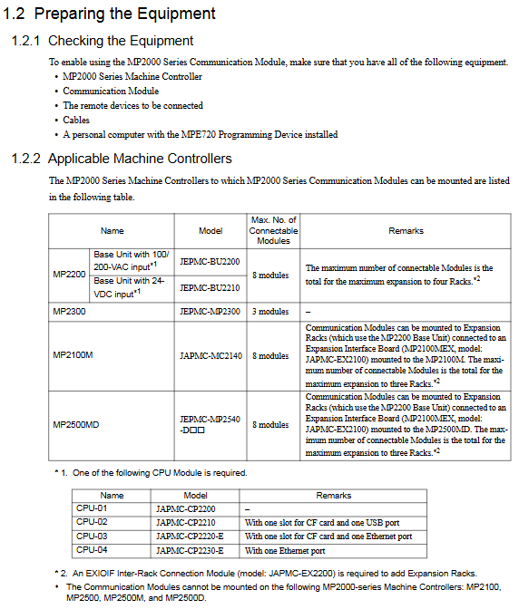
Applicable products: JAPMC-CM23 model communication module, including 6 sub models: 218IF-01, 218IF-02, 217IF-01, 260IF-01, 261IF-01, 215AIF-01
Adaptive controller: MP2000 series machine controller (MP210M, MP2200, MP2300, MP2500MD)
Core functions: Support multi protocol industrial communication, data transmission between devices, engineering debugging and maintenance, and adapt to various interfaces such as RS-232C, Ethernet, DeviceNet, etc
Hardware specifications and installation configuration
1. Core parameters of the module
Module model, communication interface, key specifications, protection level, weight
218IF-01 RS-232C+Ethernet (10Base-T) serial port up to 19.2kbps; Ethernet 10Mbps, TCP/UDP protocol IEC IP00 85g
261IF-01 RS-232C+PROFIBUS compatible with PROFIBUS protocol, industrial bus communication IEC IP00-
215AIF-01 RS-232C+MPLINK/CP-215 supports token passing mechanism and link communication function IEC IP00-
2. Installation and wiring requirements
Environmental conditions: working temperature ≤ 55 ℃, no corrosive gases, vibration ≤ 9.8m/s ², avoid direct sunlight and condensation
Installation specifications: The module needs to be aligned with the guide rail and inserted into the controller slot, with a bolt tightening torque of 2.94N · m. Unused slots need to be equipped with dust covers
Wiring requirements: The distance between the control signal and the power line should be ≥ 30cm, and the grounding wire should be as short as possible (single point grounding); RS-422/485 adopts a 4-wire wiring system and requires 120 Ω terminal resistors to be connected at both ends
Port protection: The FG terminal needs to be reliably grounded, and the cable shielding layer should be connected to the equipment casing to avoid electromagnetic interference
Communication mode and protocol system
1. Three major communication modes
Message communication: Triggered through MSG-SND/MSG-RCV functions, supporting master-slave data exchange and adapting to multiple protocols (MEMOBU, MELSEC, etc.)
Engineering Communication: Used for debugging communication between MPE720 programming software and controller, supporting interfaces such as serial port and Ethernet
Link communication: only applicable to 215AIF-01 module, automatically timed transmission of preset I/O data, based on token passing mechanism
2. Core Communication Protocol
Protocol Name Applicable Interface Core Features Application Scenarios
MEMOBU serial/Ethernet YASKAWA standard protocol, master-slave communication, supports coil/register read/write data transmission between devices of the same brand
Extended MEMOBU Ethernet/MPLINK Extended MEMOBU, supporting up to 508 words of data transmission for large data volume industrial communication
MELSEC serial/Ethernet compatible with Mitsubishi MELSEC PLC, supporting communication between CPUs, buffering communication, and cross brand PLC interconnection
MODBUS/TCP Ethernet Industrial General Protocol, client/server mode, cross vendor device compatible communication
OMRON serial port compatible with Omron SYSMAC PLC, Host Link mode Omron device integration
Non protocol full interface without preset protocol, directly transmitting continuous register data custom protocol scenario
Software Configuration and Programming Implementation
1. Basic configuration process
Communication Manager Settings: Configure logical ports (up to 16), select port types such as serial/Ethernet/CP-215, and set parameters such as baud rate and IP address
Self configured execution: triggered by the DIP switch or MPE720 software of the controller, automatically identifies the module and generates a configuration file
MPE720 parameter settings: Start programming software and configure project communication parameters (logical port, IP address, protocol type)
Transmission definition configuration: Set transmission protocol, master-slave mode, data address, timeout time, etc. for different modules
2. Core programming functions
MSG-SND (Message Sending Function): sends data to remote devices, supports multi protocol selection, core parameters include execution bit, device type, protocol type, circuit number, parameter list address
Input parameters: Execute (start send), Abort (interrupt send), Dev Typ (device type), Pro Typ (protocol type), etc
MSG-RCV (Message Reception Function): Receive remote device data, support automatic/manual reception switching, core parameters correspond to the sending function
Support data offset storage, receive range limitation, and can monitor communication status and error messages
3. Programming Example Scenarios
218IF-01 Ethernet Communication: Master (IP 192.168.1.2) and Slave (IP 192.168.1.3) transmit 100 word data via UDP using Extended MEMOBU protocol
MELSEC PLC connection: Read the D0000-D0063 register data of Mitsubishi PLC, store it in controller MW10000-MW10063, and automatically convert it through MELSEC protocol
Non process protocol communication: Unidirectional transmission of 254 word continuous register data, no response mechanism, suitable for custom protocol interaction
Detailed operation of each module (taking 218IF-01/02 as an example)
Ethernet parameters: IP address (default 192.168.1.1), subnet mask 255.255.255.0, port numbers 256-65535
Serial port parameters: data bits 7/8, parity bits (odd/even/none), stop bits 1/2, baud rate 9600/19200bps
Communication example: Ethernet connection between modules, Master reads Slave’s MW00000-MW00063 data through MSG-SND and stores it locally in MW01000-MW01063
Unique settings: Ethernet (LP) is selected as the logical port, 9999 is set as the engineering port, and the IP address is compatible with 218IF-01
Connection example: Ethernet connection with a personal computer, engineering debugging through MPE720 software, supporting high-speed data transmission
Maintenance and troubleshooting
1. Key points for regular maintenance
Daily inspection: Terminal fastening, cleaning of heat sink (compressed air blowing), no damage to cables
Component replacement cycle: cooling fan 2-3 years, smoothing capacitor 5 years, motor bearing 2 years/12000 hours, fuse 10 years
Safe operation: Before maintenance, the power must be cut off and wait for the capacitor to discharge (CHARGE LED to turn off); Use insulated tools and do not touch CMOS components
2. Common troubleshooting
Common causes and solutions for fault phenomena
Communication timeout (ERROR light on) IP address conflict, port number error, transmission parameter mismatch check network configuration, unified baud rate/checksum and other parameters
Data transmission error: loose wiring, ungrounded shielding layer, electromagnetic interference: re tighten terminals, optimize wiring (away from power lines), and rectify grounding
Hardware malfunction (ERR light flashing) ROM/RAM error, module not recognized, perform self diagnostic test, replace control board, reinstall module
Ethernet connection failure, network cable damage, switch failure, IP configuration error. Replace the network cable, check the switch status, and confirm that the IP is in the same network segment
3. Fault reset method
Trigger reset input signal, press the [RESET] button on the operator, turn off the main circuit power and restart
Reset premise: eliminate the cause of the fault and turn off the external operation command (FWD/REV/ORT)
Core products: VARISPEED-626M5 vector control frequency converter (Model: CIMR-M5) and VS-656MR5 power regeneration converter (Model: CIMR-MR5A), specially designed for high-precision motor drive of industrial equipment such as machine tools, supporting power regeneration function and better energy efficiency.
Voltage and power range:
200V level: frequency converter 5-50HP (3.7-37kW), converter 5-50HP (3.7-37kW, 7-60kVA);
400V level: frequency converter 7.5-60HP (5.5-45kW), converter 7.5-60HP (5.5-45kW, 9-70kVA).
Model naming convention: Taking CIMR-M5A27P5 as an example, “CIMR” is the series prefix, “M5” represents VS-626M5 frequency converter, “A” represents independent system use, “2” represents 200V level, “7P5” represents 7.5HP (5.5kW), and the suffix includes the structural type (0=open chassis type, 5=externally cooled heat sink type) and version number.
2. Core performance parameters
Control method: Sine wave PWM vector control, supporting speed control, torque control, and servo mode switching.
Speed regulation performance: The speed regulation range is from 40r/min to the maximum speed of the motor (up to 8000r/min), with a speed accuracy of ≤ 0.2% (rated speed).
Overload capacity: 120% rated current of frequency converter/1 minute; Converter 120% rated current/1 minute, 200% rated current/1 second.
Environmental adaptability: working temperature 0-55 ℃ (inlet temperature of heat sink ≤ 45 ℃), storage temperature -20-60 ℃, humidity ≤ 95% (no condensation), altitude ≤ 1000m, pollution level 2 environment.
Safety operation standards
1. Classification of safety warnings
Warning: Refers to the risk of fatal or serious personal injury, such as not cutting off power before wiring, operating with open covers, touching high-voltage terminals, etc.
CAUTION: May cause minor injury or equipment damage, such as unauthorized installation, incorrect parameter modification, failure to ground according to specifications, etc.
NOTE: Key operation tips to ensure the normal operation of the device, such as wiring spacing, heat dissipation requirements, etc.
2. Key safety requirements
Power off operation: Before wiring or maintenance, the power must be cut off and the capacitor must be discharged for 5 minutes (after the LED is turned off).
Grounding specifications: 200V level grounding resistance ≤ 100 Ω, 400V level ≤ 10 Ω, independent grounding (not shared with high current equipment such as welding machines and motors).
Installation restrictions: It is strictly prohibited to install on flammable materials. A heat dissipation space must be reserved and an external emergency stop circuit must be equipped.
Prohibited behaviors: Do not modify the product structure, do not connect AC power to the output terminals (U/T1, V/T2, W/T3), and do not conduct voltage withstand tests.
Receiving and unboxing inspection
1. Key inspection points
Model verification: Confirm that the equipment model is consistent with the order, and check the nameplate (including input/output specifications, serial number, weight, etc.).
Appearance and components: Check that the shell is not damaged during transportation, screws and connectors are not loose, and components are not missing.
Exception handling: If there is any damage or discrepancy, immediately contact the YASKAWA agent and do not install or operate it on your own.
2. Interpretation of key information on nameplates
Input specifications: 200V level frequency converter DC 270-325V, 400V level DC 540-650V (powered by the converter).
Output specifications: 3-phase AC 0-230V (200V level)/0-460V (400V level), corresponding to different capacities depending on the model (such as 12.9kVA).
Other identification: PROM version number, serial number (for after-sales traceability), structural type (open/cooled).
Installation specifications
1. Installation environment requirements
Avoid scenarios: direct sunlight, rain, snow, moisture, oil spills, salt spray, corrosive gases, dust/metal particles, severe vibrations, strong electromagnetic interference (such as welding machines), and near flammable materials (diluents, solvents, etc.).
Temperature control: The ambient temperature should be ≤ 55 ℃, and the inlet temperature of the heat sink should be ≤ 45 ℃. A fan or cooling device should be equipped to ensure heat dissipation.
2. Installation spacing and method
Installation method: Vertical installation (ensuring smooth heat dissipation airflow), fixed on the surface of non combustible materials such as metal.
Distance requirement (external cooling type with heat sink):
Front/back: ≥ 120mm;
Left and right sides: ≥ 5mm;
The cooling wind speed near the heat sink is ≥ 2.5m/s.
Open chassis type: front/back ≥ 150mm, left and right ≥ 50mm; when combining a converter of 11kW or more with a frequency converter of 7.5kW or less, the spacing must meet 28mm (horizontal) and 57mm (vertical).
3. Component identification
Core components of frequency converter (VS-626M5): mounting base, 4 mounting holes, heat sink, upper and lower cover plates, main circuit terminals (P/⊕, N/⊖, etc.), control power input terminal CHARGE LED、 7-segment LED display screen, output terminals (U/T1, V/T2, W/T3), grounding terminals, various signal connectors (51CN, 52CN, 6CN, etc.).
Core components of converter (VS-656MR5): main circuit power input terminals (R/L1, S/L2, T/L3), control power input terminals (A1/r, A2/t), DC output terminals (P/⊕, N/⊖), control power output terminals (P1, N1), grounding terminal CHARGE LED、 7-segment LED display screen.
Wiring specifications
1. Safety prerequisites for wiring
Wiring personnel: must be operated by qualified electricians and familiar with electrical safety regulations.
Power off confirmation: Before wiring, make sure the power is completely turned off to avoid electric shock.
Terminal tightening: Tighten the terminal screws (such as M6 screws 26lb in/2.94N · m) to the specified torque to prevent loosening and fire hazards.
2. Main circuit wiring
(1) Core requirements
Voltage matching: Ensure that the power supply voltage is consistent with the rated voltage of the equipment (200V/400V level distinction).
Component installation:
The main circuit needs to be connected in series with MCCB (molded case circuit breaker) to protect the circuit;
The input end of the converter must be equipped with an AC reactor of corresponding capacity (to improve power factor);
Inductive loads (contactors, relays, etc.) need to be connected in parallel with surge absorbers or diodes, and are strictly prohibited from being connected to the output terminal of the frequency converter.
Prohibited connection: The input terminal must not be connected to phase advance capacitors or surge suppressors, and the output terminal must not be connected to AC power supply, phase advance capacitors, LC/RC filters, or magnetic starters.
(2) Wiring Details
Converter and frequency converter connection: The main circuit DC power supply is connected through a dedicated connection bus (P/⊕ → P/⊕, N/⊖ → N/⊖), with a torque of 4-5N · m; the control power supply is connected through a dedicated cable (P1 → P1, N1 → N1).
Motor connection: The output terminals of the frequency converter (U/T1, V/T2, W/T3) correspond to the U, V, and W terminals of the motor, ensuring that the motor rotates counterclockwise under the forward rotation command (load side perspective), with a wiring length of ≤ 20m.
Grounding treatment: Use grounding wires that comply with electrical standards, with the shortest possible length, and use single point grounding to avoid loop grounding (refer to Fig.11 and 12).
3. Control circuit wiring
(1) Signal type and connector
Control signal: including encoder signal (RS-422A specification), 12 bit digital reference signal, analog speed reference signal (0 ± 10V), sequence input signal (forward rotation, reverse rotation, emergency stop, etc.), fault output signal, etc.
Key connectors:
1CN: Control signal (digital reference, encoder output, etc.);
2CN: Encoder signal input, motor thermistor signal, etc;
Separate wiring: Control the distance between the signal line and the main power line to be ≥ 30cm, avoid parallel wiring, and prevent interference.
Cable specifications: Shielded twisted pair cables are used for control signals, and both ends of the encoder signal cable shielding layer are grounded. The cable length is ≤ 20m.
Input method: 12 digit reference and 6CN sequence input support 0V common,+24V common, or external common (requiring 20-26V power supply), wired according to Fig.13 specifications.
4. Wiring inspection
Inspection items: Wiring correctness (refer to the connection diagram), terminal tightness, bare wire without contact with other terminals, no wire debris or screw residue in the equipment, and it is strictly prohibited to use the control circuit buzzer for inspection.
Operation process
1. Operation mode
Online operation mode: Execute user programs and I/O operations, RDY and RUN LEDs light up, ALM and ERR LEDs turn off when there are no faults.
Offline stop mode: Program stops, output reset, RUN/RDY LED off (trigger scenario: no scan time set, memory not initialized, serious fault, etc.).
2. Start the process
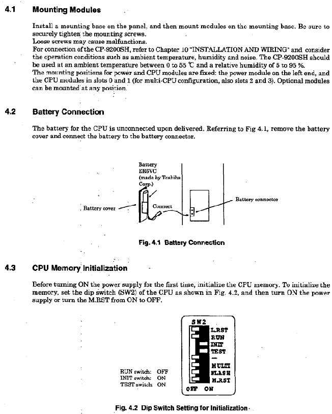
Complete module installation and battery connection (connect CPU battery separately);
Set CPU memory initialization through DIP switch;
Connect CP-717 programming tool;
Load user program;
Start running, the device performs self diagnosis (memory, ROM, CPU function testing).
3. Test Run
Preparation before operation: Clear operational obstacles, notify surrounding personnel, and confirm safety.
Power startup sequence: First turn on the control power supply (or turn it on simultaneously with the main circuit power supply), then turn on the main circuit power supply; The order of closure is reversed.
Status confirmation:
Control power on: converter 7-segment LED displays “- u”, frequency converter displays “- b”;
Main circuit power on: The converter display switches to “- b”, the CHARGE LED red light is on, and the motor cooling fan starts (airflow direction conforms to Fig.16).
Operation: Input the operation signal (FWD/REV), gradually increase the speed reference (starting from 0%), verify the motor rotation (clockwise and counterclockwise), smooth acceleration and deceleration, and no abnormal vibration or noise (kHz level static sound is normal control noise).
4. Interpretation of 7-segment LED display
Inverter display:
– b “: No running instruction (base block);
– r “: Running;
Fault display: alternately display the fault number and fault code (such as “2-42” indicating that the second fault is the disconnection of the motor thermistor).
Converter display:
– u “: The main circuit is not powered on or under voltage;
– b “: Not running;
Fault display: alternately display the fault number and fault code (such as “1-01” indicating that the first fault was overcurrent).
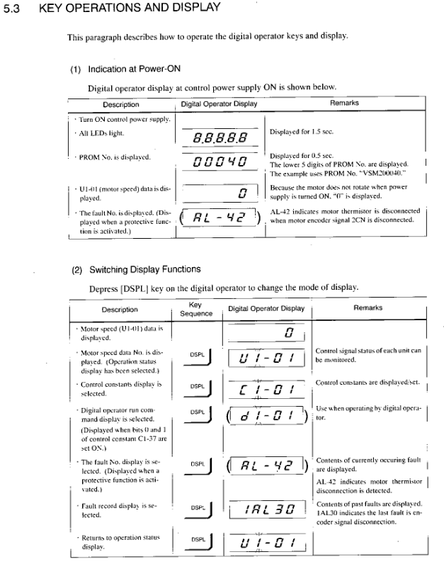
Digital operator (JVOP-132) operation
1. Installation and safety
Installation: Connect through a 3CN connector, use a dedicated extension cable (72616-W5301/5303), tighten the connector screws, and install the cable fixing bracket to prevent detachment.
Safe operation: Before disassembly, the power must be turned off and the capacitor discharge must be completed (LED off).
2. Core functions
Status monitoring: Display operating parameters such as control signal status, motor speed, output current, etc. (refer to APPENDIX 5).
Parameter settings: View and modify control constants (such as speed proportional gain, rated speed, etc., refer to APPENDIX 6), some parameters (C1-25 to 59, etc.) need to be stopped for modification.
Fault handling: Display current fault codes and historical fault records (up to 6), support fault reset.
Independent operation: No external sequence input or speed reference is required, and testing operations such as jogging, forward and reverse rotation can be achieved through the operator (with parameters set to C1-37).
3. Key operations
Mode switching: Press the [DPL] key to switch between operating status display, control constant display, fault display, and other modes.
Parameter modification: Select the constant number → Press the [DATA] key to view the current value → Modify the value → Press the [DATA ENTER] key to write (display “End” for confirmation).
Fault reset: Press the [RESET] key in fault display mode, and before resetting, turn off the external operation command (FWD/REV/ORT).
External terminals, mounting bolts, connectors: no looseness;
Heat sink: no dust accumulation (blown with 4-6kg · cm ⁻ ² dry compressed air);
Printed circuit board: no conductive dust or oil stains (replace if unable to remove);
Cooling fan: No abnormal noise or vibration, needs to be replaced after 20000 hours of operation;
Smooth capacitor: no discoloration or odor (5-year inspection, replace if necessary);
Motor bearings: No abnormal noise or temperature rise, maintained for 12000 hours or 2 years.
2. Component replacement cycle (guide)
Remarks on component replacement cycle
Cooling fan (frequency converter/inverter) to be replaced with new parts within 2-3 years
After a 5-year inspection, decide whether to replace the smoothing capacitor
Determine whether to replace the aluminum electrolytic capacitor on the circuit board after a 5-year inspection
Replace the fuse with a new one after 10 years
Motor bearings require 12000 hours or 2 years of disassembly, maintenance, or replacement
Replace the motor cooling fan with a new one after 15000 hours or 2 years
Contact YASKAWA agent for equipment overhaul of 20000 hours or 5 years
3. Maintain safety regulations
Power off requirement: Cut off the main circuit and control power before maintenance, and confirm that the CHARGE LED and 7-segment LED are turned off (capacitor discharge completed).
Operation restrictions: Only authorized personnel are allowed to operate. Remove metal items such as watches and bracelets, use insulated tools, do not touch CMOS components (which are susceptible to static electricity damage), and do not plug or unplug cables/connectors with power on.
Positioning: Yaskawa CP-9200SH is a high-end industrial controller that integrates sequential control and motion control, designed specifically for industrial machinery that requires high-speed synchronous operation.
Core advantages:
Modular structure, supporting flexible expansion;
Multi axis control capability, capable of controlling up to 224 axes;
Compatible with multiple communication protocols and I/O modules;
Support hot plugging for easy maintenance;
Equipped with comprehensive debugging and fault diagnosis functions.
Hardware system specifications
(1) Core module types and parameters
Module type, key model, core parameters
Power module PS-01 input: 85-132VAC/90-140VDC, power consumption ≤ 150W
PS-02 input: 170-230VAC, power consumption ≤ 150W
PS-03 input: 19.2-28.8VDC, power consumption ≤ 150W
CPU module CP-9200SH CPU 32-bit processor, program memory 1MB/2MB, supports dual CPU configuration
The SVA motion module can control up to 4 axes and supports position/speed/torque control
PO-01 has a maximum of 4-axis pulse output and supports positioning/zero point return
SVB maximum 14 axis MECHATROLINK control, maximum 224 axis expansion
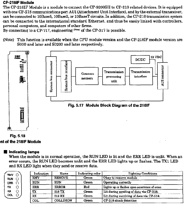
Communication module CP-215IF has a transmission speed of 4Mbps and supports 30 standard sites
CP-217IF supports RS-232/RS-422/485, with a transmission distance of ≤ 300m
I/O module LIO-01 with 32 DI/DO points each
DI-01 DI 64 points
DO-01 DO 64 points
(2) Environmental and Physical Specifications
Working environment: temperature 0-55 ℃ (24-hour average ≤ 50 ℃), relative humidity 5% -95% (no condensation);
Anti vibration: Complies with JIS B 3502, with a half amplitude of 0.075mm at 10-57Hz and an acceleration of 9.8m/s ² at 57-150Hz;
Program structure: Supports parent, child, and grandson layer level structures, with a maximum of 64 drawings.
(2) Core functions
Control functions: position control, speed control, torque control, electronic cam, electronic shaft synchronization;
Communication function: Supports CP-213/215/216/217/218/225/2500 communication protocol, Ethernet (10Mbps);
Debugging and monitoring: data tracking (up to 4 sets x 16 data, 32k word memory), fault tracking (up to 500 fault definitions);
Special functions: pulse counting, frequency measurement, hardware position locking, hot swapping.
Installation and operation specifications
(1) Installation requirements
Installation location: Avoid direct sunlight, high temperature and humidity, dust, corrosive gases, vibration and impact environments;
Module installation: The power module is located on the left, the CPU module is in slot 0/1, and the fastening screws are tightened to prevent loosening;
Wiring specification: Separate the power and I/O lines for wiring, with a spacing of ≥ 200mm, to avoid noise interference.
Hot plugging process: Set the BUS switch to HALT → Confirm that the RMV LED is on → Disassemble the module → Install the new module in HALT mode → Tighten the screws → Switch the BUS switch to ACT → Confirm that the RUN LED is on.
Fault handling and maintenance
(1) Fault diagnosis
LED indicator lights: RDY (ready), RUN (running), ALM (alarm), ERR (error), BAT ALM (battery alarm);
Common faults: power supply error (check voltage range), communication error (check wiring and terminal resistance), program error (check SW00050 error code).
(2) Maintenance points
Battery maintenance: When the BAT ALM light is on, replace the lithium battery (ER6VC) and backup data to prevent loss;
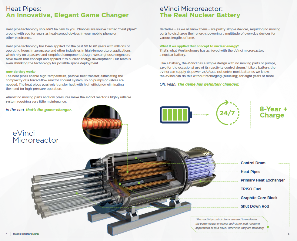
Product positioning: Westinghouse eVinci ™ Micro reactors are “nuclear energy cells” developed based on mature heat pipe technology, aimed at addressing the global demand for innovative, transportable, safe, and reliable zero carbon energy, and filling the energy supply gap in remote areas and special scenarios.
Core technology: With heat pipe technology as the core, this technology has been applied in the fields of aerospace and electronic equipment for 50-60 years, with millions of hours of operating experience; Through passive and efficient heat transfer, there is no need for forced flow cooling systems, completely eliminating moving parts such as pumps and valves, simplifying system complexity.
Core components: TRISO solid fuel, graphite pellets, heat pipes, main heat exchanger, reactivity control drum (power regulation/shutdown), shutdown rods, with no additional moving parts in the overall design.
Key parameters and core characteristics
Category specific specifications
Capacity parameter power generation capacity: 5 MWe; Thermal capacity:~6MWhth
Operating cycle of over 8 years at full power without the need for material replacement
Design features: no moving parts, passive heat transfer, no high-pressure operation, solid fuel technology
Construction and deployment of full factory assembly, ground construction, railway/barge transportation, rapid deployment, and scalability
Built in strong security features, no high risks associated with traditional nuclear power, supporting deployment in city centers/campuses
Environmentally friendly zero carbon emissions, replacing diesel generators and reducing carbon footprint
Only a small number of personnel are needed for operation and maintenance on site, with extremely low maintenance requirements
Analysis of Core Advantages
Innovation and Efficiency: Heat pipe technology simplifies traditional reactor systems, eliminates complex components such as pumps and valves, and achieves high passive heat transfer efficiency without the need for high-pressure operation, reducing the risk of failure.
Transportable deployment: After the entire factory assembly is completed, it can be transported by railway or barge without complex on-site construction, and can be quickly deployed in areas without power grid coverage.
Ultimate safety: Using solid-state TRISO fuel and graphite pellets, there is no high pressure or large demand for cooling water resources. The passive safety system minimizes the risk of accidents and is suitable for sensitive scenarios such as cities and campuses.
Reliable and Durable: Designed with no moving parts to enhance stability, it can operate continuously in harsh environments, with 24/7 uninterrupted power supply and no need for material replacement for over 8 years, reducing maintenance costs.
Environmental Collaboration: Zero carbon power generation can provide regional heating and seamlessly collaborate with renewable energy sources such as wind, solar, and hydropower to help decarbonize the energy structure.
Core application scenarios
Scenario type, specific scenario application value
Replace diesel generators in remote/special off grid communities, mines, military bases, and oil and gas operation areas to solve fuel transportation problems and provide stable zero carbon electricity
Research universities in institutional settings provide electricity and regional heating to support decarbonization; Provide a platform for nuclear technology research and talent cultivation
Renewable energy supporting renewable energy in energy synergy scenarios compensates for the intermittent shortcomings of wind and solar energy, and builds a stable zero carbon energy system
Deployment and Regulatory Progress
Deployment advantages: Ground construction does not require complex underground engineering, rapid deployment and support for large-scale expansion, on-site operation, maintenance, and security only require a small number of personnel.
Regulatory status: Actively promoting regulatory approvals in the United States and Canada, laying the foundation for subsequent commercial deployment.
Value added: In addition to electricity supply, it can provide process heat for regional heating, helping remote communities and institutions achieve sustainable economic development.
G Framework (16-125A): Suitable for small current circuit protection, cable cross-section 3-95mm ², size (H × W × D) 130 × 25 × 76.8mm (1P), weight 0.3kg-0.9kg, supports DIN rail installation, connects miniature circuit breakers with industrial grade plastic case circuit breakers.
K frame (250-630A): Short circuit breaking capacity up to 100kA, cable cross-section 95-500mm ², size 257 × 140 × 108mm (3P), weight 4.1kg-5.8kg, supports busbar connection, suitable for industrial heavy-duty circuit protection.
N-frame (1000-1250A): Electronic Release (LSIG), size 406 × 210 × 140mm (3P), weight 21.3kg-28.3kg, pull-out installation, used for incoming line protection of large distribution systems.
Installation and connection method
(1) Installation type
Fixed: All frames are supported and directly fixed to the distribution board, making installation convenient.
Plug in: F/J/K/L/N frame adaptation, front side disassembly is achieved through plug-in adapters for easy maintenance.
Pull out type: J/K/L/N frame adaptation, including movable mechanism and fixed cassette, supporting circuit breaker pull out maintenance without affecting the main circuit.
(2) Connection specifications
Frame number connection method, cable cross-section
G-frame cable connection 3-95mm ²
F-frame cable connection 2.5-150mm ²
J-frame cable/busbar connection 50-185mm ²
K frame cable/busbar connection 120-500mm ²
L/N frame busbar connection 95-500mm ²
Core accessory system
Accessory Type Function Description Adaptation Framework
Auxiliary switch 1NO+1NC conversion contact, used for signal feedback of the entire frame
Shunt Trip remote control circuit breaker opening, supporting AC/DC voltage full frame
Undervoltage Release automatically opens when the voltage is insufficient, protecting the entire equipment frame
Padlockable Handle locks the ON/OFF position to prevent accidental operation of the entire frame
Pull out cassette specifically designed for pull-out installation, including secondary terminal block J/K/L/N frame
Electric opening and closing of motor operating mechanism, supporting local/remote operation of the entire framework
Plug in adapter for plug-in installation, simplifying disassembly of F/J/K/L/N frames
Rotate the handle mechanism to change the direction of operation and adapt to the installation of the entire cabinet door frame
Key performance characteristics
release characteristics
Overload tripping: The thermal magnetic type generates heat through bimetallic plates, while the electronic type detects current through electronic components; Adjustable thermal release range 0.7-1.0In.
Short circuit release: Magnetic release fixed 5In or adjustable 5-10In, instantaneous breaking time ≤ 0.1s.
Ground fault protection: The electronic LSIG release supports ground fault detection and tripping.
environmental adaptability
Temperature adaptation: The 40 ℃ series operates at full load at an ambient temperature of 40 ℃, while the 55 ℃ series is suitable for high temperature scenarios.
Mechanical/electrical lifespan: Mechanical lifespan is 7000-14000 cycles, electrical lifespan is 2000 cycles (In, 415V AC).
safety protection
Insulation protection: The creepage distance and electrical clearance comply with IEC standards, and the terminal protection cover reaches IP30 level.
Reliability of breaking: After short circuit breaking, it can be repeatedly closed, Ics=70%-100% Icu, Ensure that it can still be used normally after disconnection.
Product series MAX-VH ™ (Standard efficiency) MAX-VHP ™ (NEMA efficient)
Motor type: squirrel cage induction motor (SCIM)
Power range: Low voltage: 7.5-800 HP; Medium voltage: 200-1000 HP
Voltage adaptation for low voltage: 230V/460V (208V compatible), only 460V for 150 HP and above; medium voltage: 2300V/4000V
Frequency adaptation 60 Hz (low voltage compatible 50 Hz)
Synchronous speeds of 900 RPM, 1200 RPM, 1800 RPM
Service coefficient 1.15 (sine wave power supply); 1.0 (PWM power supply)
Weather Protected Type 1: IP23; TEFC type (Completely Enclosed Fan Cooled): IP55
Certification standards NEMA MG-1, MG-13; Test standard: IEEE-112 (Method B/F)
Warranty period of 36 months (from production date)
Structural Design and Core Configuration
(1) Key materials and construction
Rack and connectors: High grade cast iron rack, flange bracket (P-Base), upper bracket, TEFC type with oil tank design (324TP-5810P).
Shaft system: 1045 carbon steel hollow shaft, ensuring high strength and transmission reliability.
Core and winding: C5 grade cold-rolled electromagnetic steel core; The stator winding adopts polyester enameled copper wire (low voltage), mica+glass insulated formed coil (medium voltage 449TP and above), F-class insulation system, and is treated with immersion paint baking.
Power supply fluctuation: voltage ± 10%, frequency ± 5%, combined fluctuation ± 10% (frequency fluctuation ≤± 5%).
Installation method: Flange installation (IM3011), only supports direct coupling transmission.
Main series and key parameter table
(1) Low voltage series core parameters (460V, 1800 RPM)
Series model example Power (HP) Frame number Full load efficiency (%) Full load current (A) Downward thrust (LBS) Approximate transport weight (LBS)
MAX-VH ™ VH0754FP 75 365TP 94.1 88.5 6000 989
MAX-VH ™ VH4004FP 400 449TP 95.4 444 13200 3818
MAX-VHP ™ VHP1504 150 444TP 95.8 171 10700 1815
MAX-VHP ™ VHP8004 800 5810P 96.2 859 30100 6400
(2) Core parameters of medium voltage series (4000V, 1800 RPM)
Series model example Power (HP) Frame number Full load efficiency (%) Downward thrust (LBS) Approximate transport weight (LBS)
VHKP VHKP5004 500 5009P 95.0 30900 3980
VHKP VHKP10004 1000 5810P 95.0 30100 6510
Additional configurations and optional features
Standard configuration: wedge key, non reversing pawl (NRR, ball type spark free design), heavy-duty beryllium copper ball, junction box internal/external grounding terminal.
Optional configurations: Stable liner, alternative upper coupler, alternative P-Base size, digital/analog metering kit.
Coupling kit: Each motor includes 1 set of couplers, and individual purchases need to be priced according to the list. The BX size tolerance is strictly controlled (≤ 1.5 inches:+0.001/-0.000 inches; > 1.5 inches:+0.0015/-0.000 inches).
Certification and standards comply with IEC 61439-1/2, ASTA/KEMA certification, and have passed tests such as temperature rise, dielectric performance, and short-circuit withstand
Detailed explanation of core product series
(1) Three phase distribution board series
Series rated current output line number, installation method, core characteristics
Ci series 250A 2-16 surface/embedded short-circuit withstand 25kA/3s, 35kA/1s, IP43 protection
Gi series 400A 2-18 surface/embedded fully supported busbars, with a maximum output circuit breaker of 225A
Fi series 630A 4-18 channel surface/embedded no capacity reduction design, IP43 protection
Ki series 800-1250A 6-18 surface mounted short-circuit withstand 50kA/1s, 35kA/3s, 2.0mm steel plate shell
Bi series 125-250A 4-16 channel surface/embedded/double-layer modular combination, supporting MCB/MCCB/RCCB incoming lines
PQ series 125-250A 4-16 surface/embedded/plug-in plug-in outlet, easy to install
(2) Single phase distribution board series
Series rated current output line number, installation method, core characteristics
COJ series (plug-in) 100-125A 4-14 surface/embedded maximum cable capacity 25mm ², IP43 protection
Din Rail series (rail type) 100A 4-14 road surface/embedded support DIN rail installation, suitable for residential scenes
Key Performance and Security Protection
Electrical performance
Short circuit withstand current: 25 kA/3s(Ci/Gi/Fi)、35kA/1s(Ci/Gi/Fi/Ki)、50kA/1s(Ki/800A+MDB)、100kA/1s(6400A MDB)
Bus temperature rise: ≤ 80K (vertical/horizontal installation)
Voltage adaptation: 380/415V, 600V AC Max
safety protection
Physical protection: IP43 (solid object and splash proof), IP54 (MDB, dust and spray proof)
Structural protection: fully isolated live parts, door lock design to prevent misoperation, blank board covering idle outlet ports
Grounding system: internal and external grounding terminals, neutral wire and grounding busbar separation design
Installation and accessory system
Installation method
Surface installation: suitable for scenarios with sufficient space, easy to install
Embedded installation: saves space, adapts to wall embedding
Plug in installation: exclusive to PQ series, easy to quickly replace modules
Key electrical parameters insulation resistance: random winding ≥ 5M Ω, formed winding ≥ 100M Ω (calibrated at 40 ℃); Voltage fluctuation is allowed within ± 10%; Frequency fluctuation allowed ± 5%
Appearance inspection: No collision or damage, take photos to record transportation damage and synchronize with the carrier and manufacturer.
Parameter verification: The rated power, voltage, and frequency on the nameplate are consistent with the order, and the attachments (instruction manual, accessories) are complete.
Key verification: The directional arrow markings are clear, and the parameters of auxiliary equipment such as heaters and temperature detectors are compliant.
(2) Storage Management
Storage environment: Clean, dry, well ventilated, temperature between 10-50 ℃, away from boilers/cold storage, avoid vibration (≤ 2.5mm/s), and place the motor on a tray to prevent moisture.
Moisture prevention measures: Use space heaters (according to nameplate voltage) or built-in incandescent lamps to maintain motor temperature 3 ℃ above dew point; Rotate the motor shaft several times a month to avoid bearing corrosion.
Regular testing: Conduct insulation resistance testing and temperature detector resistance calibration every 3 months.
Long term storage (≥ 6 months): Supplement lubrication for bearings, drain water cooling pipelines, remove couplings, and lift electric brushes for protection.
(3) Installation specifications
Basic requirements: A rigid base plate/common base should be used, and the foundation should bear the weight and thrust load of the motor, with a horizontal error of ≤ 0.04mm.
Transmission installation:
Couplings: Alignment error (rigid couplings ≤ 0.04mm/flexible couplings ≤ 0.05mm at speeds<2500rpm), end clearance ≤ 2.4mm.
Belt drive: Belt speed ≤ 35m/s, pulley diameter ratio (flat belt ≤ 5:1/V belt ≤ 8:1), pulley installed near the motor body.
Electrical wiring: compliant grounding, cable cross-section matching current, correct starting method and protector parameters, phase sequence verification to ensure correct direction of rotation.
(4) Run operation
Pre startup inspection:
Electrical: The wiring is correct, the insulation resistance meets the standard, and the protector is ready.
Mechanical: Bearing oil level (center of oil gauge), smooth rotation of oil ring, and no foreign object interference.
Auxiliary: The inlet water temperature of the water-cooled motor is 5-30 ℃, and the forced ventilation fan is started 15 minutes in advance.
Start limit: Up to 2 starts in cold state, only 1 start in hot state; Startup failure requires cooling for 30-60 minutes before attempting again. If the rotor does not rotate for 1-2 seconds, immediately stop the machine for troubleshooting.
Operation monitoring: As the load gradually increases, real-time monitoring of three-phase current (imbalance ≤± 5%), bearing temperature (≤ 95 ℃), and vibration (≤ 3.8mm/s) is carried out.
Maintenance and upkeep core
(1) Maintenance cycle and project
Key requirements for maintenance cycle core projects
Daily oil level check, oil ring rotation, leakage monitoring. The oil level is at the center of the oil gauge and there is no dripping or leakage
Every month, the bolts are tightened, the coupling is in good condition, and the filter is clean. All bolts are not loose, and the filter is not clogged
Quarterly insulation resistance testing and bearing grease replacement. If the insulation resistance is ≥ 5M Ω, grease should be added according to the bearing model (such as 6310, add 40g)
Every six months, the winding/exterior is cleaned and the oil is replaced. The winding is free of dust and oil stains, and the sliding bearings are replaced with rust proof turbine oil
Open the cover for inspection every 2 years (without disassembling the rotor) to ensure that the coil does not change color and the bearings are not corroded
Disassemble and inspect the rotor bars and stator windings every 4 years for comprehensive testing
(2) Core component maintenance
Winding maintenance:
Cleaning: Compressed air (≤ 4kg/cm ²) or vacuum cleaning, wipe oil stains with safe solvents (chlorine containing solvents are prohibited).
Moisture proof: Use the space heater when idle to avoid coil condensation.
Testing: Measure with a 500VDC/1000VDC megohmmeter. If the resistance does not meet the standard, it needs to be dried.
Bearing maintenance:
Lubricating medium: default ExxonMobil Polyrex EM grease, mixing different types of grease is prohibited.
Lubricating specification: According to the bearing model (such as 6310, lubricate 40g every 2000 hours), lubricate during operation and then empty load for 10-30 minutes to remove the old grease.
Sliding bearings: Keep the oil level at the center of the oil gauge, change the oil every 6 months, and select the viscosity of the oil according to the number of poles (ISO VG32 for 2-pole).
Maintenance of transmission system:
Couplings: Regularly check the tightness of bolts, and realign if there is any abnormal vibration during operation.
Belt drive: Maintain uniform tension, with pulley diameter ≥ minimum recommended value (e.g. 45kW 4P motor V pulley ≥ 265mm).
Troubleshooting and Handling
Common causes and solutions for fault phenomena
Unable to start (no movement), power outage, broken wiring, missing fuses. Check power supply, repair wiring, install matching fuses
Overheating and overload during operation, ventilation blockage, excessive ambient temperature to reduce load, cleaning ventilation ducts, and improving environmental heat dissipation
Bearing high temperature/abnormal noise, insufficient lubrication, improper installation, bearing wear, replenishment of lubricating grease/oil change, re alignment, replacement of bearings
Excessive vibration, unbalanced rotor, insufficient foundation stiffness, eccentric rotor dynamic balance correction of coupling, reinforcement of foundation, adjustment of coupling
Recycling and Compliance
Material classification: Steel frame, copper winding, cast iron components are classified and recycled, and insulation materials are disposed of according to local regulations.
Hazardous waste: Lubricating oil is classified as hazardous waste and requires compliant recycling. Random discharge is prohibited.
Permanent magnet motor: Before recycling, it needs to be heated to 300 ℃ for demagnetization to avoid magnetic field interference with electronic devices.
Operation mode: ECO energy-saving mode can adjust the engine speed according to the load, reducing fuel consumption and noise; Non ECO mode is suitable for high-power devices such as air conditioning and water pumps.
Output interface: including 120V 20A NEMA 5-20R dual socket, 120V 30A NEMA TT-30R socket, dual USB 5V/2.1A interface, to meet the simultaneous power supply of multiple devices.
Digital data center: Real time display of remaining operating time, output power (kW), fuel level (liters), voltage, and cumulative operating hours.
Parallel operation: Connect generators of the same model through dedicated parallel cables (to be purchased separately) to increase total power output. Parallel operation is not supported in ECO mode.
(2) Operation process
Preparation before startup: Add 87-93 unleaded gasoline (ethanol content ≤ 10%, E15/E85 prohibited), check the oil level, ensure the load is disconnected, and confirm that the equipment is placed outdoors in a dry and flat area (at least 5 feet away from doors and windows).
Startup steps: Turn on the fuel switch → Turn on the battery switch → Select the startup mode (remote control press for 1 second/electric start press for 2 seconds/manual start) → Wait for the “output ready” LED to light up → Connect the load (in the order of “high power priority”).
Shutdown steps: Disconnect all loads → Run without load for a few minutes → Press the shutdown button/remote control to stop → Turn off the battery switch and fuel switch.
Safety standards and protection mechanisms
(1) Safety usage requirements
It must be used outdoors in a well ventilated area. It is strictly prohibited to operate in enclosed spaces such as indoors, garages, and basements to avoid carbon monoxide poisoning. It is recommended to equip a carbon monoxide detector.
Avoid use in damp environments, prevent rainwater and spray from contacting equipment, as damp environments can easily cause short circuits and electric shocks.
Maintain a ventilation gap of 5 feet around the equipment, keep away from combustibles, and have the exhaust outlet facing the unmanned area.
Before refueling, it is necessary to stop the machine and cool it down for 5 minutes. Smoking or approaching open flames are prohibited to avoid fuel spillage.
(2) Multiple protection functions
Protection type triggers condition protection action
Overload protection cuts off AC output when the output current exceeds the rated value, and the overload LED lights up
Low oil level protection: If the oil level is below the safety threshold, the machine will automatically shut down and the low oil LED will light up
Overcurrent protection: When the current exceeds 200% of the rated value, the output is immediately cut off
Overvoltage/undervoltage protection 230V input:>410VDC/<190VDC; 460V input:>810VDC/<380VDC Cut off output to avoid equipment damage
Grounding fault protection detection triggers protection shutdown due to abnormal grounding
Overheating protection: The engine or inverter will automatically shut down and cool down if the temperature is too high
Maintenance and Storage
(1) Regular maintenance cycle and project
Core projects of maintenance cycle
Check the oil level, fuel level, cable and socket status before each use
First 25 hour/1 month engine oil change
Change engine oil and clean air filter every 50 hours/6 months
Clean spark plugs and spark arresters, check fuel filters, and adjust valve clearances every 100 hours/6 months
Replace spark plugs, air filters, and fuel filters every 300 hours/year
(2) Storage requirements
Storage duration operation requirements
No special treatment required for less than 1 month, keep the fuel tank sealed
Add fresh gasoline and fuel stabilizer every 2-6 months, and empty the carburetor float chamber
Drain the fuel tank and carburetor, inject a small amount of oil into the cylinder, and disconnect the battery connection for at least 6 months
Common troubleshooting
Common causes and solutions for fault phenomena
Unable to start battery shutdown, low fuel, wet/faulty spark plug, clogged air filter to open battery, refuel, dry/replace spark plug, clean air filter
Shutdown after startup due to low fuel level, fuel contamination, clogged air filter, oil replenishment, replacement of fresh fuel, and cleaning of air filter
No output power overload triggering protection, circuit breaker tripping, load fault disconnecting load, resetting circuit breaker, checking load equipment
Insufficient power, poor fuel quality, clogged air filter, unadjusted fuel replacement at high altitude, clean air filter, installation of high-altitude carburetor kit (>2000 feet)