Yokogawa AQ6377E Optical Spectrum Analyzer Remote Control
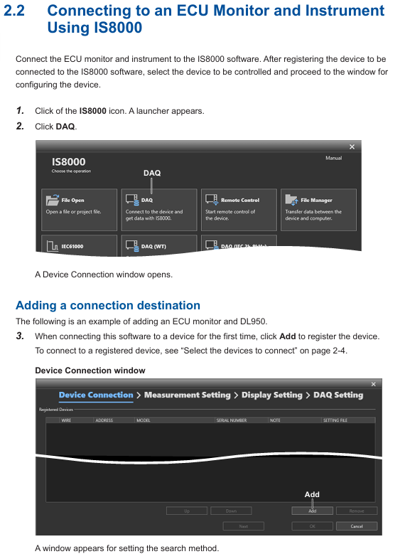
Function positioning
Focus on the remote control function of AQ6377E, provide detailed instructions on the configuration methods of GP-IB interface and Ethernet interface, as well as the use of communication instructions, and support the setting of measurement parameters, data acquisition, and automated analysis of equipment through external controllers (such as PCs).
Remote control core functions and interface configuration
(1) Remote control basic functions
Control mode switching:
Local → Remote: The controller sends a listening address containing REN (Remote Enable) and ATN set to “True”. The device enters remote mode, the REMOTE indicator light is on, and only the LOCAL key is available; If receiving LLO (local lock) messages, the LOCAL key is also disabled, and the controller needs to set REN to “False” to unlock.
Remote → Local: Press the device LOCAL button (non local lock state), or the controller sends a GTL (return to local) message, the device returns to local mode, the REMOTE indicator light goes out, and all buttons are restored to available.
Command sending and receiving mechanism:
Buffer: Input buffer (4 MB, discard excess data), output buffer (4 MB, overwrite old data with new data), error buffer (only stores the latest error information).
Message terminator: Program messages support EOI signals, LF characters LF+EOI; The response message is fixed as LF+EOI; Binary waveform transmission only supports EOI.
Timeout setting: It is recommended to set the controller timeout to 30 seconds or more, as the device automatically adjusts the offset every 10 minutes (taking about 30 seconds) to avoid communication interruption; If you need to shorten the timeout, you can manually turn off the automatic offset (instruction: CALibration: ZERO off) and manually execute the offset during the measurement gap (instruction: CALibration: ZERO once).
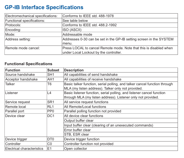
(2) GP-IB interface configuration and specifications
Hardware connection:
Use a 24 pin GP-IB cable that complies with the IEEE 488-1978 standard. Before connecting, turn off the power to the device and controller to avoid circuit damage;
The screws of the cable connector need to be tightened. A single bus can connect up to 15 devices (including controllers), with a total length of no more than 20 meters. It supports Daisy chain or star topology and circular connections are prohibited.
Function and specifications:
Function: Supports listening (receiving controller commands) and dialogue (outputting data to the controller), but does not support listening only, dialogue only, or controller functions;
Electrical specifications: comply with IEEE 488-1978 (electromechanical) and IEEE 488.2-1992 (protocol), address range 0-30, encoded as ASCII;
Interface message response: Supports IFC (interface clearing), REN (remote enable), GTL (return to local), SDC (selected device clearing), etc., does not support IDY (recognition), PPC (parallel polling configuration).
Address and instruction format settings:
Enter SYSTEM → More 2/4 → Remote Interface → GP-IB, and in GP-IB Setting → My Address, use the knob or directional keys to set the address (0-30), ensuring that the device address in the bus is unique;
The instruction format supports AQ6377E native mode (default) or AQ6317 compatible mode, which can be set through Command Format. The compatibility mode should refer to the AQ6317 instruction mapping table in the appendix.
(3) Ethernet interface configuration and specifications
Hardware connection:
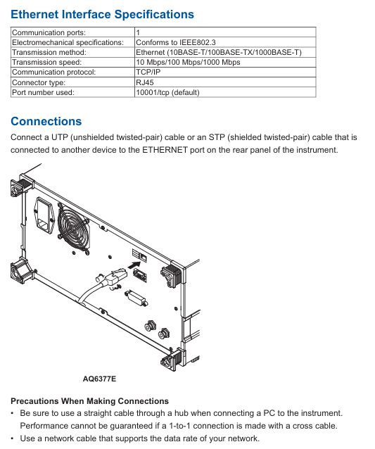
Use UTP (unshielded twisted pair) or STP (shielded twisted pair) cables to connect to the local area network through the RJ45 interface of the device’s rear panel;
Connecting to a PC requires the use of a hub with a direct cable, and the performance of cross cable direct connection cannot be guaranteed; The cable needs to match the network speed (10/100/1000 Mbps).
Function and specifications:
|Parameters | Specifications|
|Communication port | 1|
|Standard compatibility | IEEE 802.3|
|Transmission method | Ethernet (10BASE-T/100BASE-TX/1000BASE-T)|
|Transmission rate | 10/100/1000 Mbps (adaptive)|
|Communication Protocol | TCP/IP|
|Default port number | 10001/tcp (Socket communication)|
|Remote monitoring port | 20001/tcp (fixed, requires dedicated software)|
Network configuration steps:
Go to SYSTEM → More 2/4 → Remote Interface, select WORK (SOCKET) or WORK (VXI-11) as the communication interface;
Go to Network Setting → TCP/IP Setting, configure IPv4/IPv6:
IPv4: Select AUTO (DHCP) to automatically obtain the address, or manually set the IP address, subnet mask, and default gateway using MANUAL;
IPv6: Select AUTO for automatic configuration, or manually set IP address, subnet prefix length, and default gateway using MANUAL;
(Socket communication specific) Set remote port number (default 10001), user account (default anonymous, password optional), timeout period (0-21600 seconds, 0 is infinite timeout);
(Optional) Enable remote monitoring (Remote Monitor → Monitor Port=On), supports PC remote viewing of device screens, requires dedicated software.
Authentication and Instruction Format:
Socket communication requires authentication through the OPEN command, for example: OPEN “username”, supports plaintext or MD5 encryption authentication. After successful authentication, the device returns “READY” and lights up the REMOTE light;
The instruction format is consistent with GP-IB and supports AQ6377E native mode or AQ6317 compatible mode. To disconnect, the CLOSE instruction must be sent.
Programming specifications and instruction explanations
(1) Basic rules of programming
Instruction syntax:
Long Short Format: Supports both short format (uppercase part) and long format, such as: Initiatiate, which can be abbreviated as: Initiate;
Case insensitive: The device does not distinguish between uppercase and lowercase when receiving instructions, and the return value is uniformly capitalized;
Parameter Separation: Instructions and parameters should be separated by spaces, and multiple parameters should be separated by commas (spaces can be added before and after commas to improve readability);
Numerical representation: Supports multiple unit suffixes (such as nm, μ m, GHz), automatically converted to basic units during transmission (such as+1.550000E-006 m for 1550 nm transmission), and automatically rounded off when accuracy exceeds the device’s processing range.
Instruction type:
Sequential instruction: The next instruction can only be executed after completion, such as CALCulate: DATA? (Query and analysis results);
Overlapable instructions: During execution, other instructions can be executed in parallel, such as Initiatate;
Overlapping instructions: can only run during the execution of overlapping instructions, such as ABORt (stop measurement), * STB? (Read status byte).
Multi instruction transmission: Multiple instructions can be separated by semicolons in a single output statement and executed in order, such as SENSe: WAVelengath: STARt 1500NM; :STOP 1600NM。
(2) Detailed explanation of core instruction grouping
The manual divides instructions into 16 core groups, covering scenarios such as measurement control, data processing, system configuration, etc. The key groups are as follows:
ABORt Group:
Core instruction: ABORt: Stop measurement, calibration and other operations (such as scanning initiated by Initiatate and calibration initiated by CALibration), which belongs to overlapping instructions.
CALCulate Group:
Function: Implement spectral analysis (such as THREE/ENVELOPE/RMS spectral width analysis), peak/valley search, marker control, trace calculation (such as mathematical operations of Trace C/F/G);
Example of Key Instructions:
CALCulate: CATegg SWTHresh: Choose the THRESH method for spectrum width analysis;
CALCulate: MARKer: MAXimum: Search for peaks on the activity trace and place moving markers;
:CALCulate:DATA? Query the latest analysis results (requires first executing CALCulate [: IMMediate] to start the analysis).
SENSe Group:
Function: Configure measurement parameters such as wavelength range, resolution bandwidth, sensitivity, scanning speed;
Example of Key Instructions:
SENSe: WAVelocity: CENTer 1550NM: Set the measurement center wavelength to 1550 nm;
SENSe: BANDWidth: RESolution 0.1NM: Set the resolution bandwidth to 0.1 nm;
SENSe MID: Set the measurement sensitivity to MID mode.
MMEMory Group:
Function: Manage file operations, such as saving/loading trace data, setting files, and graphic files;
Example of Key Instructions:
MMEMory: STORe: TRACe TRA, CSV, “test. csv”, INTernal: Save Trace A data in CSV format to an internally stored test. csv file;
MMEMory: LOAD: SETTing “setting. stc”, EXTernal: Load the setting file “setting. stc” from external storage (such as USB).
Common Commands Group:
Compliant with IEEE 488.2 standard, the key instructions are as follows:
|Instructions | Functions | Examples|
|*CLS | Clear all event status registers | * CLS|
|*IDN? |Query device identification (manufacturer, model, serial number, firmware version) | * IDN? → YOKOGAWA,AQ6377E,123456789,1.00|
|*OPC | OPC bit of standard event status register after operation completion | * OPC|
|*RST | Device reset, restore default state (except GP-IB address and calibration data) | * RST|
|*TRG | Perform a single scan (ignore current scan mode) | * TRG|
|*WAI | Wait for the current instruction to complete before executing the next one |: Initialize; *WAI; :CALCulate:DATA? |
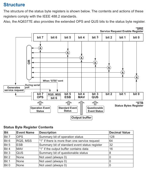
(3) Status Register
The device complies with IEEE 488.2 and SCPI standards, and includes four types of status registers for monitoring the device’s operating status:
Status Byte Register (STB):
An 8-bit register that contains a summary of the overall device status, such as OPS (Operational Status Summary, bit7), ESB (Standard Event Summary, bit5), MAV (Output Buffer with Data), bit4);
Reading method: * STB? (Query current value, do not clear) or serial polling (clear RQS bit after reading).
Standard Event Status Register (ESR):
8-bit register, records device events such as PON (power on, bit7), CME (instruction error, bit5), OPC (operation completed, bit0);
Reading method: * ESR? (Clear the register after querying);
Enable control: By setting the enable register through * ESE, only the event corresponding to the enable bit will trigger the ESB digest.
Operation status register:
Contains operation condition registers (real-time status, such as scanning and calibration), operation event registers (latch events, such as scan completion), and operation enable registers (controlling which events trigger OPS digest);
Reading method: STATus: OPERation: CONDition? (Conditional register),: STATus: OPERation: EVENT? (Event register, cleared after querying).
Suspicious Status Register:
The function has not been allocated yet, all bits are fixed to 0, and the reading method is similar to the operation status register.
Program functionality and automated measurement
(1) Program Editing and Execution
Program registration and editing:
Go to APP → Program → Execute, select the program number (such as 01-99), and set the program name (up to 56 characters);
Supports inserting/deleting/copying rows, editing parameters, and can select functional commands (such as scanning, analyzing) or special commands (such as looping, conditional judgment) through Command Select.
Program execution:
Select the target program, click Execute to start, and during execution, the output data can be viewed through the Output Window;
Supports pause (PAUSE instruction), data input (DATA INPUT instruction, receiving user input values), and data output (DATA OUTPUT instruction, outputting variables or strings to the window).
Program saving and loading:
Save: The program can be saved as PGC format file (approximately 13 KB), stored in internal memory or USB, supports automatic naming (by serial number or date);
Loading: Loading programs from storage media, supporting overwriting or merging existing programs.
(2) Program Control Instructions and Variables
Variable type:
General variables: such as E, G-K, O-V, X-Z (numerical), A-D (string)
Tag variables: such as WM (moving marker wavelength), L1 (fixed marker 1 level), W2-W1 (marker 1-2 wavelength difference);
Analyze variables such as SPWD (spectral width), MEANWL (center wavelength), WDMCHN (number of channels detected by WDM analysis).
Program control instructions:
Loop control: such as N=10; N=N-1; IF N<>0 GOTO 10 (10 cycles);
Conditional judgment: If IF F1<=SPWD<=F2 GOTO 20 (if the spectral width is within the range of F1-F2, skip to line 20);
External control: such as SEND LAN A $, 10001, “* IDN?” (sending instructions to external devices specified by variable A through LAN)
, 10001, “*IDN?”; B (Receive external device responses and store them).
(3) Example Program
The manual provides two typical examples, covering remote measurement and data storage scenarios:
Example 1: Parameter Setting and Spectral Analysis:
Function: Set measurement parameters (center wavelength 1550 nm, span 10 nm, sensitivity MID), perform a single scan, perform frequency spectrum width analysis using the THREE method, and output the results to the PC;
Key steps: Connect the device through the PyVISA library (supporting GP-IB/Socket/VXI-11), send the SENSe command to configure parameters, initiate scanning, perform analysis using CALCulate, and wait for WAI to complete before reading the results.
Example 2: Screenshot saving:
Function: Save the device screen as a PNG format file and load it to the PC via file transfer command (path C: \ test. png);
Key steps: Send: MMEMory: STORe: GRAPhics Save screenshot to internal storage,: MMEMory: DATA? Read binary data from the file and write it to a local file on the PC.
Appendix and Compatibility
(1) Key Appendix Content
Correspondence table between soft keys and remote commands:
List the remote commands corresponding to all panel soft keys of the device, such as the Peak Search soft key corresponding to CALCulate: MARK: MAX imum.
AQ6317 compatible instruction table:
Provide instruction mapping between AQ6377E and the old model AQ6317, such as the CWL of AQ6317 corresponding to the SENSe: WAVelocity: CENTer of AQ6377E.
Output format of analysis results:
Provide a detailed explanation of the output structure of various analyses (such as WDM, EDFA-NF), including data order, units, and accuracy.
(2) Compatibility and Precautions
Model compatibility:
Support compatibility with commands and programs of old models such as AQ6317 and AQ6370D, with some commands requiring parameter format adjustment (refer to Appendix 6-7).
Operation taboos:
Prohibit disconnecting communication connections during program execution to avoid data loss;
During remote control, it is prohibited to use both GP-IB and Ethernet interfaces simultaneously;
When saving/loading files, ensure that the storage medium (such as USB) is properly mounted to avoid file damage.