Call us 24/7uaedcs@163.com
Welcome to the official website of CNIACS Automation Technology Co., Ltd!
Call us 24/7uaedcs@163.com

Allen Bradley 1746-NI8 Analog Input Module

Product Core Positioning and Characteristics

(1) Basic positioning

1746-NI8 is an 8-channel analog input module of the SLC 500 series, used to collect DC voltage or current signals from industrial sites (such as sensor and transmitter outputs), convert analog signals into digital signals recognizable by PLC through built-in analog-to-digital (A/D) converters, achieve equipment status monitoring and process control, and adapt to fixed and modular SLC 500 processors.

(2) Core functions and hardware features

Category specific description

Hardware design -8 high impedance input channels, supporting single ended or differential wiring;

-Comes with a detachable terminal block (spare part number 1746-RT25G) for easy wiring and maintenance;

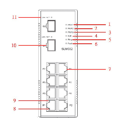
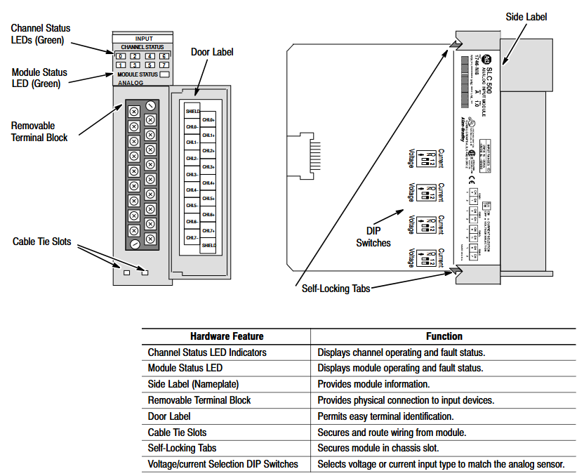
-The panel contains 9 green LED indicator lights: 8 channel status lights (corresponding to 8 input channels), 1 module status light, which intuitively displays the operation and fault status;

-Side mounted DIP switch for selecting channel input type (voltage/current).

System compatibility – supports two interface modes, Class 1 and Class 3:

-Class 1 (default): Suitable for SLC 500 fixed type, SLC 5/01/02/03/04 processors, occupying 8 output configuration words and 8 input data words;

-Class 3 (Advanced): Only compatible with SLC 5/02/03/04 processors, with additional support for user-defined scaling and channel status word monitoring, occupying 12 output configuration words and 16 input words (including 8 data words and 8 status words).

Key feature – Automatic calibration: All enabled channels undergo continuous temperature compensation and automatic calibration without the need for manual triggering;

-Fault diagnosis: supports fault detection such as open circuit, over range, and configuration errors, and provides feedback through LED and status words;

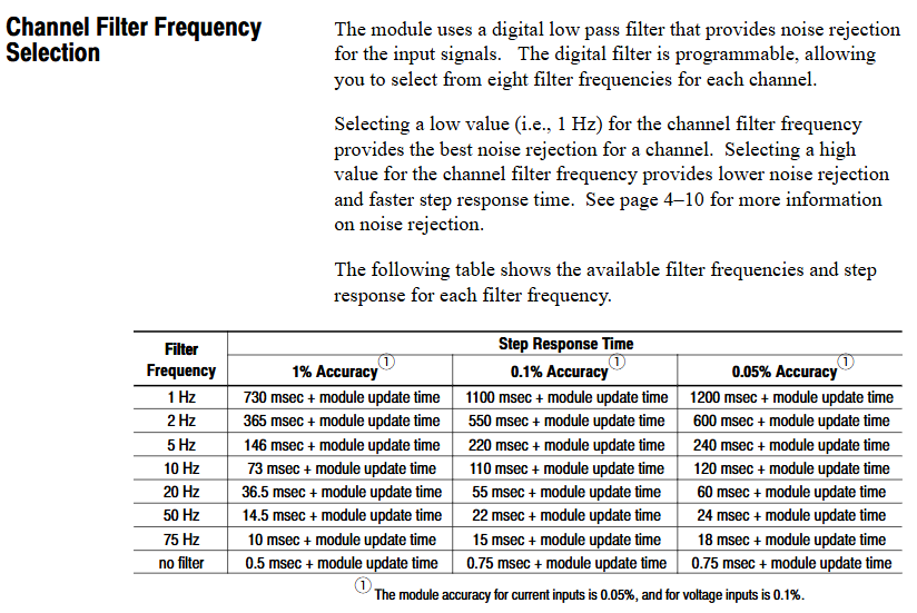
-Filtering function: Programmable digital low-pass filtering (8 frequencies to choose from), balancing noise suppression and response speed.

Quick Start Guide

For users with experience using SLC 500, a simplified deployment process is provided, with the following core steps:

Equipment preparation: Screwdrivers, analog input devices (such as sensors), shielded cables (recommended Belden 8761), SLC processors and power supplies, and programming equipment (such as RSLogix 500) need to be prepared.

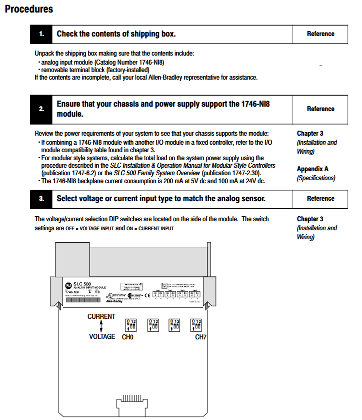
Hardware inspection: Confirm that the packaging contains 1746-NI8 modules and pre installed terminal blocks. If missing, please contact the supplier.

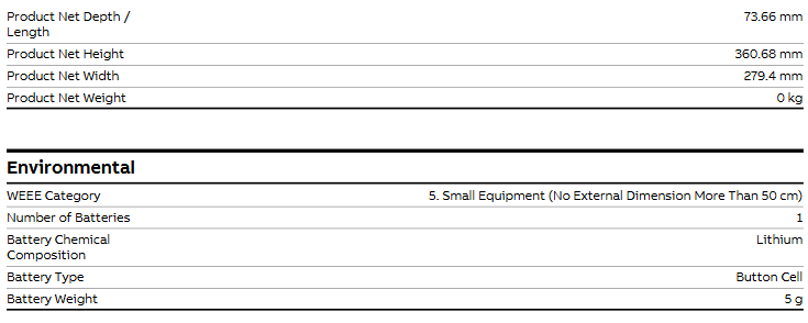
Power compatibility: The module is powered through the backplane and consumes 5V DC 200mA and 24V DC 100mA. It is necessary to ensure that the chassis power load is sufficient (refer to manual 1747-6.2 to calculate the total load).

DIP switch setting: Adjust the side DIP switch (OFF=voltage, ON=current) according to the input type (voltage/current).

Module installation: Insert the chassis into any non processor slot while powered off (it is recommended to install it in the rightmost slot in high-temperature environments for higher temperature tolerance), and tighten the self-locking buckle.

Wiring: Use shielded cables to connect the sensor to the terminal block. Single ended signals can be short circuited to the common terminal, while differential signals should pay attention to the common mode voltage (≤± 10.5V). The shielding layer should be grounded at one end (channels 0-3 should be connected to the top shielding terminal, and channels 4-7 should be connected to the bottom).

System configuration: Set the module ID code (3526 for Class 1 and 12726 for Class 3) through programming software. Class 3 requires an additional configuration of 16 input words and 12 output words.

Channel configuration: Define channel configuration words (such as input type, data format, filtering frequency) in the ladder program, and download them to the module output image area through the COPY instruction.

Startup verification: It is normal for the module status light and the enabled channel light to remain on after power on; If the light flashes or does not light up, refer to Chapter 7 for troubleshooting.

Installation and wiring

(1) Installation specifications

Static protection: Wear a grounding wristband during operation to avoid touching the back panel pins, and store in an anti-static bag when idle.

Slot selection:

Modular chassis: can be installed in any slot except slot 0 (processor slot);

Fixed expansion chassis (1746-A2): Please refer to the compatibility table (if combined with OB16 module, confirm current load), and some combinations require external power supply.

Temperature adaptation: The working temperature of the regular slot is 0-55 ℃, and the rightmost slot is 0-60 ℃. Avoid approaching high heating modules (such as 32 point I/O modules) or strong interference sources (such as frequency converters).

Installation steps: Align the upper and lower guide slots of the chassis, slowly push them into the buckle lock, and install the 1746-N2 filling plate in the idle slot.

(2) Wiring requirements

Specification for Wiring Types

The terminal block has 18 detachable terminals, including 2 shielded terminals, supporting up to 14 AWG wires, and terminal screw torque ≤ 5 lb in (0.565 Nm).

The single ended input signal is connected positively to CHx (+) and negatively to CHx (-), and the multi-channel common terminal can be short circuited to reduce wiring.

The common mode voltage of the differential input signal source should be ≤± 10.5V. It is forbidden to connect the common terminal of the signal source to the module to avoid grounding loops.

The power module does not provide sensor power and needs to be separately matched with a DC power supply of the transmitter specifications (such as 24V DC).

Run basic configuration

(1) Module identification and addressing

ID code setting: The corresponding ID code (Class 1:3526, Class 3:12726) needs to be entered in the programming software. Early versions of RSLogix 500 only supported Class 1 and need to be upgraded to v1.30+to support Class 3.

Memory Mapping:

Class 1: Output image O: e.0-O: e.7 consists of 8 channel configuration words, while input image I: e.0-I: e.7 consists of 8 channel data words;

Class 3: The output image contains an additional O: e.8-O: e.11 (2 sets of scaling upper and lower limits), and the input image I: e.8-I: e.15 consists of 8 channel status words.

(2) Key parameter calculation

Module update time: The total sampling conversion time for all enabled channels is 0.75ms for a single channel and 6.0ms for 8-channel full configuration (independent of filtering frequency).

Channel response time:

Start time (enable until status word update): 101-107ms;

Shutdown time (from disabled to data reset): 1-7ms;

Reconfigure time (modify configuration): 101-107ms (excluding data format modifications).

Filtering and Anti aliasing:

The filtering frequency determines the step response (such as achieving 1% accuracy in 730ms for 1Hz filtering, and only 0.5ms without filtering);

Aliasing frequency=1/(number of enabled channels x 0.00075), channel 1 is 1333Hz, and channel 8 is 167Hz. It is necessary to ensure that the signal frequency is lower than the aliasing frequency.

Channel configuration and data processing

(1) Detailed Explanation of Configuration Words

Each channel configuration word (16 bits) defines the channel working mode, and the key bits have the following meanings:

Description of Range Function Options

The voltage (± 10V/1-5V/0-5V/0-10V) and current (0-20mA/4-20mA/± 20mA/0-1mA) of the 0-2 input type should be consistent with the DIP switch

3-5 data format engineering unit (1mV/1 μ A step) Scaled-for-PID(0-16383)、 Proportional counting (-32768-32767), NI4 compatible format, Class 3 user-defined

6-7 open circuit state is only valid for 4-20mA, with optional zero value, upper limit value, and lower limit value

8-10 filtering frequency 000=no filtering, 001=75Hz, 010=50Hz, 011=20Hz, 100=10Hz, 101=5Hz, 110=2Hz, 111=1Hz

11 channel enable 1=enabled (participating in sampling), 0=disabled (data reset)

12-15 reservation needs to be set to 0

(2) Data scaling

The digital output of the module needs to be converted into actual engineering units (such as temperature and pressure), supporting multiple scaling methods. Examples are as follows:

Engineering unit: directly corresponding to physical quantities (such as 4-20mA corresponding to 100-500 ℃, data word 5500 → 247.5 ℃);

Scaled for PID: adapted to SLC PID instructions, 0 corresponds to lower limit, 16383 corresponds to upper limit (e.g. 4-20mA corresponds to 212-932 ° F, data word 5500 → 453.71 ° F);

User defined (Class 3): Set two sets of zoom ranges through O: e.8-O: e.11 and map them proportionally (e.g. 0-10V corresponds to 0-200psi, data word 16600 → 166psi).

(3) Status word monitoring (Class 3)

The input images I: e.8-I: e.15 are channel status words, and the key bits provide feedback on the operating status

Position 0-2: Current input type;

Position 3-5: Current data format;

Bit 11: Channel enable status (1=enabled);

Bit 12: Open circuit error (1=detected);

Bit 13: Over range error (1=input exceeds upper limit);

Bit 14: Under range error (1=input exceeds lower limit);

Bit 15: Configuration error (1=invalid configuration word).

Example of trapezoidal logic

Provide ladder diagram examples of typical programming scenarios, including:

Initialization configuration: Use the first scan bit (S: 1/15) to copy the preset configuration word (stored in the N10 file) to the module output image area (such as O: 3.0-O:3.7) through the COP instruction, and batch enable 8 channels.

PID interface: Set the channel data to Scaled for PID format and directly use it as a process variable (PV) for PID instructions without intermediate scaling (e.g. I: 3.0 → PID control block N11:23).

Fault alarm: Monitor the open circuit error bit of the Class 3 status word (such as I: 3.8/12), trigger the output point (such as O: 2.0) to drive the alarm light.

Diagnosis and troubleshooting

(1) LED status interpretation

Solution to the cause of module status light channel status light malfunction

Always on, always on. Normal operation without operation required

Constant flashing, open circuit/over range/configuration error 1. Check wiring and sensors; 2. Confirm that the configuration word is valid; 3. Check the status word to locate the error type

Extinguish module fault/not powered on 1. Check the power supply of the backplane; 2. Re plug and unplug the module; 3. Contact technical support

Constant on/off channel not enabled. Set bit 11=1 in the configuration word to enable channel

(2) Common troubleshooting

Open circuit error: Only 4-20mA channel, check for sensor disconnection, loose terminals, response time ≤ 6ms (8-channel full configuration).

Over range error: Input signal exceeds the configured type range (such as 4-20mA channel input<3.5mA or>20.5mA), calibrate sensor or adjust configuration.

Configuration error: The configuration word position setting is invalid (such as setting the data format to 110), and the configuration word needs to be redefined.

Noise interference: If the analog signal fluctuates greatly, check the shielding grounding, stay away from the power line, or reduce the filtering frequency (if set to 1Hz).

(3) Spare parts and support

Replaceable spare parts: terminal block (1746-RT25G), terminal cover (1746-R13), manual (1746-6.8);

Technical support: Module fault symptoms, LED status, image data, processor model and firmware version are required. Contact Allen Bradley customer service (Americas: 1-888-565-4155; Europe:+800-44444-8001; Asia:+86-400-842-8599).

Application examples

Provide two practical cases covering both basic and advanced scenarios:

Basic case: Monitoring single-phase motor current, 4-20mA signal corresponding to 0-100A, channel 0 set as engineering unit+10Hz filtering, program converts data into BCD format to drive LED display screen (TOD command required).

Advanced case: Multi parameter monitoring (three-phase motor current, tank pressure, liquid level), switching the display current phase sequence through a selection switch, triggering high and low level alarms when the liquid level exceeds the limit, and configuring different input types (current/voltage) for each of the 5 channels.

Rockwell 1746-IB32 Digital Input Module

Product basic positioning

Model attribution: 1746-IB32 is a digital input module of Rockwell Automation SLC 500 series programmable logic controller (PLC), mainly used for collecting discrete switch signals (such as on/off signals output by sensors, buttons, limit switches, etc.) in industrial sites, and converting them into digital signals recognizable by PLC to achieve real-time monitoring of equipment status.

Typical application scenarios: Widely used in manufacturing production lines, mechanical equipment control, process automation and other fields, such as assembly line workstation status detection, motor start stop signal acquisition, safety door switch status monitoring, etc.

Core technical specifications

(1) Input characteristics

Specification category reference parameter description

The single module supports 32 independent digital input channels and can simultaneously collect 32 switch signals. The channels are electrically isolated to avoid signal interference

The input signal type is direct current (DC), which usually supports two common industrial DC voltages: 24V DC or 120V DC (please refer to the official document for details), and is compatible with NPN or PNP sensor outputs

Input response time ≤ 1ms (typical value) to quickly respond to on-site signal changes, ensuring real-time control logic, suitable for scenarios with high response speed requirements

Low power design with input current of 7mA~10mA (per channel), reducing overall system energy consumption, and compatible with the output current range of most industrial sensors

(2) Electrical and Protection

Isolation method: Adopt channel to channel optoelectronic isolation or group isolation (such as isolation every 8/16 channels), with isolation voltage usually ≥ 250V AC (1 minute), effectively suppressing electromagnetic interference (EMI) and grounding loop problems in industrial sites.

Overvoltage/Overcurrent Protection: Some models have built-in overvoltage protection circuits (such as transient voltage suppressors TVS) and overcurrent protection (such as self recovery fuses) to prevent module damage from abnormal voltage/current on site.

(3) Physics and Installation

Dimensions: Suitable for SLC 500 series standard racks (such as 1746-A7/A10, etc.), usually designed as a “thin module”, with a width of about 32mm, a height matching the rack (about 100mm), and a depth of about 160mm (subject to official data), saving rack installation space.

Installation method: It is installed using DIN rails or directly fixed on the SLC 500 rack backplane. During installation, it is necessary to ensure that the module is reliably connected to the rack bus to ensure stable data transmission and power supply.

(4) Environmental adaptability

Working temperature: -20 ℃~60 ℃ (industrial standard), can operate stably in high and low temperature industrial environments, such as workshops, warehouses, outdoor control cabinets, and other scenarios.

Humidity range: 5%~95% RH (non condensing), suitable for humid environments, no additional moisture-proof measures required (requires overall protection of the control cabinet).

Protection level: The protection level of the module itself is usually IP20 (for panel installation), and it needs to be installed in a closed control cabinet to avoid direct contact with dust and liquids.

Functional characteristics (based on the commonality of SLC 500 series modules)

Diagnostic function: Supports channel level fault diagnosis, such as open circuit and short circuit detection. Diagnostic information can be read through PLC programming software (such as RSLogix 500) to quickly locate the faulty channel and reduce troubleshooting time.

Compatibility: Fully compatible with all SLC 500 series CPU modules (such as 1747-L511/L532, etc.), can be mixed with digital output modules (such as 1746-OB16) and analog modules (such as 1746-NI8) of the same series for installation, and build a complete control system.

Wiring method: Adopting a detachable terminal block (such as 1746-TB32 terminal board), supporting “front wiring” or “rear wiring”, the wiring operation is convenient, and the terminal block can be directly disassembled for later maintenance without dismantling the entire module.

Precautions for use

Power supply requirements: The module is powered by the SLC 500 rack backplane (usually a 5V DC logic power supply+24V DC input power supply). It is necessary to ensure that the rack power module (such as 1746-P2) outputs stably to avoid voltage fluctuations that may cause module failures.

Signal wiring: Input signal lines should be routed separately from power lines (such as motor cables) to reduce electromagnetic interference; When wiring for long distances (over 100m), shielded twisted pair cables should be selected and properly grounded.

Module address setting: If multiple modules of the same type are installed in the rack, a unique address needs to be set through the address dip switch on the module to ensure that the PLC can correctly identify each module channel.

Software configuration: In RSLogix 500, it is necessary to correctly configure the module type (select “1746-IB32”) and input filtering time (which can be set according to the on-site interference situation, such as 0.1ms~10ms) to avoid false triggering caused by high-frequency interference.

Emerson PACSystems ™  Ethernet Switch SLM082 

Product Core Overview 

(1) Product positioning

SLM082 is a powerful management industrial switch suitable for harsh industrial environments such as wide temperature, high dust, and humidity. It supports web, console (CLI), third-party SNMP software, and exclusive “PACSystems Ethernet Switch Configuration Tool” for management, and can configure multiple switches simultaneously and monitor their status.

(2) Software core functions

Specific description of functional categories

Network redundancy supports the world’s fastest redundant Ethernet ring (with a recovery time of less than 10ms when 250 devices are cascaded), enabling ring coupling and dual home topology; Compatible with RSTP (802.1w) Fast Spanning Tree Protocol

Network management supports the SNMP v1/v2/v3 protocol; Support VLAN partitioning based on port/802.1Q standards; Support LLDP (Link Layer Discovery Protocol) to automatically discover network node information

Event notifications can generate event alerts through email (SMTP), SNMP Trap, and relay output

Traffic control supports 802.1p Quality of Service (QoS) to ensure real-time traffic; Support IGMP Snooping multicast filtering to reduce network bandwidth usage

Security protection supports port enable/disable, MAC address based port security, 802.1x port authentication, and Radius centralized password management; SNPv3 encryption authentication

(3) Hardware core features

Power supply: Three redundant DC inputs.

Environmental adaptability: working temperature -40~70 ℃, storage temperature -40~85 ℃, working humidity 5%~95% (no condensation), protection level IP30.

Port configuration: 8 10/100Base-T (X) Ethernet ports (RJ45 interface), 2 100/1000Base-X SFP optical ports, and 1 Console port.

Physical dimensions: 52mm (width) x 106mm (depth) x 144mm (height).

Hardware Installation

SLM082 supports two installation methods to meet the needs of different industrial scenarios:

(1) DIN rail installation

The switch backplane comes with a DIN rail kit, which can be directly fastened to the standard DIN rail for fixation. The installation steps are simple and do not require additional drilling.

(2) Wall mounted installation

The packaging contains a wall mounted panel, which needs to be punched on the wall according to the dimensions indicated in the manual (such as aperture, hole spacing, etc.). After fixing the wall mounted panel with screws, the switch can be installed.

Hardware interface and indicator lights

(1) Front panel interface (Table 3.1)

Interface Type Quantity Function Description

10/100Base-T (X) ports with 8 RJ45 interfaces, supporting automatic negotiation (rate/duplex mode), default rate “automatic”, duplex “automatic”, flow control “disabled”

100/1000Base-X SFP ports with 2 optical ports, used to connect fiber optic modules and support high-speed data transmission

Console port with one RJ45 interface, connected to the computer via an RS-232 adapter cable for CLI management

Press the Reset button for 5 seconds to restore the switch to factory settings

(2) Meaning of front panel indicator lights (Table 3.2)

LED identification color status description

The green constant light of PW1/PW2/PW3 corresponds to the activated power supply module (PW1/PW2) or power interface (PW3)

R. The M (Ring Master) green constant light switch is the master node (Ring Master) of the redundant ring

The redundant ring with green constant brightness has been enabled;

Slow flashing: Redundant ring topology abnormality;

Flash: Redundant ring is working normally

Fault: The yellow light is constantly on, indicating a power failure or port interruption/malfunction

10/100Base-T (X) port LNK/ACT green constant light: port link established;

Flashing: The port is transmitting data and the link and activity status of the corresponding Ethernet port

10/100Base-T (X) port Full Duplex yellow constant light port works in full duplex mode

SFP port LNK/ACT green/yellow constant light: optical port link established;

Blinking: The optical port is transmitting data, and the corresponding link and activity status of the optical port are flashing

(3) Top panel component

Terminal block: includes PW1/PW2 (12-48V DC power input) and relay output interfaces( 1A@24VDC ).

Power interface (PW3): 12-45V DC power input socket.

Reset button: Press for 3 seconds to reset the device, press for 5 seconds to restore factory settings.

Console port: RJ45 interface, used for CLI management connection.

Cable Configuration

(1) Ethernet cable

Applicable standards: 10BASE-T supports Category 3/4/5 unshielded twisted pair (UTP), while 100BASE-TX requires Category 5 UTP.

Maximum transmission distance: Both are 100m (328 feet), with RJ45 connectors.

Pin definition: In 100BASE-TX/10BASE-T cables, pins 1/2 are used for sending data and pins 3/6 are used for receiving data; Supports automatic MDI/MDI-X functionality, allowing for direct connection between computers and switches (without the need for crossovers).

(2) SFP optical module and fiber optic

Optical module type: Supports multi-mode (transmission distance 0-550m, wavelength 850nm, fiber specifications 50/125 μ m or 62.5/125 μ m) and single-mode SFP modules, with LC connectors.

Connection rule: The TX port of switch A needs to be connected to the RX port of switch B to ensure the correct transmission of optical signals.

(3) Console cable

Cable specifications: The package contains a DB-9 (female) to RJ45 cable, which is used to connect the computer COM port to the switch Console port.

Pin correspondence: Pin 2 (RD, receive data) of the computer end (DB-9 male head) corresponds to Pin 2 (TD, send data) of the DB-9 female head, Pin 3 (TD, send data) corresponds to Pin 3 (RD, receive data) of the female head, and Pin 5 (GD, ground) corresponds to Pin 5 (GD, ground) of the female head.

Web Management Configuration 

Web management is based on the built-in HTML web pages (Flash storage) of the switch, supporting IE5.0 and above browsers (with Java Applets network port permissions enabled), and compatible with both HTTP and HTTPS modes.

(1) Login preparation and default parameters

Default parameters: IP address 192.168.0.100, subnet mask 255.255.255.0, default gateway 192.168.0.254, username/password “admin”.

Login steps: Open the browser and enter “http:///device IP” or “https://device IP”. Enter the username and password to enter the management interface.

(2) Core configuration function

1. Basic Settings (5.1.5)

Switch information: System name (maximum 64 bytes), physical location, contacts, firmware version (default 1.03), kernel version (default v2.49), device MAC address, etc. can be modified.

Administrator password: Old username/password verification is required, and the new password must be at least 8 characters long, containing 1 uppercase letter, 1 number, and 1 special character (such as @ # $).

IP configuration: You can manually set IP/subnet mask/gateway/DNS, or enable DHCP clients to automatically obtain IP (if there is a DHCP server in the network).

SNTP time synchronization: After enabling the SNTP client, you can set the time zone (such as GMT Greenwich Mean Time), SNTP server IP, and support daylight saving time configuration (setting start and end times and offsets).

2. Backup and Upgrade (5.1.6)

Configure backup/restore: Back up the current configuration file (such as data.bin) through the TFTP server, or restore the configuration from the TFTP server.

Firmware upgrade: Prepare a TFTP server and store firmware files (such as image. bin). Enter the server IP and file name in the interface, click “Upgrade” to complete the upgrade (power off is prohibited during the upgrade, and the physical loop must be removed first).

3. DHCP Server (5.1.7)

Function switch: When enabled, the switch acts as a DHCP server and can assign dynamic IP addresses to LAN devices.

Parameter configuration: Set IP allocation range (such as 192.168.0.2-192.168.0.200), subnet mask, gateway DNS, And the IP lease duration (default 168 hours).

Port IP binding: A fixed IP can be assigned to a specified port to ensure that the device obtains the same IP every time it connects.

4. Port settings (5.1.8)

Port control: Set port enable/disable, rate/duplex mode (such as auto negotiation, 100 full), flow control mode (symmetric/asymmetric), and port security (only allow MAC addresses in the security list to forward data when enabled).

Rate limit: It can limit the inbound/outbound traffic of ports and support classification restrictions based on “broadcast frames”, “broadcast+multicast frames”, and “broadcast+multicast+flood unicast frames”.

Trunk port aggregation: supports static aggregation or 802.3ad LACP dynamic aggregation, merging multiple physical ports into logical links to improve bandwidth; The number of active ports in the aggregation group can be set, and the backup port will be automatically activated in case of failure.

5. Network redundancy (5.1.9)

Redundant Ring: Supports three topologies: ring, ring coupling, and dual homing. It requires specifying the “Ring Master”, “First Ring Port”, and “Second Ring Port”; Ring coupling is used to split a large ring into two small rings, reducing the impact of topological changes; Dual attribution is used to connect redundant rings and backbone switches through RSTP links.

RSTP configuration: After enabling RSTP, the bridge priority (0-61440, a multiple of 4096, with higher priority for smaller values), maximum aging time (6-40 seconds), Hello time (1-10 seconds), and forwarding delay (4-30 seconds) can be set, satisfying the formula “2 × (forwarding delay -1) ≥ maximum aging time ≥ 2 × (Hello time+1)”.

6. VLAN configuration (5.1.10)

802.1Q Tag VLAN: Based on the IEEE 802.1Q standard, cross vendor switch VLAN partitioning is achieved by inserting VLAN tags (VID) into Ethernet frames, supporting GVRP protocol automatic synchronization of VLAN configuration; By default, all ports belong to the default VLAN with VID=1 (which cannot be deleted). Ports can be set to Access (only carrying untagged frames), Trunk (only carrying tagged frames), or Hybrid (simultaneously carrying two types of frames) modes.

Port based VLAN: Logical networks are divided by ports, and only members of the same VLAN can exchange data. Ports that are not selected are automatically assigned to another VLAN; Ignore VLAN tags when enabled.

​7. Traffic priority (5.1.12)

QoS strategy: Supports “strict priority” (high priority queue data is transmitted first until empty) or “8:4:2:1 weighted fair queue” (proportionally transmitting high/medium/low/lowest priority queue data).

Priority classification:

Port based: Assign a priority level of “high/medium/low/lowest” to each port.

Based on COS/802.1p: Map to level 4 queue according to the 802.1p field values (0-7) in the frame.

Based on TOS/DSCP: Map to level 4 queue according to the TOS/DSCP field values (0-63) in the IP header.

8. Security Configuration (5.1.14)

IP Security: Only allow IPs in the ‘Secure IP List’ to manage switches through Web/SNMP.

Port security: After enabling, the port is prohibited from learning new MAC addresses and only forwards MAC frames from the security list.

MAC blacklist: Discard frames with target MAC addresses in the blacklist to prevent specific devices from receiving data.

802.1x authentication: Radius server IP, authentication port (default 1812), billing port (default 1813), shared key, etc. need to be configured, supporting four authorization modes: port “Accept”, “Reject”, “Authorize”, and “Disable”.

9. Alarm and Monitoring (5.1.15-5.1.17)

System alarms: Supports SYSLOG (local/remote server logs), SMTP email alarms, and can be triggered by events such as “system cold start”, “power status”, “SNMP authentication failure”, “redundant ring topology change”, etc; The fault relay is triggered synchronously when an alarm is triggered, and the Fault LED is constantly on.

Status monitoring: View MAC address table (dynamic/static entries, support aging time setting), port statistics (data volume, error frames, etc.), system event logs (can be refreshed/cleared), port mirroring (copy source port TX/RX data to target port monitoring).

GE IC695CRU320 redundant control unit

Product basic information

Product model: IC695CRU320

Product Name: Redundant Control Unit, belonging to GE Fanuc RX3i series programmable logic controllers (PLCs). Its core function is to provide dual machine redundant backup for PLC systems, ensuring seamless switching of backup controllers in case of main controller failure and avoiding system shutdown.

Document source: Product specifications and application manual published by NEX Instrument, focusing on hardware parameters, redundant logic, installation configuration, and compatibility instructions.

Core functions and redundancy principles

(1) Core functions

Dual machine redundant backup

Support two RX3i controllers (such as IC695CPU315/330, etc.) to form a primary and backup architecture, and achieve hardware level redundant control through IC695CPU320.

When the main controller is running normally, the backup controller synchronizes the program, data, and I/O status of the main controller in real time; When the main controller fails (such as power outage or hardware failure), the backup controller switches to the main control mode without disturbance, with a switching time of ≤ 100ms, to ensure continuous production process.

Status monitoring and diagnosis

Built in redundant status indicator lights (such as primary and backup status, synchronization status, fault alarm), visually display the operating status of the redundant system.

Support reading redundant system diagnostic information through RX3i programming software (such as Proficy Machine Edition), including switching reasons, synchronization anomalies, hardware failures, etc., for easy fault location and troubleshooting.

Flexible redundant configuration

Support the “Hot Standby” mode, where both the primary and backup controllers are powered on and running, and the backup devices are in a “ready” state instead of standby mode, improving switching speed.

Can be used with RX3i series I/O modules and communication modules, compatible with redundant I/O architectures (such as IC695RIO remote I/O modules), achieving full system redundancy coverage.

Technical specifications

(1) Hardware parameters

Specification category specific parameters

Power supply requirement input voltage:+5V DC (powered by the RX3i rack backplane, no external independent power supply required); Power consumption: ≤ 5W

Physical dimension width: 40mm (1.57 inches); Height: 100mm (3.94 inches); Depth: 160mm (6.30 inches), compatible with RX3i standard rack (such as IC695CHS012/024)

Working temperature: 0 ° C~60 ° C (operating state); -40 ° C~85 ° C (storage state)

Humidity range 5%~95% RH (non condensing, compliant with IEC 61131-2 environmental standards)

Protection level IP20 (panel installation, to be used in conjunction with control cabinet to prevent dust and liquid intrusion)

(2) Redundancy performance indicators

Performance category indicator requirements

Switching time between primary and backup: ≤ 100ms (from main controller fault detection to backup controller taking over control)

Real time data synchronization in synchronization mode (including program memory, data memory, I/O image area), with a synchronization rate of ≥ 100Mbps

Fault detection range: main controller power failure, CPU hardware failure, memory error, communication link interruption (synchronous link between main and backup)

Redundant links with built-in 2-channel high-speed synchronization interfaces (for data exchange between primary and backup controllers), supporting fiber optic or shielded twisted pair connections

Hardware composition and interfaces

(1) Hardware composition

IC695CRU320 is an independent module structure, with core components including:

Redundant control chip: responsible for determining the primary and backup status, synchronizing logic control, and triggering switching;

Synchronous communication interface: 2 RJ45 or optical ports (depending on configuration), used for data synchronization between the primary and backup controllers;

Status indicator panel: 4 LED indicator lights, meaning as follows:

RUN (green): The redundant unit is running normally;

MASTER (red): The currently connected controller is in main control mode;

STANDBY (yellow): The currently connected controller is in standby mode;

Fault (red): Redundant system failure (such as synchronization failure, module hardware error).

(2) Key interfaces

Interface Type Quantity Function Description

One rack backplane interface is inserted into the RX3i standard rack (such as IC695CHS012) and connected to the rack backplane bus to obtain power and exchange data

Two synchronous communication interfaces are connected to the main and backup controllers to achieve real-time data synchronization (supporting maximum transmission distance: 100m twisted pair cable, 2km fiber optic cable)

One reserved RS232 or Ethernet interface (some versions) for diagnostic equipment to read redundant logs

Installation and configuration requirements

(1) Installation conditions

Rack compatibility

Only compatible with RX3i series standard racks, such as IC695CHS012 (12 slots) and IC695CHS024 (24 slots), which need to be installed in the “redundant control unit dedicated slot” of the rack (usually slots 1-2 on the left side of the rack, refer to the rack manual for details).

Controller compatibility

The primary and backup controllers must be RX3i CPU modules of the same model, supporting models including IC695CPU315, IC695CPU330, IC695CPU340, and the CPU firmware version must be consistent (recommended V3.0 and above).

Environmental Requirements

The installation environment should be kept away from strong electromagnetic interference (such as frequency converters, high-power motors), and avoid sudden temperature changes or dusty/humid environments;

Reserve a heat dissipation space of ≥ 50mm around the module to ensure good heat dissipation (without forced air cooling, the ambient temperature does not exceed 55 ° C).

(2) Configuration steps

Hardware Installation

Insert IC695CRU320 into the dedicated slot of RX3i rack and tighten the panel screws;

Connect the synchronization interface between IC695CRU320 and the main and backup controllers using a synchronous cable (twisted pair or fiber optic);

Connect the power supply, I/O module, and communication module separately for the primary and backup controllers (ensuring consistent configuration of primary and backup I/O).

Software configuration (via Proficy Machine Edition)

Create a new RX3i redundancy project, select the “dual machine redundancy” architecture, specify the primary and backup CPU models and IC695CRU320 as redundant control units;

Configure synchronization parameters (such as synchronization rate, timeout) to enable the “automatic switching” function;

Download the program to the main controller, and the software will automatically trigger the synchronization of primary and backup data. After the synchronization is completed, the redundant system will enter the “normal operation” state.

Compatibility and selection suggestions

(1) List of compatible hardware

Example of compatible device types and models

RX3i Controller IC695CPU315 (Compact), IC695CPU330 (Standard), IC695CPU340 (High Performance)

RX3i rack IC695CHS012 (12 slots), IC695CHS024 (24 slots), IC695CHS008 (8 slots, small system)

Redundant I/O modules IC695RIO001 (remote I/O adapter), IC695RIO002 (redundant I/O interface module)

Communication modules IC695ETM001 (Ethernet module), IC695COM001 (RS485 module)

(2) Selection suggestions

Applicable scenarios

Industrial scenarios that require continuous operation, such as chemical production lines, power dispatch systems, water treatment equipment, etc., require a system availability requirement of ≥ 99.99%.

Selection precautions

The primary and backup controllers need to be completely consistent (model, firmware version, memory configuration) to avoid synchronization failure due to hardware differences;

If the system includes remote I/O, redundant I/O modules (such as IC695RIO002) should be used to ensure that the I/O layer also has redundancy capability;

It is recommended to use shielded twisted pair cables (short distance, ≤ 100m) or multimode optical fibers (long distance, ≤ 2km) for synchronous cables to reduce synchronization anomalies caused by interference.

Troubleshooting and Maintenance

(1) Common faults and solutions

Possible causes and solutions for the fault phenomenon

The redundant status light “FAULT” is always on. 1. The synchronization link between the primary and backup controllers is interrupted; 2. The firmware versions of the primary and backup CPUs are inconsistent; 3. CRU module hardware failure: 1. Check the synchronization cable connection and replace the faulty cable; 2. Upgrade the primary and backup CPUs to the same firmware version; 3. Replace the IC695CRU320 module

Primary/backup switching failure: 1. Backup controller data synchronization is not completed; 2. The switch enable is not turned on; 3. Inconsistent I/O configuration: 1. Wait for synchronization to complete (the synchronization light is always on to indicate completion); 2. Enable “automatic switching” in the software; 3. Verify the primary and backup I/O configurations to ensure consistency

The backup controller cannot synchronize. 1. Poor contact of the synchronization interface; 2. Memory error in the main controller; 3. CRU synchronization logic fault 1. Re plug and unplug the synchronization cable, clean the interface; 2. Restart the main controller and check the memory status; 3. Reset CRU module (via software or power off restart)

(2) Daily maintenance suggestions

Regularly (every 3 months) check the redundancy status indicator lights to confirm that the primary and backup are running normally and the synchronization link is normal;

Export redundant system diagnostic logs through Proficy Machine Edition every 6 months to analyze potential risks such as frequent synchronization failures and switching records;

Avoid plugging and unplugging CRU modules or synchronous cables while they are live to prevent hardware damage; When replacing modules, power off first to ensure that the primary and backup controllers are in a “stop” state.

Bently 3500/15 AC and DC power modules

Product basic information

Product Name: 3500/15 AC and DC Power Supplies

Brand: Bently Nevada, under Baker Hughes, used for mechanical equipment condition monitoring systems

Document Information: Technical Data Sheet for Model 141530 Rev. N

Core functions and installation features of the product

(1) Module positioning and redundancy design

Physical specifications: It is a half height module and must be installed in the designated slot on the left side of the rack.

Redundant configuration: The 3500 rack can install one or two power modules (AC and DC can be combined arbitrarily), and a single power module can supply power to the entire rack; If two are installed, the main power supply in the lower slot and the backup power supply in the upper slot can be seamlessly switched in case of a main power failure.

Hot swappable feature: As long as two power modules are installed in the rack, plugging or unplugging either module will not interrupt the rack operation.

(2) Power type and compatibility

Available power types: The 3500 series mechanical protection system supports three power options, as follows:

Universal AC Power

High Voltage DC Power Supply

Low Voltage DC Power Supply

Compatibility limitations:

Universal AC power supply and power input module (PIM) are not compatible with traditional 3500 AC power supply, high-voltage AC PIM, and low-voltage AC PIM.

High voltage DC and low-voltage DC power supplies and their corresponding PIMs are not compatible with traditional 3500 high-voltage/low-voltage DC power supplies and PIMs.

Technical specifications

(1) Input parameters

There are differences in input voltage, frequency, and other parameters among the three types of power supplies, as shown in the table below:

Power type Input voltage range Input frequency Other instructions

Universal AC power supply rated at 110-220 Vac;

Non hazardous area: 85-264 Vac rms;

Dangerous area: 85-250 Vac rms;

Peak value of 120-373 Vac pk 47-63 Hz needs to be used with universal AC PIM

High voltage DC power supply 88-140 Vdc – needs to be used with high voltage DC PIM

Low voltage DC power supply 20-30 Vdc – needs to be used with low voltage DC PIM

Additional notes

Voltage protection: Among all power options, undervoltage will not damage the power supply or PIM; Overvoltage can cause the fuse on PIM to melt.

Full rack current: Universal AC maximum 2.8 A rms; High voltage DC maximum 2.5 A; low voltage DC maximum 11.0 A.

(2) Output and indicator lights

Output function: Convert the input wide range voltage into a voltage that can be used by other 3500 modules.

Front panel indicator light (Supply OK LED): When the power module is working properly, the indicator light is on.

(3) Physical dimensions and weight

Module type, size (width x height x depth), weight

Power module 120.7 mm × 50.8 mm × 251.5 mm (4.75 in × 2.0 in × 9.9 in) 1.39 kg (3.06 lb)

Power Input Module (PIM) 120.7 mm × 25.4 mm × 114.3 mm (4.75 in × 1.0 in × 4.5 in) 0.34 kg (0.75 lb)

(4) Rack space requirements

Power module: It needs to occupy two half height slots on the left side of the rack, each slot can accommodate one power module, and supports the installation of two at the same time to achieve redundant power supply.

Power input module: It is a special half height module that is directly installed behind the corresponding power module.

Environmental and Compliance Certification

(1) Environmental restrictions

Range of environmental parameters

Working temperature -30 ° C to+65 ° C (-22 ° F to+150 ° F)

Storage temperature -40 ° C to+85 ° C (-40 ° F to+185 ° F)

Humidity 95%, no condensation

(2) Compliance and Certification

FCC certification: Complies with Part 15 of the FCC rules and meets two conditions: does not cause harmful interference; Any received interference (including interference that may cause unexpected operation) must be accepted.

EMC (Electromagnetic Compatibility):

Compliant with the EU EMC Directive 2014/30/EU.

Following standards: EN 61000-6-2 (industrial environment immunity), EN 61000-6-4 (industrial environment emission).

Electrical safety:

Compliant with the EU Low Voltage Directive 2014/35/EU.

Follow standard: EN 61010-1.

RoHS certification: Compliant with the EU RoHS Directive 2011/65/EU.

Maritime certification:

DNV GL: Classification rules for ships, offshore installations, and high-speed light vessels.

American Bureau of Shipping (ABS): Classification Criteria Rules Part 1 (Rules for Steel Ships, Rules for Offshore Installations and Structures).

Hazardous Area Certification:

CNRTLus: Class I Zone 2, AEx/Ex nA nC ic IIC T4 Gc; Class I, Zone 2, AEx/Ex ec nC ic IIC T4 Gc; Class I, Zone 2, Groups A, B, C, and D; The ambient temperature Ta is from -20 ° C to+65 ° C (-4 ° F to+149 ° F), and it needs to be installed according to drawing 149243 or 149244.

ATEX/IECEx:II 3 G,Ex nA nC ic IIC T4 Gc; Ex ec nC ic IIC T4 Gc; The ambient temperature Ta is from -20 ° C to+65 ° C (-4 ° F to+149 ° F), and it needs to be installed according to drawing 149243 or 149244.

Ordering and spare parts information

(1) Order coding rules

The ordering code format for the 3500/15 power module is “3500/15-AA-BB-CC”, and the meanings of each field are as follows:

AA (Top Slot Power Type): Includes traditional high voltage DC (88-140 Vdc), traditional low voltage DC (20-30 Vdc), universal AC (85-264 Vac rms), high voltage DC power supply, low voltage DC power supply, None.

BB (bottom slot power type): The options are the same as AA.

CC (Institutional Certification): 00 (No Certification), 01 (CSA/NRTL/C, Class I, Zone 2).

(2) Main spare parts list

Spare part number, spare part description

04310251, Universal AC Power Input Module; Power input cover screws (2 pieces/set)

129767, traditional high-voltage DC power input module; 3500/15 Power Module User Guide

118M0915-01、 Traditional high-voltage direct current power module; Replace the connector of the universal AC power input module

118M0915-02、 Traditional low-voltage DC power input module; Traditional low-voltage DC power module; Replace the connector of the DC power input module

129M0198、 High voltage direct current PIM; Low voltage DC PIM; High voltage DC power PIM (power input module) fuse replacement

-(unspecified number) Universal replacement of fuses for AC power input module and traditional high-voltage DC power input module; Universal replacement fuse for low-voltage DC power input module and traditional low-voltage DC power module (6.3 × 32 mm, fast melting type, 5A/500 Vac); Blank front panel of power module (including screws, 1 piece/set); Rear input connector cover of power module (1 piece/set, requires separate order of 04310251 screws)

Horner APG HE693CALKIT simulation module

Product Introduction

(1) Product Features

Horner APG HE693CALKIT calibration software is a computer program designed to support on-site and factory calibration of specific Horner APG simulation modules.

(2) Package composition

Each set includes: a floppy disk with calibration software, an RS-232 9-pin serial cable, a TTL to RS-232 converter, and an RS-232 ribbon cable with a 10 pin plug.

(3) Software operation requirements

Operating environment: Requires running on an IBM or compatible computer using DOS 3.1 or higher.

Hardware requirements: A text display is required and a serial port (COM1 or COM2) is used. The program defaults to using COM1.

(4) Module connection and preparation

The simulation module needs to be connected to the selected serial port on the computer through an RS-232 cable, combined with a TTL-to-RS-232 converter or an RS-232 ribbon cable with a 10 pin plug (depending on the simulation module to be calibrated).

The module does not need to be configured in the PLC, but appropriate power must be provided for the bus pins of the module.

Set conditions

(1) General Requirements (2.1)

Module installation: The module to be calibrated must be inserted into the PLC it will be used in the application; When inserting, the PLC must be powered off. After the module is correctly inserted into the PLC rack, the rack should be installed vertically (see Figure 1) to ensure good ventilation of the module; The PLC must be in ‘stop’ mode.

Stabilization time: After inserting the module into the PLC and completing the calibration connection, it needs to stabilize for at least 15 minutes after power on to ensure appropriate temperature balance.

Environmental requirements: Do not expose any equipment involved in the module or calibration process to extreme temperature changes; Calibration can be performed using an expansion rack.

(2) Set up process (2.2)

No additional special steps are required, and it should be carried out in conjunction with equipment preparation and module specific conditions.

(3) Equipment Requirements (2.3)

Calibrator: High quality calibrators (such as Omega CL511) must be used, and their accuracy must be more than twice that of the module (for example, THM884 has an accuracy of ± 1 degree Celsius, and the calibrator accuracy must be at least ± 0.5 degrees Celsius); It is recommended that all Horner Electric simulation modules use battery powered calibrators. When calibrating any thermocouple module, a battery powered calibrator must be used.

Wire requirements: The wire used for calibration must be the same as the wire used in the application, and must be of high quality with the shortest possible length; Avoid exposing wires to excessive radio frequency (RF) or electromagnetic interference (EMI) during the calibration process to prevent introducing errors.

(4) Module specific conditions (2.4)

1. Analog input module (2.4.1)

Covering HE693ADC406, HE693ADC405, HE693ADC415, HE693ADC410, HE693ADC420, the general requirements are as follows:

Calibrator: More than twice the accuracy of the module and powered by batteries.

Wire: Use high-quality wire that is the same as the wire used in the application and has the shortest length.

Environment: Avoid exposing the module to excessive EMI or RF, extreme temperature changes.

Installation and status: The module needs to be inserted into the PLC slot used in the application, and after being powered on and connected, it should be stable for at least 15 minutes. It should be installed vertically (in the panel installation position), and the PLC should be in “stop” mode; The unused channels during the calibration process of HE693ADC406 need to be short circuited and grounded.

2. Analog output module (2.4.2)

Regarding HE693DAC410 and HE693DAC420, it is required to be consistent with the analog input module (except for the channel short-circuit grounding of HE693ADC406).

3. Resistance Temperature Detector (RTD) module (2.4.3)

Including HE693RTD600, HE693RTD601, HE693RTD660, HE693RTD665, HE693RTD666, in addition to meeting the general requirements of the analog input module, there are additional requirements: unused channels during calibration must be short circuited and grounded; Modules with a suffix of -20 need to use the a=d switch (PT100D) in the calibration software.

4. Strain gauge module (2.4.4)

Including HE693STG883 and HE693STG884, it is required to be consistent with the RTD module (without using channel short-circuit grounding).

5. Thermocouple module (2.4.5)

Covering multiple models such as HE697THM160 and HE693THM166, in addition to meeting the general requirements for analog input modules, there are additional requirements: modules with a suffix of -21 need to use external ISOBLK for cold end compensation; During the calibration process, the last channel needs to be short circuited and grounded to optimize cold end compensation; Modules with suffix -02 need to use the “=k” switch in the executable file (refer to section 4.1).

Calibration process

(1) General Instructions (3.1)

The general calibration process is only a basic framework, with slight differences in the calibration process of each module, but the core logic is consistent. The simulation module needs to be calibrated according to the specific process described in the subsequent sections; Table 3.1 lists the simulation modules and their corresponding calibration files, with some corresponding relationships as follows:

Product model calibration software Product model calibration software

HE693ADC405 adc4x5.exe HE693THM166 thm166.exe

HE693ADC410、HE693ADC420 adciso.exe HE693THM665、HE693THM666、HE693THM668 thm668.exe

HE693ADC406 adc406.exe HE693THM884(REV. A,B,C) thm884_1.exe

HE693DAC410、HE693DAC420 daciso.exe HE693THM884(REV. D,E,F,G,H,HX,J,K,L) thm884_2.exe、THM884cal.exe(Windows  Version)

(2) Software startup (3.2)

1. Startup steps

Select the corresponding executable file from the floppy disk list (for example, calibrate HE693THM884 and select Thm884. exe).

Enter the corresponding command at the DOS prompt to run the calibration program: when using the COM1 port by default, enter “Thm884” and press “ENTER”; When using the COM2 port, enter “Thm884=C2” and press “ENTER”.

To view command line switches and their instructions, enter “Thm884=?” at the DOS prompt and press “ENTER”.

2. Screen Example (3.2.1)

After the program starts, the top of the screen will display the program name and version. Taking the THM884 thermocouple module calibrator (V2.04) as an example, the screen will display channel values, types, scales, zero points, and other information, as well as module models, channel quantities, hardware alarms, versions, and other parameters. At the same time, it will prompt the functions of each function key (F1-F9, Esc) (such as F1 calibration of J-type thermocouples, Esc exit, etc.).

3. Windows version software installation and operation (3.2.2, 3.2.3)

Installation: Load the floppy disk containing the THM884cal.exe (Windows version) installation file, locate and select the setup. exe file, follow the prompts to select the application file storage directory, and after installation is complete, you can use it.

Run: Find THM884cal.exe in the directory specified during installation, double-click the file to open the application; This version operates similarly to the DOS version. If you have any questions about the functionality, press the F12 key to access the help file.

(3) Process Overview (3.3)

Disable non-volatile random access memory (NVRAM): If the “disable” option is not provided, it will be automatically disabled. This step closes the old calibration constant and uses the default value for new calibration. The module needs to be reset to use the default value.

Disable PLC configuration: Make the module use default values (the module defaults to PLC configuration mode when powered on).

Initialization module: Execute after disabling PLC configuration.

Perform calibration: If it is a thermocouple module, you need to first select the calibration type. The software will prompt you for each step in the calibration process, and you need to follow the prompts.

Update NVRAM: Update the new default values to NVRAM.

Activate NVRAM: Enable the module to use the stored calibration constants the next time it is powered on.

Re initialize the module: Let the module re read the calibration and filtering constants from the NVRAM.

(4) Module specific calibration process (3.4)

The calibration steps and corresponding function keys for each module are as follows (some module examples):

1. Analog input module (3.4.1)

Taking HE693ADC406, HE693ADC405/415, and HE693ADC410/420 as examples:

Step Process Function Key

1. Disable NVRAM F5

Initialization module F6

3. Disable PLC configuration F8

Perform calibration (follow software prompts) F1

5 Update NVRAM (store new constants, select “Yes”) F3

Activate NVRAM F4

7 Initialization module F6

2. Analog output module (3.4.2)

The calibration steps for HE693DAC410 and HE693DAC420 are the same as those for the analog input module. It should be noted that when calibrating the analog output module, the PLC must be in non operating mode.

3. RTD module (3.4.3)

HE693RTD600 and other models:

Step Process Function Key

1. Disable NVRAM F7

Initialization module F6

3. Disable PLC configuration F8

Perform calibration (follow software prompts) F1, F2, F3

5. Update NVRAM (store new constants, select “Yes”) F5

Activate NVRAM F7

7 Initialization module F6

4. Strain gauge module (3.4.4)

The calibration steps for HE693STG883 and HE693STG884 are the same as those for the analog input module.

5. Thermocouple module (3.4.5-3.4.7)

HE697THM160, HE697THM260: Follow the same steps as the RTD module.

HE693THM166: The steps are consistent with the analog input module.

HE693THM406 and other models: The steps are consistent with the RTD module.

HE693THM884 (K-type+channel offset calibration): Use THM884_K.bat batch file, consisting of 15 steps, including module installation, power on, NVRAM disable/activate, PLC configuration disable/enable, calibration execution, offset setting and transmission, NVRAM update, module initialization, etc. Some steps require the use of function keys such as F1, F4, F5, F6, F7, F8, and finally remove the module after power off.

HE693THM894 (K-type calibration): Use the THM894_K.bat batch file, following the same steps as HE693THM884 (K-type+channel offset calibration).

Switch settings

(1) Switch Description (4.1)

Many simulation modules can be temporarily configured and software switches can be used, such as observing the reaction of thermocouple modules using T-shaped thermocouple wires (rather than the commonly used J, E, R types); Please note that the=T,=K, and=C switches are volatile and will not cause permanent changes to the module, while commands such as=NVRAM (such as=S) will cause permanent changes. The switch format is “Thm884 [=C1] [=C2] [=T] [=K] [=Snnnn. n, nnnn. n, nnnn. n,…]”, and the functions of each switch are as follows:

Switch Function Description

=C is used to select serial ports, for example=C1 (COM1),=C2 (COM2)

=T represents test mode, still transmitting command messages, but variables use internal values, receiving messages generated by simulation (software simulation mode), without the need to connect modules

=K sets the calibration type to K instead of the default J type

=Set calibration scale points for S, separated by commas (without spaces), in the order of K (or J) median, K high value, E median, E high value, R median, and R high value; When the value is 0, use the default value; If there are less than 6 entries, the remaining entries will use default values; The scale point must not be lower than 25 degrees Celsius (this low-temperature calibration point is crucial for optimizing cold end compensation)

(2) Example (4.2)

Command function

Thm884=C1 specifies COM1 as the serial port (default port)

Thm884=C2 specifies COM2 as the serial port (this command needs to be called to use COM2)

Thm884=T Enable test mode, transmit commands but only simulate messages, do not store values

Thm884=K sets the calibration type to K type (default J type), suitable for special applications and European calibration

Thm884 =S600.0,700 

ABB INNPM22 Network Processor Module

Basic product information

Core identification

Product ID: INNPM22

ABB model name: INNPM22

Product catalog description: INNPM22, Network Processor Module, suitable for Infinet systems

Product type: Communication-Module

Procurement and Customs Information

HS code: 851762 (classification description: telephone, including telephone for cellular or other wireless networks; other devices used for transmitting or receiving voice, image or other data, including wired or wireless network (such as local area network or wide area network) communication devices, but excluding transmission or reception devices of heading 84.43, 85.25, 85.27 or 85.28; Among them, machines used for receiving, converting, transmitting or reproducing voice, image or other data, including switching and routing devices, belong to the category of “other devices used for transmitting or receiving voice, image or other data, including wired or wireless network communication devices”

Customs Tariff Number: 85176200

Physical specifications

Specific numerical values for specification items

Product net depth/length 73.66 millimeters

Product net height 360.68 millimeters

Product net width 279.4 millimeters

Net weight of product 0 kg

Environmental and battery related information

WEEE classification: 5 categories (small equipment, no external dimensions exceeding 50 centimeters)

battery parameters

Number of batteries: 1

Chemical composition of battery: Lithium

Battery type: Button Cell

Battery weight: 5 grams

Product classification attribution

The overall classification path is: Control Systems → Symphony Plus series → Controllers → HR series (Harmony Rack) hardware → SPNPM22

Precautions

Safety specifications are generally applicable to control system handling. Instructions and warnings related to a specific subject or operation of the product.

The following norms must be strictly observed:

  must strictly comply with the technical specifications and typical applications of the product system

  Personnel training: Only trained personnel shall install, operate, maintain or repair the product system. must

Provide guidance and explanation of the situation in danger areas to these personnel.

  Unauthorized changes: Changes or structural changes to the product system may not be made.

  Maintenance responsibility: Must ensure that the product system is used only under appropriate conditions and in full fitness for use.

 Working environment: The user must meet the specified environmental conditions:

Safety regulation

The following safety provisions of EN 50110-1 shall be fully complied with when handling product systems (maintenance) :

1 Disconnect completely.

2 Secure to prevent reconnection.

3 Verify that the installation is complete.

4 Ground and short-circuit the device.

Warning: Only qualified maintenance personnel can remove and insert the module. In order to ensure the personal safety of the operator, before each pulling out or inserting, you must

Disconnect the power supply and ensure that there is no voltage on all terminals at the back, and the product is effectively grounded with the ground screw at the back.

Search for products

Back to Top
Product has been added to your cart