Call us 24/7uaedcs@163.com
Welcome to the official website of CNIACS Automation Technology Co., Ltd!
Call us 24/7uaedcs@163.com

Foxboro ™  DCS FBM214b HART ®  Communication

Product Overview and Core Positioning

FBM214b is an 8-channel independent isolated analog input module, with the core function of implementing Foxboro ™  DCS and “Standard 4-20mA Analog Equipment” and “HART ®  The bidirectional communication and data acquisition of protocol digital devices can be compatible with mixed access of two types of devices without additional hardware. It is positioned as an integrated acquisition center for analog signals and HART digital signals, suitable for industrial scenarios that require simultaneous acquisition of device analog and digital diagnostic information (such as sensor and transmitter data acquisition in process control).

Core functions

Signal compatibility: All 8 channels support two types of input signals and can be mixed and configured

Standard 4-20mA analog sensor signal;

HART superimposed on 4-20mA analog signal ®  Frequency Shift Keying (FSK) digital signal.

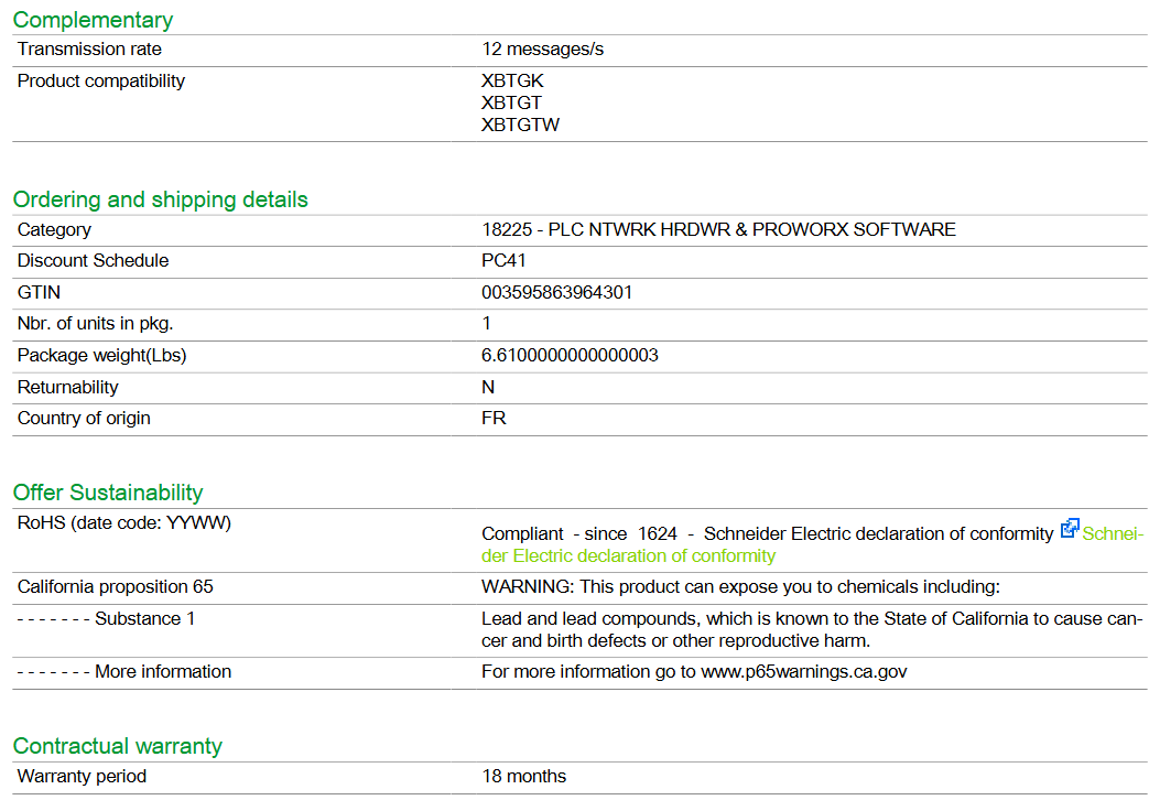
HART communication capability: As the host of HART field devices, it can receive 2 digital messages per second from the field devices, supporting HART universal commands, common commands, and device specific commands (which need to be implemented through Foxboro DCS Field Device Expert for HART tool), but does not support burst communication mode.

Power supply flexibility: Each channel is equipped with an independent isolated power supply, which can be powered internally or externally (when using an external power supply, a Cable Balun module is required to prevent crosstalk).

Basic compatibility: It needs to be compatible with I/A Series software v8.2-v8.8 or Control Core Services v9.0 or above, and connected to the Fieldbus Communication Module (FCM) or Control Processor (FCP) through a redundant 2Mbps fieldbus.

Key features and technological advantages

1. Core Features

Specific description of characteristic categories

Isolation protection is achieved between 8 channels, between channels and ground, and between channels and module logic circuits, with * * galvanic isolation (electrical isolation) * *. It can withstand 600VAC common mode voltage for 1 minute (without damage), avoiding signal interference and equipment damage.

High precision acquisition uses Sigma Delta (∑ – Δ) converters, with analog input values updated every 100 milliseconds for each channel to ensure data acquisition accuracy.

The environmental adaptability shell is made of extruded aluminum material, which is suitable for harsh environments and meets the * * Class G3 (harsh) environmental * * requirements of ISA standard S71.04. It supports industrial scenarios such as dust and humidity fluctuations.

Maintenance convenience supports “hot plugging”, which means that when replacing modules, there is no need to disconnect on-site wiring, power or communication cables; The front LED indicator light can visually display the module’s operating status and channel communication activity.

Redundant access to 2Mbps fieldbus (A/B dual path), automatically switches to another path in case of a single path failure, ensuring uninterrupted communication.

2. Special component: Cable Balun module

When multiple channels are powered by an external common power source, a Cable Balun module is required to maintain the balance of the HART communication line and prevent near end crosstalk (this module is not required for internal power supply channels). The core parameters are as follows:

Specific specifications of component information

Model CBM-4

Part number RH903SV

Each module contains 4 Balun units, with 1 unit corresponding to 1 external power supply circuit. The maximum increase in circuit resistance is 30 Ω

Installation requirements require the use of intrinsic safety barriers (such as MTL 787S+) to limit line energy in hazardous environments; External power supply can be connected in parallel with redundant power supply. It is recommended to cross connect the capacitor provided by the user to filter out AC power

Functional and Performance Specifications

1. Channel and communication parameters

Parameter category specific specifications

HART device compatibility supports HART ®  Devices with protocol v5, v6, v7 versions

External power supply for input resistor (including terminal components): 282 Ω; Internal power supply: 302 Ω

The internal power supply channel of the circuit power protection is designed with a current limit of less than 37mA to avoid overcurrent damage

Internal power supply output 24VDC ± 10%, output impedance 20 Ω (including terminal components)

Fieldbus communication redundancy 2Mbps fieldbus, bidirectional communication with FCM/FCP

2. Power supply and power consumption

Power parameter specifications

Input voltage (redundant) 24VDC, allowing+5%/-10% fluctuation

Maximum power consumption 8.4W

Maximum heat dissipation 5.6W

3. Calibration requirements

Modules and terminal components (TA) do not require regular calibration, and precision calibration has been completed at the factory, reducing maintenance workload.

Hardware and installation specifications

1. Core hardware components

Component type, model/part number, key parameters

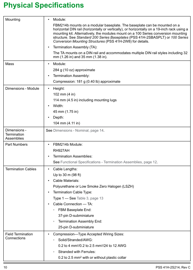
FBM214b module RH927AH weight: approximately 284g (10oz); Dimensions: Height 102mm x Width 114mm (including installation ears) x Depth 45mm (or Depth 104mm, depending on configuration)

Terminal Component (TA) RH924JH Material: Polyamide (PA, -20~70 ℃ temperature resistance); Wiring type: compression terminal; Weight: Approximately 181g (0.40lb)

Terminal cables are made of two materials (polyurethane/PVC, low smoke halogen-free LSZH), with a length of 0.5-30m (1.6-98ft), such as RH916DA (0.5m polyurethane) RH928AA(0.5m LSZH) 

Cable connection module side: 37 pin D-subminiature interface; TA side: 25 pin D-subminiature interface

2. Installation requirements

Specific requirements for installation category

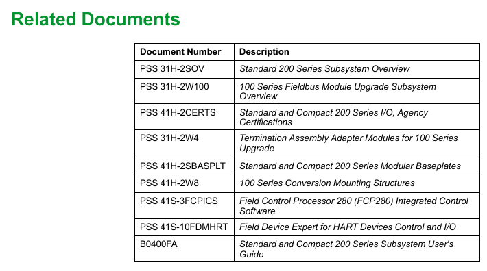
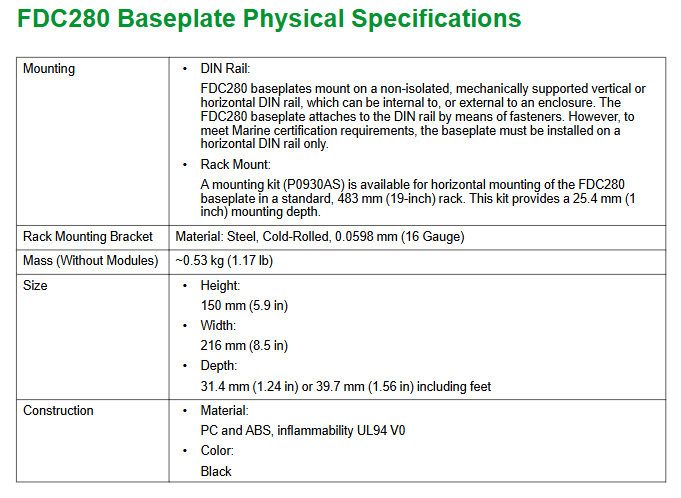
The module installation needs to be installed on a modular base plate, which supports horizontal/vertical DIN rail installation or can be adapted to a 19 inch rack through an installation kit; It can also be installed on the 100 series conversion installation structure (refer to PSS 41H-2W8)

TA is installed on 32mm or 35mm DIN rails and can be installed in the same cabinet or adjacent cabinets as the module (with a maximum cable length of 30m)

Wiring specifications support solid/multi strand wires (0.2~4mm ²/24~12AWG), multi strand wires with wire ears (0.2~2.5mm ², compatible with or without plastic sleeves)

Environmental and Compliance Specifications

1. Environmental parameters

Environment category, operating conditions, storage conditions

Temperature module/TA: -20~70 ℃ (-4~158 ℉) -40~70 ℃ (-40~158 ℉)

Relative humidity 5%~95% (no condensation) 5%~95% (no condensation)

Altitude -300~3000m (-1000~10000ft) -300~12000m (-1000~40000ft)

The anti pollution level complies with ISA S71.04 Class G3 and has passed the EIA 364-65 Class III exposure test-

Anti vibration 0.75g (5~500Hz)-

2. Compliance certification

Specific standards for certification categories

Electromagnetic compatibility (EMC) complies with EU directives 2004/108/EC (before April 20, 2016), 2014/30/EU (after April 20, 2016), and meets EN61326-1:2013 Class A (emission and industrial immunity)

Product Safety – UL/UL-C Certification in the United States/Canada: Suitable for cabinet systems with Class I A-D Group 2, T4 temperature code;

-EU Low Voltage Directive 2006/95/EC (before April 20, 2016), 2014/35/EU (after April 20, 2016);

-EU ATEX Directive 94/9/EC (before April 20, 2016), 2014/34/EU (after April 20, 2016): DEMKO certified Ex nA IIC T4 for Zone 2 hazardous environments

Environmental compliance complies with the EU RoHS Directive 2011/65/EU and revised versions 2015/863, 2017/2102

International Certification IECEx Certification

California Proposition 65 products contain lead and lead compounds, which may cause cancer or reproductive harm. For more information, please refer to www.P65Warning.ca.gov

Terminal Component (TA) and Cable Configuration

1. TA core parameters (RH924JH)

Specific specifications for TA

Adapt signal 8-channel 4-20mA analog signal/HART digital signal

Authentication Type 1+Type 2 Dual Authentication:

-Type 1: UL/UL-C Class I A-D Group 2 T4, ATEX Ex nA IIC T4 2;

-Type 2: UL/UL-C associated equipment (non flammable field circuit), ATEX IIC Zone 2 associated equipment, meets Class 2 current limiting requirements (below 60VDC/30VAC/100VA)

2. Terminal cable selection

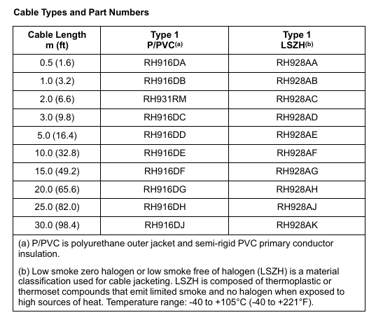
Cables are divided into two categories: “Polyurethane/PVC (Type 1 P/PVC)” and “Low Smoke Zero Halogen (Type 1 LSZH)”. The latter is suitable for scenarios that require smoke toxicity and corrosiveness (such as subways and data centers). The commonly used lengths and part numbers are as follows:

Length (m/ft) Type 1 P/PVC Part Number Type 1 LSZH Part Number

0.5/1.6 RH916DA RH928AA

1.0/3.2 RH916DB RH928AB

2.0/6.6 RH931RM RH928AC

3.0/9.8 RH916DC RH928AD

5.0/16.4 RH916DD RH928AE

10.0/32.8 RH916DE RH928AF

15.0/49.2 RH916DF RH928AG

20.0/65.6 RH916DG RH928AH

25.0/82.0 RH916DH RH928AJ

30.0/98.4 RH916DJ RH928AK

Foxboro ™  DCS Field Device Controller 280(FDC280)

Product Overview and Core Positioning

FDC280 is a distributed and optional fault-tolerant on-site installation controller, with the core function of implementing Foxboro ™  The integration of DCS and field devices does not require additional fieldbus modules (FBM), and it also undertakes process control and alarm tasks. It is mainly positioned as the “field device integration center”, which is different from the same type of FCP280 (which does not support PIO bus and focuses on Ethernet/serial protocol integration).

1. Core functions

Device integration: Directly interface with Ethernet/serial field devices that support multiple protocols, collect device data for display, historical storage, and execute control tasks.

Control capability: Built in adjustment control, logic control, timing control, sequence control functions, supporting alarm detection and notification.

Hardware architecture: Adopting dual core ARM ®  SOC processor with clear dual core division of labor:

Core 1 (Control Core): Run control software and DCS control network communication software, supporting fault-tolerant operations.

Core 2 (I/O core): Run device integration software, independently handle on-site device connections and status diagnostics.

Basic requirements: A host workstation with Foxboro DCS Control Core Services v9.3 or higher must be installed, and connected to the control network via 100Mbps fiber/copper Ethernet. It must have obtained ISASecure EDSA Level 1 security certification.

2. Key difference: FDC280 vs FCP280

Comparison item FDC280 FCP280

Core positioning on-site equipment integration (Ethernet/serial port) universal process control

PIO bus support not supported

Core advantage: No FBM required, directly integrated with field devices compatible with traditional PIO bus devices

Network configuration plan

FDC280 supports both Ethernet and serial network configurations, divided into two modes: “simplex” and “fault tolerant”, to meet the redundancy requirements of different field devices.

1. Ethernet network configuration

Support direct connection to Ethernet field devices or connection to serial devices through a “protocol specific gateway” (to achieve Ethernet serial bridging), with three core solutions:

Configuration Type Applicable Scenarios Key Features

Simplex, a single FDC280 module for scenarios with low reliability requirements, does not require redundant connections and saves wiring costs

Fault tolerant – Independent network with high reliability requirements, on-site equipment requires independent redundant network dual FDC280 modules (left/right), connected to two independent Ethernet networks provided by customers, with module IP addresses that can be the same or unique

Fault tolerant – Shared network field devices without independent redundancy requirements (such as single port devices). Dual FDC280 modules share one Ethernet network, supporting single port device access and reducing network complexity

Note: It is recommended to use a management switch for easy maintenance and troubleshooting; The device can also be directly connected to the FDC280 motherboard without the need for a switch.

2. Serial port network configuration

Each module of FDC280 contains 4 independently configurable serial ports (supporting RS232/RS422/RS485), with a maximum support of 128 serial field devices (up to 32 devices per RS485 port). The core solution is divided into 2 types:

Non fault-tolerant (Simplex): A single FDC280 can be connected to a single port serial device through a “Terminal Component (TA)”, supporting RS485 multi station connection without a modem and RS232/RS422 direct connection.

Fault tolerant type: Dual FDC280 modules are connected to devices through TA and adapted to different port devices:

Dual port device: The left/right module connects the two ports of the device separately to achieve redundant communication.

Single port device: RS232 needs to be connected to two TAs through a Y-shaped cable; RS485/422 can be directly connected through a dual module TA sharing connection.

Core features and performance parameters

1. Key functional characteristics

Specific description of characteristic categories

The device and I/O capacity support a maximum of 256 field devices, 8000 soft I/O points, and 8252 total functional blocks (including Station blocks, ECB components, etc.). Please refer to the FDC280 sizing tool (B0700GS) to calculate the load

The protocol supports 6 core protocols, some of which support concurrent multi instance/multi version (see table below for details)

The diagnostic capability has a built-in “diagnostic driver” that can capture real-time communication messages with the device and send them to the workstation diagnostic application without physical interruption

Fault tolerance mechanism dual module “marriage” operation, Control Network communication requires dual module messages to be matched bit by bit before sending; Core 1 supports primary/backup switching, while Core 2 supports redundancy state comparison and role handover

In self hosted mode, the control database checkpoint file is stored in flash memory, and the host can autonomously start and execute control policies when offline

Software updates distinguish between “Major updates (new features, no online upgrade support)” and “Minor updates (only module switching, no process interruption)”

Environmental adaptability die-casting aluminum shell, no need for ventilation, supports Class G3 harsh environment (ISA S71.04 standard), CE certification for on-site installation

Time synchronization supports GPS satellite UTC time (external) or DCS internal TimeKeeper synchronization (internal), with data timestamp accuracy of 10 times/second (minimum scanning interval of 100ms)

2. Support protocols and concurrency capabilities

Protocol name, part number, multiple protocols, concurrent support, same protocol, multiple instances support

Modbus TCP Client K0177AH Yes Yes

Modbus RTU&ASCII Client K0177CV Yes

Triconex ™  TSAA Client K0177DE is

OPC UA Client K0177EC (single instance only)

Is EtherNet/IP Scanner Driver K0177EP

PROFINET IO Controller K0177FU No No (single instance only)

3. Functional specification parameters

Specific numerical values for parameter categories

The maximum execution speed of functional blocks with a processor performance of 16000 blocks per second, and the minimum block processing cycle (BPC) of 100ms

The maximum capacity of a single sequence block is 32KB

IPC connects 200 data source points (providing external data), 30 sink points (receiving external data), and 1 dedicated internal point

OM (Object Manager) can scan a database with a maximum capacity of 28000 points (18000 points when BPC ≥ 200ms, 7500 points when BPC=100ms); The maximum convergence point is 11250 points

Configurable block period of 0.1/0.2/0.5/0.6/1/2/5/6/10/30 seconds, 1/10/60 minutes

Fault tolerant module pairing time is less than 0.5 seconds

Hardware and environmental specifications

1. Core hardware components and parameters

The FDC280 hardware includes four categories: “module”, “motherboard”, “network adapter”, and “terminal component”. The key parameters are as follows:

Component type, model/part number, key specifications

FDC280 module RH101FQ size: height 105/116mm (including installation ears) x width 51.8mm x depth 147mm; single module weight 0.8kg

The base plate RH101KF (2 bits) supports 1 non fault tolerant module or 2 fault tolerant modules, including 2 10/100Mbps/1Gbps copper cable Ethernet RJ45 interfaces, 2 37 pin D-type serial port interfaces, and 2 time synchronization interfaces

Network adapter fiber optic: RH924WA (Rev. E+); Copper cable: RH924UQ (Rev. D+) takes power from the base plate, fiber supports multimode 62.5/125 μ m cable (maximum 2km), copper cable supports Cat5 (maximum 100m)

Serial terminal component ring terminal post: P0926PA; Tightening screws: RH926GH weighs 363g and 272g respectively, and needs to be paired with Type 5 terminal cables (such as RH100HV-1m and RH100HZ-5m)

2. Power and environmental requirements

Category specifications

Power requirement input voltage: 24VDC (redundant,+5%/-10%); The maximum power consumption of a single module is 8.5W

Working temperature -20~60 ℃ (-4~140 ℉)

Storage temperature -40~70 ℃ (-40~158 ℉)

Relative humidity 5%~95% (no condensation)

Altitude operation: up to 3000m; storage: -300~12000m

Anti pollution level Class G3 (ISA S71.04), supports 10-year mixed gas exposure testing (EIA 364-65A Class III), module with conformal coating (conformal coating: protective coating)

Vibration resistance 0.5g (5~500Hz)

3. Compliance certification

Electromagnetic Compatibility (EMC): Compliant with Directive 2014/30/EU, EN 61326-1 Class A (Emission and Industrial Immunity).

Product safety: UL/UL-C certification (applicable to Class I, Groups A-D, Zone 2), EU Low Voltage Directive (2014/35/EU), ATEX Directive (2014/34/EU, DEMKO Ex nA IIC T4 Gc, applicable to Zone 2).

Environmental compliance: Compliant with the EU RoHS Directive (2011/65/EU and revised versions 2015/863, 2017/2102).

California Proposition 65: Products containing lead and lead compounds may cause cancer or reproductive harm, details can be found at www.P65Warning.ca.gov.

Fault tolerance mechanism and reliability design

The “fault-tolerant” core of FDC280 consists of dual module redundancy, independent diagnosis, and seamless switching, covering the control network, CPU, and I/O levels to ensure uninterrupted processes

1. Three layer fault-tolerant/redundant design

Level fault tolerance/redundancy mechanism switching logic

The dual modules of the control network are connected through the backplane and share control network access (dual switches). Communication messages need to be matched bit by bit by the dual modules before being sent. When a fault is detected, the non faulty module takes over control without process interruption

Core 1 (control core) primary/backup mode, real-time synchronization status. When the primary core fails, the backup core immediately switches to primary dynamic mode

Core 2 (I/O core) independently diagnoses the connection status of dual core devices. When the main core fails and the backup core device is better connected compared to the backup core status, the main core resets and hands over the role

The main module on the I/O side is responsible for reading and writing I/O points, while the backup module monitors device connections through “heartbeat commands” and synchronizes I/O values in real-time. When the main module loses connection, the backup module seamlessly takes over without any process fluctuations

2. Maintain convenience

Hot plug support: Replacing the FDC280 module does not require disconnecting the backplane power supply, and does not affect the field I/O signal of another module.

Status visualization: The front of the module includes an LCD display screen (displaying module identification, role, hardware version, network status) and LED indicator lights (running status, Ethernet connection status), supporting the configuration of “letterbug” through panel buttons.

Related documents and support

For further technical details, please refer to the following supporting documents:

Document Number Document Name Purpose

B0700GQ “FDC280 User Guide” Installation, Configuration, and Operation Guide

B0700GS “FDC280 sizing tool and Excel workbook guide” for calculating processor load and functional block capacity

PSS 41H-2SBASPLT “200 Series Standard Base Plate Specification” Base Plate Installation and Interface Instructions

PSS 41S-1TIME “Overview of DCS Time Synchronization” Time Synchronization Configuration and Accuracy Description

PSS 41S-3xxx protocol driver specifications (such as 41S-3FDCMBDV for Modbus TCP driver) specific protocol integration parameters

Schneider Electric Foxboro ™  DCS FPS480-24 Compact

Product positioning and core applications

Foxboro ™  DCS FPS480-24 is a 480W compact DC power supply launched by Schneider Electric, belonging to the Foxboro DCS system supporting equipment under the EcoStruxure architecture. Its core function is to provide stable 24V DC power supply for DCS system loads (such as FCP280 controller, Compact/Standard 200 series I/O subsystem equipment), and can also be expanded to power external field devices. Its design is compatible with K13 system enclosures and K14 system and terminal enclosures, supports customized configurations (meeting power consumption and wattage requirements), and has passed ATEX, UL, UL-C certifications. It can be used in Class 1, Division 2 (North America), and Zone 2 (International) hazardous areas, especially suitable for DCS system power supply needs in harsh industrial environments.

Core Features and Advantages

(1) Wide range input and high efficiency

Flexible input adaptation: automatically compatible with alternating current (AC) and direct current (DC) inputs, with an AC input range of 85-264V AC (47-63Hz, single-phase) and a DC input range of 120-264V DC (output reduced to 90% when 108-119V DC), meeting the voltage standards of power grids in different regions around the world without the need for additional transformers.

High efficiency and energy saving: With an efficiency of up to 94% (at 230V AC input), low energy consumption reduces operating costs. Based on average electricity prices and load calculations, the return on investment (ROI) can be less than 2 years; Built in power factor correction (PFC) circuit, with a power factor close to 1 when AC input (0.98 at 115V AC and 0.92 at 230V AC), reducing harmonic interference in the power grid.

(2) Security protection and reliability

Multiple protection mechanisms

Overcurrent protection: dual stage current limitation, automatically shuts down when the load current exceeds 105% of the rated value (at 25 ° C) for more than 4 seconds; The typical value of short-circuit current is 48A, and the output constant current setting value is about 32.5A to avoid short circuit damage to the equipment.

Overvoltage protection: When the output voltage is abnormally high, it will automatically shut down. The input power supply needs to be disconnected (within 30 seconds) to reset, and the power supply will be restored after troubleshooting.

Isolation and Insulation: The insulation resistance between input-output, output casing, and input-output casing is greater than 100M Ω (tested at 500V DC), and the insulation strength meets industrial safety standards to prevent leakage risks.

Environmental adaptability: The shell is coated with a conformal coating to prevent corrosion; The protection level and environmental tolerance meet the G3 level harsh environment standard, supporting working temperatures of -25~70 ° C (load linearly reduced to 75% at 60-70 ° C), relative humidity of 5-95% (no condensation), altitude of -300~3000m (storage altitude up to 12000m), no need for fans, and reducing mechanical failure points through natural convection heat dissipation.

(3) Compliance in hazardous areas

Complete certification: UL/UL-C certification (compliant with UL60950-1 and UL508 standards), ATEX certification (Ex nA IIC T3), IECEx certification, can be used in Class 1, Division 2 (Groups A-D), Zone 2 (IIC explosion group) hazardous areas, as an “associated device” to power non flammable communication circuits (requires coordination with designated processor modules, refer to the DIN Rail Installation Subsystem User Guide).

Technical specifications

(1) Input and output parameters

Category specification details

Input specifications – AC input: 85-264V AC (47-63Hz, single-phase), input current 4.5A at 115V AC, 2.3A at 230V AC

-DC input: 120-264V DC (108-119V DC with 90% derating), input current 4.5A

-Starting voltage: typical value 71.6V AC, shutdown voltage: typical value 66.7 V AC

Output specification – Output voltage: 24.0V DC (factory set ± 0.2V DC)

-Voltage regulation rate: Line regulation rate 96mV, load regulation rate 240mV

-Output current: rated 20A (480W), maintained at 20A at 60 ° C, reduced to 15A (360W) at 70 ° C

-Ripple and noise: typical value of 240mVpp, maximum value of 600mV (at -25~0 ° C)

-Temperature coefficient:<0.02%/° C

-Soft start time:<1 second (115V AC input)

-Holding time: 14ms (full power, 115/230V AC input)

(2) Physical and installation specifications

Installation method: Horizontal DIN rail installation (standard DIN rail bracket and fixture), detachable bracket supports panel installation.

Dimensions and Weight: The nominal dimensions are approximately 123mm (length) x 88mm (width) x 82mm (height), with a net weight of 1.3kg (2.87lb) and a gross weight of 1.45kg (3.2lb). The compact design saves cabinet space.

Connection method: M3 screw terminal connection, input and output cables need to be provided by the user. It is recommended to use 14AWG (high current circuit) or 18AWG (low current circuit) wires.

(3) Status monitoring and alarm

LED indication: Green “DC OK” LED indicates output voltage>19.2V (normal operation); The red “Peak” LED indicates that the output voltage is less than 80% of the rated value (under voltage or overload).

Relay alarm: The “DC OK” normally closed (NC) relay contacts close when the output voltage is greater than 80% of the rated value, and disconnect when it is less than 80% (such as short circuit, overload, or no input power). External alarm can be triggered by external modules such as FBM207b. The rated load of the relay contacts is 30V DC/1A, 110V DC/0.3A, 125V AC/0.5A, with insulation strength of 1000V AC (between contacts) and 1500V AC (between coils and contacts).

Environment and Compliance

(1) Environmental tolerance

Environmental indicators, operating range, storage range

Temperature -25~70 ° C (-13~158 ° F), linear load derating at 60-70 ° C -40~70 ° C (-40~158 ° F)

Relative humidity 5-95% (no condensation) 5-95% (no condensation)

Altitude -300~3000m (-1000~10000ft) -300~12000m (-1000~40000ft)

Vibration<19.6m/s ² (2G)-

(2) Electromagnetic Compatibility (EMC) and Safety Certification

EMC compliance: Compliant with IEC/EN 60950, UL60950-1, UL508, Semi F47 (only 200V AC) and other standards, with conducted emission (EN55022-B/CISPR22-B), radiated emission (EN55022-B/CISPR22-B), harmonic current (IEC61000-3-2 Class A) and other indicators meeting standards. Anti interference capabilities include: 8kV contact discharge/15kV air discharge (ESD), 2kV electrical fast transient (EFT), 2kV line to ground/4kV line to neutral lightning surge, 10V conducted RF common mode interference, etc.

Safety certification: UL file number E45026, CSA file number LR35579; ATEX certification (Ex nA IIC T3), CENELEC certification, meeting the requirements for use in hazardous areas; California Proposition 65 Warning: Products containing lead and lead compounds may cause cancer or reproductive harm. For more information, please refer to www.p65warnings. ca.gov.

Accessories and Connection Configuration

(1) Core accessory model

Accessory name, model, and purpose

The RH101CR core power supply unit of the power host provides 24V DC/20A output

AC input terminal block cable -1 cable is required to connect the terminal block to the power host

Connect the power supply to the Compact/Standard 200 series motherboard using RH100DY (3.7m), RH100DZ (0.6m), and RH100EA (1.0m) cables, with 14AWG supporting 20A current

DC distribution component RH101BY is used for multi board connection to achieve power distribution

Bottom board power cable (distribution component to bottom board) RH100EB (2.1m), RH100EC (3.0m) 18AWG, directly connecting the distribution component to the bottom board, supporting up to 2 bottom board direct connections

(2) Connection precautions

If only 1-2 base plates are connected, RH100EB/RH100EC cables can be directly used; If more than 2 baseboards are connected, power must be distributed through the RH101BY distribution component to avoid current overload.

It is recommended to use an independent power supply for external on-site equipment to avoid non system loads affecting the stability of DCS system power supply; All wiring must be fastened with M3 screw terminals to ensure reliable contact.

Key points for use and maintenance

Calibration requirements: The power supply is pre-set with a 24.0V DC output at the factory, which does not require user calibration or voltage adjustment, reducing maintenance workload.

Fault handling: After shutting down due to overvoltage/overcurrent, the input power supply should be disconnected first (within 30 seconds), and load faults (such as short circuits and overloads) should be checked before powering on again to restore power; When the “DC OK” relay is disconnected, it is necessary to check whether the output voltage is less than 80% of the rated value (19.2V DC), and troubleshoot input power supply, load, or internal power supply faults.

Installation spacing: To ensure natural convection heat dissipation, a ventilation gap of at least 76.2mm (3.0in) should be reserved around the power supply to avoid installation in close proximity to heating equipment.

GE Multilin 469 Motor Protection System

Product positioning and core values

The GE Multilin 469 motor protection system belongs to the SR relay family and is an integrated protection and management device designed specifically for medium and high voltage, large and medium-sized motors. It adopts a pull-out structure, balancing cost-effectiveness and industry-leading flexibility. Its core positioning is to provide comprehensive protection, precise control, simplified configuration, and advanced communication functions for medium and large three-phase motors (including high inertia, dual speed, and step-down starting motors), suitable for safe operation and management of motors and driving equipment in industrial scenarios. It can adapt to different motor characteristics through customized overload curves, single CT differential protection, and other functions. At the same time, with the help of motor parameter auto configurator, multi communication protocol compatibility, and other features, deployment and operation costs can be reduced, and equipment availability can be improved.

Core functions and protective features

(1) Comprehensive motor protection function

Hot model protection (core protection mechanism)

Multidimensional thermal management: integrating six core elements: overload curve (standard/customized/voltage dependent), negative sequence current bias (compensating for additional rotor heating), cold and hot safety stagnation ratio (defining the steady-state thermal capacity utilization rate of the motor), cooling time constant (distinguishing the heat dissipation rate during operation/shutdown), startup suppression and emergency restart (preventing startup when the thermal capacity is insufficient), RTD bias (combined with stator RTD temperature correction thermal model), updating the thermal capacity utilization rate (TCU) every 0.1 seconds, accurately simulating the actual thermal state of the motor.

Overload Curve Characteristics: Provides 15 standard overload curves (multiplier 1-15). The voltage dependent curve is suitable for high inertia loads and can dynamically adjust the thermal overload curve during the acceleration phase according to the system voltage, avoiding motor overheating caused by acceleration time exceeding the safe dead time.

Fault and abnormal working condition protection

Electrical fault protection: covering stator differential protection (supporting 6 CT external summation or 3 flux balanced CT connection, distinguishing the tripping threshold for startup/operation status), short circuit protection (removing the DC component of fault current, supporting secondary tripping backup when the fault is not cleared), grounding fault protection (supporting zero sequence CT, high sensitivity CT, phase CT residual connection, dual tripping/alarm threshold).

Abnormal working condition protection: including mechanical jamming (detecting rotor stalling, locking during startup), acceleration time monitoring (preventing abnormal long acceleration process), undervoltage/overvoltage (independent threshold during motor startup/operation phase, supporting locking in case of VT fuse failure), underfrequency (adjustable from 20-60Hz), over torque (adjustable from 1.0-999999.9 Nm/ft lb, only induction motor alarm), current imbalance (detecting negative sequence current ratio, including phase failure detection algorithm, dual trip/alarm threshold), etc.

Temperature and hardware protection

RTD Temperature Monitoring: Supports 12 programmable RTD inputs (compatible with Platinum 100, Nickel 100/120, Copper 10, etc.) to monitor stator, bearing, and ambient temperature. Each RTD includes three levels of thresholds: alarm, high alarm, and trip. Supports RTD trip voting and open/short circuit fault alarm.

Other hardware protections: including reverse power (to prevent motor from generating electricity due to reverse dragging), underpower (to detect load loss), abnormal power factor (synchronous motor out of step detection), limit on starting times/starting intervals (to prevent excessive starting losses), etc.

(2) Control and configuration functions

Flexible control mode: supports dual speed motor protection (independent overload curve), voltage reduction start monitoring (transition current/time control), frequency conversion filtering (suitable for accurate acquisition of analog signals in VFD scenarios), analog input differential calculation (dual drive system application), trip coil monitoring, etc., to meet the control requirements of different starting modes and operating scenarios.

Simplified configuration tool: equipped with a motor parameter auto configurator, complete parameter settings through a 6-step guided operation; Support on-site firmware and parameter upgrades, with optional conformal coatings for chemical corrosion/humid environments to enhance equipment adaptability.

Monitoring, measurement, and diagnostic capabilities

(1) High precision measurement function

Electrical parameter measurement: Real time monitoring of phase current, differential current, grounding current, average current, current imbalance, phase voltage/line voltage, average voltage, frequency, as well as active/reactive/apparent power, power factor, electrical energy (Wh/var), torque, demand value, etc., with measurement accuracy of ± 0.5% (when current<2 times CT) and ± 1% (when current>2 times CT).

Non electrical parameter measurement: 12 channel RTD temperature (range -50~250 ℃, accuracy ± 2 ℃), motor speed (100-7200 RPM, supporting inductive/Hall sensors), analog input (4-20mA/0-20mA/0-1mA, accuracy ± 1% of full range).

(2) Data recording and diagnosis

Event Recorder: Timestamp records system events, storing up to 256 events for easy tracing of fault causes.

Waveform capture: Record 10 waveforms (Ia/Ib/Ic/IG/Diffa/Diffb/Diffc/Va/Vb/Vc) during tripping, with 12 samples per cycle and a total of 64 cycles of data, supporting fault waveform analysis.

Advanced diagnosis: optional rotor bar breakage detection function, continuously monitoring the health status of the rotor through motor current signal analysis (MCSA), early warning of rotor faults (such as starting torque drop, overload, bearing wear), supporting programmable alarms, and achieving predictive maintenance.

Simulation testing: Pre trip and fault conditions (current, voltage, frequency, RTD temperature, etc.) can be simulated without external input, simplifying the debugging and commissioning process.

Hardware specifications and interface configuration

(1) Input/output interface

Current and voltage input

Current input: 2 sets of three-phase CT inputs (phase current CT supports 1A/5A secondary side, specified when ordering; Differential CT field programmable 1A/5A), 2-channel grounded CT input (standard CT supports 1A/5A, high-sensitivity CT supports 50:0.025A), CT withstand capability up to 80 times rated current for 1 second, 40 times rated current for 2 seconds, and 3 times rated current for continuous operation.

Voltage input: Three phase VT input (supporting star/delta connections, full range 273V AC, accuracy ± 0.5% full range, frequency range 20-120Hz), supporting VT fuse fault detection.

Digital and Analog Interface

Digital input: 9-way optically isolated input (5 pre-defined: starter status, emergency restart, remote reset, parameter access, test switch; 4 assignable: remote trip/alarm, speed switch, vibration switch, pressure switch, etc.), supports dry contact or NPN collector input.

Analog input/output: 4-channel configurable analog input (supports 4-20mA/0-20mA/0-1mA, input impedance 226 Ω± 10%), 4-channel configurable analog output (specify 4-20mA or 0-1mA when ordering, accuracy ± 1% of full scale, 4-20mA maximum load 1200 Ω, 0-1mA maximum load 10k Ω).

Output relays: 6 sets of Form-C output relays (4 sets of non fault safe type, can be assigned with trip/alarm function; 1 set of non fault safe type start interlock relay; 1 set of fault safe type service relay, indicating loss of control power or internal fault), supporting interlock function, with a maximum rated contact value of 10A continuous (DC 30V 300W, AC 250V 2770VA).

(2) Human Computer Interaction and Communication

Local interaction: 40 character display screen (displaying parameters, actual values, fault/alarm information), numeric keypad (parameter input and navigation), 22 LED indicator lights (system status, motor status, output relay status), supporting 20 user-defined default messages.

Communication capability: Comes standard with 3 serial ports (front RS232 for debugging, rear 2 RS485 for remote communication), optional 10BaseT Ethernet and DeviceNet ports; Supports Modbus RTU (serial port) and Modbus TCP/IP (Ethernet port), multiple ports can communicate simultaneously, and Ethernet can be connected to local/wide area networks, replacing multi drop wired networks and reducing operation and maintenance costs.

Software and Operations Support

(1) EnerVista software suite

Configuration and Debugging Tools: Provides automatic configuration of motor parameters, firmware upgrades, parameter backup/recovery functions, supports waveform and event viewing, and simplifies fault diagnosis.

Monitoring and integration tools: Viewpoint Monitoring provides plug and play device monitoring, single line diagram monitoring and control, alarm annunitor, trend reports; EnerVista integrator includes OPC/DDE servers, Multilin drivers, and supports seamless integration with existing HMI/SCADA systems.

Maintenance tool: Viewpoint Maintenance provides parameter audit tracking reports, equipment health reports, and comprehensive fault diagnosis to enhance operational security and efficiency.

(2) Pull out structure and retrofit support

Pull out design: easy to replace quickly, reduces downtime, supports wire lead sealing to prevent unauthorized removal.

Retrofit upgrade: With the 8 series Retrofit kit, old SR 469 relays can be upgraded to 869 motor protection systems without modifying existing panel openings, rewiring, or changing drawings. The upgrade process only requires 3 steps (updating parameter files, removing old relays, plug-in reconnection) and can be completed in as fast as 21 minutes, reducing upgrade costs and system downtime.

Technical specifications and environmental adaptability

(1) Key technical parameters

Category specification details

Current measurement CT primary side 1-5000A, secondary side 1A/5A; Accuracy: ± 0.5% for current<2 times CT, ± 1% for current>2 times CT

Voltage measurement VT ratio 1.00-15.00:1, secondary side full range 273V AC; Accuracy ± 0.5% of full scale

RTD measurement supports 4 types of RTD, with a range of -50~250 ℃ and an accuracy of ± 2 ℃. Each channel has a 3-level threshold (alarm/high alarm/trip)

Communication speed serial port baud rate 300-19200 bps, Ethernet 10Mbps

Low range of power supply: DC 24-60V/AC 20-48V; High range: DC 90-300V/AC 70-265V, power 45VA (maximum)

(2) Environment and Compliance

Environmental adaptability: working temperature -40~+60 ℃, storage/transportation temperature -40~+80 ℃, humidity 0-95% (55 ℃ without condensation), protection level IP40 (front)/IP20 (back), pollution level 2.

Compliance certification: Compliant with EN60255 series, IEC 61000 series, UL508/UL1053, cULus and other standards, passed ISO9001 quality system certification, CE certification (EN60255-5/27, EN61010-1, etc.).

Ordering and configuration options

(1) Basic models and core options

Basic unit: The model starts with “469”, and subsequent codes distinguish key configurations:

CT secondary side: P1 (1A), P5 (5A);

Control power supply: LO (low range: DC24-60V/AC20-48V), HI (high range: DC90-300V/AC70-265V);

Analog output: A1 (0-1mA), A20 (4-20mA);

Extended functions: D (DeviceNet), E (Enhanced Front Panel), T (Enhanced Front Panel+Ethernet), H (Anti harsh Environment Coating).

(2) Optional accessories

Including pull-out handle (with lead seal), RTD sensor, CT/VT of different specifications, Retrofit upgrade kit (including terminal block and depth reduction ring compatible with old SR relays), EnerVista software kit, etc., can be flexibly selected according to on-site needs.

image.png

Honeywell System 57 5704 Control System

Product positioning and core functions

The Honeywell System 57 5704 control system is a microprocessor controlled device used for industrial gas detection, belonging to the System 57 product family. Its core function is to monitor industrial gas detectors installed on site, achieve multi-channel gas concentration monitoring, alarm triggering, and system management. It is suitable for indoor non hazardous areas and should not be exposed to rainwater or moisture. It is also not designed for use in hazardous areas. The system supports catalytic and 4-20mA input types of gas sensors, with flexible alarm configuration, remote control, and self diagnostic capabilities. Calibration, maintenance, and parameter settings can be performed through engineering cards, and it is also compatible with extended functions such as Modbus communication and event printing.

System composition and hardware specifications

(1) Core hardware module

Four Channel Control Card

Type differentiation: divided into catalytic input type (model 05704-A-0144) and 4-20mA input type (model 05704-A-0145). The former supports catalytic gas sensors and provides constant current drive (adjustable from 90-315mA), while the latter is suitable for 4-20mA circuit power supply sensors with a measurement range of 0-25mA.

Display and indication: Equipped with four LCD displays (25 segment analog bar, 4-digit digital display, 4-digit message display, icon area), 4 channel LEDs (CHL1-CHL4) and 1 Attention (ATTN) LED, which can distinguish A1/A2/A3 alarm, STEL/LTEL alarm, fault, suppression and other states by LED flashing frequency/color.

Core parameters: Initial accuracy ± 1%, alarm set point resolution 1% of full range, electronic drift<± 3%/6 months, operating voltage 18-32V DC, catalytic type maximum power consumption 12.8W, 4-20mA type maximum power consumption 8.3W.

relay interface module

Quad Relay Interface Card (model 05704-A-0121): Provides 4 Single Pole Double Throw (SPCO) relays, supporting latch/non latch, power on/off action modes, and rated relay contacts 5A@110 /250V AC or 32V DC, supporting interface connection between sensors and control cards, with a maximum power consumption of 1.7W.

Relay Interface Assembly (model 05704-A-0131): It consists of four relay interface cards and an extended relay card, including 12 SPCO relays and 4 Single Pole Single Throw (SPST) relays, occupying 2 card slots, with a maximum power consumption of 6.5W, suitable for scenarios that require more relay outputs.

Engineering Card (Model 05701-A-0361)

Functional positioning: The core module for system configuration, calibration, and maintenance, equipped with green power LED, red unlock LED, as well as directional keys (up/down), confirm/cancel keys, function keys (BEAD mA, ALARMS, ZERO, SPAN, etc.).

Core Capability: Supports sensor bridge current regulation, alarm threshold setting and relay testing, zero/range calibration, system clock setting, can be configured and data printed through RS232 interface connected to printer or PC, with a power consumption of approximately 1.5W.

DC Input Card (Model 05701-A-0325)

Function: Provides a system DC power supply interface, supports two independent power inputs (such as main power and backup battery), has diode isolation and 10A anti surge fuse, supports 2.5mm ² (14 AWG) wire terminals, and operates at a voltage of 18-32V DC.

other modules

Analog output module: divided into current absorption type (04200-A-0145) and current source type (04200-A-0146), output range 0-20mA or 4-20mA software optional, linearity ± 2% of full range, supporting external power supply of 18-40V.

Expansion module: including event printing module (05701-A-0314), Modbus interface module (RS232 type 05701-A-0313, RS485/422 type 05701-A-0312), alarm update module (05701-A-0309), etc., used to expand communication and alarm functions.

(2) System rack and cabinet

Rack: available in full 19 inch and half 19 inch widths, supporting front or rear wiring, including engineering cards, DC input cards, and interconnecting cables (front wiring type), made of galvanized steel, with M5 grounding terminal bolts, weighing approximately 287.6-217.6g including modules (depending on model).

Cabinet: divided into 8 channels (model 05701-A-0452) and 16 channels (model 05701-A-0451), made of low carbon steel, RAL 7015 dark gray, equipped with knockout cable sealing sleeves (8 channels include 2 M25, 8 M20, etc.), weighing 10kg for 8 channels and 13.5kg for 16 channels.

(3) Power supply unit

AC-DC power supply unit: divided into 8 channels (model 05701-A-0406) and 16 channels (model 05701-A-0405), input 85-264V AC (47-440Hz) or 110-340V DC, output 24V DC ± 10%, can be upgraded by adding a 50W switch module (model 05701-A-0440) (maximum 100W for 8 channels, maximum 200W for 16 channels), with overload protection (triggered by 105% rated load, automatic recovery), maximum leakage current 0.75mA/50W module.

Installation and wiring requirements

(1) Environment and Location

For indoor use only, avoid heat sources, moisture, and physical damage. The ambient temperature is -5-55 ℃ (ATEX certification system is 0-55 ℃), the humidity is 0-90% RH (no condensation), and the altitude is ≤ 2000m.

The installation of sensors should follow the characteristics of gas density (installation height for gas sensors lighter than air, installation height for sensors heavier than air), avoid areas where airflow is obstructed, quiet corners, and near heat sources, and be easy to maintain.

(2) Wiring and Connection

Sensor wiring: It is necessary to use cables with grounding and external shielding to avoid parallel interference sources such as AC power lines and motors. The maximum length of the cable depends on the type of sensor and the cross-sectional area of the wire (for example, when using 2.5mm ² wire for catalytic sensors, the maximum length is 2500m, and when using 2.5mm ² wire for 4-20mA sensors, the maximum length is 16000m). The shielding layer is only grounded at the cabinet end.

Power and relay wiring: The rated current of the power cable should be greater than the maximum load. If the relay cable is connected to an AC power source, a 5A fuse is required. The DC input card and relay interface card terminals support 2.5mm ² wires. When wiring, the power should be disconnected to avoid short circuits.

(3) Power configuration

The total power consumption of the system needs to be calculated through the “power budget table”, depending on the sensor type, number of channels, and module configuration; When there are more than 8 catalytic control cards, it is recommended to supply power separately through the four relay interface card to avoid the backplane current exceeding the 8A limit.

Supports dual input of main power supply and backup battery, with diode isolation achieved through a DC input card. The backup battery needs to be compatible with 18-32V DC specifications.

Operation and maintenance process

(1) Basic operation (without engineering key)

Control card reset and selection: Short press the RESET/SET button to reset inactive alarms and clear peak display; Long press and hold for 1.5 seconds to select the control card, then use the up and down keys on the engineering card to select the channel; Press and hold for 5 seconds to perform an extended reset (clear maximum/minimum readings, reset STEL/LTEL timer).

Basic functions of the engineering card: It can view the catalytic sensor bridge current (BEAD mA key), alarm threshold (ALARMS key), sensor signal (SIGNAL key), and system clock (CLOCK key). Calibration, suppression, and other operations cannot be performed without a key, and the selection will be automatically canceled after 30 seconds of timeout.

(2) Engineering operation (requires inserting the engineering key to unlock)

Channel suppression (INHIBIT key): After selecting a channel, press the INHIBIT key to switch the suppression state. During suppression, the channel LED will remain amber and the relay will be locked in an inactive state to avoid false alarms during calibration or troubleshooting.

Calibration process

Zero calibration (ZERO key): Ensure that the sensor is in a gas free environment, press the ZERO key, wait for the signal to stabilize (message displays “STANBLE”), and then press the confirm key. The system will automatically set the current signal to zero. If the signal exceeds the range, an error will be displayed.

Range calibration (SPAN key): Suitable for calibrated sensors, press the SPAN key to set the target range concentration, introduce the corresponding concentration standard gas, confirm after the signal is stable, and the system updates the range parameters; The new sensor requires the “1st SPAN” key to perform the first range calibration and record the initial sensitivity for lifespan monitoring.

Alarm and Relay Testing: Press the ALARMS key to set the A1/A2/A3/SETL/LTEL threshold. After switching to “TEST” mode, simulate gas concentration changes by pressing the up and down keys to verify whether the alarm LED and relay actions are normal. During testing, be sure to release the suppression to trigger the external relay.

(3) Maintenance and troubleshooting

Regular maintenance: It is recommended to check the terminal fastening, LED status, sensor signal and alarm function every year. The catalytic sensor needs to be calibrated regularly (according to the sensor manual). When the sensitivity of the catalytic sensor drops below 50% of the initial value, the system displays “Lifetime Expired” and the sensor needs to be replaced.

Fault diagnosis: Identify the problem through the error codes displayed on the control card message (such as ER97 for EEPROM fault, ER87 for over range fault, ER83 for bridge current fault), and check the power supply, wiring, and sensor status using the “troubleshooting table”. Hardware faults require replacement of the corresponding module.

Data recording: It can be connected to an RS232 printer through an engineering card, and long press the up and down keys to print single channel status or overall rack summary data, including sensor type, calibration date, alarm threshold, relay configuration, and other information.

Compliance and safety requirements

(1) Certification and Standards

Compliant with EN50054/57/58 (General Requirements and Performance for Combustible Gas Detection), EN50271 (Software and Digital Technology), EMC Directive 89/336/EEC (EN50270:1999), Low Voltage Directive 73/23/EEC (EN 61010-1), ATEX certification based on EC Type Examination Certificate BVS 04 ATEX G 001 X, suitable for Zone 2 hazardous areas (requiring tested enclosures).

(2) Safety operation standards

Installation and maintenance should be carried out by professionals, and wiring should be operated after power failure to avoid equipment damage caused by incorrect sensor wiring; When used in hazardous areas, it is necessary to comply with the installation standard EN 60079-14 to ensure the enclosure protection level and explosion-proof requirements; The data read by Modbus is only used for visualization or recording and cannot be used for safety related control to avoid Modbus write operations.

Ordering and Accessories

Core module ordering models: Control card, relay interface card, engineering card, DC input card, etc. The core module models are clear, and the power unit, cabinet, and rack need to be selected according to the number of channels and installation requirements (such as 8-channel cabinet 05701-A-0452, 16 channel power supply 05701-A-0405).

Optional attachments: including blank panel (05701-A-0365), engineering key kit (05701-A-0550), interconnect cable (05704-C-0160), liquid tight connector kit, etc. Expansion modules such as Modbus interface and event printing module need to be ordered separately.

Sakae toshin FCPS22AC, FCP22A, FCP30A series potentiometers

Overall positioning and common features of the product

The FCPS22AC, FCP22A, and FCP30A series launched by Sakae toshin are all single turn conductive plastic servo installed potentiometers, which are core compatible with precision and stability requirements for speed and voltage regulation in industrial control, automation equipment, and other scenarios. They all comply with RoHS environmental standards and have common advantages such as “oil-free metal bearings (some models)”, “infinite resolution”, and “low contact resistance variation”. The mechanical stroke is 360 ° unrestricted rotation, suitable for continuous adjustment scenarios.

Comparison of core parameters of various models

(1) Differences in basic specifications and dimensions

Model size characteristics (key dimensions, unit: mm) Weight Bearing type Power rating

FCPS22AC overall dimensions: 20 (length) x 11.5 (width) x 8.2 (height), mounting hole: 2 x M2 (depth 5), shaft related dimensions: 1.57 ± 0.2 (two locations), maximum 0.8 (shaft diameter related), approximately 20g oil-free metal bearing 1.0W

FCP22A overall dimensions: 15 (length) × 11.5 (width) × 12 ± 0.2 (height), mounting hole: 2 × M2 (depth 4), outer diameter: φ 22.23 (+0.13/-0.25), φ 19.05/φ 19.1, arc radius R18MAX about 15g unspecified (default servo installation adaptation structure) 1.0W

FCP30A overall dimensions: 15 (length) × 11.5 (width) × 15 ± 0.2 (height), mounting hole: M3 (depth 4), outer diameter: φ 26.97 (+0.13/-0.25), φ 27 ± 1/φ 24, arc radius R20MAX about 25g not clearly marked (default servo installation adaptation structure) 1.5W

(2) Differences in electrical performance

Performance indicators FCPS22AC FCP22A FCP30A

Standard resistance values 1k, 2k, 5k, 10k Ω 1k, 2k, 5k, 10k Ω 1k, 2k, 5k, 10k Ω

Special resistance values 500, 20k, 50k, 100k Ω 500, 20k, 50k, 100k Ω 500, 20k, 50k, 100k Ω

Total resistance tolerance standard level ± 15% (L), precision level ± 10% (K) standard level ± 10% (K) standard level ± 10% (K)

Independent linear tolerance standard grade ± 1.0%, precision grade ± 0.5% standard grade ± 1.0%, precision grade ± 0.5%, ultra precision grade ± 0.25% standard grade ± 1.0%, precision grade ± 0.5%, ultra precision grade ± 0.2%

Electrical stroke 320 °± 5 ° 320 °± 5 ° 340 °± 5 ° (longest stroke, wider adjustment range)

Insulation resistance>1000M Ω at 500V DC>1000M Ω at 1000V DC (stronger insulation performance)>1000M Ω at 1000V DC (stronger insulation performance)

Dielectric strength: withstand for 1 minute at 500V AC, withstand for 1 minute at 1000V AC (stronger resistance to voltage breakdown), withstand for 1 minute at 1000V AC (stronger resistance to voltage breakdown)

Starting torque ≤ 5mN · m (50gf · cm) ≤ 1.5mN · m (15gf · cm) (minimum torque, smoother adjustment) ≤ 2mN · m (20Gf · cm)

Temperature coefficient of resistance ± 400p.p.m./℃± 400p.p.m./℃± 400p.p.m./℃

Common Special Specification Options (applicable to the entire series)

Each model supports customized specifications to meet specific scenario requirements, mainly including:

Extra tap: Supports up to 1 tap, suitable for multi gear fixed voltage/resistance output requirements.

Axis extension design: Front and rear axis extension (default diameter of 3mm for rear axle, 10mm for FCPS22A/FCP30A, 20mm for FCPS22AC), suitable for connection requirements in special installation spaces.

Limiting device: After installation, the rotation angle is limited to 320 °, and the limiting strength is 0.9N · m (9kgf · cm) for FCPS22AC and 0.3N · m (3kgf · cm) for FCP22A/FCP30A, to prevent equipment damage caused by excessive rotation.

Special electrical stroke: Non standard electrical stroke can be customized according to requirements (default 320 °± 5 ° or 340 °± 5 °).

Shaft diameter and processing: Supports special shaft diameters (such as British size of φ 3.175mm, φ 6.35mm) and special processing of shaft bodies (such as slotting, rolling, etc.).

Multi link structure: FCP22A/FCP30A supports up to 5 link structures, with an increase in shell length of 8.5mm for each additional link, suitable for multi-channel synchronous adjustment scenarios.

Precautions

Customized specification impact: If special specifications are selected (such as multi link, special shaft, customized stroke), the general specifications of the potentiometer (such as insulation resistance, torque) and environmental adaptability may change, and it is necessary to communicate and confirm with the manufacturer in advance.

Installation and use: The appropriate screws should be selected according to the installation hole size of each model (such as 2 × M2 for FCPS22AC and M3 for FCP30A) to avoid over tightening and damaging the housing; When making electrical connections, it is necessary to match the power rating (such as FCP30A maximum 1.5W) to prevent overload and burnout.

Environmental adaptation: The waterproof and dustproof levels are not clearly marked, and it is assumed to be suitable for dry, non corrosive indoor industrial environments. Additional protection is required for harsh environments.

ABB LD 810HSE Ex Foundation fieldbus connection equipment

Core positioning and basic attributes of the product

(1) Product identity and functional positioning

ABB LD 810HSE Ex is a foundation fieldbus ™  Fieldbus connects devices and is registered as a 42c class device according to the HSE protocol specification. Its core function is to serve as a gateway between the FF high-speed Ethernet (FF-HSE) subnet and the FF-H1 link, enabling data exchange and device management between different bus types. It also supports device redundancy and ensures communication stability in industrial control scenarios.

(2) Physical and installation characteristics

Protection level: IP20, only suitable for indoor environments, must avoid direct sunlight, and has no impact protection or IP54 protection capability. When installed in hazardous areas, it must be equipped with a protective shell that meets the requirements of IEC/EN 60079-0 Section 26.4 (with impact resistance and corresponding IP level).

Installation method: DIN rail installation, suitable for standardized installation scenarios inside industrial control cabinets.

Power supply requirements: 24V DC power supply is required (power supply range 18V DC -32V DC, and must be SELV/PELV power supply), with a typical input current of 200mA, 4 FF-H1 channels each with an output current of 10mA, and a maximum current of 1A (including startup surge current).

Core functions and communication capabilities

(1) Gateway core functions

H1 Link Management: Supports up to 4 independent FF-H1 links, and devices in each link can act as Link Masters and SM Time Publishers, responsible for identifying devices connected to the H1 link, configuring system and network management for H1 devices through HSE, and accessing the functional blocks of H1 devices.

Data forwarding and alarm distribution: Implement process data forwarding between H1 links, bidirectional process data forwarding between H1 and HSE subnets, and distribution of alarms and events sent by H1 devices to ensure efficient flow of industrial process data between different bus levels.

HSE side management function: integrates System Management Agent, Network Management Agent, and FMS server (providing H1 device object access capability), supports Simple Network Time Protocol (SNTP) servers based on HSE specifications (for SM time synchronization), but does not support Simple Network Management Protocol (SNMP); Maintenance functions can be implemented through a web server, including firmware updates for connecting devices and H1 power modules (supporting http/https protocol).

(2) Communication performance and limitations

1. Maximum limit on HSE side

Indicator values

64 HSE sessions have been configured

400 HSE virtual communication relationships (VCRs) have been configured

Automatic HSE session count 32

128 automatic HSE virtual communication relationships (VCRs)

H1-H1 data forwarding count 64

2. Maximum limit for a single H1 channel

Explanation of Indicator Values

The total number of VCRs (VCRs) for source/sink, client/server, and publisher/subscriber types in a single H1 channel must not exceed 128

Number of overnight connections (alarm reception) 10-

Number of clients+servers 39+1-

100 publishers and subscribers-

LAS scheduling table number 2-

Number of sub scheduling tables 4-

The number of sequences in each sub schedule table is 64-

The number of elements in each sequence is 4-

LAS scheduling table field size 2000 bytes-

3. Other communication characteristics

H1 Link: Supports H1 Live List, which records device node addresses, PD tags, and device IDs; supports access to H1 port MIB (Management Information Base), but restricts write permissions on the H1 network side; The FF-H1 physical layer complies with Class 114 specifications, with a fieldbus voltage range of 9V DC to 32V DC (recommended 24V DC).

Ethernet: Compatible with IEEE 802.3 standard, supporting speeds of 10Mbit/s or 100Mbit/s, meeting the communication needs of industrial Ethernet.

Applicability and Compliance of Hazardous Areas

(1) Dangerous Area Certification and Applicable Scenarios

1. North American Certification (cULus)

If the device label indicates relevant information, it can be used for Class 1, Division 2, A/B/C/D hazardous areas, or non hazardous areas.

2. European and international certifications (ATEX, IECEx)

Applicable standards: evaluated according to IEC 60079-0:2011 (revised 6, including 2012/2013 revisions), IEC 60079-11:2011 (revised 6, including 2012 revisions), IEC 60079-15:2010 (revised 4), and corresponding EN standards.

Applicable to hazardous areas: If the equipment label or technical documentation indicates relevant information, it can be used in Zone 2 gas explosion environments with IIA/IIB/IIC explosion groups and T4 temperature levels when paired with tested enclosures.

Explosion proof marking: IECEx marking is “Ex nA [ic] IIC T4 Gc”, ATEX marking is “II3G nA [ic] IIC T4 Gc”, where the “[ic]” explosion-proof method is only applicable to the FF-H1 fieldbus interface; Comply with the requirements of Directive 2014/34/EU and strictly follow the hazardous area system installation standards such as IEC/EN 60079-14 during installation.

(2) Other Compliance

Safety standards: Compliant with IEC/EN/UL 61010-1 (Safety Requirements for Electrical Equipment for Measurement, Control, and Laboratory Use – Part 1: General Requirements) and IEC/EN/UL 61010-2-201 (Part 2-201: Special Requirements for Control Systems), and certified by the CB system.

Coating standard: The conformal coating complies with ANSI/ISA-S71.04 G3 standard, enhancing the equipment’s ability to resist environmental interference.

System integration and environmental adaptability

(1) ABB Ability ™  IT system integration

Typical integration architecture: In the ABB 800xA system, the Foundation fieldbus subsystem is connected to the control system through the HSE subnet, and LD 810HSE Ex serves as the gateway between the H1 link field equipment and the HSE subnet; The AC 800M controller interacts with the HSE subnet through the communication interface module CI860 (as the HSE host), and the engineering workstation (Control Builder M), operation and maintenance workstation, etc. access fieldbus data through FF connection servers (with OPC servers).

Redundancy integration: Supports LD 810HSE Ex device redundancy, where the corresponding H1 ports of redundant devices are connected to the same H1 link, and redundant control information is exchanged through redundant link wiring to enhance system reliability; The periodic process data on the H1 link can be forwarded to the HSE subnet through HSE, enabling periodic communication between different H1 link devices and HSE subnet devices. At the same time, H1 device alarms and events can be uploaded to the FF connection server and integrated into the 800xA system alarm management system.

(2) Environmental adaptation parameters

Scope of environmental indicators

Working temperature -40 ° C -+70 ° C

Storage temperature -40 ° C -+85 ° C

Relative humidity 10% -95% (non condensing)

Altitude not exceeding 2000m

Schneider TSXCUSBFIP USB gateway (Fipway/Fipio bus)

Product Core Information

(1) Basic positioning

Product series: Magelis XBT series, belongs to communication accessories, specifically USB gateway, mainly used for terminal devices, supports Fipio and Fipway bus types, can realize communication connection between USB interface of related devices and Fipway/Fipio bus.

Inventory status: Non Stock, usually not regularly stocked in distribution facilities. When purchasing, attention should be paid to the supply cycle.

(2) Key performance parameters

Transmission rate: 12 messages/second (12 messages/s), which specifies the efficiency of data transmission between the bus and USB interface, suitable for industrial control scenarios with moderate communication speed requirements.

Product compatibility: It is compatible with XBTGK, XBTGT, and XBTGTW terminal devices under the Magelis XBT series, ensuring stable communication functionality in specific device combinations. When selecting, it is necessary to match the corresponding compatible models.

Ordering and Logistics Details

Category specific information

Product Classification Code 18225- PLC Network Hardware and PROWORX Software (18225- PLC NTWRK HRDWR&PROWORX SOFT)

Discount Plan PC41, which allows for corresponding discount policies during procurement

Global Trade Item Code (GTIN) 003595863964301, used for product identification and global trade circulation management

Number of packaging units: 1 unit per package (Nbr. of units in pkg.: 1), specifying the quantity of products per package

The packaging weight is 6.61 pounds (approximately 3.0 kilograms), which facilitates weight calculation and packaging planning in the logistics transportation process

Returnability: N, usually cannot be returned after purchase, and careful confirmation of purchasing needs is necessary

The country of origin, France (FR), reflects the production source of the product and may affect procurement related factors such as tariffs and delivery cycles

Installation precautions

First, the importance of industrial equipment installation

In modern industrial production, various equipment and machines are widely used in various fields, such as manufacturing, energy industry, chemical industry and so on. The installation of industrial equipment is directly related to production efficiency and product quality. Proper installation and commissioning of good equipment can ensure the stable operation of the production line, improve production efficiency and product quality, reduce maintenance costs, and ensure the safety of employees.

Second, the steps of industrial equipment installation

1. Preparation: Before the installation of industrial equipment, it is necessary to carry out adequate preparation work. This includes the tools and equipment required for installation, cleaning and preparation of the installation site, and making installation plans and schedules.

2. Determine the installation position: Determine the installation position of the equipment according to the requirements of the equipment and the layout of the production line. When determining the location, the weight and size of the equipment need to be considered, as well as the coordination of the equipment with the surrounding environment.

3. Install the device: Assemble and install the device according to the installation instructions. Ensure that the device is securely and accurately connected, while protecting the appearance and internal components of the device.

4. Connect power supplies and pipelines: For devices that require power supplies and power supplies, properly connect power supplies and pipelines. The connection of power supply and pipeline should comply with safety standards to avoid hazards such as electric shock and leakage.

5. Commissioning the device: After the installation is complete, you need to commission the device to ensure that the device can run properly. It includes checking the functions and performance of the equipment, adjusting the parameters and Settings of the equipment, and carrying out the necessary tests and inspections.

6. Training operators: After the installation of the equipment, it is necessary to train the operators to understand the operation methods and precautions of the equipment, and improve the operation skills and safety awareness of the employees.

Third, industrial equipment installation precautions

1. Safety first: When installing industrial equipment, safety is the most important consideration. You must operate in strict accordance with safety regulations and wear necessary protective equipment to ensure the safety of the workplace.

2. Strictly follow the equipment instructions: Industrial equipment usually comes with detailed installation instructions, you must carefully read and understand the contents of the instructions, and install the operation in accordance with the requirements of the instructions.

3. Pay attention to the assembly sequence: When installing the device, follow the correct assembly sequence to ensure that all components of the device are assembled correctly to avoid equipment failures or safety accidents caused by incorrect assembly sequence.

Applicable Industries

petroleum

Natural gas

chemical industry

cement

metallurgy

ship

mining industry

aviation

transport

Alcoa

machinery

manufacturing

car

KBAC series adjustable frequency drive

Product Overview

The KBAC series adjustable frequency drive is suitable for three-phase AC motors and has a NEMA 4X/IP65 protection level. It can achieve waterproof and dustproof performance and is suitable for indoor and outdoor flushing environments. Supports voltages of 208-230V and 400/460V, with a frequency of 50/60Hz, capable of driving motors ranging from sub fractional horsepower to 10 horsepower. It also has variable speed, soft start function, and electronic motor overload protection. It is compatible with AC inputs of 115V, 208/230V, and 400/460V, and is available in 2G and 3G models. Some 3G models have product labels labeled “(3G)”, and both KBAC-217 and 416 series are 3G models.

Core functions and features

(1) Standard Features

Shell: Industrial grade die cast aluminum shell with hinged cover, available in two surface treatments: dark gray and FDA approved white.

Convenience of operation: No programming required, adjustable potentiometer and jumper settings can be made, and most application scenarios are pre-set at the factory.

Selection function: including motor horsepower selection jumper (J2), switch frequency and GFCI selection jumper (J12, only 3G model), diagnostic LED light (power and status indication), operation/fault relay output contact, start stop switch, barrier terminal block, etc. The driver output frequency can also be selected through jumper to achieve a maximum motor speed of twice the rated speed, with power-off recovery function and zero speed holding torque, as well as multiple adjustable fine adjustment potentiometers.

Jumper selection: covering AC input voltage (only J1 for KBAC-24D and 27D), motor horsepower (J2), automatic power-off recovery/manual start (J3), frequency multiplier (J4), motor frequency (J5), fixed/adjustable boost (J6), regeneration/injection braking (J7), operation/fault output relay operation (J8), normally open/normally closed stop contact (J9), constant torque/variable torque (J10), switching frequency and GFCI (only J12 for 3G models).

(2) Performance characteristics

Power Start ™: Can provide over 200% starting torque to ensure smooth start-up under high friction loads.

Slip compensation: With static automatic tuning and boost function, it achieves excellent load regulation over a wide speed range.

Speed range: The speed ratio can reach 60:1.

(3) Protection features

Motor Overload Protection (I2t): With RMS current limitation, it can prevent motor burnout, avoid false tripping, and is certified by UL as an electronic overload protector for motors.

Electronic Surge Current Limitation (EICL) ™): Eliminate harmful AC input surge currents during startup.

Other protections: equipped with short-circuit protection (shutdown in case of motor phase to phase short circuit), regenerative protection (to avoid tripping caused by high bus voltage due to rapid deceleration of high inertia load), overvoltage and undervoltage protection (shutdown in case of input voltage exceeding the range), MOV input transient suppression (to protect driver components from damage caused by input voltage spikes), and microcontroller self-monitoring and automatic restart functions.

Installation points

(1) Installation method

It is recommended to install it vertically on a flat surface to ensure sufficient ventilation, and reserve enough space below for wiring. If installed inside the casing, it is necessary to ensure that the casing size is sufficient for heat dissipation, the ambient temperature does not exceed 40 ° C (104 ° F), and it cannot be used in explosion-proof environments. The installation must be firm.

(2) Communication input circuit breaker

The driver does not have a built-in circuit fuse, and a fuse (such as Littelfuse 312/314, Bus ABC, or equivalent) or circuit breaker must be connected in series with each non grounded wire according to electrical specifications. The neutral wire or grounding wire should not be blown. Please refer to Table 2 (page 7) for specific fuse specifications.

(3) Electrical connection

Wiring specifications: It must comply with the National Electrical Code and applicable local regulations. Wiring should be carried out after power failure to ensure correct grounding. When remotely connecting potentiometers, switches, etc., it is recommended to install signal isolators to avoid high voltage risks.

Communication input connection: The wiring terminals of different models of drivers are different, and they need to be connected according to the model. The rated AC input voltage of the driver needs to match the actual input voltage, and some models need to set corresponding jumper wires.

Motor connection: The motor is connected to the U, V, and W terminals of TB1. The length of the motor cable should not exceed 100 feet (30 meters). If it exceeds this, a special reactor is required (technical support should be contacted), and the J2 jumper should be set to the corresponding motor horsepower level.

Grounding connection: The grounding wire (earth) should be connected to the green grounding screw, and the motor should also be properly grounded.

Other connections: including remote main speed potentiometer, remote start stop switch, automatic restart (requiring cancellation of start stop switch and hard wiring), voltage following (0-5V DC analog signal that needs to be isolated), enable circuit, operation/fault relay, etc., all have specific wiring methods and precautions.

(4) Bus capacitor repair

If the drive is stored for more than one year, it is necessary to apply AC input voltage in shutdown mode for at least 1 hour to repair the power bus capacitor, otherwise the capacitor may be damaged.

Operation and Debugging

(1) Start the program

After completing the jumper and fine adjustment potentiometer settings and wiring, connect the AC power supply, and the power (PWR) LED green light will turn on. Use the start stop switch to briefly place it in the “start” position to start the driver, and the motor will accelerate to the set speed. If the motor turns in the wrong direction, replace any two motor leads after powering off.

(2) Restart after malfunction

Drive monitoring includes five types of faults: undervoltage, overvoltage, motor short circuit, overload, and phase loss. After the faults are cleared, restart through the start stop switch; If the start stop switch is cancelled, the AC power supply needs to be disconnected and reconnected to restart. Partial faults (such as overvoltage) can be automatically restarted after the voltage returns to normal in automatic power-off recovery mode.

(3) Fine tuning potentiometer adjustment

Minimum speed (MIN): Factory set to 0% of the frequency setting, clockwise rotation can increase the minimum speed.

Maximum speed (MAX): Factory set to 100% of the frequency setting, counterclockwise/clockwise rotation can reduce/increase the maximum speed.

Acceleration (ACCEL): The factory setting is 1.5 seconds. Clockwise/counterclockwise rotation extends/shortens the acceleration time, and rapid acceleration may trigger the current limiting circuit to extend the acceleration time.

Decel: The factory setting is 1.5 seconds, and clockwise/counterclockwise rotation extends/shortens the deceleration time. In high inertia load applications, the deceleration time may be automatically extended. It is recommended to set the acceleration and deceleration time to 10 seconds or more for high inertia loads.

DECEL (Direct Current Injection Braking): Only when J7 is set to “INJ”, this potentiometer is used to set the time for direct current to be applied to the motor. It is factory set to regenerative braking (J7 is set to “RG”).

Slip Compensation (COMP): Factory set to 1.5 volts per hertz, clockwise/counterclockwise rotation increases/decreases slip compensation, and can be adjusted through specific steps to achieve speed stability under different loads.

Motor overload (I2t) and RMS current limit (CL): The factory setting is 160% of the rated current of the driver. Clockwise/counterclockwise rotation increases/decreases the current limit, which needs to be adjusted step by step and cannot exceed the rated current of the motor by 160% to avoid motor overheating.

Boost (BOOST): The factory setting is a fixed boost (J6 is set to “FIX”), which can be adjusted when J6 is set to “ADJ”. It operates in the frequency range of 0-15Hz and needs to be adjusted step by step to avoid overheating and damage to the motor winding caused by excessive boost.

Jog: An optional run stop jog switch kit is required, which can set the jog speed. When the switch is in the “jog” position, the speed is set by the fine adjustment potentiometer, and when in the “run” position, the speed is set by the main speed potentiometer.

Diagnosis and fault handling

(1) Diagnostic LED

Power LED (PWR): When the AC power is turned on, the green light will turn on. It should not be used as a basis for power outage. Before maintenance, make sure that the main power switch or circuit breaker is disconnected.

Status LED (ST): It is a three color LED with different flashing frequencies and colors corresponding to different operating states and faults, such as normal operation (green light flashing slowly), overload (red light constantly on when 120% -160% full load; red light flashing rapidly when timeout trips), short circuit (red light flashing slowly), undervoltage (red and yellow light flashing rapidly), overvoltage (red and yellow light flashing slowly), stop (yellow light constantly on), standby (yellow light flashing slowly, only when installing forward and reverse switches), input phase loss (yellow light flashing rapidly, specific models), overheating trip (red and yellow light flashing rapidly, specific models), and the status will change accordingly after troubleshooting.

(2) Common fault handling

Overload fault: After clearing the fault, restart and check the motor current with an AC RMS ammeter. If the current limit is set too low, adjust it.

Overvoltage fault: In automatic power-off recovery mode, the driver automatically restarts after the voltage returns to normal.

Motor steering error: replace any two motor leads after powering off.

Other faults: troubleshoot according to the status LED indication, such as checking the motor wiring for short circuits, checking the input voltage for undervoltage/overvoltage, checking the input circuit for phase loss (specific model), and checking the heat dissipation for overheating (specific model).

Optional accessories

We offer a variety of optional accessories, including forward and reverse switch kits, AC line on/off switch kits, run stop jog switch kits, SIAC-PS signal isolator kits (available in 3G and 2G models), automatic/manual switch kits, SIAC-PS signal isolator and automatic/manual switch combination kits, AC line filter kits (available with “S” and “NS” suffixes, some models pre installed at the factory), liquid tight joint kits, etc. Different accessories are suitable for different models of drivers, and some accessories require specific installation methods to ensure liquid tightness or achieve corresponding functions.

ABB CP450 Human Machine Interface (HMI)

Core positioning and basic characteristics of the product

CP450 is an industrial grade human-machine interface (HMI) that focuses on high protection and flexible compatibility, suitable for scenarios such as factory automation and mechanical equipment control. Its core basic features are as follows:

Display and interaction: Equipped with a 10.4-inch TFT color LCD screen (64K colors, 640 × 480 pixels), analog touch screen, backlight life of about 50000 hours (at 25 ° C environment), supports 80 × 60 characters (8 × 8 fonts) display, and can ensure operational accuracy through touch screen calibration.

Protection level: The front panel meets IP65/NEMA 4X standards (for indoor use only), is dustproof and waterproof, and is suitable for industrial pollution level 2 environments (moderate dust, no strong corrosive gases).

Compatibility and development tools: Application programs need to be designed using CP400Soft software, supporting compatibility with multiple HMI models and providing “plug and play” on-site device integration capabilities to reduce development difficulty.

Anti interference and stability: It has high transient anti-interference capability, meets the requirements of Article 4 of EMC Directive 2004/108/EC, and can operate stably in an environment without strong magnetic fields or drastic temperature changes (working temperature of 0-50 ° C).

Safety regulations (highest priority)

1. General safety requirements

Operation qualification: Only professional personnel are allowed to install, operate, and maintain the equipment. Non professional operations may result in equipment damage or safety risks;

Installation environment: It needs to be fixedly installed on a flat surface to avoid high explosion risks, strong magnetic fields, direct sunlight, and severe temperature changes, and is only suitable for Class 1 and Class 4X (indoor) enclosures;

Foreign object protection: It is prohibited for liquids, metal debris, and wiring residue to enter the equipment opening to prevent fire or electric shock;

Equipment modification: ABB is not responsible for the modified or modified equipment, and only allows the use of components and accessories specified by ABB;

Scrap disposal: The equipment contains harmful substances such as lithium batteries, electrolytic capacitors, and display screens, which need to be recycled according to local regulations and are prohibited from being discarded at will.

2. Power and grounding safety

Power parameters: Only supports 24V DC ± 15% input, deviation from this range will seriously damage the equipment, and the stability of the DC power supply needs to be checked regularly, with power consumption ≤ 30W;

Grounding requirements: It must be reliably grounded (otherwise it will be severely affected by noise interference), the grounding cable must be ≥ 2mm ² (AWG 14), the grounding resistance should be ≤ 100 Ω (Class 3 grounding), and it is forbidden to share the grounding point with the power circuit;

Wiring safety: Before connecting communication/download cables, power must be cut off to avoid electric shock; The power wiring requires the use of 60/75 ° C copper conductors, with a wire stripping length of 7-8mm and a torque of 4.5lb in.

3. Use and maintain safety

Safety function limitation: Emergency stop and other safety functions cannot be controlled through CP450 and require independent design of safety circuits;

Touch screen operation: Do not touch the screen/buttons with excessive force or sharp objects to prevent damage;

Maintenance power-off: The power must be disconnected before cleaning or maintenance, and only a soft cloth dipped in neutral detergent can be used to wipe the front panel during cleaning;

Battery replacement: Built in rechargeable lithium battery (for real-time clock), ABB recommended model should be used, incorrect replacement may cause explosion.

Hardware Parameters and Component Description

1. Key physical and electrical parameters

Parameter category specific specifications

Size and Weight: Front Panel (W × H × D): 297.0 × 222.0 × 9.0mm; Installation Depth: 51.6mm; Hole Size: 286.0 × 211.0mm; Weight: 1.9kg

Storage and Memory Flash ROM 8MB, RAM 16MB, Battery Backup Memory 512KB (Data/Recipe Storage), CF Card Interface (Extended Storage)

32-bit RISC CPU with processor and clock; Real time clock (RTC, powered by lithium battery)

Environmental adaptability: working temperature of 0-50 ° C, storage temperature of -10-60 ° C; humidity of 20-90% RH (non condensing); Vibration tolerance (10~55Hz, 0.5mm displacement, 2 hours in each three-axis direction); Impact resistance (10G, 11ms, 3 times in each three-axis direction)

Certification standards CE certification (EN61000-6-4, EN61000-6-2)

2. Core component description (front/rear panel)

Front panel: includes fixed mounting holes, 8 function keys (1 menu key+7 F1~F7 keys), power indicator light, communication indicator light, network indicator light, 10.4-inch touch screen;

Rear panel: 24V DC power input interface, 3 communication ports (COM1~COM3), Ethernet interface, 2 USB host ports (for printer/USB flash drive), 1 USB device port (for data transmission), CF card interface, 12 bit DIP switch (for configuring working mode and communication parameters).

Installation process (including key steps)

1. Inspection of packaging list

After unpacking, it is necessary to confirm that the following components are included. If they are missing, please contact the supplier:

1 CP450 operator terminal;

8 installation fasteners;

1 24V DC power connector (pre installed on the device);

One installation and operation manual (1SBC159105M0202).

2. Opening and fixing

Panel perforation: Drill holes on the control front panel according to the size (286.0 ± 0.5mm × 211.0mm), ensuring that the edges are flat and free of burrs;

Equipment embedding: Insert CP450 into the opening and fix it to the front panel with the built-in fasteners (screws) of the equipment, with a torque controlled at 0.6~0.7 Nm (5.31~6.2 lb in), to avoid uneven force that may cause deformation of the equipment;

Installation angle: The installation angle of the equipment should be within the range of 0~135 ° (based on the display screen) to ensure the operating field of view and heat dissipation effect.

3. Grounding and power wiring

Grounding operation: Connect the grounding cable from the power connector on the rear panel of the device to an independent grounding point, ensuring that the grounding resistance is ≤ 100 Ω;

Power wiring: After disconnecting the power supply, remove the screw of the power connector, insert the stripped 24V DC wire (positive and negative poles distinguished), tighten the screw, and plug it back into the device power input interface. Copper conductors must be used and meet the wire diameter requirements (refer to safety specification 2.3).

4. Wiring requirements

Communication cables should be routed separately from power cables to avoid electromagnetic interference;

All communication cables must use shielded cables to reduce the impact of noise.

DIP switch configuration (core function switching)

The 12 bit DIP switches (SW1-SW12) on the rear panel of CP450 are used to configure working modes, communication parameters, password requirements, etc. The key switch functions are shown in the table below (switches not labeled as “reserved” must be strictly set according to requirements):

Specific setting instructions for DIP switch function classification

SW3~SW4 working mode – ON+ON: run user applications; -ON+OFF: Run the aging test program; -OFF+ON: Update BIOS; -OFF+OFF: Run the bench test program

SW5 communication parameter source – ON: communication parameters defined using the device configuration interface; -OFF: Communication parameters defined using CP400Soft software

SW6 power on password requirement – ON: After the power on self-test, the password needs to be entered; -OFF: No password required for startup

SW7 system menu display – ON: After self-test, the system menu is displayed; -OFF: Run the user application directly without displaying the system menu

SW8 default user level – ON: When starting up without a password, the default user level is 1 (highest privilege); -OFF: Default level 9 (minimum permission)

SW10 COM2 port mode – ON: COM2 is in RS485 mode; -OFF: COM2 is in RS422 mode

SW11 COM3 port mode – ON: COM3 is in RS485 mode; -OFF: COM3 is in RS422 mode

SW1,2,9,12 retain no functionality, no need to set

Communication port configuration

CP450 provides three serial communication ports (COM1~COM3), one Ethernet port, and one USB port, supporting flexible connections with controllers and third-party devices. The key parameters are as follows:

1. Serial communication ports (COM1~COM3)

Port interface type supports protocol pin function (core) adaptation scenarios

COM1 9-pin female head RS232/RS485- RS485+(1 pin), RS485- (6 pins); -RS232 RXD (2-pin), TXD (3-pin), GND (5-pin) are connected to controllers (such as PLCs) and simple peripherals

COM2 25 pin female head RS232/RS422/RS485- RS485+/RS422 TX+(14 pins), RS485-/RS422 TX – (15 pins); -RS232 TXD (2-pin), RXD (3-pin) for connecting multiple devices and long-distance communication

COM3 9-pin female head RS422/RS485- RS485+/RS422 TX+(1 pin), RS485-/RS422 TX – (6 pins); -RS422 RX+(4-pin), RX – (9-pin) long-distance, high stability communication

Attention: The port mode needs to be matched with the DIP switch (if COM2 is RS485, set SW10=ON), otherwise communication will fail.

2. Other communication interfaces

Ethernet port: only supported by CP450 T-ETH model, used for high-speed network communication, suitable for industrial Ethernet scenarios;

USB interface: 2 USB host ports (for connecting printers and USB drives for data storage or printing), 1 USB device port (for connecting to a PC to transfer applications or recipes);

CF card interface: used for extended storage, can store application backup, recipe data, etc.

Core operational functions (including debugging and maintenance)

1. Self Test

After the device is powered on, it automatically performs hardware self-test and the screen displays the test results. The following items should be focused on:

Key detection contents: RAM, battery status, BIOS checksum, firmware checksum, application checksum, communication ports (COM1~COM3), real-time clock (RTC);

Fault handling: If a certain item displays “Failed”, follow the prompts to troubleshoot (such as firmware/application verification failure requiring re download; communication port failure requiring checking wiring and DIP switch);

First use: The real-time clock (RTC) needs to be manually reset to ensure time synchronization.

2. System menu operation (SW7 needs to be set to ON)

After self checking, enter the system menu and provide 5 core functions that need to be operated through the touch screen or function keys:

System menu command function description

Link establishes communication connections between devices and external devices (such as PCs, other CP450s)

F2- Configure real-time clock (date, time) and communication parameters (baud rate, data bits, stop bits, etc.) using the directional keys to select fields and the ± key to adjust values

F3- Copy copies the application program of the current device to another CP450, requires connecting the download cable and entering the password

F4- Set calibration touch screen (touch the top left/bottom right corner and center of the screen), this operation will clear RAM data

F5- Run the user application and exit the system menu

3. Application download and upload

(1) Download the application (PC → CP450)

Hardware connection: Use TK401 cable to connect the RS232 port of the PC to COM1 of CP450, or use TK402 cable to connect COM2 (power-off wiring required);

Switch settings: Set SW7 to ON (display system menu), SW5 to be set according to the parameter source (set to ON on the device end and OFF on the software end);

Software operation: Open CP400Soft, load the application and compile it (modifications must be recompiled), select “Application/Download Firmware/Application” for the first download, and select “Application/Download Application” for subsequent downloads;

Progress monitoring: The screen displays “Programming application…”, and after completion, press F5 Run to run the application.

(2) Upload application (CP450 → PC)

Connection and settings: Follow steps 1-2 of the download process to ensure that the communication parameters match;

Software operation: Select “File/Upload Application” in CP400Soft and save it as * AF6 file, enter the password set in CP400Soft (see 7.10);

File conversion: After uploading, you need to open the file through “File/Recreate Source” and save it as * V6F format, used for subsequent modifications and maintenance.

Attention: The application must be run once before the first upload, otherwise the upload function will be disabled.

4. Recipe upload/download

The formula is used to store production parameters (such as process settings), and the operation process is as follows:

Upload recipe: Set SW7 to ON, select “File/Upload Recipes” in CP400Soft, and save as * RCP file;

Download Recipe: Open the application containing the recipe in CP400Soft, select “File/Download Recipes”, and choose * RCP file, run F5 Run after completion;

Prerequisite: The formula length and quantity must be defined in the application, and the existing formula format must be uploaded before editing a new formula.

Search for products

Back to Top
Product has been added to your cart