Call us 24/7uaedcs@163.com
Welcome to the official website of CNIACS Automation Technology Co., Ltd!
Call us 24/7uaedcs@163.com

Honeywell Safety Manager(Release 162)

This manual is the authoritative hardware guide for Honeywell Safety Manager Safety Instrumented Systems (SIS), applicable to industrial process safety control scenarios such as chemical, petroleum, energy, etc. The core objective is to guide engineers in completing system installation, configuration, maintenance, and troubleshooting, ensuring that the system meets SIL 1-3 safety integrity requirements and complies with international safety standards such as IEC 61508 and IEC 61511.

Basic information and security compliance in the manual

(1) Manual positioning and target audience

Core positioning: Covering the technical specifications, installation process, and maintenance methods of the entire hardware components of Safety Manager, it is the core reference for system design, debugging, and operation;

Target audience: Hardware engineers, on-site operation and maintenance personnel, system integrators, who need to have a basic understanding of PLC, industrial safety standards (such as IEC 61508), and Windows system operation ability.

(2) Safety Compliance and Certification

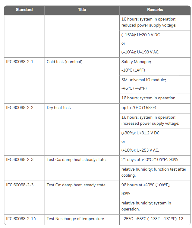
Safety standards: comply with IEC 61508 (functional safety), IEC 61511 (process industry SIS), ISO 13849-1 (mechanical safety), UL 508 (industrial control equipment), etc;

Hazardous Area Certification: ATEX, IECEx (Ex nA IIC T4, applicable to Zone 2 areas), FM 3611 (Class I/II Division 2 hazardous areas, such as chemical explosive environments);

Environmental Protection and Electromagnetic Compatibility: Compliant with RoHS Directive (Halogen Free Design) and EN 61000-6-2 (Electromagnetic Immunity in Industrial Environments), ensuring stable operation in complex industrial environments.

System hardware composition and core modules

The Safety Manager hardware system adopts a three-layer architecture of “cabinet chassis module”, with core components including cabinet, controller chassis, IO chassis, power module, control processor module, input/output module, etc. The functions and technical parameters of each component are as follows:

(1) Cabinet: Physical carrier of the system

Standard configuration: Based on Rittal TS 8 series cabinets, default protection level IP20, optional IP54 upgrade; Including cooling fans (such as FANWR-24R, 24V DC with status feedback), thermostats (monitoring cabinet temperature to avoid module overheating), grounding bars (ensuring equipment grounding resistance ≤ 4 Ω), lighting fixtures (easy to maintain);

Key parameters: dimensions (such as 80 × 60 × 200cm, 80 × 80 × 200cm), weight (full load ≤ 550kg), operating temperature (-5~70 ℃, remote cabinet -40~70 ℃).

(2) Chassis: Module Installation and Signal Transmission Core

Divided into controller chassis (CPCHAS series) and IO chassis (IOCHAS series), supporting redundant/non redundant configurations to meet different safety level requirements:

Chassis type, model example, core functions, key specifications

Controller chassis CPCHAS-0001 is equipped with a control processor module to achieve system logic operations. It supports 1-2 Control processors, with a height of 4HE and a standard size of 19 inches

Non redundant IO chassis IOCHAS-0001S is equipped with non redundant IO modules, supporting 18 IO modules connected to on-site sensors/actuators, powered by 5V-R (redundant 5V)

Redundant IO chassis IOCHAS-0001R is equipped with redundant IO modules to improve system fault tolerance. It supports 9 pairs of redundant IO modules and a dual IO bus design

(3) Power Supplies: System Stable Power Supply Guarantee

Provide multiple types of power modules, supporting AC-DC conversion and redundant power supply, to meet different voltage requirements (24V/48V/60V/110V/120V DC). The core models and parameters are as follows:

Power supply model, output specifications, core characteristics, applicable scenarios

PSUNI2424 24V DC/24A, 600W dual overvoltage protection (SIL3 compatible), core controller power supply for operating temperature of -40~70 ℃

PSU-UNI2450U 25-28V DC/43-48A UL 508 certification, 100ms power-off hold, supports parallel expansion and high load IO module cluster power supply

FEEDER-24R 24V DC/63A redundant design, with status feedback relay, overcurrent protection redundant system main power feeder

(4) Control Processor Modules: The System’s Brain

QPP-0002 (Quad Processor Pack): Core computing module, dual processors running synchronously, with Flash/RAM storage (battery backup, BKM-0001 module provides battery), supports Watchdog function (monitoring program execution time, memory errors), meets SIL3 requirements;

USI-0002 (Universal Safety Interface): Communication module, providing 2 channels of 10/100M Ethernet and 2 channels of universal serial communication (RS232/485), supporting interconnection with systems such as Expert PKS, with hardware firewall function;

BKM-0001 (Battery and Key Switch Module): A battery and key switch module that includes 2 lithium batteries (backup RAM data, approximately 3 months of battery life), a reset key (clear fault logs), and a forced enable key (allow IO signal forcing).

(5) I/O Modules: Field Signal Interaction

Input module: supports digital/analog signal acquisition, with fault self detection function, core models such as SDI-1624 (24V DC 16 channel digital input), SAI-1620m (16 channel analog input, 0-4V), SDI-1608 (16 channel digital input with ground fault monitoring);

Output module: supports safe digital/analog output, with short-circuit protection, core models such as SDO-0824 (24V DC 8-channel digital output), SAO-0220m (2-channel analog output, 4-20mA);

Converter module: such as BSAI-0420mI (converts 4-20mA to 0-2V, compatible with SAI-0410 module), to achieve matching between on-site signals and module inputs.

Key processes for system installation and maintenance

(1) Hardware Installation Specification

Cabinet installation: Horizontal/vertical installation should meet the requirement of heat dissipation gap (such as reserving 100mm above and below the fan), and grounding should be independent (protective ground and signal ground should be separated);

Module installation: IO modules need to press the “Key Coding” corresponding slot (such as SDI-1624 corresponding to A5/C5 hole positions) to avoid damage caused by incorrect insertion; Redundant modules need to be installed in pairs to ensure synchronous communication;

Cable connection: System interconnection cables (SIC) and communication cables (such as CCI-HSE-01 Ethernet cables) should be wired according to pin definitions to avoid reverse polarity (such as 24V DC power supply “+” connected to pin d8, “0V” connected to pin d10).

(2) Regular maintenance plan

Daily maintenance (daily/weekly): Check the LED indicator light (green normal, red fault), fan operation status, and cable joint tightness; Backup historical data (to USB drive/server);

Regular maintenance (monthly/quarterly): clean the cabinet filter (to avoid dust blockage causing overheating), test the power supply voltage (fluctuation should be ≤± 5%), and measure the cable insulation resistance (≥ 10M Ω);

Annual maintenance: Full module calibration (using original calibration tools such as 9100 calibrator), battery replacement (BKM-0001 module lithium battery replaced every 5 years), firmware upgrade (downloading the latest version from GE Digital official website).

(3) Troubleshooting and Solutions

Based on the “internal system exception” error mentioned in the Nexinstrument document, supplement the general troubleshooting logic of Safety Manager, and organize common troubleshooting solutions in the manual:

Possible causes and solutions for fault phenomena

System error “internal exception”: 1. Control processor program crashes; 2. Power supply voltage fluctuations; 3. Module communication interruption: 1. Check the QPP-0002 module’s Status LED (red indicates hardware failure and needs to be reset or replaced); 2. Use a multimeter to measure the 24V DC power supply (within the range of 20.4-31.2V); 3. Check the communication light of USI-0002 module (Tx/Rx light does not light up, network cable needs to be unplugged again)

IO module has no signal input 1. Sensor failure; 2. Cable breakage; 3. Module calibration expired. 1. Replace sensor for testing; 2. Use a multimeter to measure the continuity of the cable (such as the signal at pin d12 of SDI-1624 module); 3. Recalibrate the module (refer to SAI-1620m calibration process)

Power module alarm (red light on) 1. Overvoltage/undervoltage; 2. Fan malfunction; 3. Overload 1. Check the input voltage (e.g. PSU-UNI2450U input needs to be between 93-253V AC); 2. Check the fan speed (FANWR-24R speed should be ≥ 1500 RPM); 3. Reduce the number of parallel modules to avoid overloading

Communication interruption (with upper computer): 1. IP address conflict; 2. Protocol mismatch; 3. Network cable failure: 1. Reconfigure the USI-0002 module IP (to avoid conflicts with Expert PKS); 2. Confirm the communication protocol (such as Modbus TCP); 3. Replace the network cable and test the link (using a cable tester)

System configuration and expansion

Model coding rules: The hardware model includes a prefix (FS – non coated, FC – coated, FA – explosion-proof), module type (such as SDI-1624), and suffix (version number, such as V1.1), for example, “FC-SDI-1624” represents a coated 24V DC 16 channel digital input module;

Scalability: Supports adding IO channels through IO expansion modules (such as IO-0002), improving power supply reliability through redundant power supplies (such as RUSPSU-R), and achieving on-site signal terminal switching through FTA modules (such as IOTA-R24).

Emerson PR6423 8mm eddy current sensor

The Emerson PR6423 8mm eddy current sensor is a non-contact industrial sensor designed specifically for key rotating machinery such as steam turbines, gas turbines, water turbines, compressors, gearboxes, pumps, and fans. Its core function is to accurately measure the radial/axial dynamic displacement, position, eccentricity, and speed of the shaft, providing reliable data support for equipment status monitoring and fault warning. It is suitable for high-precision monitoring of rotating machinery in the field of industrial automation.

Core performance parameters

1. Measurement ability

Linear measurement range: 2mm (80 mil), initial air gap (installation reference gap) is 0.5mm (20 mil), ensuring stable data collection within the common displacement range of rotating machinery.

Incremental Scale Factor (ISF): Compliant with ISO standards, 8V/mm (203.2mV/mil), with an error of ± 5% within the temperature range of 0-45 ° C (32-113 ° F), ensuring measurement accuracy under different operating conditions.

Linearity deviation: Within the temperature range of 0-45 ° C (32-113 ° F), the deviation from the best fitted line is ± 0.025mm (± 1 mil), indicating excellent data linearity and reducing measurement errors.

Measurement target requirements: The minimum shaft diameter is 25mm (0.79 inches), and the default target material is 42CrMo4 (corresponding to AISI/SAE 4140) ferromagnetic steel. Other materials can be customized as needed.

2. Environmental and protective characteristics

Protection level: IP66 (compliant with IEC 60529 standard), can effectively prevent dust, strong water spray, and adapt to complex environments in industrial sites.

Temperature adaptability:

Sensor (including 1-meter cable): Operating temperature -35~+180 ° C (-31~356 ° F), resistant to high temperature conditions;

Cable and connector: Operating temperature -35~+150 ° C (-31~302 ° F), matching the overall temperature resistance range of the sensor.

Material selection:

Sensor probe: PEEK polyetheretherketone (resistant to high temperature and chemical corrosion);

Shell: stainless steel (high-strength, rust resistant);

Cable: polytetrafluoroethylene (PTFE, high and low temperature resistance, good insulation);

Connector: Nickel plated brass (low contact resistance, anti-oxidation).

Weight: The sensor (including a 1-meter cable) weighs approximately 100 grams (3.53 ounces), and its lightweight design makes it easy to install on mechanical structures with limited space.

Compliance certification and adaptation to hazardous areas

1. General compliance

CE certification: Complies with the 2014/30/EU (EN 61326-1, Electromagnetic Compatibility), 2014/34/EU (ATEX Explosion proof), 2011/65/EU (RoHS Environmental Protection) directives, and meets European market access requirements.

Basic explosion-proof standards: comply with ATEX and IEC Ex EN 60079-0 (General Requirements for Equipment) and EN 60079-11 (Intrinsic Safety Equipment) standards, providing basic protection for use in hazardous areas.

2. Hazardous area certification (requires cooperation with converters)

The classification of hazardous areas for sensors depends on the accompanying converter (refer to the converter document for details), and their own temperature classification is as follows:

Explosion proof type, temperature rating, upper limit of ambient temperature (Ta)

Intrinsic safety (ia) T6 ≤ 64 ° C

T4 ≤114°C

T3 ≤160°C

No spark (nA) T6 ≤ 64 ° C

T4 ≤114°C

T3 ≤160°C

Structural dimensions and installation design

1. Two installation types

The sensor offers two structures: standard installation (PR6423/xxx xxx) and reverse installation (PR6423/xxxR xxx). The core size parameters are as follows:

Installation type Key dimensions (mm/inch)

Standard Installation – Shell Thread: M10 × 1 or 3/8-24UNF

-Wrench size: M10 thread with SW 11mm, 3/8-24UNF with SW 7/16 inch

-Standard cable diameter: 2.8mm (0.110 inches), minimum bending radius 25mm (0.984 inches)

-Armored cable diameter: 6mm (0.236 inches), minimum bending radius 35mm (1.378 inches)

The threads, wrenches, and cable sizes for reverse installation and standard installation are the same, with only the installation direction and shell layout different, to meet the installation space requirements of specific mechanical structures

2. Cables and connectors

Cable configuration: An adapter plug can be optionally selected after a 1-meter cable, with a cable length tolerance of 0~+10%, and supports customization of different lengths (such as 8.0m, 9.0m, 10.0m, etc.).

Connector type: The default configuration is a 11.0mm (0.433 inch) diameter Lemo male connector, or an open cable end (without connector) can be selected to meet the interface requirements of different monitoring systems.

Model selection and special versions

1. Standard model selection (core parameter combination)

Is the diameter of the probe casing threaded with armor cable model

8mm M10 × 1 No PR6423/00

It’s PR6423/01

Yes (reverse installation, requires adapter plug) PR6423/03*

3/8 “-24 UNF No PR6423/10

It’s PR6423/11

Yes (reverse installation, requires adapter plug) PR6423/13*

*Note: Models with “*” are only suitable for reverse installation with adapter plugs, and reverse installation without adapter plugs is not optional.

2. Special version (PR6423/xxx xxx RAD)

Specially designed for radiation environments, there are differences between technical parameters and standard versions:

Material adjustment: The probe material is changed to epoxy resin, the cable is changed to polyolefin, and the shell is made of stainless steel with EPDM O-ring seal to improve radiation resistance.

Temperature and radiation tolerance: The working temperature drops to -35~+80 ° C (-31~176 ° F); The anti radiation dose of the sensor (including 1-meter cable) reaches 80 Mrad, and the anti radiation dose of the extension cable and converter reaches 0.1 Mrad; At a radiation intensity of 0.5Sv/h, the calculated lifespan is 18.26 years in a neutron radiation environment and 183 years in a beta or gamma radiation environment.

Certification restriction: Non hazardous area certification, only applicable to ordinary radiation environments.

Optional accessories

Model Product Description Purpose

EZ 1600 probe bracket fixes the sensor to ensure precise installation position

MPT 064 metal protective tube protects sensors and cables against mechanical damage

Kongsberg Maritime Seatex DARPS Transponder

Kongsberg Maritime’s Seatex DARPS Transponder is a new generation relative GPS (RGPS) positioning system responder developed based on advanced GPS technology. Its core function is to provide high reliability and precision relative position reference for offshore operation scenarios, such as ship and platform/FPSO loading and unloading operations. Through integrated design and intelligent communication protocols, it adapts to the multi device collaborative positioning requirements in extreme offshore environments.

Core positioning and technological advantages of the product

1. Core application scenarios

Specially designed for offshore operations that require precise relative positioning, with a focus on addressing:

Position monitoring during loading, unloading, and supply operations between ships and fixed platforms (such as FPSOs and offshore drilling platforms);

The relative positioning of multiple ships working together in the same area to avoid operational risks caused by collisions or positional deviations.

2. Key technological advantages

Mature technology accumulation: Kongsberg Seatex has over ten years of experience in the development of GPS maritime tracking systems. The responder integrates continuous iteration of technical experience with the latest GPS developments to ensure positioning stability.

Highly integrated: All electronic components, GPS antennas, and UHF antennas are integrated into a single physical unit, requiring only one power cord to connect and automatically start when powered on, greatly simplifying installation and maintenance.

Anti harsh environment capability: Made of polyethylene shell, electronic components are designed for harsh marine environments, with a protection level of IP68 (able to withstand short-term immersion in 10 meters of water depth), suitable for offshore conditions such as salt spray, humidity, and vibration.

Multi device collaboration capability: Based on the Time Division Multiple Access (TDMA) protocol, it supports up to 24 ships sharing the same UHF frequency, with an update rate as fast as 2 seconds per time, meeting the requirements of multi ship synchronous operations.

Core functions and working principles

1. Relative positioning workflow

Data collection: The responder has a built-in GPS receiver that captures L1 C/A code and carrier phase signals, while also having anti multipath interference function to reduce signal attenuation and ensure the accuracy of the original data.

Data transmission: GPS raw data and responder status parameters are transmitted to the DARPS 100 host system on board via a UHF wireless link (bidirectional communication); If the ship sends RTCM correction data, the responder can output DGPS positioning results, further improving accuracy.

Position calculation: After receiving data, the DARPS 100 system on board accurately calculates the relative position between the ship and the responder (and corresponding platform); A single responder can communicate with multiple ships equipped with DARPS 100 simultaneously, achieving collaborative positioning among multiple ships.

2. Core functional highlights

High precision positioning: Based on L1 C/A code measurement technology, combined with anti multipath interference design, it ensures relative positioning accuracy and meets the strict requirements for position error in offshore operations.

Intelligent data verification: By using reliable data protocols to detect and eliminate erroneous data, invalid results can be avoided from affecting RGPS operations, ensuring reliable positioning.

Remote configuration and monitoring: Key parameters of the responder (such as UHF frequency, GPS update rate, TDMA time slot) can be remotely modified through the DARPS 100 control unit or handheld controller on board, and all status parameters (such as power supply, signal strength, working mode) can be monitored in real time to prevent sudden failures.

Flexible frequency selection: Provides two UHF frequency bands (450-470MHz standard band, 868-870MHz optional band), with easily adjustable frequencies within the band to adapt to radio spectrum planning in different sea areas.

Detailed explanation of technical specifications

1. General and GPS parameters

Category specific specifications

General characteristic appearance: polyethylene cylindrical (with mounting bracket adapter); Update rate: up to 1Hz; Protection level: IP68 (10 meter water depth)

Number of GPS performance channels: 12 channels (supporting L1 C/A code and carrier phase measurement); Core function: multi-path interference suppression

2. UHF radio parameters

Parameter specifications

Frequency range standard: 450-470MHz; Optional: 868-870MHz (Synthetic Bidirectional Radio)

Channel spacing of 25KHz

Transmitting power 0.5W

Data transmission rate 9600 bps

Communication distance (line of sight) typically 15-20 kilometers

3. Interface (I/O) and Control

Serial interface: 3 serial I/O lines, maximum baud rate 19200 bps; Support remote configuration of baud rate, TDMA time slot number, UHF radio mode, and GPS update rate.

Control mode: Supports remote reset commands and status message polling; Can connect to handheld terminals for local status viewing and control; Multiple connector options are available (please contact Seatex for detailed information).

4. Physical and environmental characteristics

Physical parameter specifications, environmental adaptability specifications

Size (diameter x height) 150mm x 800mm Operating temperature -10 ° C~+55 ° C

Weight 4.5 kg Storage Temperature -30 ° C~+70 ° C

Power requirement: nominal 9-32V DC, power consumption of 6.5W, humidity tolerance, suitable for high humidity offshore environment

image.png

ABB E max series low-voltage molded case circuit breaker (Sace)

The ABB E max series low-voltage power circuit breaker (Sace) is an innovative product developed based on over half a century of circuit breaker technology. It has high reliability, easy installation, and flexible adaptability. It has passed UL certification and complies with ANSI low-voltage power circuit breaker standards, covering a rated continuous current range of 800A-5000A and a rated short-circuit current range of 42kA-125kA (480V). It is suitable for distribution systems, industrial equipment, and other scenarios, providing efficient power protection solutions for designers, switchgear manufacturers, installers, and users.

Core product classification and key parameters

1. Model and frame specifications

The series includes five models (four sizes): E1, E2, E3, E4, and E6. The differences in core electrical parameters are as follows (taking UL standards as an example):

Model Rated continuous current (A) 480V Rated short-circuit current (kA) Number of poles Installation method Typical weight (kg/lbs, 3 poles fixed)

E1 800-1200 42 3/4 fixed/pull-out 50/110

E2 1200-1600 50 3/4 fixed/extracted 55/121

E3 1200-2500 65-100 3/4 fixed/pull-out 80/176

E4 3200-3600 65-100 3/4 fixed/withdrawable 89/196

E6 4000-5000 85-125 3/4 fixed/withdrawable 125/275

2. General technical specifications (shared by UL and IEC)

Voltage and Frequency: Rated maximum voltage 635VAC, rated operating voltage 600VAC, test voltage (50/60Hz for 1 minute) 2.2kV, applicable frequency 50-60Hz.

Temperature range: Operating temperature -5~+70 ° C, storage temperature -40~+70 ° C, suitable for different temperature zones in industrial sites.

Neutral pole rating: The neutral pole rating for E1-E3 models is 100% of the rated current, and for E4-E6 models it is 50% (special requirements can be consulted with the manufacturer to customize the 100% rating).

Mechanical and electrical lifespan: Mechanical lifespan (under routine maintenance) 20000-25000 operations, electrical lifespan (440VAC) 10000-30000 operations, with a maximum operating frequency of 60 times per hour.

Core functions and structural characteristics

1. Protection and control capability

Release Unit: Standard PR111/P series release, supporting LI (Long Delay Instantaneous), LSI (Long Delay Short Delay Instantaneous), and LSIG (Long Delay Short Delay Instantaneous Ground Fault) protection functions; PR112/P and PR113/P series are optional, suitable for more complex scenarios (such as PR112/PD supporting communication functions).

Operation time: The maximum closing time is 80ms, the maximum opening time (I<short-circuit withstand current) is 70ms, and the maximum (I>short-circuit withstand current) is 30ms. It can quickly respond to faults and reduce equipment damage.

Auxiliary functions: Comes with 2NO+2NC auxiliary contacts (for indication of opening and closing status), spring energy storage/release mechanical indicators, and manual opening and closing buttons; The pull-out model is equipped with a rocking in device with a closed door, a rocking in position indicator, and an anti insertion lock to enhance operational safety.

2. Installation and structural design

Size and Installation: Fixed 3-pole model with a height of approximately 418mm (16.46 inches) and a depth of 302mm (11.89 inches); The pull-out depth has been increased to 396.5mm (15.61 inches), supporting DIN rail or 19 inch rack installation (requires installation kit).

Terminal and wiring: default rear horizontal terminal, optional rear vertical, front terminal and other types (such as “HH” representing rear horizontal and “HV” representing rear horizontal vertical in the model), suitable for different switchgear wiring requirements; The terminal box is integrated with the current transformer (CT) to simplify on-site wiring.

Redundancy and reliability: The pull-out model is designed with a “mobile part+fixed part” separation, supporting hot swappable replacement; Key components such as sliding contacts and trip units have anti vibration capabilities (7.35 m/S ², 5-500Hz) and comply with ISA S71.04 G3 harsh environment standards.

Product configuration and optional accessories

1. Basic configuration classification

According to the operation mode and function, there are mainly two types of products:

Automatic air circuit breaker: including trip unit and current transformer, supporting fault protection such as overcurrent and short circuit, divided into fixed and withdrawable types, suitable for distribution circuits that require automatic protection.

Non automatic air circuit breaker (switch): no trip unit and CT, only used as a manual or electric power switch, also available in fixed/withdrawable type, suitable for simple circuits that do not require complex protection.

2. Optional attachments (UL and IEC compatible)

Attachment category, specific function and model, example usage

Electrical accessories include shunt release coil (KE6S0, 24VDC), closing coil (KE6C6110-120VAC), and spring energy storage motor (KE6M5110-130VAC/VDC) for remote opening and closing and automatic spring energy storage

Mechanical accessory button protective cover (KE6PG), padlock device (KE6PD1), mechanical counter (KE6MC) to prevent misoperation, lock circuit breaker position, record operation times

Additional auxiliary contacts (KE6A15, 15 sets), position indicator contacts (KE6PS1, 5 sets), extended status monitoring signal, indication of withdrawable circuit breaker position

Interlocking and protective mechanical interlocking (KE6MLP, fixed circuit breaker base), transparent front cover (KE6DC, IP54 protection) achieve multi circuit breaker interlocking control and improve dust and water resistance

Test and Diagnostic Handheld Test Kit (K7TUT, suitable for PR111), Configuration Unit (PR010/T) for on-site testing of trip function and configuration of trip parameters

image.png

Model coding rules (taking UL as an example)

Taking “E1S16XXXXXXXXXX” as an example, the key codes have the following meanings to facilitate selection according to requirements:

Frame dimensions: 1=E1 (3 poles), 2=E2 (3 poles), 3=E3 (3 poles), 4=E4 (3 poles), 6=E6 (3 poles); A=E1 (4-pole), B=E2 (4-pole), etc.

Rated current: 08=800A, 12=1200A, 16=1600A, 20=2000A, 32=3200A, 50=5000A.

Breaking ability: B=basic, N=normal, S=standard, H=high, V=extremely high.

Release unit: A=PR111/P-LI, B=PR111/P-LSI, G=PR112/PD-LSI, etc.

Installation method: B=fixed type, D=pull-out type (excluding bracket).

Attachment code: X=no attachment, A=mechanical counter, B=mechanical trip indicator, F=A+B, etc., combined as needed.

Typical application scenarios

Power distribution: used for the main circuit of low-voltage distribution systems, protecting key equipment such as transformers and busbars, and adapting to E4-E6 high current models.

Industrial equipment: provides short-circuit and overload protection for industrial loads such as motors and frequency converters, and E1-E3 small-sized models are suitable for compact layout of switchgear.

Commercial buildings: As the main switch for power distribution, the pull-out design is convenient for later maintenance and replacement.

Compliance and Certification

Safety certification: UL/UL-C certification (applicable to Class I, Groups A-D, Division 2 explosion-proof areas), ATEX certification (Ex nA IIC T4, Zone 2 areas), IEC 60947-2 standard compliance.

Environmental requirements: Compliant with RoHS directive, halogen-free design, reduces harmful substance emissions, suitable for green industrial scenarios.

image.png

Woodhead BradCommunications ™  Direct-Link ™  PROFIBUS-DP

This product is the industrial grade PROFIBUS-DP network interface card series launched by Woodhead (now under Schneider Electric). Its core positioning is to build a direct communication bridge between PC based control applications and I/O devices, supporting multiple hardware forms and operating systems, with high data throughput, flexible configuration, and ease of use. It is suitable for real-time data acquisition and control in industrial automation scenarios.

Core positioning and overall characteristics of the product

1. Core values

Communication intermediary: realizes direct connection between PC based control applications and PROFIBUS-DP I/O devices, supports deterministic I/O data acquisition, and meets real-time control requirements.

Low cost and high compatibility: It belongs to the entry-level industrial communication component, with high cost-effectiveness, modularity, and scalability. It can be easily embedded in computerized systems and adapted to industrial applications of different architectures.

2. Key common characteristics

Protocol support: Covering multiple PROFIBUS-DP protocol modes to meet the needs of different communication roles:

Basic support: PROFIBUS-DP V0 master station (Class 1/2), V0 slave station (active/passive mode);

Advanced support: Only PCI Universal models support PROFIBUS-DP V1 master station (Class 1/2).

Configuration and diagnosis: Equipped with one serial or Ethernet port (depending on the model) for remote configuration and diagnosis; Support automatic detection of network devices, store configuration parameters in Flash memory, and support automatic startup mode.

Performance optimization: onboard embedded communication module improves data throughput; Equipped with intelligent A.D.M (automatic dual port RAM mapping) mechanism, there is no need to configure I/O tags in the dual port RAM of the card, reducing the load on the host CPU; Provide additional functions such as device status, diagnostic information, process data read-write monitoring, software and hardware watchdog, etc.

Compliance: Compliant with RoHS standards (some models have new features), and a member of the PROFIBUS industry organization (PTO, PNO, France Profibus), with guaranteed protocol compatibility.

Hardware model and technical specifications

This series offers three hardware forms that are compatible with different PC bus types. The differences in core parameters are shown in the table below:

Model category: Direct Link ™  PCU-DPIO(PCI-Universal) Direct-Link ™  PC104-DPIO (PC/104 bus) Direct Link ™  CPCI-DPIO (CompactPCI Bus)

Bus and voltage PCI Universal 3.3V/5V, compatible with PCI-X PC/104 bus CompactPCI bus, 5V power supply

Processor AMD SC520133 MHz AMD SC520100 MHz AMD SC520133 MHz

PROFIBUS chip UART High Speed ASPC2 ASPC2

Storage capacity Flash: 4 Mbytes; SDRAM:16 Mbytes Flash:512 Kbytes; SDRAM:8 Mbytes Flash:512 Kbytes; SDRAM:8 Mbytes

Discrete I/O 1-channel optocoupler discrete input (24V AC/DC, 0.25A); 1 watchdog output (floating contact) same as PCU-DPIO same as PCU-DPIO

Dimensions (length x width) 168mm x 107mm (6.61 inches x 4.21 inches) 95mm x 90mm (3.74 inches x 3.54 inches) 100mm x 160mm (3.93 inches x 6.29 inches)

Maximum power consumption 5.5W (1.2A) Maximum 5.5W (1.2A) Maximum 5.5W (1.2A)

Working temperature: 0 ° C (32 ° F)~+65 ° C (149 ° F) 0 ° C (32 ° F)~+65 ° C (149 ° F) 0 ° C (32 ° F)~+65 ° C (149 ° F)

Storage temperature -40 ° C (-40 ° F)~+85 ° C (185 ° F) -40 ° C (-40 ° F)~+85 ° C (185 ° F) -40 ° C (-40 ° F)~+85 ° C (185 ° F)

PROFIBUS interface 9-pin D-Sub female head, RS485 optical isolation (500V) standard HE13 (2 × 5 pins), optional 9-pin D-Sub female head; RS485 optical isolation (500V) 9-pin D-Sub female head, RS485 optical isolation (500V)

Configure Ethernet port (10/100 Mbps, RJ45 interface) Asynchronous serial port (RS232, 2 signals) Asynchronous serial port (RS232, 2 signals)

LED indicator light PROFIBUS: 2 dual color lights (bus fault/communication status); Ethernet: 4 lights (TX/RX/Link/100Mbps) PROFIBUS: 2 dual color lights; Serial port without additional indicator lights PROFIBUS: 2 dual color lights; Serial port: 2 lights (TX/RX)

RoHS Compliance Yes (New Feature) No Yes (New Feature)

image.png

Additional notes

PROFIBUS speed: All models support adjustable speeds ranging from 9.6 kbps to 12 Mbps, in compliance with the EN 50170 standard.

Plug and Play (PnP): PCU-DIPIO and CPCI-DPIO support hardware PnP, while PC104-DPIO requires manual address configuration (address range C8000~DE000, single card occupies 8 Kbytes).

Protocol Function Details

1. PROFIBUS-DP main station features (all models support V0, PCU-DIPO additionally supports V1)

Main station type core function

DP-V0 Class 1 optimizes the I/O data exchange with the slave station to ensure real-time performance.

DP-V0 Class 2 implements slave diagnosis, reads slave I/O data, writes data blocks (Class 1/2), and terminates data block communication (Class 2).

DP-V1 Class 1/2 is only supported by PCU-DPIO, expanding the functionality of the main station and adapting to more complex communication requirements.

Common capability can connect up to 126 slave stations; Support direct access to variable types such as bit, byte, word, and doubleword; It can share the bus with other main stations in the network, and supports up to 122 bytes of input/output data consistency.

2. PROFIBUS-DP slave characteristics (only supports passive mode)

Access mode: DP-V0 slave passive mode, does not manage PROFIBUS tokens.

Memory configuration: Input/output memory size can be configured (0-244 bytes).

Address and format: The slave address can be configured through software (0~126); The data format supports Intel or Motorola formats.

Limitations: The “Set_Slave_Address” and “Extended Diagnostic” functions are not supported; Provide GSD files (included with CD-ROM) for system integration configuration.

Software Support and Tools

1. Compatible with operating systems

Covering mainstream and industrial specific operating systems to meet the needs of different control scenarios:

Standard Windows: 32-bit Windows XP SP1/2000 SP4/NT SP6/2003 Server;

Embedded systems: Windows XP Embedded, QNX, VxWorks, Linux, Phar Lap ETS, DOS;

Real time extension: Ardence RTX (hard real-time extension).

2. Software suite (included in standard packaging)

Configuration and Diagnostic Console: A core tool that supports graphical interface operations, with features including:

Parameter configuration of cards, networks, and fieldbus devices;

Dynamic network diagnosis, definition of I/O data access items (adapted to OPC servers, ActiveX controls, and other interfaces);

Automatically detect cards inserted into the host, manage user configuration (create/backup/restore), and manually/automatically configure devices;

PROFIBUS scanning (automatic detection of connected slave stations and configuration), GSD library management (adding/deleting GSD files);

Card status indication (quick view of initialization status), troubleshooting and testing.

Data Server and Driver:

Multi protocol OPC server (supporting DA 3.0/2.05), ActiveX controls, DAServer, FastDDE/SuiteLink server;

I/O libraries (DLLs), Ardence RTX real-time extension libraries, and non Windows OS static libraries in the Windows environment;

Software logic package driver, compatible with third-party control software.

Product Model and Description

Part Number Product Description

DRL-DPM-PCU Direct-Link ™  PCI-DPIO: PROFIBUS-DP master/slave (12 Mbps), PCI Universal bus, 3.3V/5V

DRL-DPM-CPI Direct-Link ™  CPCI-DPIO: PROFIBUS-DP master/slave (12 Mbps), CompactPCI bus

DRL-DPM-104 Direct-Link ™  PC104-DPIO: PROFIBUS-DP master/slave (12 Mbps), PC/104 bus

image.png

Schneider Electric EcoStruxure Foxboro ™  DCS Thin Client

This product is a thin client designed specifically for Foxboro distributed control system (DCS) by Schneider Electric, based on HP ®  The T755 hardware platform is equipped with the Windows 10 IoT Enterprise LTSC 2021 system, which enables DCS system monitoring and operation through remote connection in a compact form. It is suitable for traditional and virtualized Foxboro DCS environments, with both ease of use and high security, and supports flexible networking and redundant configuration.

Core positioning and basic configuration

1. Product essence and hardware selection

Definition: A thin client is a physical hardware terminal that accesses the server-side operating system through remote connections, enabling DCS system event monitoring and response. Compared to workstations, it is smaller in size and can be locally deployed on the user side.

Hardware specifications: designated to use HP ®  The T755 model only offers the dual network card (RH103HM) version, and the single network card version has been discontinued; Standard QWERTY keyboard, software installation requires a USB DVD drive (used for installing thin client software, SE RDP connection manager, and alarm keyboard software).

2. Optional configuration (to be purchased separately)

Display device: Supports up to 4 LCD monitors, corresponding to models P0928JJ (23 inch USB touch screen monitor) and RH103FR (24 inch LCD monitor).

Audio and input devices: USB speaker (model RH103DN), up to 4 alarm keyboards (models P0924TT, P0924WV); If the thin client is equipped with a QWERTY keyboard, FoxPanels can be used instead of the alarm keyboard.

Functions and core features

1. Remote access and DCS interaction

Access object: Foxboro DCS software suite can be obtained by connecting to the following remote servers through the network:

H90 and H94 physical servers running Windows Server system;

Virtual machines (VMs) deployed on Foxboro DCS V91 and V95 virtualization hosts.

Communication method: Connect physical or virtual auxiliary communication network (ACN, composed of managed Ethernet switches) through 1GB copper cable Ethernet, Schneider Electric provides dedicated engineering processes for establishing network connections; Supports single or redundant network card connections. If a RDP server failure is detected, it can automatically switch to another server.

Operational capability: As a Human Machine Interface (HMI) station, through Microsoft ®  Remote Desktop Services or SE RDP Connection Manager can remotely view and manage DCS software suites, performing operational tasks similar to workstations.

2. Configuration flexibility

Support multiple deployment configurations to meet different usage scenarios:

Restricted connection: Only allow connections to specific virtual machines or physical DCS servers.

Automatic connection: Automatically connects to a single virtual machine or physical server after booting up.

Redundancy and Multiple Connections: Multiple virtual machines/physical servers can be connected (supporting “one redundancy at a time”), or multiple devices can be automatically connected upon startup; It can also be used in non domain environments of local version Control Core Services and enterprise version Control Core Services.

3. Performance and Capacity Limitations

Session support: A single server running Microsoft Remote Desktop Services can support up to 30 FoxView remote sessions and 10 Control HMI remote sessions; Due to the bandwidth limitation of physical Ethernet ports, the total number of RDP sessions for all virtual machines on the virtualization host server does not exceed 60 (the actual number is affected by the type and number of applications running in the sessions).

4. Network security

Access control: thin clients can be configured to only connect to specific remote servers; The remote server assigns corresponding operation permissions based on the logged in user’s configuration file.

Additional protection: optional Trellix Terminal Security (ENS) enhanced protection, providing advanced threat defense capabilities; When purchasing the T755 thin client, the Trellix ENS license rights for the first 5 years are included, and renewal is required after 5 years.

Reference document: For detailed security specifications and best practices, please refer to EcoStruxure ™  Foxboro ™  DCS Network Security Reference Guide “(document number B0700HZ).

License authorization requirements

Two types of licenses must be met to ensure legal use:

1. Foxboro DCS related licenses

There is no specific hardware or software license for thin clients, and the existing Foxboro DCS software suite license still applies, but the license belongs to the remote server (non thin client).

Both physical servers and virtual machines, as well as the thin clients connected to them, require corresponding Foxboro DCS software suite licenses. The specific license model needs to be determined based on the type of DCS software installed on the server/thin client.

2. Microsoft License

Free session management: Windows Server allows 2 remote access sessions without CAL (Client Access License), used only for management and technical support, and does not occupy local desktop session resources.

Additional RDS CAL License: If you need more remote connections, you need to purchase a Remote Desktop Services (RDS) client access license (formerly Terminal Services CAL), which supports both “per user” and “per device” authorization modes and can be purchased on the BuyAutomation platform. The specific models and specifications are shown in the table below:

Product Number (P/N) CAL Type Quantity

J0202AW RDS 2016 Device License 5

J0202AV RDS 2016 User License 5

J0202EC RDS 2022 Device License 5

J0202EB RDS 2022 User License 5

J0202EF RDS 2022 Device License 1

J0202EG RDS 2022 User License 1

License rules: The “per device” license must be assigned to one device (thin client, computer, portable device) accessing the remote desktop session, and the license cannot be reused after binding the device; The ‘per user’ license needs to be assigned to one user for each access session, regardless of the device used by the user; All RDS CALs must be installed and activated on a licensed server (usually an RDS server), and Foxboro DCS servers do not come with any RDS CALs at the factory.

Hardware and Technical Specifications

1. Hardware structure and interface (HP t755)

Location interface/component function description

Front A: Power (with indicator light) Power switch and status indicator

B: 3.5mm combination headphones/audio interface for connecting headphones or audio devices

C/D: USB-A 3.2 Gen 1 port for connecting external USB devices (such as mice, printers, etc.)

E: USB 3.2 Gen 2 Type C port high-speed USB connection, supports external devices

F: Information label and VESA 100 installation hole panel for viewing device information, supporting VESA 100 standard installation

G: The system bracket supports vertical or horizontal placement

Back H: Display Port 1.2 interface (4) for connecting LCD displays, up to 4 units

I: RJ-45 Gigabit Ethernet interface network connection interface

J: 19VDC power input connected to DC power supply

K: Disassemble the latch of the rear I/O panel and remove the operating components of the rear I/O panel

L: USB-A 2.0 ports (2) for connecting low-speed USB devices

M: USB-A 3.2 Gen 1 ports (2) for connecting high-speed USB devices

N: Blank interface reserved or unused interface

O: Intel network card for network communication, dual network card configuration for redundancy

Core hardware parameters: AMD ®  Ryzen ™  V2546B processor (3GHz reference frequency, up to 3.95GHz acceleration frequency, 2MB cache, 6 cores), 32GB DDR4-3200 SDRAM (maximum transfer rate of 3200MT/s), 256GB flash memory; Integrate one Gigabit Ethernet port and add one plug-in Gigabit Ethernet port, with dual network cards supporting network redundancy.

2. Functional specifications

Category detailed parameters

Operating System Windows 10 IoT Enterprise LTSC 2021

External devices support mouse/trackball (optional), QWERTY keyboard, alarm keyboard, external speakers, touch screen, USB printer (optional)

Built in diagnostics automatically perform self check upon startup

Display performance: 4 DisplayPort 1.2 video ports, maximum refresh rate of 60Hz, over 65000 colors (limited by software), widescreen (16:9) resolution up to 1920 × 1080 pixels (suitable for CCS and CS displays)

One integrated Gigabit Ethernet port and one plug-in Gigabit Ethernet port for network interface; The DCS ACN interface protocol is TCP/IP

The power supply requires an input voltage of 100-240VAC (automatic switching), a frequency of 50-60Hz, and a maximum power consumption of 90W (actual power consumption is affected by software load, peripherals, and environment)

3. Environmental and physical specifications

Environmental adaptability:

Scene temperature range, humidity range, altitude range

Run at 10-40 ° C (50-104 ° F) with 10% -90% (no condensation) and 20% -80% (condensation) for 300m-3km (1000-10000ft)

Storage -30-65 ° C (-22-149 ° F) 10% -90% (non condensing) 300m-3km (1000-10000ft)

Physical parameters:

Dimensions (vertical placement): Height 210mm (8.26 inches), Width 50mm (1.97 inches), Depth 210mm (8.26 inches);

Installation method: desktop placement, VESA 100 standard installation;

Weight: 1297g (2.86 pounds);

Heat dissipation: Under a 90W power supply, the heat dissipation varies under different operating conditions (such as 28.14 BTU/hour in short idle state and 2.73 BTU/hour in sleep state at 100VAC 60Hz).

Compliance: Complies with Section 508 accessibility standards (VPAT report available); For product safety, EMC, and environmental compliance information, please refer to the t755 thin client product information on the HP official website.

GE Digital Energy Hydran 201Ti Transformer DGA Monitor

Core functions and technical features

1. Gas monitoring capability

Sensor technology: using fuel cell type sensors with breathable membranes, in contact with mineral transformer insulation oil through “dynamic oil sampling” technology, without the need for pumps or additional pipelines; Optional 5-year sensor warranty.

Monitoring range and accuracy: The H ₂ equivalent measurement range is 0-2000ppm (volume ratio), with an accuracy of ± 10% ± 25ppm of the reading; Fast response speed, 90% step change only takes 10 minutes.

Gas sensitivity: 100% response to H ₂ (universal fault gas), while sensitive to CO (paper overheating), C ₂ H ₂ (arc discharge), and C ₂ H ₄ (oil overheating), covering all major fault sources of transformers.

2. Display and operation

Equipped with a backlit LCD display screen (2 lines x 16 characters), it can display the dissolved gas ppm value in real time.

Comes with a built-in keyboard that supports device settings and alarm confirmation operations.

3. Communication function

Local communication: Equipped with a USB B-type interface, it replaces the RS-232 interface that has been removed from most on-site laptops, making it convenient to connect to a computer and configure the system locally.

Remote communication:

Analog output: 4-20mA signal (corresponding to 0-2000ppm range), maximum load 10V, insulation level 2000Vac RMS.

Digital output: Through an isolated RS-485 interface, supporting Modbus or Hydran protocols, outputting gas ppm values and hourly/daily gas change rate (ROC).

Dry contact relay: 3 SPDT type relays (C type), 2 for fault gas alarm, 1 for service alarm, rated load: 3A@250Vac or 3A@30Vdc .

4. Alarm and self check

Configurable alarms: Supports two-level gas alarms (Alert warning, Alarm emergency), which can be set based on gas ppm concentration or hourly/daily change rate; Triggering an alarm when abnormal fault gas levels are detected.

Automatic self check: Conduct a self check every 15 days. If power failure, oil valve closure, sensor or battery replacement issues are found, a service alarm will be triggered.

​Installation and compatibility

1. Installation characteristics

Single valve installation design, directly installed on the transformer oil valve without the need for additional pipelines or pumps; Compatible with 1-inch, 1.5-inch, and 2-inch internal thread NPT valves.

The shape is cylindrical, with a diameter of 178mm (7 inches) and a length of 180mm (7 and 1/8 inches); Installation weight 5.6Kg (12 pounds), transportation weight 6.9Kg (15 pounds).

Optional accessories: Non NPT valve adapter, fin heat dissipation adapter (used when the ambient temperature exceeds 40 ° C or the oil temperature exceeds 90 ° C), sensor installation/removal special pipe wrench.

2. Controller and Networking

Can connect optional controllers to build a local network, supports RS-485 “daisy chain” connection, can connect up to 32 controllers or 201Ti devices in series, with a total chain length of up to 1200m (4000 feet), and all devices can be accessed through any controller in the network.

Two types of core controllers:

Ci-1 single channel controller: replicates some human-machine interaction functions (gas value display, alarm button), suitable for use when installing 201Ti in high position valves of transformers. It also leads out alarm relay contacts and analog outputs for easy wiring.

Ci-C four channel controller: capable of receiving gas ppm data from 4 201Ti units, providing a single communication point, no alarm relay, and analog output, suitable for protecting 3 single-phase transformers and 1 backup transformer scenarios.

3. Software compatibility

Compatible with GE’s well-known Perception Fleet software, supporting data download, trend analysis, and management, and operating logic consistent with other GE DGA monitoring devices.

Environmental and power requirements

1. Environmental adaptability

Working environment temperature: -40 ° C to+55 ° C (-40 ° F to+131 ° F).

Working environment humidity: 0-95% RH (non condensing).

Oil temperature at the valve: -40 ° C to+105 ° C (-4 ° F to+221 ° F, requires fin heat dissipation adapter).

Oil pressure at the valve: 0-700KPa (0-100psi), the sensor has anti vacuum capability.

Protection level: NEMA 4X certified, meets IP66 requirements.

2. Power parameters

AC power supply: switchable between 90-132Vac or 180-264Vac, frequency 47-63Hz, maximum power consumption 475VA.

Applicable scenarios

1. Power Utilities

Provide a simple and effective monitoring solution for non critical transformers.

Focus and prioritize the replacement strategy of auxiliary assets to optimize asset management.

2. Industrial Plants

Reduce the risk of production process interruption caused by power failures.

Reduce high production downtime losses and ensure continuous production.

ProSoft MVI56E-MNET/MNETXT module

Product Overview and Core Positioning

MVI56E-MNET/MNETXT is a single slot ControlLogix backplane compatible module that serves as a communication bridge between Rockwell Automation ControlLogix processors and Modbus TCP/IP devices. It supports both Modbus TCP/IP client (Master) and server (Slave) functions, enabling data exchange with Modicon programmable automation controllers (PAC) and various Modbus TCP/IP compatible instruments and devices.

The two models have completely identical functions, only applicable in different environments:

MVI56E-MNET: Targeting standard industrial control scenarios and meeting conventional environmental requirements;

MVI56E-MNETXT: specifically designed for Logix XT ™ Control platform design with conformal coating, capable of withstanding extreme temperatures and corrosive environments, suitable for harsh industrial scenarios such as chemical and outdoor equipment.

Core Features and Advantages

The module reduces the deployment and maintenance costs of industrial communication through its three core features of compatibility, integration, and ease of use, as follows:

Specific description of characteristic categories and core advantages

Backward compatibility is fully compatible with early MVI56-MNET modules, and can be upgraded without modifying existing ladder logic programs or module configurations, avoiding secondary development costs during upgrades and protecting historical investments

The integrated communication function of RSLogix 5000 can be achieved through RSLogix ™  The example additional instructions (AOI) or ladder logic files in 5000 enable seamless integration with the ControlLogix control system, reducing cross platform configuration complexity

Graphic configuration and diagnostic support for ProSoft Configuration Builder (PCB) software, enabling online/offline configuration through high-speed Ethernet ports; Built in CIPconnect ®  Technology can be used across EtherNet/IP through the 1756-ENxT/1756-CNB module ™/ ControlNet ™ Network remote management simplifies the configuration process, supports remote operation and maintenance, and reduces on-site debugging workload

ProSoft Discovery Service (PDS) tool is used for network discovery and IP management, which can quickly locate modules in the network and allocate temporary IPs to solve the problem of complex module IP configuration in industrial scenarios, improving deployment efficiency

Non volatile storage equipped with industrial grade Compact Flash (CF) “personality module”, storage network and module configuration; When a module fails, simply transfer the CF card to complete the replacement, achieving a “plug and play” replacement and reducing system downtime

Intuitive display of 4-character Alpha Numeric scrolling LED screen, displaying module status in plain English IP、 Port information and errors (no obscure code); Paired with ERR/APP/OK three color LED indicator lights, faults can be quickly located, reducing the difficulty of operation and maintenance troubleshooting

Modbus TCP/IP communication capability

The module supports both Client (active initiating communication) and Server (passive receiving communication) modes, covering the bidirectional data exchange requirements between the control end and the device end in industrial scenarios. The specific specifications are as follows:

1. Modbus TCP/IP Server (Slave, server mode)

Connectivity: Supports independent connections between two types of ports, with a maximum of 10 connections per type of port

Service Port 502 (Standard MBAP Protocol);

Service Port 2000 (encapsulation protocol).

Support function codes: Function Code 1 (read coil), 2 (read discrete input), 3 (read hold register), 4 (read input register), 5 (forced single coil), 6 (pre-set single register), 8 (diagnostic), 15 (forced multi coil), 16 (pre-set multi register), 17 (report slave ID), 22 (mask write register), 23 (read/write register).

Data source: Module data can come from ControlLogix processors or other Modbus Server devices in the network (obtained through Client mode).

2. Modbus TCP/IP Client (Master, client mode)

Communication capability: 1 client connection, supports up to 100 instructions, can communicate with multiple server devices; Supports MBAP or encapsulated Modbus message format.

Support function codes: Function Code 1, 2, 3, 4, 5, 6, 7 (read abnormal status), 15, 16.

Control method: The ControlLogix processor can control client behavior in two ways:

Command Control: Actively select the instructions to be executed from the instruction list;

Event Commands: Directly issue commands through ladder logic.

3. Data processing characteristics

Memory Mapping: Supports user-defined data memory mapping for up to 5000 16 bit registers, meeting the needs of large capacity data exchange.

Data flexibility: Modbus data types can overlap in the module’s memory database, and the same data can be read and written at the “bit level” or “register level”; Support floating-point data transfer (including Enron and Daniel) ®  Floating point format).

Software and hardware specifications

1. Hardware specifications

Specification category specific parameters

Backplane compatibility single slot 1756 ControlLogix backplane, supporting local rack and remote rack deployment

Backboard current load 5VDC: 800mA; 24VDC:3mA

Ethernet port (E1) 10/100 Base-T, RJ45 interface (compatible with CAT5 cable); Support automatic cross cable detection; Equipped with Link/Activity LED indicator light

Environmental parameters (operation) – MVI56E-MNET: 0 ° C~60 ° C (32 ° F~140 ° F);

-MVI56E-MNETXT: -25 ° C~70 ° C (-13 ° F~158 ° F) (protective coating+wide temperature design)

Environmental parameters (storage) -40 ° C~85 ° C (-40 ° F~185 ° F)

Impact resistance performance during operation: 30g; non operation: 50g

2. Functional specifications

Data transmission optimization: Transfer data at the maximum I/O image block size to improve throughput and update speed.

Module identification: Recognized as an “I/O module” (non communication module) in the ControlLogix processor, adapted to the system’s native I/O management logic.

Special function support: Through the “block transfer code” in ladder logic, special operations such as module state reading, instruction control, and event instructions can be achieved.

Derivative models: Provide MVI56E-MNETR model (remote rack optimized version), support reducing data block size, and adapt to remote rack bandwidth limited scenarios.

Foxboro ™  I/A Series Model H90 Workstation Server

Product Overview and Core Positioning

Model H90 is a 2U rack mounted server level workstation pre installed with Microsoft Windows Server ®  2008 R2 (64 bit) operating system, with Foxboro as its core positioning ™  I/A Series or Foxboro Control System (FCS) is a “multi-purpose application platform” that simultaneously undertakes tasks such as control station hosting, data collection and monitoring, human-machine interaction (HMI), file services, etc. It supports the distribution of application views to remote clients through a local area network (LAN) and is suitable for central control requirements in industrial scenarios that require high server performance, redundancy, and security.

1. Core functions

Multi role support: It can serve as a control station (running I/A Series/FCS control software), data acquisition station (processing various on-site device data), human-machine interface station (displaying graphic and text information), and also supports file services and enterprise network integration.

Hardware redundancy guarantee: standard redundant hot swappable power supply, redundant hot swappable fan, optional RAID1/RAID5 disk array (including hot spare), to avoid system interruption caused by single point of failure.

Peripheral expansion capability: Supports up to 4 displays (including USB touch screen), 4 USB alarm keyboards (or 2 serial/GCIO alarm keyboards), external USB floppy disk drives, printers, etc., to meet complex human-computer interaction needs.

Security Protection Kit: Pre installed McAfee ®  A complete set of security software, including virus protection, host intrusion prevention, data leakage protection, etc., in compliance with industrial security standards (such as NERC CIP).

2. Basic adaptation requirements

Software dependency: Requires I/A Series S10 software license, supporting I/A Series software v8.2-v8.8 or Control Core Services (CCS) v9.0 and above versions; Pre installed with the latest version of Symantec System Recovery (SSR) Server Edition software, supporting system backup and recovery.

Network connection: Connect to the Mesh network of I/A Series/FCS through dual PCIe Ethernet cards, and also connect to non control information networks through two integrated Ethernet ports (subject to standard security specifications).

Key features and technological advantages

1. Core Features

Specific description of characteristic categories

The high-performance hardware configuration is equipped with Intel Xeon 5650 processor, standard with 4GB ECC DDR-3 SDRAM (expandable to 12GB, up to 24GB in dual CPU configuration), internal storage supports up to 8 300GB hard drives (total capacity 2.4TB), supports SAS interface and RAID array, meeting the high requirements of industrial control for computing power and storage.

Full redundancy design – power supply: 2 750W hot swappable redundant power supplies (100-240VAC wide input);

-Heat dissipation: Redundant hot swappable fans to avoid overheating and shutdown;

-Storage: RAID1 (mirror)/RAID5 (distributed parity) disk array, optional hot spare to prevent data loss;

-Network: Dual network cards are redundantly connected to the Mesh network to ensure communication continuity.

Industrial grade security protection based on McAfee ®  Building multi-layered protection with software suite:

-VirusScan with AntiSpyware Enterprise: Real time scanning and killing of viruses and spyware, automatic updating of virus databases;

-EPolicy Orchestrator (ePO): Centralized management of all McAfee products, unified distribution of policies and updates;

-Host Intrusion Prevention (HIP): Proactively intercepting zero day attacks and unauthorized access, supporting port control and application blacklisting;

-Data Loss Prevention (Device Control): Control the hardware ports (floppy drives, optical drives, USB, etc.) of Windows 7 workstations to prevent data leakage.

Flexible remote expansion support enables remote deployment of peripherals through Remote Graphics Unit (RGU):

-Adopting fiber optic transmission, supporting 62.5/125 μ m multimode fiber (up to 70m) or 50/125 μ m multimode fiber (up to 150m);

-It can remotely connect 4 monitors and 5 USB devices (keyboard, mouse, touch screen, etc.) to meet the deployment requirements of separating the control room from the equipment site.

2. Differences from ordinary industrial workstations

Comparison item Model H90 server ordinary industrial workstation

Hardware redundant power supplies, fans, storage, and networks are mostly single power supplies and single hard drives, with no redundancy

Performance limit: Xeon processor, up to 24GB memory, 2.4TB storage mostly for Core processors, 8GB memory limit

The security suite comes pre installed with McAfee’s complete set of industrial security software, basic antivirus software, and no intrusion defense

Remote extension supports RGU fiber optic remote (up to 150m) and only supports short distance wired connections (<10m)

Applicable scenarios: Central control station, multi client data server, local single user operation station

Hardware configuration and expansion specifications

1. Basic configuration and optional extensions

Configuration Category Basic Configuration Optional Extension

Processor Intel Xeon 5650 dual CPU configuration (requires corresponding motherboard)

4GB ECC DDR-3 SDRAM expandable to 12GB (single CPU)/24GB (dual CPU)

Store one 300GB internal hard drive and up to eight 300GB hard drives per SATA CD-RW/DVD drive; RAID1/RAID5 array+hot spare disk

Graphics card dual port DisplayPort/DVI PCIe graphics card (up to 1600 × 1200 resolution) dual/four port graphics card (analog/digital, up to 1920 × 1080 resolution)

Four integrated 10/100/1000Base-T Ethernet ports on the network; Dual PCIe Ethernet network card (Mesh network) with additional copper/fiber Ethernet adapter card

2 USB ports in front and 2 ports behind the peripheral interface; 1 serial interface (GCIO/printer); VGA video port dual serial/single parallel port card; GCIO interface module (up to 2); USB hub

The monitor supports 19/20.1/23/40 inch LCD monitors with USB touch screens (up to 4 units); RGU Remote Graphics Unit

2. Remote Graphics Unit (RGU) specifications

RGU is the core remote extension component of H90 server, used to achieve remote separation and deployment of peripherals and servers. The key parameters are as follows:

Specific specifications of RGU parameters

Model Options: Dual Port Kit (P0928DU), Four Port Kit (P0928DV)

Component RGU unit (P0928DS), PCIe adapter card (P0928DT), 15m LC/LC fiber patch cord (P0972TP)

Transmission distance -62.5/125 μ m multimode fiber: up to 70m;

-50/125 μ m multimode fiber: up to 150m;

-Single mode 9/125 μ m fiber: up to 1000m (user provided)

Interface capability: 5 USB 2.0 ports (including 1 BIOS level keyboard port), 4 DisplayPort video ports, audio input/output/microphone interfaces

Environmental adaptation working temperature 0-55 ℃, relative humidity 20% -80% (no condensation), anti vibration meets NEBS Level 3 (earthquake zone 4)

Environmental and Compliance Specifications

1. Environmental parameters

Environment category, operating conditions, storage conditions

The temperature ranges from 10-35 ℃ (50-95 ℉), and for every 305m increase in altitude, the upper temperature limit decreases by 1 ℃ (up to 3050m) -30-60 ℃ (-22-140 ℉)

Relative humidity 10% -90% (non condensing), wet bulb temperature ≤ 28 ℃ 5% -95% (non condensing), wet bulb temperature ≤ 38.7 ℃

Vibration operation: 0.26G (5-350Hz); Storage: 1.54G rms (10-250Hz)

Impulse operation: 31G half sine impulse (2.6ms); Storage: 71G half sine shock (2ms), 27G square wave shock

The pollution level complies with ISA S71.04 Class G1 (mild pollution) and is suitable for ordinary industrial environments

2. Compliance certification

Specific standards for certification categories

Safety Certification – United States: UL ®  1950;

-Canada: CSA ®  C22.2 No. 60950-1;

-EU: TUV EN60950-1

Electromagnetic Compatibility (EMC) – Canada: ICES Class A;

-EU: CE EN55022 Class A, EN55024, EN61000-3-2/3;

-Laser safety: 850nm laser complies with 21CFR Subpart J Class 1

Industrial security standards support NERC CIP compliance and meet industrial control network security requirements through McAfee security suite

Installation and deployment requirements

1. Physical installation

Rack specifications: 2U height rack mounted design, standard rail kit, to be installed in commercial cabinets with a depth of ≥ 1000mm (39.4in) (ensuring front and rear ventilation and cable space), not compatible with Invensys standard industrial cabinets (such as Industrial Enclosure 32).

Cooling requirements: The cabinet should provide sufficient ventilation to ensure that the internal ambient temperature does not exceed 35 ℃ (95 ℉), to avoid fan failure or performance degradation caused by high temperatures.

Remote deployment: Remote separation of servers and peripherals can be achieved through RGU, with displays directly connected up to 100ft (approximately 30m) and RGU fiber optic connections up to 150m (50/125 μ m fiber optic).

2. Domain controller configuration

If centralized security management (such as user authentication and policy distribution) needs to be enabled, one H90 needs to be configured as the primary domain controller (running Microsoft Active Directory), and it is recommended to pair it with one backup domain controller (to avoid single point of failure).

The domain controller needs to be dedicated and cannot run I/A Series/FCS applications or remote desktop services. Only McAfee ePolicy Orchestrator deployment is allowed.

The system defaults to creating organizational units (OUs), security groups, and group policies. For detailed configuration, please refer to the “Security Enhancements User’s Guide” (B0700ET).

Foxboro ™ I/A Series FBM222 Analog Input Module

Product Overview and Core Positioning

FBM222 is a 16 channel highly integrated analog input module with core functionality for Foxboro ™  The I/A Series distributed control system (DCS) collects 4-20mA analog signals on site (supporting two-wire/three wire transmitters), while using HART ®  The protocol (digital communication superimposed on 4-20mA signal) enables bidirectional data exchange with on-site devices (such as reading device diagnostic information and configuring parameters). It is positioned as a “high-density, high reliability analog signal+HART digital signal integrated acquisition center”, suitable for the needs of batch collection of sensor/transmitter data in industrial scenarios such as petroleum, chemical, and power.

1. Core functions and compatibility

Dual compatibility of signals: All 16 channels support “4-20mA analog signal” and “HART ®  Digital signals “can be mixed and connected to different types of on-site devices (without the need for additional hardware switching).

HART communication capability: As a HART host, it supports HART protocol v5/v6/v7 version devices and can execute HART universal commands, common commands, and device specific commands (with Field Device Expert for HART tool), but does not support HART burst mode.

Basic adaptation requirements: It is necessary to use I/A Series software v8.2-v8.8 or Control Core Services (CCS) v9.0 or above, and connect to the Fieldbus communication module (FCM) or control processor (FCP) through a redundant 2Mbps fieldbus to achieve data upload and instruction issuance.

Power supply flexibility: Supports “internal module power supply” (providing 24VDC power supply for two-wire transmitters) or “external independent power supply” (compatible with three wire devices), and signal crosstalk needs to be suppressed through Cable Balun modules when external power is supplied.

Key features and technological advantages

1. Core Features

Specific description of characteristic categories

Full isolation protection achieves triple isolation: 16 channels are isolated from each other, channels are isolated from module logic circuits, and channels are isolated from ground. It can withstand 600VAC common mode voltage for 1 minute (without damage), completely avoiding signal interference and equipment burnout risks.

High precision acquisition adopts Sigma Delta (∑ – Δ) analog-to-digital converter, with a data update cycle of 100ms per channel. The accuracy of analog acquisition meets the industry’s high standards, meeting the requirements of process control for real-time and accurate data.

The harsh environment adaptation shell is made of extruded aluminum material, which meets the Class G3 (harsh industrial environment) requirements of ISA S71.04 standard. It can withstand complex scenarios such as dust, humidity fluctuations (5% -95% non condensing), and sudden temperature changes (-20~70 ℃).

Hot swappable and easy to maintain support “with hot swappable”, allowing for module replacement without disconnecting field wiring, power supply, or communication bus; The front of the module is equipped with LED indicator lights (running status, bus activity, channel communication status), which can intuitively locate faults.

Communication redundancy ensures access to a redundant 2Mbps fieldbus (A/B dual path), which automatically switches to the backup path in case of a single path failure without communication interruption, ensuring data collection continuity.

2. Special component: Cable Balun module

When multiple channels are powered by an external common power source, a Cable Balun module is required to maintain the balance of the HART communication line and prevent near end crosstalk (this component is not required for internal power supply channels). The core parameters are as follows:

Specific specifications of component information

Model CBM-4

Part number RH903SV

Each module contains 4 Balun units (1 unit corresponds to 1 external power supply circuit), with a maximum increase of 30 Ω in circuit resistance to suppress signal interference

If the hazardous environment adaptation is used in hazardous areas (such as Zone 2), it is necessary to use intrinsic safety barriers (such as MTL 787S+) to limit the energy of the line; External power sources can be connected in parallel with redundant power sources. It is recommended to use capacitors to filter out AC interference

Functional and Performance Specifications

1. Signal and communication parameters

Parameter category specific specifications

HART device compatibility supports HART ®  On site devices for protocol v5, v6, and v7 versions

Internal power supply of input resistor (including terminal components): 302 Ω; External power supply: 282 Ω

Internal power supply output 24VDC ± 10%, output impedance 20 Ω (including terminal components), single channel current limit < 37mA (anti overcurrent)

Fieldbus communication redundancy of 2Mbps, bidirectional communication with FCM/FCP, with a maximum communication distance of 1.2km (without repeaters)

Channel capacity of 16 independent analog input channels, supporting mixed access of two-wire/three wire devices

2. Power supply and power consumption

Power parameter specifications

Input voltage 24VDC (redundant power supply), allowing+5%/-10% fluctuation

Maximum power consumption 10.8W

Maximum heat dissipation 7.2W

3. Calibration requirements

The precision calibration of the module and supporting terminal components (TA) has been completed at the factory, and there is no need for regular on-site calibration, greatly reducing maintenance workload (only confirming basic parameters after module failure replacement).

Hardware and installation specifications

1. Core hardware components

Component type, model/part number, key parameters

FBM222 module RH927AJ weight: approximately 340g (12oz); Dimensions: Height 102mm x Width 114mm (including installation ears) x Depth 104mm

Terminal component (TA) RH924JH material: polyamide (PA, temperature resistance -20~70 ℃); Wiring type: compression terminal; Weight: Approximately 181g (0.40lb); Adapt to 16 channel signal access

Terminal cables are divided into two types of materials:

-Polyurethane/PVC (Type 1 P/PVC): suitable for conventional industrial environments;

-Low Smoke Zero Halogen (Type 1 LSZH): Suitable for scenarios with requirements for smoke toxicity and corrosiveness (such as subways, data centers)

Cable interface module side: 37 pin D-subminiature (D-type) interface; TA side: 25 pin D-subminiature interface

2. Installation requirements

Specific requirements for installation category

The module installation needs to be installed on a 200 series standard modular base plate (such as RH101KF), which supports horizontal/vertical DIN rail installation or can be adapted to a 19 inch rack through an installation kit; Can be installed on the same substrate as other 200 series FBM modules

TA can be installed independently on 32mm or 35mm DIN rails, and can be installed in the same cabinet or adjacent cabinets with the module (the terminal cable supports a maximum length of 30m)

The wiring specifications support solid/multi strand wires (wire diameter 0.2~4mm ²/24~12AWG), and multi strand wires with wire ears (wire diameter 0.2~2.5mm ²) can also be adapted

Environmental and Compliance Certification

1. Environmental parameters

Environment category, operating conditions, storage conditions

Temperature -20~70 ℃ (-4~158 ℉) -40~70 ℃ (-40~158 ℉)

Relative humidity 5%~95% (no condensation) 5%~95% (no condensation)

Altitude operation: up to 3000m; storage: -300~12000m

The anti pollution level complies with ISA S71.04 Class G3 and has passed the EIA 364-65A Class III mixed gas exposure test (withstanding a corrosive environment for 10 years)

Anti vibration 0.75g (frequency 5-500Hz)-

2. Compliance certification

Specific standards for certification categories

Electromagnetic compatibility (EMC) complies with EU Directive 2014/30/EU, EN 61326-1:2013 Class A (Emission and Industrial Immunity)

Product Safety – USA/Canada: UL/UL-C certification, applicable to Class I A-D Group 2, T4 temperature code cabinet systems;

-EU: Low Voltage Directive 2014/35/EU, ATEX Directive 2014/34/EU (DEMKO certified Ex nA IIC T4, suitable for Zone 2 hazardous environments)

International Safety IECEx Certification (compliant with IEC 60079 series standards)

Environmental compliance complies with the EU RoHS Directive 2011/65/EU and revised versions 2015/863, 2017/2102 (restricting the use of hazardous substances)

California Proposition 65 products contain lead and lead compounds, which may cause cancer or reproductive harm. For more information, please refer to www.P65Warning.ca.gov

Terminal Cable Selection Table

Terminal cables are classified by material and length, and commonly used specifications are as follows (can cover installation distances of 0.5-30m):

Length (m/ft) Type 1 Polyurethane/PVC Cable (Part Number) Type 1 Low Smoke Zero Halogen (LSZH) Cable (Part Number)

0.5/1.6 RH916DA RH928AA

1.0/3.2 RH916DB RH928AB

2.0/6.6 RH931RM RH928AC

3.0/9.8 RH916DC RH928AD

5.0/16.4 RH916DD RH928AE

10.0/32.8 RH916DE RH928AF

15.0/49.2 RH916DF RH928AG

20.0/65.6 RH916DG RH928AH

25.0/82.0 RH916DH RH928AJ

30.0/98.4 RH916DJ RH928AK

Search for products

Back to Top
Product has been added to your cart