MControl (1TGE120011R1000) is an integrated control unit designed by ABB specifically for the MNS iS low-voltage motor control center (MCC). Its core function is to achieve motor start stop, operation status monitoring, and feeder circuit control. As the core control component of the MNS iS system, it is suitable for centralized management of low-voltage motors (such as pumps, fans, and conveyor belt motors) in the industrial field, improving the reliability and integration of motor control. The basic information is as follows:
Product identification:
Product ID (Order Number): 1TGE120011R1000
Product Type: MControl (Standard), Motor&Feeder Control Unit
System: MNS iS Low Voltage Motor Control Center (classified under the IEC Low Voltage Motor Control Center category)
Core application: Integrated motor control (such as direct start, overload protection signal interaction) and feeder circuit management, providing modular and standardized control units for MNS iS systems, simplifying the design and maintenance of motor control circuits.
Physical specifications and dimensions
Specification category parameter value description
Product net width 53 mm module horizontal width, compatible with MNS iS system standard installation spacing
The net height of the product is 125 mm, and the vertical height of the module is compatible with the installation space of MNS iS cabinet
The net depth/length of the product is 260 mm. The dimensions of the module along the installation depth direction, including the protruding part of the connector
The net weight of the product is 0.7 kg, excluding the net weight of the packaged module. The lightweight design facilitates cabinet assembly
Ordering and Origin Information
Minimum order quantity: 1 piece (single module independent ordering, supports bulk procurement according to system requirements)
Origin: Czech Republic (compliant with ABB European production standards)
Ordering precautions: It should be used as a supporting component for the MNS iS low-voltage motor control center. When ordering, it is necessary to confirm system compatibility (such as MNS iS cabinet model, motor power level) to avoid functional abnormalities caused by compatibility with non compatible systems.
Compliance and Recycling Classification
Specific description of compliance category
WEEE classified products are not within the scope of WEEE (Waste Electrical and Electronic Equipment) and do not need to be recycled according to the WEEE directive (presumably because they belong to integrated components of industrial control systems and are uniformly recycled with the overall system)
CE certification provides a declaration of conformity in accordance with the CE directive (document number: 1TGE097001), meeting the requirements of the EU Low Voltage Directive (2014/35/EU) and the Electromagnetic Compatibility (EMC) Directive (2014/30/EU)
Supporting documents and technical resources
The official provides multiple technical documents to support product installation, debugging, and maintenance. The core documents are shown in the table below:
Document type Document number Core purpose
Operation and Manual 1TGC910283M0202 Product Installation Steps, Local Operation Guide, Safety Precautions
Operation and Manual 1TGC910001B0204 System Integration Instructions and Wiring Specification with MNS iS Cabinet
Operation and Manual 1TGC910809M0202 Fault Diagnosis Process and Common Problem Troubleshooting (such as Abnormal Motor Start Stop and Signal Loss)
The technical data sheet does not indicate specific numbers (classified as “Popular Downloads”). Detailed technical parameters (such as power requirements, input/output signal types, protection functions), environmental adaptability indicators are included
System adaptability and application scenarios
(1) Product classification
This product belongs to ABB’s “Low Voltage Products and Systems” category, with the specific classification path being: Low Voltage Products and Systems → Low Voltage Systems → IEC – Low Voltage Motor Control Centers → MNS iS, and it is explicitly designated as an exclusive component of MNS iS Low Voltage Motor Control Centers.
(2) Typical application scenarios
Industrial motor control: adapted to MNS iS system, used for low-voltage motor (power usually ≤ 200kW) control in chemical, manufacturing, power auxiliary systems and other fields, such as start stop control and status monitoring of production line fans, circulation pumps, conveyor belt motors;
Feedline circuit management: In addition to motor control, it can also take into account the on/off control of low-voltage feeder circuits (such as lighting and small power equipment power supply circuits), achieving integrated management of “motor+feeder” and simplifying the design of distribution cabinets.
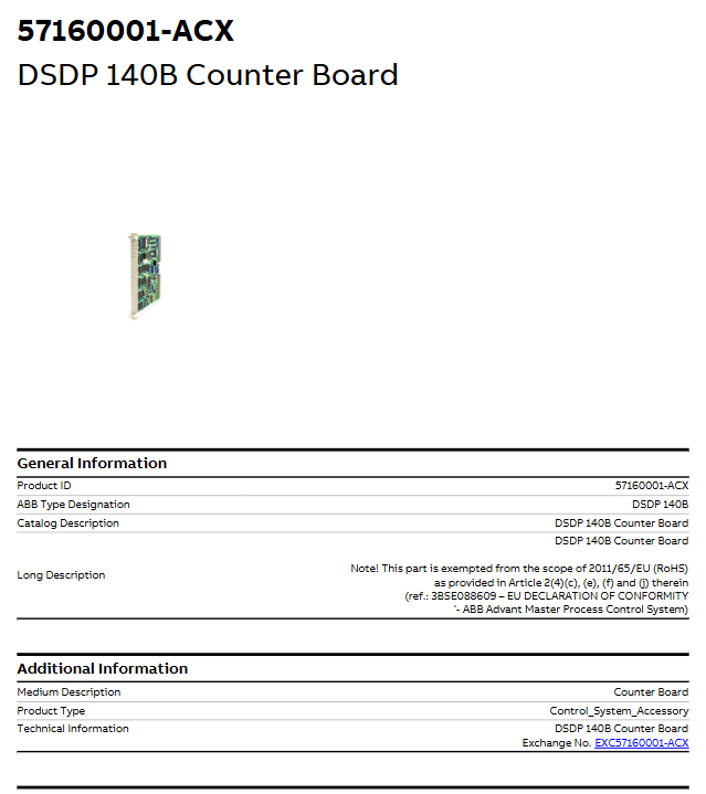
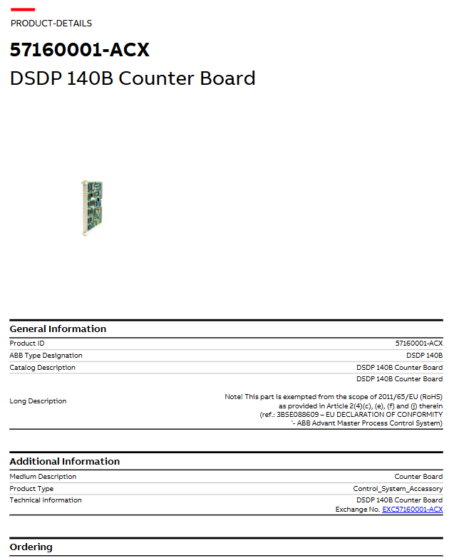
The DSDP 140B counter board is an I/O module accessory designed by ABB for industrial process control systems. Its core function is to implement pulse signal input and counting functions. As a signal acquisition component of the control system, it is compatible with ABB’s multi series process control systems and provides counting support for equipment positioning, flow statistics, and other scenarios. The basic information is as follows:
RoHS Exemption Statement: According to Article 2 (4) (c), (e), (f), and (j) of the EU Directive 2011/65/EU, this product is exempt from RoHS restrictions and complies with the compliance declaration (refer to document 3BSE088609).
Key technologies and physical specifications
(1) Physical dimensions and weight
Specification category parameter value description
Product net depth/length 350 mm module length dimension along installation direction
Product net height 20mm module vertical thickness
Product net width 255 mm module horizontal width
Net weight of product 0.44 kg, net weight of module without packaging
(2) Customs and trade-related codes
HS code: 853890 (classified as “motors, electrical equipment and their parts; recording and reproducing equipment and their parts, accessories for recording and reproducing television images and sounds”, specifically applicable to “parts only applicable to 8535, 8536, 8537 equipment; other”)
Customs tariff number: 85389091
Environmental Compliance and Recycling Classification
Specific description of compliance category
RoHS status complies with EU Directive 2011/65/EU (note: actual exemption status, see basic information above for details)
WEEE classification category 5 “Small equipment” (all external dimensions do not exceed 50 centimeters), which needs to be recycled according to the corresponding category
Number of batteries 0 (the product does not include built-in batteries and does not require separate battery recycling)
SCIP registration information registration number: f26d1193-93ca-433b-ab7a-af0334019897, registration location: Sweden (compliant with the hazardous substance declaration requirements of the EU SCIP database)
System adaptability and application scenarios
The DSDP 140B counter board, as part of the S100 I/O series modules, is widely compatible with ABB multi generation control systems. The specific adaptation scenarios and classifications are as follows:
(1) Supporting kit
It can be used as a component of the “Pulse Input Board Kit” with the matching model 3BSE020832R1 (DSDP 140BK01 Set Pulse Input Board with C), providing a complete solution for integrating pulse input functions.
(2) Classification of adaptive control systems
Specific subsystems/product series of control systems, module categories for adaptation
Control System Products S100 I/O – Modules DSDP 140B Positioning Module
800xA series control system 800xA I/Os – S100 I/O module
Advant OCS (with MOD 300 software) S100 I/O module
Compact Product Suite S100 I/O Module
Its typical application scenario is: as a pulse signal acquisition component in the above control system, it is used for accurate counting in industrial scenarios such as equipment operation frequency statistics, material flow counting, mechanical positioning feedback, etc. (such as production line transmission equipment, metering pumps, conveyor systems, etc.).
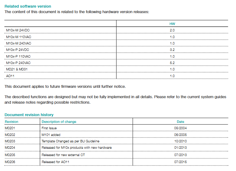
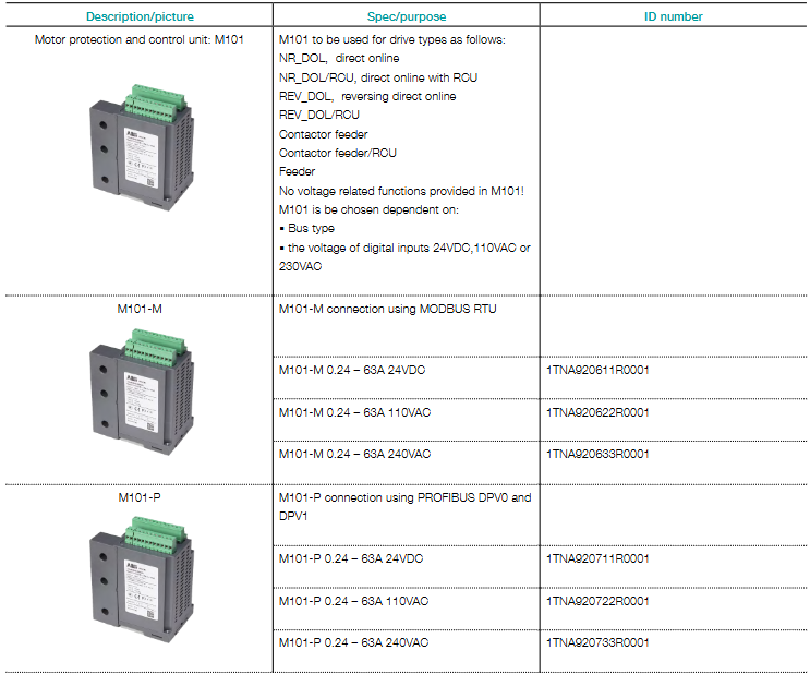
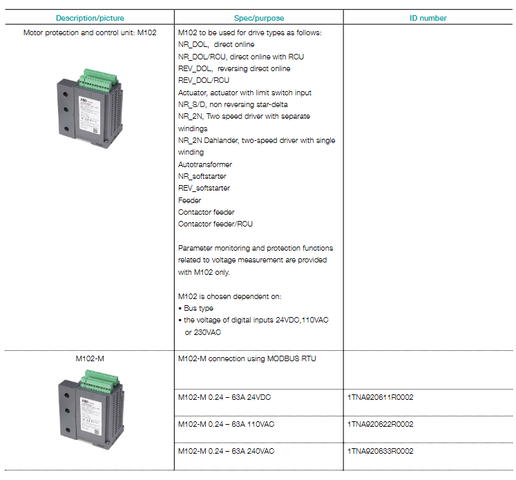
M10x is an intelligent motor control and protection device launched by ABB, which provides an integrated solution of “protection+control+monitoring” for motors based on current/voltage measurement and maintenance data monitoring. Its core value lies in:
Precise protection: covering common motor faults such as overload, grounding faults, and voltage anomalies to avoid equipment damage;
Flexible control: supports multiple drive types such as direct start (DOL), reversible start (REV-DOL), and soft start, adapting to different motor operation requirements;
Intelligent Interconnection: Supports industrial bus protocols such as Modbus RTU and PROFIBUS-DP, and can be connected to distributed control systems (DCS) or PLCs for remote monitoring and parameter configuration;
Scenario adaptation: Suitable for small and medium-sized motors in the industrial field (such as pumps, fans, compressors), especially for scenarios that require high reliability protection and remote control (such as chemical, manufacturing, and power auxiliary systems).
Product classification and core differences
The M10x series is divided into two basic types based on functional complexity, and further subdivided by communication protocol and power specifications. The core differences of each category are shown in the following table:
Classification dimensions, specific types, core functional differences, applicable scenarios
Function type M101 (basic type) – protection based solely on current measurement (such as overload, short circuit);
-No voltage related functions;
-Support basic control (such as contactor feeding, direct start) and simple motor control with only current protection (such as small fans)
M102 (Advanced Type) – Based on current and voltage measurement, with added voltage related protection (such as undervoltage and overvoltage);
-Support complex controls such as soft start and reversible start;
-Support parameter monitoring (such as voltage, power) for motors that require multidimensional protection and complex control (such as process pumps)
Communication Protocol – M (Modbus RTU) supports Modbus RTU protocol (RS485 interface), suitable for small and medium-sized networking (up to 32 nodes per bus) and docking with PLC or local control systems
-P (PROFIBUS-DP) supports PROFIBUS-DP V0/V1 protocol, supports cyclic/non cyclic data transmission, multi master station mode, and is suitable for industrial bus networking to access large DCS systems (such as ABB AC800M, Siemens PCS7)
The power specifications of 24VDC/110VAC/240VAC digital input (DI) voltage are consistent with the power specifications, and 24VDC needs to be matched according to the on-site power supply for DC control system, and 110/240VAC is used for AC power supply scenarios
Core hardware components and accessories
The M10x system consists of a main unit, an operation panel, connecting cables, and optional accessories. The functions, models, and parameters of each component are as follows:
(1) Main unit (core control module)
The main unit is the core of M10x, integrating electronic control circuit and built-in current transformer (CT), with key parameters:
Built in CT range: 0.24~63A (when the rated current of the motor exceeds 63A, an external CT is required);
Installation method: The bottom comes with a DIN rail buckle (supporting horizontal installation), and optional screw accessories can be used for vertical installation;
Digital input (DI): 24VDC/110VAC/240VAC (consistent with power specifications), used for local control signal input (such as start stop commands);
Core model example:
Function Type Communication Protocol Power Specification Model (ID Number)
All M10x main units must be equipped with an operation panel for local monitoring, control, and parameter configuration, which can be divided into two types:
Panel model, core function, adaptation scenario model (ID number)
MD21- with LCD display screen (displaying parameters and fault codes);
-Equipped with LED indicator lights (power, operation, fault);
-Support control buttons (start stop, reset) and navigation buttons;
-Scenario 1TNA920500R0002 (document core model) with mini USB port (for parameter configuration) requiring visual parameter monitoring
MD31- Only equipped with LED indicator lights (without LCD display screen);
-Support basic control buttons and reset;
-Scenario 1TNA920500R0001 with lower cost, requiring only basic status indication and no parameter viewing
(3) Connecting cables
Used for signal connection between the main unit, operation panel, and expansion module (such as AO11), key models:
Cable model, length, interface type, function, usage, model (ID number)
TA201 1.2m RJ11 main unit at both ends connected to MD21/MD31 panel (standard configuration) 1TNA920005R2101
TA204 0.2m two end RJ11 main unit connected to AO11 analog output module 1TNA920005R2106
TK201 2.5m with one end USB and one end mini USB operation panel (MD21/MD31) connected to computer (parameter configuration) 1TNA920005R2102
(4) Optional accessories
Optional expansion components can be selected according to on-site requirements to enhance system functionality:
Accessory Type Core Function Model (ID Number)
Grounding fault CT (RCT) measures residual current to achieve grounding fault protection, supports 1A/5A two rated currents, window diameter 35/70/105mm, 1TNA911005R1001 (LNG35 1A), 1TNA911005R1004 (LNG70 5A), etc
When the external CT motor current is greater than 63A, convert the high current to the built-in CT range (secondary output 5A), support 200/300/500A primary current 1TNA602002R0001(PCT3L200/5R)、1TNA602002R0003(PCT5L500/5R)
The Analog Output Module (AO11) provides 1 channel of 0-20mA/4-20mA analog output (such as motor current, power signal), supporting 24VDC or 110-240VAC power supply 1TNA920511R0001 (24VDC), 1TNA920521R0001 (110-240VAC)
Parameter configuration software (PS201) includes MCUSetup software (parameter download/update), operation manual, GSD file, supports Windows 2000/XP/7/8 1TNA920100R0001
Label paper/USB protective cover MD21/MD31 panel LED label (A4 size, 36 sheets/page), mini USB port protective cover (10 pieces/pack) 1TNA920005R2105 (label paper), 1TNA920005R2107 (USB cover)
Pre configured kits and ordering information
To simplify the selection process, ABB provides pre configured kits (including main unit, operation panel, and standard cables) without the need to order individual components. Common kit models are shown in the table below (taking MD21 panel as an example, MD31 kit model suffix is “R30XX”):
Kit description includes component kit model (ID number)
Model matching: It is necessary to clarify the “functional type (M101/M102)+communication protocol (- M/- P)+power specification (24VDC/110VAC/240VAC)+operation panel (MD21/MD31)” to avoid incompatibility caused by model errors;
Firmware version: The latest firmware version is provided by default. If a specific old version is required, it should be specified in the order;
Accessory selection: When the motor current is greater than 63A, an external CT must be used, and the CT specification should be selected according to the rated current of the motor (such as PCT3L200/5R for 200A motors);
Document requirements: Supporting documents can be requested (such as “M10x User Guide” 1TNC911112D0205, “AO Module Guide” 1TNC920201D0201).
Communication interface RS485 (Modbus RTU/PROFIBUS-DP), baud rate: 9600~115200bps (configurable)
Digital input (DI) 2 channels (24VDC/110VAC/240VAC), used for control commands such as start stop and reset
Working environment temperature: -25~+60 ℃ (operation), -40~+85 ℃ (storage); Humidity: 5%~95% (no condensation)
Protection level: main unit IP20 (to be installed inside the control cabinet); Operation panel IP40 (panel installation)
(2) Compliance certification
Safety certification: UL/CSA certification (compliant with UL 508, CSA C22.2 No.14 standards), IEC/EN 60947-6-2 (specialized standard for motor protection);
Electromagnetic compatibility (EMC): compliant with EN 61000-6-2 (industrial environment immunity) and EN 61000-6-4 (industrial environment emission);
Environmental compliance: Compliant with the EU RoHS Directive (2011/65/EU), restricting the use of hazardous substances.
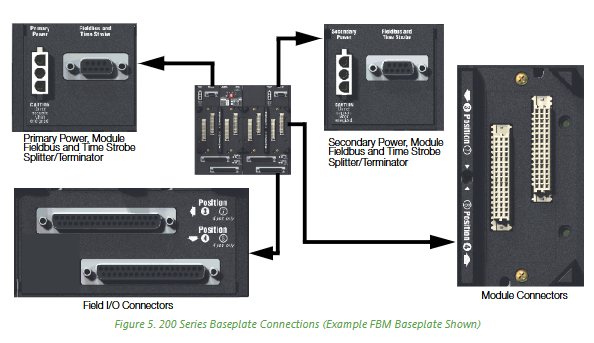
The standard 200 series substrate is Foxboro Evo ™ The core functions of the “hardware connection center” of the system include:
Module carrying and positioning: providing standardized slots for adaptation Field Control Processor(FCP)、Field Device Controller(FDC)、Field Communications Module(FCM)、Fieldbus Module(FBM) Waiting for multiple types of modules to achieve modular layout;
Signal and power distribution: Built in 2 Mbps HDLC redundant serial bus (Module Fieldbus), responsible for data exchange between modules; Simultaneously provide 24V DC redundant power interface to provide stable power supply for all mounted modules;
Redundancy and Scalability Support: Compatible with module level redundancy (such as FCP/FDC redundancy pairs), and supports online addition of substrates (requiring redundant buses) to meet system expansion requirements;
Compatibility Connection: Downward compatible with 100 Series FBM (requiring 268 Kbps fieldbus), upward compatible with Foxboro Evo control network, achieving smooth transition between old and new systems.
Classification and core functions of substrates
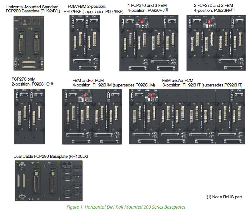
According to the number of slots (2/4/8), installation direction (horizontal/vertical), and supported module types, Standard 200 series substrates can be divided into multiple categories. The core functions and adaptation scenarios of each category are shown in the table below:
FCP280 dedicated substrate 2 horizontal/vertical – single module or redundant for FCP280;
-Supports 4 HDLC fieldbus ports (port 1 can be terminated through DIP switch, ports 2-4 have built-in termination);
-Optional dual cable version (independent A/B bus interface+time synchronization input) RH924YL (standard), RH100JX (dual cable);
Replacing the old CP60 related substrate requires high reliability control for medium to large-scale systems (such as chemical and electrical)
FDC280 dedicated substrate 2 vertical (horizontal orientation needs to be maintained) – single module or redundant pair FDC280;
-Support Ethernet/serial interface (for connecting field devices);
-Horizontal DIN rail installation is required to meet the classification certification RH101KF (unique model) for scenarios where FBM is not needed to directly connect on-site equipment (such as small control units)
FCP270 dedicated substrate 2 horizontal/vertical – single module or redundant for FCP270;
-Reserve installation space for fiber optic splitters/combiners;
-Hardwired address (substrate 0, no ID dialing) P0926HC (horizontal), P0926HW (vertical);
Non RoHS component small and medium-sized system upgrade (replacing old controllers)
FEM100 dedicated substrate 2 vertical – redundant pair for FEM100;
-Expand the number of FBMs supported by FCP270 (up to 4 expansion fieldbuses, each supporting 32 200 Series FBMs) P0973CG (non RoHS), RH924RT (replaces old model) FCP270 system I/O expansion
FBI specific substrate 2 vertical – FBI200/FBI100 redundant pair;
-FBI200 substrate with baud rate selection DIP switch;
-No need for hard wired address (no ID dialing) P0923LR (FBI100, non RoHS), RH924RT (FBI200) fieldbus isolation/filtering (anti-interference requirement scenario)
FCM/FBM universal substrate 2/4/8 horizontal/vertical -2 bits: single module/redundant pair FCM, or 2 FBMs (hard wired address 0, no ID dip code);
-4/8 bits: 4/8 FBMs or 2 FCMs+2 FBMs (including ID dialing, supporting substrate grouping) 2 bits: RH926KE (horizontal), RH926KH (vertical);
4-digit: RH926HM (replacing P0926HM);
8-bit: RH926HT (replacing P0926HT) pure I/O expansion or FCM+FBM combination scenario
-No ID dialing, relying on FCP270 expansion port management P0973CN (non RoHS) FCP270 system for large-scale I/O expansion (such as multi device clusters)
Non RoHS component small system (control+I/O integration, no redundancy requirements)
Key technical characteristics
(1) Module identification and address configuration
The substrate implements the mapping between modules and system software through the * * “Letterbug” string * * (6 bits), and the Letterbug generation rules for different modules are different:
FBM (with FCM): composed of “FCM’s first 4 Letterbug+substrate ID (dial setting)+module physical position (1-8)”;
FBM (with FCP280/FCP270): composed of “custom first 4 digits (not duplicated with FCP)+substrate ID (non FCP280 substrate dialing)+module position+FCP expansion port number (hexadecimal for FEM100 scenario)”;
FCP280/FDC280: Set “Soft Letterbug” through the module panel buttons;
FCP270/FCM100E: Set “Soft Letterbug” through the I/A Series Letterbug configuration tool.
(2) Redundancy and scalability
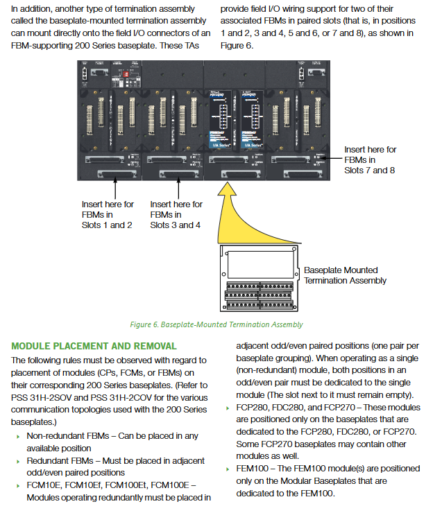
Module redundancy rules:
Redundant FBM/FCM should be installed in adjacent odd/even slot pairs (such as positions 1-2 and 3-4);
Non redundant FCM needs to occupy a pair of slots (adjacent slots are vacant);
FCP/FDC/FEM/FBI redundancy requires the use of a dedicated 2-digit substrate.
Online Expansion:
The system needs to have A/B redundant buses and split the bus signals through a “fieldbus splitter/terminator” (such as RH926KW);
When adding a new substrate, there is no need to interrupt the system operation, only the redundant cables need to be connected to the power supply.
(3) Signal and Communication Specifications
Specification category parameter details
Fieldbus type -200 Series module: 2 Mbps HDLC redundant serial bus (shielded twisted pair);
-100 Series module: 268 Kbps bus (dual axis cable)
Maximum communication distance -200 Series FBM (FBI200): 305 m (2 Mbps);
– 100 Series FBM(FBI200):1830 m(268 Kbps);
-FCP280 directly connected to 100 Series FBM: 915 meters
Time synchronization supports optional GPS time synchronization input (requires splitter/terminator, such as RH924ZQ(FCP280)、RH926KZ(FCM100E/FCP270))
The bus cable between signal isolation substrates is shielded twisted pair to reduce electromagnetic interference (EMI)
Detailed explanation of technical specifications
(1) Electrical and Environmental Specifications
Specification category parameter details
Power requirements – Input voltage: 24 V DC (redundant);
-Cable length: 0.4 m (16 inches) to 2.1 m (7 feet)
Substrate installation kit 19 inch rack installation: including bracket and fasteners P0930AS
(3) Maintain convenience
Hot swappable support: FCP, FEM, FCM, FBI, FBM can all be plugged and unplugged online without disconnecting field cables, power supplies, or communication buses;
Fault diagnosis: Clearly labeled connector functions (power/fieldbus/I/O) on the substrate, combined with module LED indicator lights (such as power and communication status), can quickly locate faults;
Online expansion: Under the redundant bus architecture, when adding FBM support substrates, only A/B bus splitters need to be connected without shutting down.
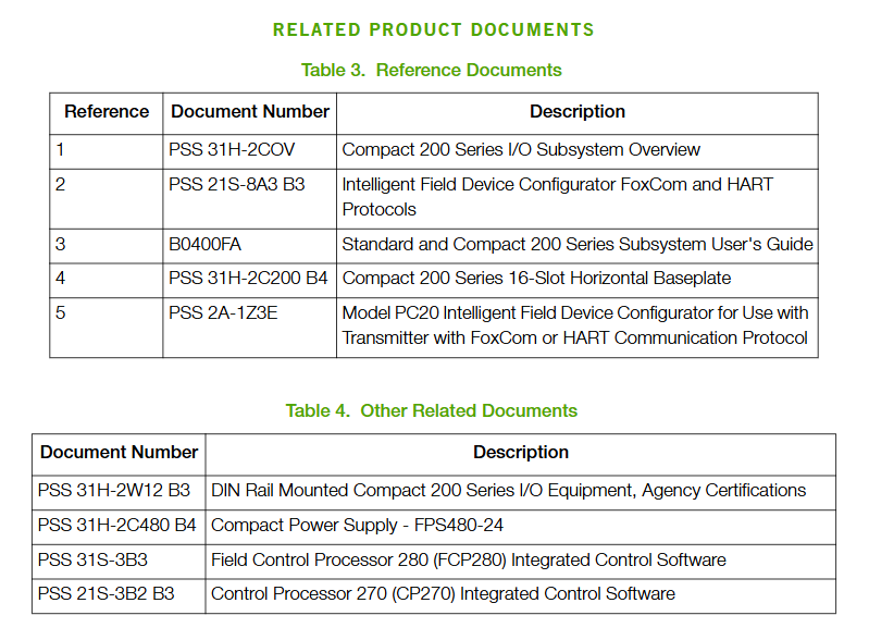
Related reference documents and support
Document type Document number/name Core purpose
Subsystem Overview PSS 31H-2SOV (Standard 200 Series), PSS 31H-2COV (Compact 200 Series) System Architecture and Substrate Matching Rules
The Compact 200 16 slot horizontal substrate is the “hardware backbone” of the Foxboro I/A Series Compact 200 I/O subsystem, with core functions including:
Module support: Provides 16 standard slots for installing Compact 200 series I/O modules (such as analog input/output modules, digital modules, HART communication modules, etc., as previously summarized for FBM218 module);
Signal and power distribution: The internal bus is used to achieve signal interaction between the substrate and various I/O modules, power supply, and communication connection between the modules and the higher-level controller;
Redundancy support: compatible with module level redundancy configurations (such as dual module redundancy), providing hardware foundation for high reliability of I/O subsystems;
Environmental adaptation: Adapt to harsh industrial environments such as dust, vibration, and wide temperature ranges to ensure stable operation of the I/O subsystem.
Structural design and installation characteristics
(1) Physical Structure and Dimensions
Exterior design: Adopting a horizontal layout, the overall structure is made of metal material frame (balancing strength and electromagnetic shielding), with slot markings (1-16) on the surface for easy module positioning and installation;
Key dimensions (refer to Compact 200 series standards):
Length: Approximately 483mm (19 inches, compatible with standard 19 inch cabinet installation);
Height: Approximately 130mm (5.12 inches);
Depth: Approximately 150mm (5.9 inches, including protruding connector);
Weight: Approximately 1.8kg (excluding modules), lightweight design facilitates cabinet assembly.
(2) Installation method and compatibility
Cabinet installation:
Support installation of 19 inch standard industrial cabinets, requiring a dedicated installation bracket (optional accessory), with a reserved installation depth of ≥ 200mm (including module insertion and removal space);
Compatible with “horizontal installation” (default), the installation angle can be adjusted through the adapter (please refer to the system installation guide);
DIN rail installation:
Supports installation with 35mm standard DIN rail (EN 60715 specification), which needs to be fixed with rail buckles, suitable for on-site scenarios without 19 inch cabinets (such as small control cabinets);
Module installation requirements:
Slot compatibility: All 16 slots support all I/O modules of the Compact 200 series, with no signal type restrictions (analog, digital, and communication modules can be mixed for installation);
Redundant module layout: If configuring redundant I/O modules (such as dual FBM218), they need to be installed in adjacent slots (such as slots 3 and 4, 5 and 6), and the first redundant module needs to be located in an odd numbered slot to ensure normal redundant communication and power switching functions.
Core functions and technical features
(1) Power distribution and redundancy support
Power input and distribution:
Supports dual 24V DC redundant power input (requires external redundant power module), with an allowable voltage fluctuation range of+5%/-10% (i.e. 21.6V DC -25.2V DC);
Internally integrated power distribution circuit, stably distributing redundant power to 16 slot I/O modules, with a maximum power supply current of ≥ 1A per module (meeting the power consumption requirements of most Compact 200 modules);
Power protection: Built in overcurrent protection (does not affect the power supply of other modules in case of single channel overcurrent), reverse connection protection (prevents the positive and negative poles of the power supply from reversing and damaging the substrate);
Redundant switching capability:
When the main power supply fails, the backup power supply can seamlessly switch within ≤ 10ms, ensuring that the I/O module has no power interruption and guaranteeing continuous acquisition/output of process signals;
Supporting “module level redundancy” power supply collaboration, redundant modules share the substrate power bus to avoid redundancy failure caused by single power supply failure.
(2) Signal bus and communication connection
Internal signal bus:
Integrate the “control signal bus” and “status monitoring bus”: The control signal bus is used to transmit real-time data (such as 4-20mA analog and digital switch values) between the I/O module and the higher-level controller; The status monitoring bus is used to upload diagnostic information such as module faults and power status;
Bus speed: Control signal transmission rate ≥ 1Mbps, meeting the real-time requirements of industrial processes (delay ≤ 10ms);
Isolation design: Galvanic isolation (isolation voltage ≥ 500V AC/1 minute) is implemented between the signal bus and the power bus to prevent power interference from affecting signal transmission;
External communication interface:
A dedicated “controller connection port” (usually a multi pin industrial connector) is installed on the back of the substrate, which is connected to Foxboro I/A Series controllers (such as Evo controllers) through dedicated cables to achieve overall linkage between subsystems and control systems;
Support redundant communication links (with the cooperation of the controller). When the main communication link fails, the backup link will automatically switch to ensure that data is not lost.
(3) Fault diagnosis and maintenance convenience
Status indication:
The front of the substrate is equipped with LED indicator lights, including a “power status light” (main/backup power, green constant light indicates normal, red flashing indicates fault), a “bus status light” (yellow constant light indicates normal, off indicates bus interruption), and a “module fault summary light” (red light indicates any slot module fault), which facilitate quick judgment of the system status;
Module hot plug support:
All 16 slots support “hot swappable” (the module itself needs to have a hot swappable design). When replacing the I/O module, there is no need to disconnect the power supply or communication cable of the substrate. Simply unlock the module buckle to plug and unplug, reducing maintenance downtime;
Fault isolation:
A single slot is equipped with an independent fault isolation circuit. When a certain I/O module fails, the substrate automatically cuts off the abnormal signal between the slot and the bus to prevent the fault from spreading to other modules or higher-level controllers.
(4) Environmental protection and durability
Anti pollution capability: meets the G3 level (harsh) environmental requirements of ISA standard S71.04, can withstand industrial dust, oil and gas, corrosive gases (such as hydrogen sulfide), and the substrate surface is coated with anti-corrosion coating (such as epoxy resin) to extend its service life;
Resistance to vibration and impact:
Vibration protection: Within the frequency range of 5-500Hz, it can withstand a sine vibration of 7.5m/S ² (0.75g), meeting the installation requirements near vibration sources such as pumps and compressors;
Impact protection: capable of withstanding a 15g (half sine wave, duration of 11ms) impact, suitable for the impact environment of industrial equipment transportation and on-site installation;
Temperature adaptability: Operating temperature range -20 ° C to+60 ° C, storage temperature range -40 ° C to+85 ° C, suitable for most industrial scenarios (such as chemical workshops, outdoor control cabinets).
Detailed explanation of technical specifications
(1) Electrical specifications
Specification category parameter details
Power input voltage: 24V DC (redundant dual input); Voltage fluctuation range:+5%/-10%; Maximum input current: 10A (total power consumption varies with the number of modules)
Maximum output current of a single slot for power distribution: 1A; power bus voltage drop: ≤ 0.5V (at full load)
Signal bus type: differential signal bus; Transmission rate: ≥ 1Mbps; Signal delay: ≤ 10ms
Isolation performance power signal isolation: 500V AC/1 minute; Slot isolation: 600V AC/1 minute
Overcurrent protection single slot overcurrent protection threshold: 1.5A (self resetting, automatically restoring power supply after troubleshooting)
(2) Mechanical and Environmental Specifications
Specification category parameter details
Dimensions and Length: 483mm (19 inches); Height: 130mm; Depth: 150mm; Weight: Approximately 1.8kg (excluding modules)
Installation method: 19 inch cabinet installation (requires bracket), 35mm DIN rail installation (EN 60715)
Working temperature -20 ° C to+60 ° C (non condensing)
Storage temperature -40 ° C to+85 ° C (non condensing)
Working humidity 5% -95% RH (non condensing, temperature ≤ 40 ° C)
Anti vibration of 5-500Hz, 7.5m/S ² (0.75g), in compliance with IEC 60068-2-6 standard
15g shock resistance (half sine wave, 11ms), in compliance with IEC 60068-2-27 standard
(3) Compliance certification
Electromagnetic compatibility (EMC): complies with the EU EMC Directive (2014/30/EU), meets the Class A emission requirements (industrial environment electromagnetic radiation control) and industrial immunity level (anti-static discharge, radio frequency interference, electrical fast transient pulse group) of EN 61326-1:2013 standard;
Security certification:
UL/UL-C certification: suitable for hazardous environments with Class I A-D groups, Zone 2, T4 temperature codes (requires Foxboro I/A Series certified controllers and modules);
ATEX certification: Ex nA IIC T4 Ga, suitable for Zone 2 hazardous environments (such as chemical explosion risk areas);
IECEx certification: compliant with IEC 60079-15 standard, supporting global hazardous area applications;
Environmental compliance: Compliant with the EU RoHS Directive (2011/65/EU), restricting the use of harmful substances such as lead, mercury, cadmium, etc;
Marine certification: Some models have been certified by American Bureau of Shipping (ABS) and Bureau Veritas, meeting the environmental and safety requirements of marine environments such as ship power systems and offshore oil platforms.
Supporting components and reference documents
(1) Key supporting components
Component type, model/specification, core function
The redundant power module is compatible with the Compact 200 series (such as relevant RH models) to provide dual 24V DC redundant power input for the substrate, ensuring power reliability
Installation bracket 19 inch cabinet specific bracket is used for the fixed installation of substrates inside the 19 inch cabinet, ensuring installation stability
Controller connection cable dedicated multi-core industrial cable connection substrate and Foxboro I/A Series controller to achieve data and control signal transmission
Terminal components (TA) such as RH926SP (previously compatible with FBM218) are connected to the I/O modules on the substrate through cables, providing wiring interfaces for field devices
(2) Reference Documents
Document Number/Reference Number Document Name Core Content
31H2C480B4 Compact 200 Series 16 Slot Horizontal Substrate Product Specification Table Detailed Technical Parameters, Installation Dimensions, Electrical Characteristics, Certification Information of Substrate
Overview of PSS 31H-2COV Compact 200 Series I/O Subsystem: Overall Architecture of Subsystem, Matching Rules of Substrate and Module, Redundancy Configuration Scheme
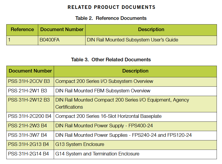
B0400FA standard and Compact 200 series subsystem user guide: substrate installation steps, module insertion and removal operations, fault diagnosis process, daily maintenance precautions
PSS 31H-2C218 FBM218 module product specification sheet (previously summarized document) Detailed specifications of the substrate compatibility module to assist in confirming the compatibility between the module and the substrate
Differences from other Compact 200 substrates (supplementary explanation)
The Compact 200 series substrate includes multiple specifications (such as slot number and installation method), and the core differences between the 16 slot horizontal substrate (related to 31H2C480B4) and other models are as follows:
Comparison dimension: 16 slot horizontal substrate (in this document), 8 slot horizontal substrate (in the same series), vertical substrate (in the same series)
16 slots (supporting more modules, suitable for large I/O subsystems) 8 slots (suitable for small and medium-sized subsystems, saving space) 12 slots (vertical layout, suitable for narrow cabinet scenarios)
Installation method: 19 inch cabinet+DIN rail 19 inch cabinet+DIN rail Only DIN rail (vertical installation, saving horizontal space)
Maximum module power consumption supports total power consumption ≤ 16A (calculated based on a single module 1A), supports total power consumption ≤ 8A, supports total power consumption ≤ 12A
Typical Application Scenarios: Centralized I/O Stations in Large Chemical and Power Systems, Distributed I/O Stations in Small and Medium sized Production Lines, and Space Constrained Sites (such as Outdoor Small Control Cabinets)
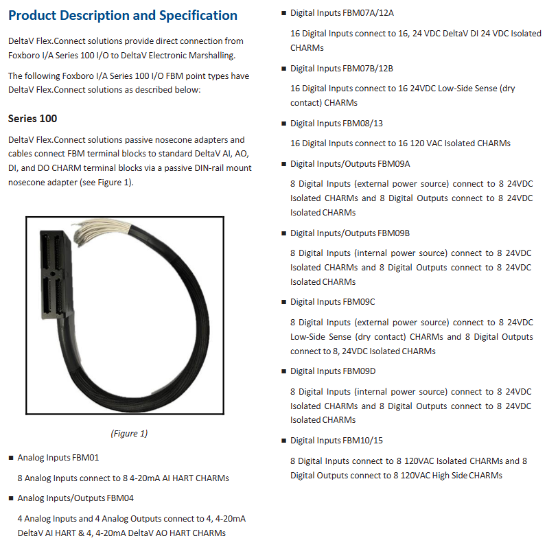
The FlexConnect solution is a modular and scalable connection solution for Foxboro I/A Series 100 I/O systems. Its core value lies in breaking the limitations of traditional I/O systems’ fixed cabinet installation. Through remote/distributed connection capabilities, flexible topology configuration, and high reliability design, it adapts to the complex installation environment and diverse equipment access requirements of industrial sites (such as chemical, petroleum, power, etc.), simplifies wiring, reduces installation costs, and improves the overall maintainability and fault resistance of the system.
System architecture and core components
The FlexConnect solution adopts a layered architecture of “main controller remote I/O unit field device”, with core components including remote I/O modules, communication links, terminal components, and supporting accessories. The functions and collaborative relationships of each part are as follows:
(1) Core components and functions
Component type, key model/specification, core function
The remote I/O module supports Foxboro I/A Series 100 I/O signal types (such as analog input/output, digital input/output, HART communication, etc.) 1. Local acquisition/output of field device signals (such as 4-20mA, discrete signals);
2. Implement signal isolation and anti-interference processing;
3. Bidirectional transmission of data with the main controller through a communication link.
The communication link supports redundant/non redundant Ethernet and dedicated industrial bus to ensure high-speed and stable data transmission between the main controller and remote I/O modules;
2. Redundant link design avoids communication interruptions caused by single point failures.
Terminal Assembly (TA) is a specialized terminal module that adapts to different signal types. 1. It provides physical wiring interfaces between field devices and remote I/O modules;
2. Support cable fixation and anti loosening design, suitable for different wire diameters (such as 0.2-4mm ² wires).
Power module 24V DC redundant power supply 1. Provides stable power supply for remote I/O modules and terminal components;
2. Redundant design ensures seamless switching in case of power interruption, ensuring the continuous operation of the module.
The protective casing meets the IP rating (such as IP65/IP67). 1. It protects remote I/O modules and terminal components from on-site dust, water vapor, and corrosive gases;
2. Suitable for installation in outdoor or harsh industrial environments.
(2) Topology configuration flexibility
Distributed deployment: Remote I/O units can be installed near field devices (such as equipment side or field cabinets), significantly reducing the length of cables from field devices to I/O modules (traditional solutions require cables to be pulled to the central cabinet, while FlexConnect can reduce wiring by more than 50%).
Multiple topology support: Supports various communication topologies such as star, bus, and ring, and can be flexibly selected according to the distribution density and distance of on-site devices (such as ring topology is suitable for long-distance and multi node scenarios, improving communication redundancy).
Mixed signal access: A single remote I/O unit can simultaneously access multiple types of signals such as analog, digital, and HART, without the need for separate cabinets for different signals, simplifying the system architecture.
Core functions and technical features
(1) High reliability and fault redundancy
Communication redundancy: Supports dual Ethernet links or redundant industrial buses. In the event of a main link failure, the backup link can automatically switch within milliseconds (<100ms) without data loss, ensuring process control continuity.
Power redundancy: The remote I/O unit adopts dual 24V DC power input. When a single power supply fails, the other power supply seamlessly takes over to avoid signal interruption caused by module power failure.
Module level isolation:
Galvanic isolation is implemented between each I/O channel and between channels and module logic circuits (with an isolation voltage of up to 600V AC/1 minute) to prevent module damage caused by on-site signal interference or grounding loops.
The analog channel supports independent current limitation (such as a maximum of 25mA) to avoid the impact of load short circuits on the module.
Fault diagnosis and alarm:
The module has built-in real-time diagnostic function, which can monitor channel faults, communication abnormalities, power supply voltage fluctuations and other issues, and upload alarm information to the main controller through the communication link.
Support local LED indicator light alarms (such as normal power supply, communication status, channel failure), making it easy for on-site maintenance personnel to quickly locate problems.
(2) HART communication compatibility and support for smart devices
HART protocol integration: All analog I/O modules support the HART protocol (compatible with HART 5/6/7 versions) and can overlay digital communication on 4-20mA analog signals to achieve:
Remote reading of diagnostic information, range settings, and calibration data from smart devices such as HART transmitters;
Remote configuration and calibration of on-site HART devices through the main controller, without the need for on-site operation.
HART data processing: Supports HART universal instructions, conventional operation instructions, and device specific instructions. The main controller can receive multiple digital messages from each HART device per second, meeting real-time monitoring and control requirements.
(3) Installation and maintenance convenience
Modular design:
The remote I/O module and terminal components adopt a modular structure and support “hot plugging” (some models). When replacing the module, there is no need to disconnect the on-site wiring or interrupt the system operation, reducing maintenance downtime.
The module size is compact (such as height ≤ 150mm, width ≤ 30mm), and can be installed on DIN rails or small cabinets, suitable for on-site environments with limited space.
Simplified wiring:
Remote deployment reduces the long-distance wiring of on-site equipment to the central cabinet, lowering cable costs and construction difficulties;
The terminal component supports the “one in, multiple out” wiring method, which can simultaneously connect multiple on-site devices of the same type, simplifying the wiring logic.
Configuration tool support:
Compatible with Foxboro I/A Series system configuration software (such as FoxDraw, Control Builder), remote I/O module channel parameters (such as range, alarm threshold, fault safety action) can be configured remotely through the software without on-site debugging.
(4) Environmental adaptability
Protection level: When the remote I/O unit is paired with a dedicated protective casing, the protection level can reach IP65/IP67, and it can be directly installed outdoors or in dusty, humid, and corrosive environments (such as chemical workshops and refinery sites).
Temperature and humidity range:
Working temperature: -20 ° C to+60 ° C (some models support a wide temperature range of -40 ° C to+70 ° C);
Working humidity: 5% -95% (non condensing), suitable for high humidity industrial environments;
Anti vibration performance: Within the frequency range of 5-500Hz, it operates stably under a vibration intensity of 7.5m/S ² (0.75g), meeting the requirements of industrial site vibration environment.
Detailed explanation of technical specifications
(1) Electrical and Communication Specifications
Specification category parameter details
Power requirement input voltage: 24V DC (allowable fluctuation range:+5%/-10%);
Maximum power consumption: Single module ≤ 8W, redundant configuration ≤ 16W.
Communication rate Ethernet link: 10/100Mbps adaptive;
Industrial bus: Depending on the bus type, it can reach 1Mbps (such as Profibus DP).
Signal type supports analog input (AI): 4-20mA, 1-5V;
Analog output (AO): 4-20mA;
Digital input (DI): dry contact, 24V DC wet contact;
Digital Output (DO): Relay output, 24V DC transistor output.
Electromagnetic compatibility (EMC): Complies with the EU EMC Directive (2014/30/EU), meets the Class A emission requirements and industrial immunity levels (anti-static, radio frequency interference, electrical fast transient pulse group, etc.) of EN 61326-1:2013 standard.
Security certification:
UL/UL-C certification: suitable for hazardous environments with Class I A-D groups, Zone 2, T4 temperature codes (with designated Foxboro I/A Series controllers);
ATEX certification: Ex nA IIC T4 Ga, suitable for Zone 2 hazardous environments;
IECEx certification: Compliant with IEC 60079-15 standard, suitable for global hazardous area applications.
Environmental compliance: Compliant with the EU RoHS Directive (2011/65/EU), restricting the use of harmful substances such as lead, mercury, cadmium, etc;
Marine certification: Some models have been certified by American Bureau of Shipping (ABS) and Bureau Veritas, and are suitable for marine environments such as ship power systems and offshore platforms.
Application scenarios and supporting documents
(1) Typical application scenarios
The FlexConnect solution is mainly suitable for industrial process automation scenarios of Foxboro I/A Series 100 I/O systems, especially for the following needs:
In scenarios where on-site equipment is dispersed, such as large chemical parks and refineries, where equipment is distributed over a wide area, remote I/O deployment can reduce long-distance wiring costs;
Adverse environmental scenarios: such as outdoor storage tank areas, high temperature/high humidity workshops, modules with IP65/IP67 protective enclosures can be directly installed without the need for additional protective cabinets;
High reliability requirements scenarios: such as power systems, oil platforms, redundant communication and power supply design to ensure uninterrupted process control;
Intelligent device intensive scenarios: such as process industries equipped with a large number of HART transmitters, the solution can efficiently integrate HART digital communication to achieve remote management of intelligent devices.
(2) Key reference documents
Document Number Document Name Core Content
PSS EN 67866 FlexConnect Solutions Product Data Sheet Overview, Core Component Specifications, Technical Parameters, Certification Information;
Foxboro I/A Series 100 I/O User Guide Foxboro I/A Series 100 I/O User Guide 100 I/O System Basic Operations, Module Configuration Methods, Fault Diagnosis Process;
FlexConnect Installation Manual: Installation steps, wiring specifications, and debugging guidelines for remote I/O modules, terminal components, and protective enclosures;
HART Communication Guide for Foxboro I/A Series Foxboro I/A Series HART Communication Guide: Steps for HART Device Access Configuration, Data Reading, and Remote Calibration Operations.
Core differences from traditional I/O solutions
Comparison Dimension FlexConnect Solution Traditional Foxboro I/A Series 100 I/O Solution
Deployment method: remote/distributed deployment, centralized deployment near on-site equipment, all cables need to be pulled to the central cabinet
Reduce wiring costs by more than 50%, reduce cable and construction costs for long-distance wiring, which is costly and complex to construct
The maintenance efficiency module supports hot plugging, local LED alarms, and quick fault location. It requires opening the central cabinet for maintenance, and fault diagnosis relies on controller data
Environmental adaptability supports IP65/IP67 protection and is suitable for harsh/outdoor environments. It relies on central cabinet protection and cannot be directly exposed to harsh environments
Redundancy capability: Communication and power dual redundancy, with millisecond level fault switching. Only some core modules support redundancy, and communication redundancy requires additional configuration
Channel configuration: It has 8 isolated output channels, and each channel can flexibly choose two output modes: one is a standard 4-20mA analog output signal, and the other is to superimpose a digital HART frequency shift keying (FSK) signal on the 4-20mA analog output signal, which can be compatible with both standard 4-20mA devices and HART devices.
Communication capability: Each output channel is equipped with a dedicated FSK modem, which can achieve bidirectional digital communication with HART field devices, support HART universal commands, and ensure the connection between field devices and Foxboro Evo ™ Stable integration of the system; The system can receive 2 digital messages per second from each field device, and also supports HART universal, regular operation, and device specific instructions (excluding burst communication mode), which need to be implemented through an intelligent field device configurator (IFDC).
(2) Redundancy Design and Reliability
Module redundancy: Adopting module to module redundancy design, redundancy is achieved at the fieldbus module (FBM) level, requiring the use of redundant adapters (RH101AY). In the redundant configuration, one module serves as the “Master” and the other as the “Tracker”, sharing a common terminal component (TA), greatly improving subsystem availability.
Fault response: if a module fault is detected, the output of the fault module will immediately drop to 0mA, and the corresponding channel of the normal module will be automatically connected to provide the correct current for the output current circuit to avoid on-site signal interruption; Supports multiple output safety configurable options, including fail safe actions (hold/fallback), analog output fail safe fallback data (set by channel, requiring 0mA output), fieldbus fail safe enable and delay time, and 0mA output setting can also reduce the risk of “high fault current”.
Maintenance convenience: when replacing any module, it is not necessary to disconnect the field equipment terminal wiring, power supply or communication cable, nor will it affect the field signal of another module; The module is installed on the Compact 200 series substrate and only requires two screws for fixation, making disassembly and replacement operations easy.
(3) Electrical protection and isolation
Isolation performance: Galvanic isolation (including photoelectric isolation and transformer isolation) is achieved between all output channels, channels and ground, and channels and module logic, and can withstand 600V AC voltage (1 minute) without damage (note: not designed for long-term connection to this voltage level).
Power and load protection: Each channel is equipped with an independent isolated power supply, with an output current design limit of about 25mA. Even if the output field-effect transistor is short circuited, the maximum current is only 100mA. During normal operation, the module outputs a constant current to a load of 0-750 Ω to ensure equipment safety.
Design and Installation
(1) Compact and durable design
Appearance and Material: The module width is narrower than the standard 200 series FBM, and it adopts a sturdy acrylonitrile butadiene styrene (ABS) material shell to effectively protect the internal circuit; Compatible with a dedicated casing that can meet the G3 level (harsh) environmental protection requirements defined in ISA standard S71.04.
Size and Weight: The module has a height of 130mm (5.12 inches), a width of 25mm (0.98 inches), a depth of 150mm (including substrate connectors, 5.9 inches), and a weight of approximately 185g (6.5 ounces). Its compact size makes it easy to install in limited space scenarios.
(2) Installation configuration
Module installation: It needs to be installed on a Compact 200 series 16 slot horizontal substrate, which can be installed on a horizontal DIN rail or a 19 inch rack through an installation kit; Redundant modules need to be installed adjacent to the substrate, and the first module should be located in an odd numbered slot (such as slot 3 and 4), connected to the same terminal component through a redundant adapter.
Terminal Assembly (TA): TA is installed on DIN rails and compatible with various DIN rail specifications such as 32mm (1.26 inches) and 35mm (1.38 inches); We offer two types of wiring: compression type and ring type. Compression type supports solid/multi strand wires of 0.2-4mm ² (24-12 AWG), while ring type supports connectors of # 6 specification (0.5-4mm ²/22-12 AWG); TA material is polyamide (PA), with weights of approximately 181g (compression type) and 249g (ring wiring type), respectively.
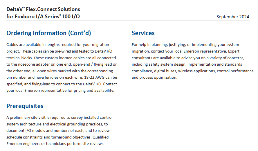
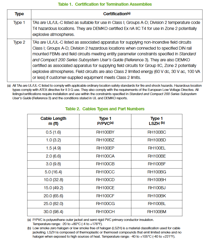
Cable requirements: Terminal cables support polyurethane or low smoke halogen-free (LSZH) materials, with a maximum length of 30m (98 feet); The module end is a 37 pin D-type miniature connector, and the TA end is a 25 pin D-type miniature connector. The specific model needs to refer to Table 2 (such as the 0.5m polyurethane cable model RH100BY).
Technical specifications
(1) Functional specifications
Category parameter details
HART device compatibility supports instruments that comply with HART version 5, 6, and 7 specifications
Communication method: point-to-point, master-slave, asynchronous, half duplex, baud rate of 1200
Analog output accuracy within 4-20mA range, ± 0.05% span (including linear error)
Output change rate can reach 20mA within 60 milliseconds
Resolution 13 bits
The maximum transmission distance complies with the HART FSK physical layer specification HCF_SPEC-54 (revised 8.1), with a maximum distance of 3030m (10000 feet). If an intrinsic safety barrier is used, the distance will be shortened
The power supply requires redundant 24V DC input, with a permissible voltage fluctuation range of+5%/-10%; Maximum power consumption 8W, maximum heat dissipation 4W
Calibration requirement module and terminal components do not require calibration
The anti pollution level meets the G3 level (harsh) environmental requirements of ISA standard S71.04 (based on EIA standard 364-65 level III exposure test) and meets the G3 level (harsh) environmental requirements of ISA standard S71.04 (based on EIA standard 364-65 level III exposure test)
Anti vibration performance within the frequency range of 5-500Hz, 7.5m/S ² (0.75g) within the frequency range of 5-500Hz, 7.5m/S ² (0.75g)
(3) Compliance certification
Electromagnetic compatibility (EMC): compliant with the EU EMC Directive (2004/108/EC, before April 20, 2016); 2014/30/EU, After April 20, 2016, it meets the EN61326-1:2013 Class A emission and industrial immunity level.
Environmental compliance: Compliant with the EU RoHS Directive 2011/65/EU.
Safety certification: UL/UL-C certification, suitable for hazardous environments with Class I A-D groups, Zone 2, T4 temperature codes (requires connection to designated Foxboro Evo processor modules); The communication circuit complies with the Class 2 circuit requirements of Article 725 of the National Electrical Code (NFPA 70) in the United States and Article 16 of the Electrical Code (CSA C22.1) in Canada; Compliant with the EU Low Voltage Directive (2006/95/EC, before April 20, 2016); 2014/35/EU, After April 20, 2016, DEMKO certified Ex nA IIC T4 according to the Explosion proof Directive (ATEX) and applicable to Zone 2 hazardous environments.
**Marine Certification * *: Obtained type approval from the American Bureau of Shipping (ABS) and ship certification from the Bureau Veritas, meeting the environmental category EC31.
Related documents and component information
(1) Reference Documents
Reference Number Document Number Document Description
Overview of PSS 31H-2COV Compact 200 Series I/O Subsystem
PSS 21S-8A3 B3 Intelligent Field Device Configurator FoxCom and HART Protocol
B0400FA Standard and Compact 200 Series Subsystem User Guide
5 PSS 2A-1Z3E PC20 Intelligent Field Device Configurator (applicable to FoxCom or HART protocol transmitters)
(2) Key component model
FBM218 module: RH101AE
Redundant adapter: RH101AY
Terminal Component (TA): RH926SP (replacing old models P0926SP, P0917XV), certified as Type 1 (UL/UL-C Class I A-D Group 2 T4, DEMKO Ex nA IIC T4 Zone 2)
Terminal cables: divided into two materials: polyurethane (P/PVC, -20 to+80 ° C) and LSZH (-40 to+105 ° C), with different lengths corresponding to different models. For example, the 0.5m polyurethane cable is RH100BY, and the 0.5m LSZH cable is RH100BC (see document table 2 for the complete model list).
FCN-RTU, as a remote monitoring unit of Yokogawa STARDOM series, integrates four core capabilities of “remote data acquisition, distributed control, multi protocol communication, and low-power operation and maintenance”, filling the gap of traditional RTUs in complex control and system compatibility. The specific functions cover:
Data acquisition: Supports analog (4-20mA, RTD/TC temperature), digital (24V DC switch signal), and pulse (flow counting, speed) acquisition, with a measurement accuracy of ± 0.1% FS, and supports channel level fault diagnosis (such as disconnection and short circuit detection);
Remote control: equipped with basic logic control (interlock protection, sequence control) and PID regulation functions, it can independently achieve localized control of remote stations (such as pump station pressure regulation, valve start stop), reducing dependence on the central system;
Narrow bandwidth adaptation: Supports narrow bandwidth communication such as GPRS/4G/LTE, satellite, microwave, etc. The data transmission adopts the “incremental upload+compression protocol” to reduce data consumption (such as compressing a single data upload to less than 1KB);
High reliability design: Key components (CPU, power supply, communication module) support redundant configuration, wide temperature range (-40~+70 ℃), anti-corrosion (G3 coating optional), anti vibration (5g/10-500Hz), suitable for unmanned harsh outdoor environments.
2. Typical Applicable Scenarios
Oil and gas industry: Station monitoring of long-distance oil and gas pipelines (such as oil pumps, valves, pressure transmitters), supporting interconnection with Yokogawa CENTUM VP DCS or SCADA systems to achieve leak detection and remote start stop;
In the field of new energy: monitoring of box transformers and combiner boxes in wind farms/photovoltaic power plants, uploading data on power generation, temperature, voltage, etc. through 4G/LTE, supporting on-site reactive power compensation control;
Water treatment and pipeline network: Pressure pump stations and flow meter monitoring for urban water supply pipelines, or remote aeration tank level regulation for sewage treatment plants, adapted to the low-power operation needs of remote sites;
Industrial distributed sites: cross plant equipment monitoring (such as tank farms in chemical plants and mineral processing equipment in mines), achieving centralized management of multiple sites through fiber optic or wireless bridging.
Key technical specifications and performance parameters
1. Hardware core specifications
Category core parameters (universal model, specific module slightly different)
Power module input: 12-48V DC (wide voltage adaptation, supports solar charging+battery backup); Output: 5V DC 3A (system power supply)+24V DC 2A (field device power supply), doubling the total output when configured redundantly
I/O module type analog input (AI): 4-20mA/1-5V (8-channel, isolated), RTD (platinum resistance, 8-channel), TC (thermocouple, 8-channel);
Analog output (AO): 4-20mA (4-channel, isolated);
Digital I/O (DI/DO): 24V DC 32 channel (DI)/16 channel (DO, relay output);
Pulse input: frequency 0-1kHz (4-channel, used for flow counting)
Expansion capability supports connecting remote I/O modules through RS-485 or dedicated expansion bus, with a maximum of 256 I/O points supported by a single RTU; Can cascade 8 expansion units, with a maximum transmission distance of 1km (twisted pair)/5km (fiber optic)
2. Communication and control performance
Communication interface:
Wireless communication: optional GPRS/4G/LTE modules (supporting dual card redundancy), satellite communication modules (such as Inmarsat BGAN);
Wired communication: 1 channel of 10/100Mbps Ethernet (supporting redundancy), 2 channels of RS-485 (Modbus RTU), 1 channel of RS-232 (debugging/local communication);
Protocol support: Modbus RTU/TCP, DNP3.0 (cascade/master), IEC 60870-5-101/104, MQTT (Internet of Things platform docking), supporting Yokogawa proprietary protocol (STARDOM Link).
Control performance: The control cycle is adjustable from 10ms-1s and supports 8 priority tasks; Built in PID control block (supporting automatic/manual switching, disturbance free switching), logic control block (such as AND/OR/NOT, delay), can achieve complex interlocking through programming.
3. Environmental and compliance characteristics
Environmental adaptability: working temperature -40~+70 ℃ (wide temperature), storage temperature -40~+85 ℃; Relative humidity of 5%~95% (non condensing, supporting condensing environment); Anti vibration level 5g (10-500Hz, IEC 60068-2-6), anti impact level 50g (1ms, IEC 60068-2-27);
Protection and certification: The enclosure protection level is IP40 (standard)/IP65 (outdoor type, optional), supporting G3 anti-corrosion coating (EN ISO 12944-5); Compliant with CE, UL 508, ATEX Zone 2 (Ex nA IIC T4), IECEx certification, suitable for hazardous areas and outdoor scenes.
System architecture and extension logic
1. Hardware architecture and redundancy design
FCN-RTU adopts a layered architecture of “main unit+expansion unit+remote I/O”, balancing flexibility and reliability:
Main unit: including CPU module, power module, basic I/O module and communication module, supporting DIN rail installation (size: 140 × 100 × 220mm, weight about 2.5kg), suitable for small control cabinets or outdoor cabinets;
Expansion Unit: Connected to the main unit via RS-485 or fiber optic cables, providing additional I/O interfaces (such as AI/AO/DI/DO modules). A single main unit can cascade up to 8 expansion units, suitable for centralized monitoring of multiple devices;
Redundant configuration: The CPU, power supply, and wireless communication module can be redundant with a redundancy switching time of less than 100ms. The communication link supports “wireless+wired” dual backup (such as 4G and fiber optic redundancy) to avoid disconnection caused by a single link failure.
2. Typical System Topology Example
plaintext
[Center SCADA/DCS] ←→ [Communication Network (4G/Satellite/Fiber Optic)] ←→ [FCN-RTU Main Unit (Redundant CPU+Power Supply)]
↓ (RS-485/fiber optic)
[Extension Unit 1 (AI/TC Module)] ←→ [Pipeline Pressure/Temperature Sensor]
↓
[Expansion Unit 2 (DI/DO Module)] ← → [Pump Station Motor/Valve actuator]
↓
[Expansion Unit 3 (Pulse Module)] ←→ [Flow Meter (Pulse Output)]
Engineering development and operation characteristics
1. Programming and configuration tools
FCN-RTU is equipped with Yokogawa STARDOM Engineering Tool kit, which complies with IEC 61131-3 standard and reduces the development threshold:
Control Designer: a control program development tool that supports FBD (Function Block Diagram), LD (Ladder Diagram), and ST (Structured Text) programming, and provides industry-specific function block libraries (such as oil and gas pipeline leak detection blocks and flow accumulation blocks);
System Configurator: a hardware configuration and communication parameter setting tool that visualizes the mapping of logical I/O and physical modules. It supports one click configuration of communication protocol parameters (such as DNP3.0) without the need to manually write drivers;
Offline Simulator: an offline simulation tool that can simulate on-site signals (such as pressure fluctuations and valve failures) on a PC, verify the correctness of control logic, and shorten on-site debugging time.
2. Operations and diagnostic capabilities
Low power operation and maintenance: supports “sleep wake” mode (such as sleep when there is no data, timed wake-up upload), and can achieve continuous 72 hour operation without sunlight in the scenario of solar+battery power supply;
Status monitoring and alarm: The main unit is equipped with an LCD display screen (128 × 64 pixels) and LED indicator lights, which display the real-time operating status (power, communication, I/O faults); Support local button operation (fixed value modification, log query), or export fault logs through USB interface;
Remote operation and maintenance: Remote diagnosis can be achieved through a web interface or Yokogawa PRM (Plant Resource Manager) system, supporting I/O channel calibration, firmware online upgrade, configuration file backup/recovery, and reducing on-site operation and maintenance frequency.
Key modules and selection information
1. Core module model and function
Module Type Model Example Core Functions
CPU module F3CU01 single CPU configuration, 1 Ethernet+2 RS-485, supports Modbus/DNP3 protocol
F3CU02 redundant CPU configuration, 2 Ethernet (redundant)+2 RS-485, suitable for high reliability scenarios
Power module F3PU01 12-48V DC input, single output (5V+24V), supports battery charging management
F3AR08 8-channel RTD input (platinum resistance 100 Ω), supporting wire breakage detection and cold end compensation
Communication module F3CM4G 4G/LTE wireless module, dual card redundancy, supports global frequency bands (1.8/2.1GHz)
F3CMSAT satellite communication module, compatible with Inmarsat BGAN network, supports communication in remote areas without base stations
Expansion module F3EX01 expansion bus interface module, realizing RS-485/fiber optic connection between the main unit and the expansion unit
2. Key dimensions for selection
I/O requirements: Determine the number of AI/AO/DI/DO points based on the type of on-site equipment (sensors/actuators), and select the number of basic I/O modules and expansion units for the main unit;
Communication environment: Satellite communication module is selected for areas without base stations, 4G/LTE module is selected for areas with mobile signals (dual card redundancy priority), and fiber optic+wireless backup is optional for fixed stations;
Environmental conditions: Choose IP65 protection and G3 coating for outdoor or harsh environments, support wide temperature range (-40 ℃) for low-temperature scenarios, and select ATEX certified models for hazardous areas;
Reliability requirements: Key stations (such as oil and gas pipelines) are equipped with CPU, power, and communication redundancy, while non key stations (such as ordinary pump stations) can be configured separately to reduce costs.
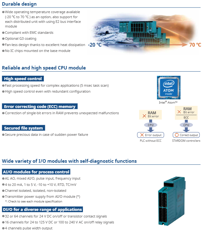
FCN-500 is a multifunctional autonomous controller launched by Yokogawa, integrating the four core capabilities of “control, measurement, communication, and diagnosis”. It aims to replace traditional PLCs and discrete control devices, and achieve centralized management of distributed processes. Its specific functions cover:
Process control: supports continuous control (PID regulation, ratio control), sequential control (logical interlocking, step control), and adapts to complex industrial processes (such as temperature control of chemical reaction vessels and pressure regulation of oil and gas pipelines);
Data acquisition and measurement: Real time acquisition of analog quantities (4-20mA, RTD/TC temperature signals), digital quantities (24V DC switch signals), and pulse quantities (frequency/pulse counting), with a measurement accuracy of ± 0.1% FS, meeting industrial grade metrology requirements;
Multi protocol communication: compatible with mainstream industrial buses such as FOUNDATION Fieldbus, HART, Modbus, PROFIBUS-DP, CANopen, etc., supporting interconnection with Yokogawa CENTUM VP DCS, ProSafe RS safety systems, and third-party SCADA (such as Schneider and Siemens systems);
High reliability design: Key components (CPU, power supply, communication bus) support redundant configuration, module hot plugging, wide temperature environment adaptation (-20~+70 ℃ optional), meeting the uninterrupted operation requirements of industrial sites.
2. Typical Applicable Scenarios
Petrochemical industry: used for reactor and distillation tower control in refining equipment, supporting linkage with HART intelligent valve positioner and Fieldbus analyzer to achieve precise adjustment of process parameters;
Energy industry: Suitable for monitoring of combiner boxes in wind and photovoltaic power plants, or logical control of auxiliary equipment (such as feedwater pumps and fans) in thermal power plants, supporting narrow bandwidth communication such as GPRS/satellite;
Water treatment and environmental protection: As the control unit for aeration tanks and sedimentation tanks in sewage treatment plants, it integrates flow calculation (AGA standard), liquid level regulation functions, and supports data exchange with online water quality monitoring instruments;
Distributed industrial scenario: suitable for cross regional pipeline network monitoring (such as natural gas long-distance pipelines), extending remote I/O through E2 bus to achieve centralized management of distributed units within 800 meters.
Key technical specifications and performance parameters
1. Hardware core specifications
Category core parameters (universal model, specific module slightly different)
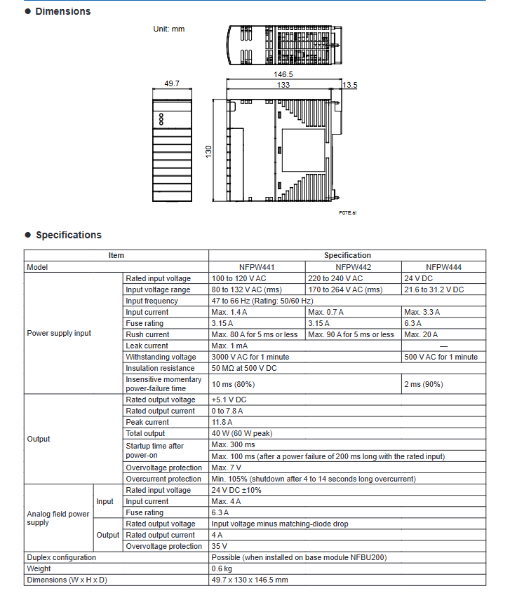
Power module input: 100-120V AC/220-240V AC/24V DC; Output: 5.1V DC 7.8A (system power supply)+24V DC 4A (field equipment power supply), supporting redundant configuration
I/O module type analog input (AI): 4-20mA, 1-5V, RTD (platinum resistance), TC (thermocouple), 8-16 channels, channel isolation/non isolation optional;
Analog output (AO): 4-20mA, -10~+10V, 4-16 channels;
Digital I/O (DI/DO): 24V DC 32-64 channels, relay output (24-125V DC/100-240V AC) 16 channels
Expansion capability supports E2 bus expansion of 8 remote I/O units, with a maximum transmission distance of 800 meters per line (fiber optic expansion can reach 5 kilometers); A single controller can support up to 79 I/O modules
2. Control and communication performance
Control cycle: minimum 5ms task scan, supports 16 priority tasks, meets fast response scenarios (such as motor start stop interlock);
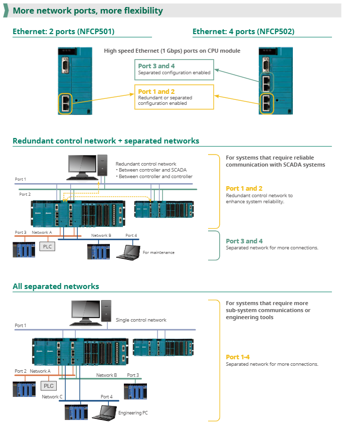
Communication interface: Standard configuration includes 2/4 1Gbps Ethernet (supporting redundant/independent network configuration), 1 RS-232/485 (Modbus RTU), and optional FOUNDATION Fieldbus/PROFIBUS-DP communication module;
Protocol support:
Upper computer: OPC DA 2.05a, DNP3, Modbus TCP;
Fieldbus: FOUNDATION Fieldbus (31.25 kbps), HART 7.0, PROFIBUS-DP (12Mbps);
Time synchronization: SNTP client/server ensures distributed unit time consistency.
3. Environmental and compliance characteristics
Environmental adaptability: Operating temperature range of 0-55 ℃ (standard)/-20~+70 ℃ (wide temperature range optional); Relative humidity ranging from 5% to 95% (without condensation); Anti vibration level 5g (10-500Hz, IEC 60068-2-6);
Protection and certification: The module shell has a protection level of IP20 (installed inside the cabinet) and supports G3 anti-corrosion coating (optional); Compliant with CE, UL 508, ATEX Zone 2 (some models) certification, suitable for hazardous areas.
System configuration and expansion logic
1. Hardware architecture and redundancy design
FCN-500 adopts a distributed architecture of “control unit+expansion unit”, with key components supporting redundant configuration to ensure high system availability:
Control unit: including CPU module, power module, basic I/O module, supporting 19 inch rack installation or DIN rail installation, providing three types of bases: long (NFBU200, up to 8 modules), short (NFBU050, up to 3 modules), and compact (N2BU030, 1 module), suitable for different installation spaces;
Expansion unit: Connected to the control unit through the E2 bus, each control unit can expand up to 8 expansion units, supporting mixed base configuration (long+short) to achieve flexible expansion of I/O points;
Redundant configuration: CPU, power supply, E2 bus, and Ethernet can all be redundant, with a redundancy switching time of less than 100ms to ensure seamless switching in case of faults.
2. Typical System Topology Example
plaintext
[Upper System] ← Ethernet (Modbus TCP) → [FCN-500 Control Unit (Redundant CPU+Power Supply)]
↓ (E2 bus)
[Extension Unit 1 (AI/AO module)] ←→ [On site sensors/actuators]
↓
[Expansion Unit 2 (DI/DO Module)] ←→ [Valve/Pump Control Circuit]
↓
[Expansion Unit 3 (Fieldbus Module)] ←→ [HART/Fieldbus Smart Devices]
Engineering development and operation characteristics
1. Programming and configuration tools
FCN-500 comes with Yokogawa Engineering Tool Kit, supporting IEC 61131-3 standard programming language to reduce development difficulty:
Logic Designer: a control program development tool that supports five languages: FBD (Function Block Diagram), LD (Ladder Diagram), ST (Structured Text), SFC (Sequential Function Diagram), and IL (Instruction List). It provides drag and drop programming and template libraries (such as PID control blocks and flow calculation blocks);
Resource Configurator: a hardware configuration tool that maps logical I/O to physical modules, supports IP address and communication protocol parameter settings, and does not require manual driver writing;
Simulator function: Supports hardware free debugging, can simulate control logic and I/O signals on a PC, and shorten the on-site debugging cycle.
2. Operations and diagnostic capabilities
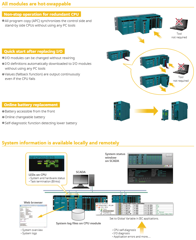
Module hot plugging: All I/O modules and power modules support online replacement, and the configuration is automatically loaded after replacement without the need for system shutdown;
Status monitoring: The CPU module comes with an LCD display screen and LED indicator lights, which display the system status (running/faulty) and I/O module health in real time; Support exporting logs (fault records, operation records) through SD card without the need to connect to a PC;
Remote operation and maintenance: Remote diagnosis can be achieved through Web HMI or Yokogawa PRM (Plant Resource Manager) system, supporting I/O channel fault location, module firmware online upgrade, and reducing on-site maintenance costs.
Key modules and selection information
1. Core module model and function
Module Type Model Example Core Functions
CPU module NFCP501 (2 Ethernet ports) with 2 Gigabit Ethernet channels, supporting Modbus/DNP3 protocols, with optional single/redundant configurations
NFCP502 (4 Ethernet ports) 4 Gigabit Ethernet channels, supporting independent network partitioning (such as control network+operation and maintenance network)
Power module NFPW441 (100-120V AC) system power supply (5.1V DC)+on-site power supply (24V DC), supports redundancy
NFPW444 (24V DC) DC input power supply, suitable for industrial 24V DC bus power supply scenarios
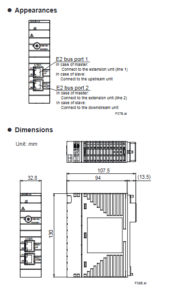
Expansion bus module N2EB100 E2 bus interface module, realizing the connection between control unit and expansion unit, supporting redundancy
2. Key dimensions for selection
Control scale: Select the base type (long/short/compact) and the number of expansion units based on the number of I/O points. A single system can support up to 79 I/O modules;
Environmental requirements: Standard temperature modules (0-55 ℃) are selected for conventional environments, wide temperature models (-20~+70 ℃) are selected for low/high temperature scenarios, and G3 coating is optional for corrosive environments;
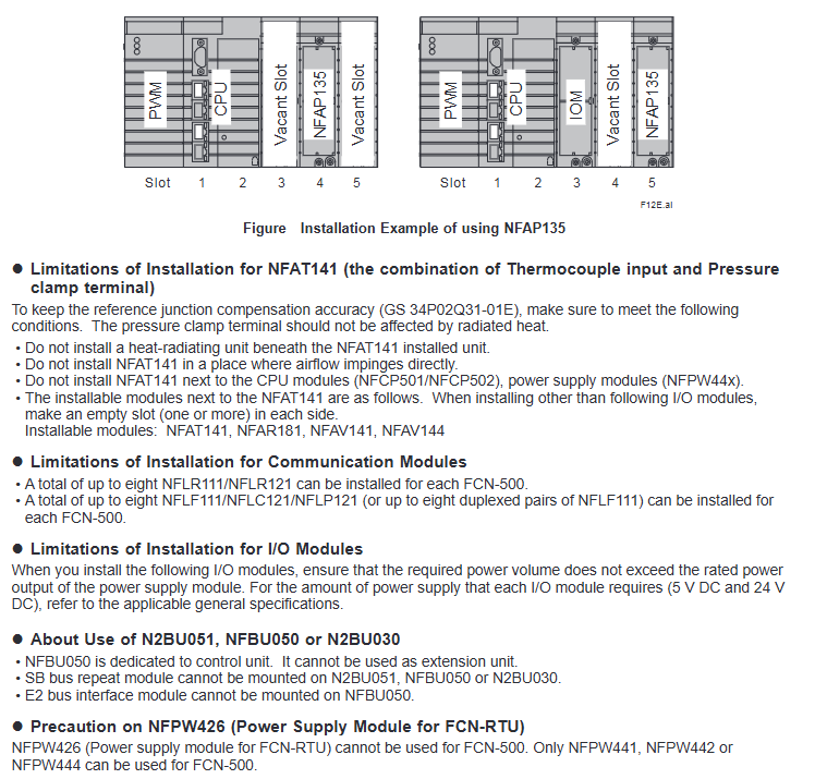
Communication protocol: Select the communication module based on the type of on-site equipment (such as selecting NFAI135 AI module for HART devices and NFLF111 module for Fieldbus devices);
Reliability requirements: For critical scenarios (such as chemical reaction control), CPU, power supply, and E2 bus redundancy should be configured. For non critical scenarios (such as regular monitoring), menu configuration is available.
This document is a technical document released by ABB for the REF54 series relay protection devices (presumably protection devices for medium and low voltage distribution systems, such as REF541, REF542, etc.). The core revolves around the functional characteristics, technical specifications, configuration logic, and application scenarios of the devices, aiming to guide electrical engineers in selecting devices, setting parameters, installing, debugging, and operating to ensure reliable protection of transformers, busbars, feeders, and other equipment in distribution networks (such as industrial plants, commercial buildings, and power distribution stations), in compliance with international relay protection standards such as IEC 60255.
Product core positioning and applicable scenarios
1. Core functional positioning
The REF54 series is a multifunctional digital relay protection device launched by ABB, integrating the four core functions of “protection, control, measurement, and communication”. It can replace traditional discrete protection relays and measurement instruments, achieve comprehensive monitoring and rapid response to faults of distribution equipment, and cover specific functions:
Protection function: Provides overcurrent protection (inverse time limit/definite time limit), overload protection, ground fault protection, short circuit protection, undervoltage/overvoltage protection, etc. for different protected objects (transformers, feeders, busbars), supports protection setting grading (adapted to different operating conditions).
Control function: Supports local/remote operation (such as circuit breaker opening and closing, constant value switching), has operation locking logic (to prevent misoperation), and can be connected to external control signals (such as PLC, SCADA system instructions).
Measurement function: Real time collection of electrical parameters, including three-phase current, voltage, power (active/reactive), power factor, and electrical energy (cumulative/instantaneous), with a measurement accuracy of 0.2 level (compliant with IEC 60688 standard).
Event recording: Automatically record fault events (fault type, occurrence time, fault time parameters), operation records (opening and closing operations, constant value modification), storage capacity supports ≥ 1000 events, facilitating fault traceability and operation and maintenance analysis.
2. Typical Applicable Scenarios
Industrial power distribution: used for the protection of factory workshop power distribution circuits and motor control circuits, adapted to high load, multi start stop industrial environments, and supporting linkage with ABB AC500 and other PLC systems;
Commercial and civil buildings: As feeder protection devices for office buildings and residential distribution stations, they achieve overload and short circuit protection for lighting, air conditioning, and other loads;
Power distribution network: used for low-voltage protection of transformers in 10kV/0.4kV distribution stations, in conjunction with ABB SCADA system to achieve remote monitoring and unmanned operation.
Key technical specifications and performance parameters
1. Electrical and protective characteristics
Category core specifications (general reference, specific models may vary slightly)
Input parameter current input: 5A/1A (standard CT secondary current); Voltage input: 100V/220V (PT secondary voltage, line voltage/phase voltage optional); Frequency: 50/60Hz (automatic recognition)
Protection range for overcurrent protection: 0.1-10Ie (Ie is the rated current); Overload protection: 0.5-1.5Ie; Ground fault protection: 0.05-5Ie; Action time limit: 0.01-300s
Trip outlet 2-4 sets of normally open/normally closed relay contacts (rated load: 5A@250VAC /30VDC), Support self checking of trip circuit (to avoid contact adhesion causing misoperation)
2. Communication and interface characteristics
Communication interface: Standard configuration includes 1 RS485 (supporting Modbus RTU protocol), optional 1 Ethernet (Ethernet/IP or Modbus TCP), supporting interconnection with upper computer (such as ABB MicroSCADA system), HMI or third-party control system to achieve data upload and remote control;
Local interface: Equipped with an LCD display screen (128 × 64 pixels, supporting Chinese/English display), 4 operation buttons (for setting settings and event queries), and some models come with a USB interface (for data export and firmware upgrade).
3. Environmental and compliance characteristics
Environmental adaptability: working temperature -25~+70 ℃ (wide temperature design), storage temperature -40~+85 ℃; Relative humidity ranging from 5% to 95% (without condensation); Anti vibration level 5g (10-500Hz, compliant with IEC 60068-2-6), suitable for complex environments inside distribution cabinets;
Compliance certification: Complies with IEC 60255 (General Standard for Relay Protection Devices), IEC 61000-6-2 (Electromagnetic Immunity for Industrial Environments), CE certification, UL 508 certification, and some models have passed ATEX Zone 2 explosion-proof certification (applicable to distribution in hazardous areas).
Configuration and operation points
1. Protection of fixed value configuration logic
The device supports configuring settings according to the “protection group” to meet different operating mode requirements (such as “normal operation”, “maintenance mode”, “backup power on/off”). The core configuration steps are as follows:
Enter the “Fixed Value Settings” menu (requires administrator privileges, password protection);
Select the type of protection object (such as “feeder protection” or “transformer protection”), and the system will automatically load the default protection logic template;
Adjust specific settings (such as overcurrent settings and action time limits), support real-time preview of the effective range of settings (to avoid exceeding the device’s allowable values);
Save the set value and activate it (some models require restarting the device or manually switching the protection group), and automatically record the set value modification event after activation.
2. Installation and wiring specifications
Installation method: Using standard DIN rail installation (35mm rail), compact size (width x height x depth about 90 x 140 x 180mm), suitable for installation inside 19 inch distribution cabinet doors or cabinets, with a reserved installation spacing of ≥ 50mm (for heat dissipation);
Wiring requirements:
Current circuit: Attention should be paid to the polarity of the CT secondary side wiring (“P1” in “P2” out) to avoid reverse connection and protection misoperation;
Voltage circuit: PT wiring needs to distinguish between line voltage (such as Uab, Ubc) and phase voltage (such as Ua, Ub, Uc) to ensure correct measurement and protection logic;
Communication circuit: RS485 uses shielded twisted pair cables (shielded layer single ended grounding), Ethernet uses CAT5e or above network cables, and the distance between strong current cables is ≥ 100mm to reduce interference.
Maintenance and troubleshooting
1. Regular maintenance plan
Daily inspection (daily/weekly): Check the LCD display screen to confirm that there are no fault alarms (such as “CT disconnection” or “PT voltage loss”); Check the status of the indicator lights (green power light on, flashing running light is normal);
Regular maintenance (monthly/quarterly): Clean the surface dust of the device (wipe with a dry dust-free cloth); Check the tightness of the wiring terminals (to avoid looseness and poor contact); Export event records and measurement data through the upper computer, analyze equipment operation trends;
Annual maintenance: Testing the accuracy of protection settings (using relay protection testers to simulate fault signals and verify the correctness of actions); Check the tripping outlet relay contacts (measure the continuity of the contacts with a multimeter); Upgrade device firmware (download the latest version from ABB’s official website and upgrade via USB or Ethernet).
2. Common faults and solutions
Possible causes and solutions for the fault phenomenon
The power light is not on, the power supply is not powered, the power module is faulty, and the wiring is loose. Check the output of the 220V/110V DC power supply; Re plug and unplug the power supply wiring; Replace the power module
The protection device refuses to operate and the protection setting is incorrect, the CT/PT wiring is reversed, and the tripping circuit fault occurs. Re check the protection setting (such as whether the overcurrent setting is lower than the fault current); Check CT/PT polarity; Test the tripping outlet relay (simulate the tripping signal with a tester)
Communication interruption (with upper computer), communication line failure, IP address conflict, protocol mismatch, replacement of communication line; Reconfigure RS485 address/IP address (to avoid conflicts); Confirm that the communication protocol is consistent (such as Modbus RTU slave address)
Display the “CT disconnection” alarm for CT circuit open circuit, CT fault, and internal sampling circuit fault. Check the CT secondary side wiring (whether it is open circuit); Measure the CT circuit resistance with a multimeter (normally ≤ 5 Ω); Contact ABB for after-sales inspection of the sampling circuit of the device