Call us 24/7uaedcs@163.com
Welcome to the official website of CNIACS Automation Technology Co., Ltd!
Call us 24/7uaedcs@163.com

Siemens 6ES7511-1AK02-0AB0 SIMATIC S7-1500 CPU 1511-1 PN

Product positioning and core identification

6ES7511-1AK02-0AB0 is a CPU 1511-1 PN central processing unit under the Siemens SIMATIC S7-1500 series, designed specifically for small and medium-sized industrial automation scenarios. Its core function is to integrate logic control, motion control, process control, and industrial communication capabilities, adapt to discrete manufacturing (such as machine tools and assembly lines), process industry (such as chemical and water treatment), and hybrid control scenarios, support distributed I/O expansion, and balance performance and flexibility.

Core hardware specifications

1. Processor and Storage

Category specific parameters

Typical processing speeds for bit operations are 60 ns, word operations are 72 ns, fixed-point arithmetic is 96 ns, and floating-point arithmetic is 384 ns, meeting the real-time control requirements of small and medium-sized systems

Working memory – Program memory: 150 KB (for storing user programs and system configurations)

-Data memory: 1 MB (cache process data, variables, and status information)

Loading memory supports 1 SIMATIC memory card (required, separately purchased), with a maximum capacity of 32 GB, used for program storage, data logging, and firmware upgrades

Keep Memory – Standard Keep Area: 128 KB (including timers, counters, flag bits, actually available 88 KB)

-Extended hold area: 1 MB (requires a 60W 24/48/60 V DC HF power supply)

2. Power supply and power consumption

Power supply voltage: 24 V DC (industrial standard DC power supply), allowable range 19.2~28.8 V DC;

Current parameters: rated current 0.7 A, maximum current 0.95 A, maximum impulse current 1.9 A (I ² t=0.02 A ² · s);

Power protection: supports reverse polarity protection to prevent equipment damage caused by wiring errors;

Power consumption: The input power of the backplane bus is 10 W, the balanced power consumption is 5.5 W, the typical power consumption is 5.7 W, and the low-power design is suitable for energy-saving systems.

3. Physical dimensions and installation

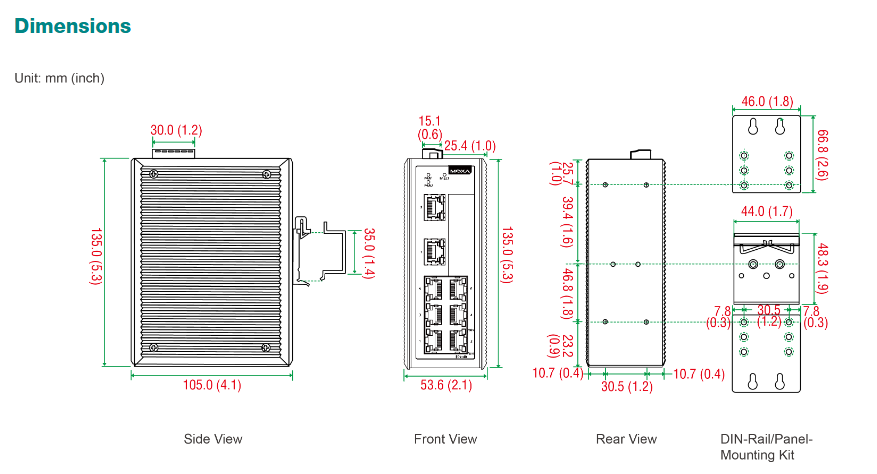
Dimensions: Width 35 mm x Height 147 mm x Depth 129 mm (Compact design, compatible with S7-1500 standard rack);

Installation method: DIN rail installation (compliant with EN 50022 standard), single rack supports up to 32 modules (CPU+31 expansion modules);

Weight: Approximately 405 g, lightweight design reduces the load-bearing pressure of the rack.

4. Display and operation

Display screen: A small 3.45 cm (1.36 inch) display panel used for status indication and basic operations;

Operation buttons: 8 function keys+2 mode buttons (RUN/STOP), supporting manual switching of operating modes and parameter settings;

Indicator lights: RUN/STOP, ERROR, MAINT, STOP ACTION, and LINK TX/RX status lights, providing visual feedback on device operation and communication status.

Communication interface and protocol

1. Core communication interface

Number and specifications of interface types

PROFINET interface 1 integrated PROFINET IRT interface (X1), including 2 RJ45 ports, built-in switch, supports 100 Mbps speed, with LINK TX/RX indicator light

Extended communication supports the expansion of interfaces such as PROFIBUS and Ethernet through CM/CP modules, and can accommodate up to 4 CM/CP modules

2. Support protocols and functions

(1) PROFINET Core Features

IO Controller/Device: Supports dual roles of PROFINET IO Controller and IO Device, connecting up to 128 IO Devices (of which 64 support IRT), and a total of 256 distributed I/O devices (including AS-i and PROFIBUS);

Real time performance: The minimum update time in IRT mode is 250 μ s (in conjunction with isochronous mode OB 6x, with a minimum cycle of 625 μ s), and the minimum update time in RT mode is 250 μ s;

Redundancy and Security: Supports Media Redundancy Protocol (MRP, compliant with IEC 62439-2), with a typical ring network switching time of 200ms; supports MRPD (requiring IRT), achieving interference free switching; Support PROFIenergy energy-saving protocol (requires user program configuration).

(2) Other industrial agreements

Industrial Ethernet protocols: TCP/IP, ISO on TCP (RFC1006), UDP (supports multicast, maximum data length 2 KB), DHCP, DNS, SNMP, DCP, LLDP;

SIMATIC proprietary protocols: S7 communication (client/server), S7 routing (up to 16 paths), PG/OP communication (supporting TLS V1.3 encryption);

Open protocol: OPC UA (requires “Small” operating license) MODBUS TCP;

Time synchronization: Supports NTP protocol and master-slave synchronization within AS, with a hardware clock backup time of 6 weeks (at 40 ℃ environment) and a maximum daily deviation of 10 seconds (typical 2 seconds).

3. Connection ability

Maximum number of connections: 96 (including integrated interfaces and extended CM/CP interfaces), with 10 reserved for ES/HMI/Web communication;

S7 Communication: Supports encrypted S7 communication, maximum user data length reference online help;

Web Server: Built in web server, supports HTTP/HTTPS access, customizable user pages, supports encrypted communication.

Control function and performance

1. Program and task management

(1) Program capacity and block resources

Specific parameters of resource type

Up to 4000 data blocks (DB) (including UDT), address range 1~60999 (user available 1~59999), maximum 1 MB per DB (absolute addressing DB maximum 64 KB)

Function blocks (FB/FC) have a maximum of 65535 FB and FC respectively, with a maximum of 150 KB for a single FB/FC/OB

Organizational Block (OB) supports multiple types of OB: 100 free loop OB, 20 time alarm OB, 20 loop interrupt OB (minimum cycle 500 μ s), 50 process alarm OB, etc

(2) Task scheduling

Support priority task management (levels 0-15), with each priority class nested at a depth of 24 levels;

The isochronous mode supports both distributed and centralized modes, with a minimum OB 6x cycle of 625 μ s (distributed) and 1 ms (centralized), meeting high-precision synchronous control requirements.

2. Timers and counters

S7 timer/counter: 2048 each, supporting retention (configurable);

IEC timer/counter: unlimited quantity (limited only by memory), supports persistent configuration;

Clock memory: 8 clock memory bits (1 byte) used to generate periodic signals (such as 0.5 s, 1 s pulses).

3. Technical functions (motion, process control)

(1) Motion control

Resource support: Supports Motion Control technology objects, with a total of 800 resources allocated as follows:

Speed control axis: 40 resources/axis; Positioning axis: 80 resources/axis; Synchronization axis: 160 resources/axis;

External encoder: 80 resources per unit; Output cam: 20 resources/piece; Cam trajectory: 160 resources/piece; Probe: 40 resources/piece;

Number of axes: up to 5 positioning axes in a 4 ms motion control cycle, and up to 10 positioning axes in an 8 ms cycle.

(2) Process control

PID controller: supports PID_Compact (universal PID), PID_Step (valve specific), PID Test (temperature specific), all with integrated optimization function;

High speed counting: Supports high-speed counter function and is suitable for pulse signal acquisition (such as encoder signals).

4. Diagnosis and Debugging

Diagnostic buffer: up to 1000 records (including 500 power down hold), recording device faults, program errors, and other information;

Tracking function: up to 4 configurable traces, each with a maximum of 512 KB of data, used to record variable changes and program execution trajectories;

Online debugging: Supports Team Engineering (up to 5 engineering systems can be accessed online in parallel), up to 8 breakpoints, variable status monitoring and forcing (up to 200 peripheral I/O variables).

Environmental adaptability and certification

1. Environmental parameters

Specific indicators of environmental parameters

Working temperature – horizontal installation: -25 ℃~60 ℃ (the display screen automatically turns off when it reaches 50 ℃)

-Vertical installation: -25 ℃~40 ℃ (display screen automatically shuts off at 40 ℃)

Storage/transportation temperature -40 ℃~70 ℃ (non condensing)

Relative humidity 5%~95% RH (non condensing)

The maximum installation altitude is 5000 meters (when the altitude is>2000 meters, please refer to the manual for restrictions)

The anti vibration performance meets the IEC 60068-2-6 standard, with a maximum acceleration of 5 m/s ² at frequencies ranging from 10 to 500 Hz

The impact resistance performance meets the IEC 60068-2-27 standard, with a continuous duration of 11 ms at an acceleration of 15 g

2. Compliance certification

Safety certification: UL 508, CSA C22.2 No. 142, EN 61131-2;

Electromagnetic compatibility (EMC): EN 61000-6-2 (anti-interference in industrial environments), EN 61000-6-4 (emission in industrial environments);

Hazardous environment certification: Supports EX Zone 2/22 (requires corresponding module coordination);

Regional compliance: CE mark, in compliance with EU market access requirements.

Programming and Security

1. Programming software and language

Supported software: STEP 7 TIA Portal V15 (firmware V2.5) and above, V17 supports firmware V2.9; The old version of TIA Portal is compatible with configuration 6ES7511-1AK01-0AB0;

Programming language: Supports ladder diagrams (LAD), function block diagrams (FBD), statement tables (STL), structured text (SCL), and sequential function diagrams (GRAPH) to meet different programming habits.

2. Security protection

Program protection: supports user password protection, block protection, and copy protection (Know how protection) to prevent unauthorized modification and copying;

Data Security: Confidential configuration data protection, display password protection, support three-level access permissions (write protection, read/write protection, full protection);

Communication encryption: PG/OP communication, web servers, S7 communication support TLS V1.3 encryption, OPC UA supports multiple security policies (such as Basic256Sha256).

Allen Bradley 1769-L32E (CompactLogix L32E)

Product positioning and core identification

1769-L32E is a compact programmable automation controller (PAC) from the Allen Bradley CompactLogix L32E series, designed specifically for small and medium-sized industrial automation scenarios. Its core function is to integrate logic control, motion control, and process control capabilities to achieve centralized management of discrete devices (such as machine tools, assembly lines) or small production lines. It is also compatible with Allen Bradley 1769 series I/O modules, balancing flexibility and cost-effectiveness.

Core hardware specifications

1. Processor and Storage

Category specific parameters

Processor performance: 32-bit processor, supports parallel task processing, with a logic control instruction execution speed of 0.68 ms/k ladder diagram instructions, meeting the real-time requirements of small and medium-sized systems

Memory Configuration – Program Memory: 512 KB (used to store user programs and system configurations)

-Data memory: 1 MB (used for caching process data, variables, and status information)

Storage expansion supports external microSD card expansion (available separately) for program backup, data log storage, or firmware upgrade, enhancing data storage flexibility

2. Physical dimensions and installation

Dimensions: Width 44.5 mm x Height 118 mm x Depth 86 mm (Compact design, compatible with 1769 series standard rack);

Installation method: Supports DIN rail installation (compliant with EN 50022 standard) or panel installation, and needs to be paired with 1769 series racks (such as 1769-A10, 1769-A13, etc.). A single rack can expand up to 16 I/O modules;

Weight: Approximately 0.3 kg, lightweight design reduces the load-bearing pressure of the rack.

3. Power supply and power consumption

Power supply voltage: 24 V DC (industrial standard DC power supply, compatible with control cabinet centralized power supply);

Rated current: 0.5 A (without expansion module), after expanding the I/O module, the power supply capacity needs to be increased according to the total power consumption;

Power protection: Supports overcurrent protection and reverse polarity protection to prevent equipment damage caused by abnormal power supply;

Power consumption: Typical power consumption of 12 W (without expansion), low-power design, suitable for energy-saving automation systems.

Communication interface and protocol compatibility

1. Built in communication interface

Number and specifications of interface types

Ethernet interface with 1 RJ45 port, supporting 10/100 Mbps adaptive speed, with Link/Activity indicator light, used to connect to upper computer, HMI or other controllers

Internal backplane interface: 1 1769 series backplane interface, supporting high-speed communication with I/O modules of the same series (such as digital, analog, and special modules), with a backplane data transmission rate of 16 Mbps

One USB 2.0 port (Type B) is used to connect to a programming computer, enabling program download, upload, and online monitoring, simplifying the debugging process

2. Support communication protocols

Industrial Ethernet protocols: EtherNet/IP (core protocol, supports CIP communication, enables data exchange between controllers and real-time I/O control), Modbus/TCP (compatible with third-party devices such as instruments and frequency converters);

Internal communication protocols: CIP Motion (for motion control, supporting single axis or multi axis synchronous control), CIP Sync (IEEE 1588 precise time synchronization, improving multi device collaboration accuracy);

Programming and Configuration Protocol: RSLinx Communication Driver (adapted to Rockwell RSLinx Classic/Enterprise software to achieve device discovery and data collection).

3. Controller compatibility

Compatible with I/O modules: Supports all 1769 series I/O modules, including digital input/output (such as 1769-IQ16, 1769-OB16), analog input/output (such as 1769-IF4, 1769-OF4), high-speed counter (such as 1769-HSC), temperature acquisition (such as 1769-IT6), etc;

Compatible with upper computer/terminal: Can connect Allen Bradley PanelView series HMI (such as 2711P series) and Rockwell FactoryTalk monitoring software to achieve visual operation and remote management.

Core functions and performance

1. Control ability

(1) Logic control

Programming language support: compatible with Rockwell Studio 5000 programming software, supporting four standard programming languages: ladder diagram (LD), function block diagram (FBD), structured text (ST), and sequential function diagram (SFC), to meet the programming habits of different engineers;

Task management: Supports up to 32 user tasks (including periodic tasks and event triggered tasks), with configurable task priorities (levels 0-15) to ensure priority execution of critical control tasks;

Instruction set: Built in rich instruction library, including basic logic instructions (such as contacts, coils), mathematical operation instructions (such as addition, subtraction, multiplication, division, trigonometric functions), data processing instructions (such as shift, comparison), string instructions, covering the control requirements of small and medium-sized systems.

(2) Motion control (optional extension)

Support the extension of motion control functions through the CIP Motion protocol, which can be connected to motion control modules such as 1769-M02AS to achieve single axis positioning, speed control, or multi axis synchronization (such as electronic gears, electronic camshafts);

Supports up to 8-axis motion control (requires corresponding module expansion), suitable for small machine tools, packaging machines, and other equipment that require precise motion control.

(3) Data Processing and Logging

Data recording: Supports storing process data (such as production counts and equipment operating status) in. csv format through microSD card or Ethernet, facilitating later data analysis and report generation;

Fault diagnosis: Built in fault self diagnosis function, can monitor the hardware status of the controller, communication link faults, program errors, and display alarm information through indicator lights or upper computer to quickly locate the problem.

2. Safety and reliability

Program security: supports user permission management (such as programmers, operators, read-only users), can set password protection programs to prevent unauthorized modifications;

Environmental adaptability:

Working temperature: 0 ℃~60 ℃ (covering the normal temperature environment of industrial workshops to avoid extreme high temperatures);

Storage temperature: -40 ℃~85 ℃ (to meet the needs of logistics transportation and warehouse storage);

Relative humidity: 5%~95% RH (non condensing, to avoid circuit faults caused by moisture);

Anti vibration performance: compliant with IEC 60068-2-6 standard, maximum acceleration of 2g at frequencies of 10-500 Hz, suitable for workshop equipment vibration environment;

Impact resistance: Compliant with IEC 60068-2-27 standard, capable of withstanding installation or transportation impacts for 11 ms at an acceleration of 15 g.

International certification

Safety certifications: UL 508 (Industrial Control Equipment Safety Standard), CSA C22.2 No. 142 (Canadian Safety Standard), IEC 61131-2 (Programmable Logic Controller Safety Standard);

Electromagnetic compatibility (EMC) certification: EN 61000-6-2 (industrial environment anti-interference standard), EN 61000-6-4 (industrial environment emission standard), FCC Part 15 Class A (American electromagnetic compatibility standard);

Regional compliance: Meets CE marking requirements and can be sold and used in the European Union and regions that recognize CE standards.

Allen-Bradley 2711P-RDT7C PanelView ™  Plus 6 700

Product positioning and core identification

2711P-RDT7C is a PanelView from Rockwell Automation (Allen Bradley) ™  The 700 model industrial human-machine interface (HMI) display module under the Plus 6 series is designed specifically for industrial automation scenarios. Its core function is to achieve visual interaction between operators and automation systems (such as PLC, frequency converter), support equipment monitoring, parameter setting, data recording and other operations, and is widely applicable to small and medium-sized equipment in discrete manufacturing (such as machine tools, assembly lines), process control (such as chemical engineering, water treatment) and other fields.

Core hardware specifications

1. Display and operation unit

Category specific parameters

Display screen 6.5-inch TFT color screen, resolution 640 × 480 pixels, brightness 300 cd/m ², clear color display, suitable for workshop strong light environment

Backlight system cold cathode fluorescent lamp (CCFL) with an average lifespan of 50000 hours, meeting the long-term continuous industrial operation requirements

Touch function resistive touch screen, supporting precise single point touch operation, resistant to oil stains and wear, suitable for frequent use in industrial sites

The operation mode only involves touch input (without physical buttons), and the interface design is simple, reducing the risk of mechanical failure

2. Physical dimensions and installation

Hole size: width 220 mm x height 154 mm (standard hole for control cabinet, convenient for integrated installation);

Product dimensions: width 246 mm x height 179 mm x depth 55 mm, compact size, saving internal space of the control cabinet;

Weight: 1.7 kg, lightweight design, reduces installation load requirements;

Protection level: IP65 on the front (dustproof, splash proof, can be directly exposed to damp/dusty environments in the workshop), and the back needs to be installed inside the control cabinet (no clear protection level label, default to avoid direct contact with pollutants).

3. Environmental adaptability

Specific indicators of environmental parameters

Working temperature: 0 ℃~55 ℃ (covering most industrial workshops at room temperature to avoid extreme high/low temperatures)

Storage temperature -25 ℃~70 ℃ (meets the temperature and humidity requirements for logistics transportation and warehouse storage)

Relative humidity 5%~95% RH (non condensing, to avoid circuit short circuits or component aging caused by humidity)

Maximum acceleration of 15 g, duration of 11 ms, in compliance with IEC 60068-2-27 standard, resistant to transportation/installation impact

Anti vibration performance: maximum acceleration of 2 m/s ², peak displacement of 0.012 mm, maximum operating frequency of 500 Hz, in compliance with IEC 60068-2-6 standard, suitable for workshop equipment vibration environment

Ship certification is not available (not applicable to ship automation scenarios)

Performance and functional characteristics

1. Core performance parameters

Processor and Storage: Equipped with a high-performance processor and 512 MB of memory, it has fast response speed and supports complex interface rendering and multitasking;

Operating System: Pre installed Windows CE 6.0 system, high stability, compatible with industrial grade applications, supports third-party software integration;

Multi language support: Built in full Unicode fonts, a single runtime application can support multiple language switching (such as Chinese, English, German), suitable for cross-border factories or multilingual operation scenarios.

2. Key functions

(1) Data Management and Document Support

Formula management: supports the creation, storage, and retrieval of equipment process formulas, suitable for the production of multi specification products (such as switching processing parameters for parts of different sizes);

Data tracking: Record process data (such as production counts and equipment operating hours) in. csv format files for subsequent analysis and report generation;

PDF viewing: Equipped with a built-in PDF reader, it can load equipment manuals, operation guides, and other documents, providing context sensitive operator support (such as quick access to troubleshooting steps in case of malfunctions).

(2) Network and Communication

Built in interface:

Serial communication: 1 RS-232 port, compatible with traditional industrial equipment such as old PLCs and instruments;

Ethernet: 1 Ethernet port, supporting industrial Ethernet communication, enabling high-speed data exchange with the controller;

Expansion interface: Built in USB port (for external device connection, such as mouse and USB data transfer) and SD card slot (for extended storage, saving recipes or log files);

Remote monitoring: supports real-time monitoring of terminal status (such as device operation data and alarm information) through a web browser, without the need for on-site operation, improving operation and maintenance efficiency.

(3) Modular design

Adopting a modular architecture of “logic module+display module+communication module”, it can expand functions as needed (such as adding communication protocol support, upgrading logical computing capabilities), reduce later transformation costs, and facilitate fault diagnosis and module replacement.

Compliance certification and reference documents

1. Certification standards

Basic certification: Complies with the IEC series standards (impact resistance IEC 60068-2-27, vibration resistance IEC 60068-2-6) to ensure reliability in industrial environments;

Explosion proof/Special Certification: No hazardous environment certification such as IECEx (not applicable to explosion-proof areas such as chemical, oil and gas);

Regional Compliance: Provide a Supplier Declaration of Conformity to meet market access requirements in different regions.

2. Reference materials

Users can obtain the following documents through Allen Bradley’s official channels, which support installation and operation:

Installation Guide: Detailed instructions on equipment drilling, wiring, and fixing steps;

User Manual: covering interface configuration, function configuration, troubleshooting, and other operations;

Manufacturer’s data manual and product selection catalog: Provide complete technical parameters for comparison with products in the same series to assist in selection.

Siemens 6AV6642-0DA01-1AX1 SIMATIC OP177B (HMI)

Product positioning and core identification

6AV6642-0DA01-1AX1 is the OP177B industrial human-machine interface (HMI) under the Siemens SIMATIC series, designed specifically for industrial automation scenarios. Its core function is to enable visual interaction between operators and controllers (such as PLCs), supporting parameter settings, process monitoring, alarm recording, and other operations. It is compatible with various fields of equipment such as discrete manufacturing and process control (such as machine tools, production lines, control cabinets).

Core hardware specifications

1. Display and operation unit

Category specific parameters

Display screen 5.7-inch STN color screen, resolution 320 × 240 pixels, supports 256 color display; Screen size 120mm × 90mm

The average time between failures (MTBF) of the backlight in a 25 ℃ environment is about 50000 hours, meeting the long-term industrial operation requirements

Dual operation mode: thin film keyboard+analog resistive touch screen, balancing precise input and fast operation

32 programmable function keys (including 26 keys with LED status indicators) are configured for key configuration, supporting numeric/alphabetical/hexadecimal input and multiple key simultaneous operation

Expand input with one USB interface, which can be connected to a mouse, keyboard, or barcode reader to enhance data input flexibility

2. Processor and Storage

Processor: ARM architecture, with a main frequency of 200 MHz, ensuring interface response and data processing speed;

Storage type: Flash flash+RAM memory, available storage space for user data is 2048 KB;

Clock module: hardware clock, supports synchronization function, but does not have battery backup (time needs to be recalibrated after power failure);

Extended storage: Supports MMC/SD card expansion (requires E version 016 and above, and comes with WinCC flexible 2008 SP1 software).

3. Power supply and power consumption

Power supply voltage: 24 V DC (industrial standard DC power supply, compatible with control cabinet power supply);

Rated current: 0.24 A;

Impulse current: 0.5 A ² · s (to avoid impact on the power system when powered on).

4. Protection level and installation

Protection performance: Positive protection level IP65, NEMA 4x/12 (dustproof and splash proof after installation, suitable for humid/dusty environments such as workshops); Back protection level IP20 (to be installed inside the control cabinet to avoid direct exposure);

Installation method: Vertical installation, maximum allowable tilt angle ± 35 ° (without external ventilation conditions);

Physical dimensions: Front dimensions 243 mm × 212 mm, weight approximately 1 kg, suitable for standard control cabinet opening installation.

image.png

Communication interface and protocol

1. Interface configuration

Number and specifications of interface types

Industrial Ethernet 1 RJ45 interface, maximum transmission rate of 12 Mbit/s, supports industrial grade network communication, with status indicator light

RS485/RS422 1 RS485 interface+1 RS422 interface, supports serial communication, compatible with traditional industrial equipment (such as frequency converters, instruments)

RS232 optional, expand serial communication capability as needed

USB 1 USB interface, used for external device connection or data transfer

The printer interface supports printer connection and can print documents such as alarm records and shift handover reports

2. Support protocol and controller compatibility

Core protocols: MPI (Multipoint Interface), PROFIBUS-DP (Industrial Fieldbus), PROFINET (Industrial Ethernet) Sm@rtServer agreement;

Compatible controller:

Siemens series: S5, S7-200, S7-300/400, Win AC, SINUMERIK (numerical control system), SIMOTION (motion controller);

Third party brands: Allen Bradley (DF1 protocol), Mitsubishi (FX series), Telemecanique (ADJUST/Uni Always protocol), Modicon (Modbus protocol), etc., compatible with multi vendor automation systems;

Communication function: Supports configuration file upload/download (via MPI/PROFIBUS DP, serial, etc.) USB、 Ethernet or external storage media), supporting automatic transmission recognition.

Software configuration and functionality

1. Software configuration requirements

Siemens specialized HMI configuration software is required, supporting the following versions:

Basic configuration: WinCC flexible Compact 2005 and above versions (need to be ordered separately) WinCC flexible Standard/Advanced;

TIA Portal compatibility: Supports WinCC Comfort/Advanced/Professional (TIA Portal environment), does not support STEP 7 Basic/Professional or WinCC Basic;

Core tool: Implement interface design, variable association, alarm configuration and other functions through WinCC flexible software, supporting project template and library file reuse.

2. Core functions and performance

(1) Monitoring and Display

Screen configuration: Supports up to 500 configurable screens, supports permanent/default windows, customizable startup screen, supports screen switching through PLC control, and screen numbers can be displayed on the screen;

Object elements: Each project supports up to 500 objects, each screen supports 5 dynamic objects (such as trend chart, bar chart, slider, analog display, hidden button), supports 2500 text elements, 30 date/time fields, 500 icons (including 50 full screen icons);

Variable management: A single device supports 1000 variables, each screen supports 50 variables, supports initial and limit value settings, supports variable multiplexing, but does not support structural variables;

Process value display: Supports displaying process values in numerical, textual, and graphical formats (such as bar charts and trend charts), with a maximum of 5 data bars per trend chart and support for displaying limit lines.

(2) Alarm and Log

Alarm management: supports 2000 bit messages and 50 analog messages, up to 32 alarm categories, and supports 99 confirmation groups;

Log function: with alarm buffer and confirmation mechanism, supporting alarm log printing (including color printing and hard copy), supporting shift report generation (handover report);

Message configuration: Each message has a maximum length of 80 characters, supports displaying 8 process values in association, and supports system messages (HMI self status) and PLC messages (controller fault/status).

(3) Formula management

Formula capacity: Supports up to 100 formulas, with each formula containing 200 data records and each data record containing 200 entries;

Storage Expansion: Basic recipe storage of 32 KB (integrated with Flash), expandable storage capacity through MMC/SD card, suitable for multi product production scenarios (such as quick switching of process parameters for different specifications of products).

(4) Security and Permissions

User management: supports 50 user groups, 32 user permission levels, and can assign operational permissions according to roles (such as operators can only monitor, administrators can modify parameters);

Password function: Supports password import/export, records up to 1000 password error attempts, and enhances system security.

Environmental adaptability and certification

1. Environmental parameters

Working temperature: not clearly indicated, refer to storage/transportation temperature (-20 ℃~+60 ℃), suitable for most industrial workshop environments (extreme high/low temperatures should be avoided);

Relative humidity: maximum 90% (non condensing, to avoid circuit faults caused by moisture);

Transportation/storage temperature: -20 ℃~+60 ℃, meeting the needs of logistics transportation and warehouse storage.

2. Compliance certification

This product has passed multiple international industrial certifications and is suitable for applications in multiple regions around the world

Safety certification: CE, UL, CSA, cULus;

Hazardous environment certification: FM Class I Div. 2, EX Zone 2/22 (can be used in non explosion proof areas such as chemical, oil and gas hazardous areas);

Classification certification: GL, ABS, BV, DNV, LRS (some models support, can be used for ship automation systems);

Electromagnetic compatibility: Complies with industrial EMC standards, has strong anti-interference ability, and is suitable for complex electromagnetic environments (such as workshops with dense motors).

Emerson PACSystems RX3i I/O Module

Product positioning and core values

PACSystems RX3i I/O is a modular industrial grade input/output system launched by Emerson, designed specifically for process control, hybrid control, and discrete control scenarios. Its core advantages lie in high-performance data transmission, flexible scalability, and comprehensive diagnostic capabilities, which can adapt to automation needs from small and medium-sized equipment to large and complex production lines. At the same time, it provides a convenient legacy system upgrade path to protect users’ existing investments.

Core Features and Advantages

1. Modular design and high-speed performance

Rich module types: covering digital quantities (voltage, relay output), analog quantities (voltage/current, RTD, thermocouple), and special I/O (high-speed counter, PWM pulse output, strain gauge acquisition, event sequence SoE input), supporting different voltage ranges (such as 24Vdc, 120Vac) and current capacities to meet diverse industrial signal processing needs;

Hot swappable function: All I/O modules support hot swappable, allowing for module replacement without the need to power off, reducing maintenance downtime;

High speed data transmission: Based on high-speed backplane interface, it ensures fast and stable transmission of I/O data, with response speed far exceeding traditional control systems, and is suitable for scenarios with high real-time requirements (such as motion control and precision process adjustment).

2. High scalability and flexible deployment

Customizable scale: A single system supports 8-32000 I/O points, providing various specifications of backplanes such as 7-slot, 12 slot, 16 slot, and 1-slot expansion units, which can be flexibly combined according to application scale;

Multi scenario expansion: Supports local expansion (main backplane overlay expansion backplane) and remote expansion (connected to remote I/O racks through Ethernet or serial bus), with a maximum of 448 I/O points supported by a single drop, suitable for decentralized device layout (such as multi area control in large factory areas);

Media compatibility: support copper cable, SM Fiber, and MM Fiber, and adapt to different transmission distance requirements (such as long-distance communication across buildings in the plant).

3. High availability and redundancy guarantee

Multi level redundancy:

Network redundancy: Supports Media Redundancy Protocol (MRP) and dual LAN architecture to avoid single network link failures;

System redundancy: compatible with PROFINET system redundancy (PNSR) and Ethernet global data (EGD), achieving bumpless switching over between controllers and I/O systems;

I/O redundancy: Key I/O channel redundancy can be configured through application code to further enhance system reliability;

Anti interference and environmental adaptability: Equipped with * * galvanic isolation * * (supporting both digital and analog input and output), strong anti electromagnetic interference capability; The default working temperature is 0-60 ℃, with optional -40~60 ℃ wide temperature version and normal coating (moisture-proof, dust-proof), suitable for harsh industrial environments.

4. Convenient maintenance and compatibility

Easy to connect design: All modules are equipped with pluggable terminal blocks, supporting solid/multi strand wires of 0.081~1.5mm ² (28~14AWG), providing both spring and box terminal types, supporting Terminal Block Quick Connect (TBQC) and forward fixation to ensure stable wiring;

Legacy system upgrade friendly: Series 90-30 modules can be directly reused on the RX3i backplane without rewiring or replacing I/O devices, and the upgrade process only takes a few hours (instead of the traditional solution of days); Simultaneously integrating Ethernet and USB interfaces to replace outdated serial interfaces, enhancing communication flexibility and speed (over 100 times faster than legacy systems).

Detailed explanation of technical specifications

1. Hardware and environmental parameters

Category specific parameters

Installation methods: Panel Mount, Rack Mount

Protection level IP20 (dustproof, preventing fingers from entering)

Working temperature standard: 0-60 ℃; Optional wide temperature range: -40~60 ℃

Isolation performance: All DI/DO/AI/AO channels support galvanic isolation to reduce ground current interference

Terminal specifications: Low density terminals support up to 12AWG wires, while high-density terminals support up to 14AWG wires

Certification standards UL, UL Hazardous Area Certification (Class I Division 2), CE, ATEX Zone 2; Some models support classification certification (ABS, BV, DNV GL)

2. Network and communication capabilities

Core network interfaces: PROFINET, Modbus/TCP, Ethernet Global Data (EGD), Control Memory Switching (CMX), PROFIBUS DP;

Gateway/Bridge Function: Supports serial communication Modbus/RTU、HART、GENIUS、DNP3 Serial/TCP、IEC-61850、IEC-104、 Reflective Memory, CANOpen, etc. can seamlessly integrate with devices from different manufacturers, such as instruments, frequency converters, and third-party PLCs;

Communication port: equipped with 2 RJ45 Ethernet ports and 2 SFP optical ports, supporting flexible switching between fiber and copper cables.

3. Diagnostic and monitoring capabilities

Advanced diagnostic function: The module is equipped with a comprehensive self diagnostic mechanism, which can monitor the terminal wiring status, signal abnormalities (such as overcurrent and over range), module faults in real time, and display alarm information through the controller or upper computer (such as Emerson Proficy software) to quickly locate the problem;

Status visualization: The module LED indicator lights provide clear feedback on power, communication, and channel fault status, making it easy for on-site maintenance personnel to quickly troubleshoot.

I/O module classification and typical models

1. Digital I/O module

Module type, typical model, key parameters

Digital input IC694MDL645 24Vdc, 16 points, positive and negative logic, isolated

IC694MDL240 120Vac, 16:00, non isolated

Digital output IC694MDL730 12/24VDC, 2A, 8 points, positive logic

IC694MDL930 relay output (normally open), 4A, 8 points, isolated

Mixed digital I/O IC694MDR390 24Vdc input (8 points)+relay output (8 points), integrated input-output function

2. Analog I/O module

Module type, typical model, key parameters

Analog input IC695ALG600 universal type, supports voltage/current/RTD/thermocouple, 8-channel non isolated/4-channel differential

IC695ALG306 isolated thermocouple input, 6-channel, compatible with various thermocouple types such as J/K/T

Analog output IC694ALG392 8-channel, supports voltage/current output, non isolated

IC695ALG728 8-channel, voltage/current output, supports HART protocol, can communicate with smart instruments

Mixed analog I/O IC694ALG442 with 4 analog inputs and 2 analog outputs, supporting voltage/current signals

3. Special and Interface Modules

Module type, typical model, key parameters

High speed counter IC695HSC304 1.5MHz, 8 inputs, 7 outputs, supports quadrature encoding, pulse counting, etc

IC694DSM324 multi axis motion controller, compatible with servo/stepper motor control, supports point and trajectory planning

Communication module IC695PNC001 PROFINET controller module, realizing PROFINET network management and device docking

IC695CMM004 4-port serial communication module, supporting RS232/485, compatible with Modbus/RTU and other protocols

Power module IC695PSA040 120/240VAC input, 125Vdc output, 40W, providing stable power supply for the main backplane

IC695PSD140 24Vdc input, 40W multi-purpose power supply, suitable for DC power supply scenarios

Comparison with other Emerson I/O products

The positioning differences between RX3i I/O and other Emerson I/O series can be clearly distinguished through the following table for easy selection:

Product Series Types Core Features Typical Application Scenarios Environmental Adaptability

PACSystems RX3i Chassis Based high performance, high diagnostic capability, support for redundant complex machine control, process control, motion control 0~60 ℃ (optional -40 ℃ wide temperature)

RSTi EP distributed slice miniaturization, decentralized deployment single machine control, lightweight process control -20~60 ℃, IP20

VersaPoint distributed slicing function safety certification (SIL3) safety related controls (such as emergency stop, safety interlock) -20~55 ℃, IP20

RSTi OM on machine distributed (On machine) high protection (IP67), cabinet free installation robots, mobile devices and other non control cabinet scenarios -20~60 ℃, IP67

PAC8000 intrinsic safety explosion-proof certification (ATEX Zone 1) for hazardous environments (such as chemical and oil and gas sites) -40~70 ℃, IP20

Order information and attachments

1. Core component models (some key models)

Component category and model description

Power module IC695PSA040 120/240Vac/125VDC input, 40W, main power supply

IC695PSD140 24Vdc input, 40W multi-purpose power supply

IC694PWR321 120/240Vac/125VDC input, 30W, serial expansion power supply

Backboard IC695CHS007 7-slot universal backplate

IC695CHS016 16 slot universal backplate

IC694CHS392 10 slot serial expansion backplane

Digital input IC694MDL645 24Vdc, 16 points, positive and negative logic, isolated

Digital output IC694MDL730 12/24VDC, 2A, 8 points, positive logic

Analog input IC695ALG600 universal type, 8-channel non isolated/4-channel differential, supports RTD/TC/voltage/current

Analog output IC694ALG392 8-channel, voltage/current output

Note: The meaning of the model suffix is: LT=low temperature version (supported at -40 ℃), CA=normal coating version (moisture-proof/corrosion-resistant), some modules do not support suffix extension.

2. Common attachments

Terminals and labels: IC694ACC311 (20 terminal blocks, 6 pieces/pack), IC694ACC003 (module door label);

Diagnosis and testing: IC694ACC300 (DC voltage input simulator), IC695ACC600 (cold junction compensation kit, compatible with IC695ALG600 module);

Upgrade accessories: IC695ACC651 (Series 90-70 to RX3i I/O adapter card), IC695ACC652 (5-slot conversion rack);

Spare parts: IC695ACC002 (plastic casing for CPU/AC power backup), IC695ACC302 (auxiliary intelligent battery module).

Moxa EDS-508A series network managed Ethernet switch

Initialization configuration: three management interface operations

EDS-508A supports three initial configuration methods: serial port console, Telnet console, and web browser. Please note that the default IP address is 192.168.127.253, subnet mask is 255.255.255.0, and the PC needs to be on the same logical subnet as the switch to access through the network interface.

1. Serial console configuration (preferred when no IP)

Hardware connection: Connect the console port of the switch to the COM port of the PC using an RJ45 to DB9 cable;

Parameter settings: baud rate 115200, no checksum (None), data bit 8, stop bit 1, terminal type VT100 (recommended to use Moxa PComm Terminal Simulator software);

Login process: Select terminal type 1 (ansi/vt100), login account as admin (read-write permission) or user (read-only permission), default no password, can be set as needed (maximum 16 characters).

2. Telnet Console Configuration

Prerequisite: The PC and switch are on the same subnet, and physical connections can be made using either direct or crossover Ethernet cables;

Operation steps: Enter telnet 192.168.127.253 through Windows’ Run ‘, and the subsequent terminal type selection and login process should be consistent with the serial port console;

Attention: Check “VT100 Arrows” in the terminal preference settings to ensure proper cursor navigation.

3. Web browser configuration (easiest to use)

Access method: Enter the switch IP (such as 192.168.127.253) in the browser address bar, and log in with the admin/user account;

Interface features: The left navigation bar categorizes and displays all configuration items, supports visual operations, and is suitable for non professional technicians to quickly get started;

Security advice: If remote management is not required, Telnet and web access can be disabled through the serial port console to reduce security risks.

image.png

Detailed Explanation of Core Function Configuration

1. Basic settings: System and network parameters

(1) System Identification and Security

System information: The switch name (such as “Factory Line 1 Switch”), location, and contact information of the maintenance personnel can be configured. The information will be displayed at the top of the web console and in the alarm email;

Password management: The admin account has full permissions, while the user account only has read-only permissions and supports password modification (requires repeated input confirmation, can clear password and restore default);

IP access control: Use the ‘Accessible IP List’ to restrict access to the switch to only specified IPs or subnets (such as allowing only 192.168.1.0/255.255.255.0 network segments), and allow all IPs to access when not enabled.

(2) Ports and network parameters

Port settings: Configure port enable/disable, transmission rate (auto negotiate or fixed 10M/100M full/half duplex), flow control (FDX Flow Ctrl), MDI/MDIX mode (default auto detect);

Network configuration:

IPv4: supports manual setting of IP, subnet mask, gateway, or automatic acquisition through DHCP/BootP;

IPv6: Supports link local address (automatically generated) and global unicast address (requires prefix configuration);

DNS: Primary and backup DNS servers can be set up, supporting access to switches through domain names (DNS needs to be configured first).

(3) Time management

Time synchronization: Supports NTP/SNTP clients, configurable primary and backup time servers (such as time. nist. gov), with a default query cycle of 600 seconds;

Time zone and daylight saving time: The default GMT time zone allows for manual setting of daylight saving time start/end dates and time offsets;

Attention: Models without real-time clock (such as EDS-508A) require time synchronization after restart. It is recommended to configure NTP server for automatic calibration.

2. Network reliability: redundancy and traffic control

(1) Turbo Ring Redundancy (Industrial Scene Core)

Enabling method: Through the top DIP switch (switch 4) or software configuration, Turbo Ring v2 protocol is supported by default, with recovery time< 20ms@250 Switch;

Attention: If VLAN or port aggregation needs to be enabled on the last 4 ports, Turbo Ring cannot be activated through DIP switches and must be configured through software.

(2) Port Trunking

Function: Bind multiple ports into an aggregation group (up to 4 groups, with a maximum of 8 ports per group), increase bandwidth (e.g. aggregate 8 100BaseTX full duplex ports to achieve a bandwidth of 1.6Gbps), and achieve redundancy;

Mode selection: Supports static aggregation (Moxa private protocol) and LACP (IEEE 802.3ad standard). After configuration, the VLAN, multicast filtering, and other settings of the port will be reset to default;

Applicable models: EDS-508A supports 2 aggregation groups, with different numbers of aggregation groups for different models (e.g. EDS-518A supports 3, EDS-728 supports 4).

(3) Traffic Priority (QoS)

Core mechanism: Based on IEEE 802.1p (Layer 2) and TOS/DiffServ (Layer 3) labels, traffic is divided into four priority queues (high/medium/normal/low);

Queue scheduling: Supports two modes: “Weight Fair (8:4:2:1 weight)” and “Strict”. The default is Weight Fair to avoid low priority traffic from starving;

Industrial adaptation: Supports IEC 61850 QoS and can set GOOSE/SMV/PTP and other power automation protocol messages as high priority to ensure real-time performance.

3. Network isolation: VLAN configuration

(1) VLAN mode and type

Support type:

IEEE 802.1Q VLAN: Label based logical isolation, supporting three port types: Access (single VLAN without labels), Trunk (multi VLAN with labels), and Hybrid (removable egress labels);

Port type VLAN: VLAN is divided based on physical ports, with simple configuration but low flexibility. When enabled, IGMP Snooping will be automatically disabled;

Unaware VLAN: does not check VLAN tags, only transmits all tagged messages transparently, suitable for serial connection in other VLAN networks.

(2) Typical application examples

Scenario: Switch A connects devices A (VLAN5), B/C (VLAN2), D (VLAN3), and E (VLAN4), and is interconnected with switch B through Trunk port 3;

to configure:

Device A port is set to Access, PVID=5;

Set the B/C ports of the device to Trunk, PVID=2, and fixed VLAN (tagged)=3/4;

Set the interconnection port of the switch to Trunk and enable the GVRP protocol to automatically synchronize VLAN information;

Set the corresponding port of switch B to Access, and match PVIDs with VLAN2/3/4/5 to ensure normal cross switch VLAN communication.

4. Multicast filtering: reducing network storms

Core agreement:

IGMP Snooping (IP layer): Supports v1/v2/v3, and only forwards multicast traffic to ports that have joined the group by listening to IGMP report/query messages to avoid flooding;

GMRP (MAC layer): dynamically registers multicast addresses, suitable for devices that do not support IGMP;

Static multicast MAC: Manually add multicast addresses and port bindings, suitable for devices that only support multicast but do not have IGMP/GMRP.

Configuration points: After enabling IGMP Snooping globally, it needs to be enabled separately by VLAN; Support ‘Enhanced Mode’, only forwarding multicast to member ports to reduce redundant traffic.

image.png

5. Bandwidth management and security protection

(1) Bandwidth control

Broadcast storm protection: supports limiting port broadcast/multicast/unknown unicast traffic rates (such as 8M), and can temporarily disable ports when exceeded (default disable for 30 seconds);

Entrance/exit speed limit: Configure the entrance/exit speed according to the port (such as limiting it to 10% of the total bandwidth) to avoid single devices occupying too much bandwidth.

(2) Security protection

User authentication: Supports centralized authentication using TACACS+and Radius, replacing local accounts and suitable for large-scale networking;

Port access control:

Static Port Lock: Bind a specific MAC address to a port and only allow communication with that MAC address;

IEEE 802.1X: Based on the client authentication server (such as Radius) – authenticator (switch) architecture, unauthenticated devices cannot access;

ACL access control list (only supported by layer 3 switches): Filter packets based on IP/MAC address, protocol (TCP/UDP), and port number (such as denying access to 192.168.2.0/24 network segment 192.168.0.1).

6. Alarm and diagnosis: rapid fault location

(1) Auto Warning

Email Alert: Configure SMTP servers (such as enterprise email) and recipient addresses (up to 4), triggering events including switch cold start, port link disconnection, traffic overload, configuration changes, etc;

Relay alarm: supports 2-channel relay output, can be associated with key events such as power failure and Turbo Ring breakage, and trigger external sound and light alarms;

Test verification: After configuration, a test email can be sent to confirm that the alarm channel is normal.

(2) Diagnostic tools

Mirror Port: Copy the inbound/outbound/bidirectional traffic of a specified port (monitored port) to the mirror port, and connect packet capture tools (such as Wireshark) to analyze network issues;

Ping test: initiate Ping requests from the switch (not PC initiated) to detect the connectivity between the switch and the target IP;

LLDP protocol: automatically obtains neighbor device information (such as neighbor IP, port, model), supports MXview software to automatically generate network topology.

(3) Monitoring and Logging

Real time monitoring:

Switch level: View the total traffic of all ports, unicast/multicast/broadcast packet rates;

Port level: View the sending and receiving speed and error packet count of a single port;

SFP monitoring: Check the temperature, voltage, and light emitting and receiving power of the optical module (with an error of ± 3dBm);

Log management: Record events such as cold start, configuration changes, authentication failures, port disconnections, etc. It supports exporting log files or sending them to Syslog servers (up to 3 configured).

EDS Configurator: Batch Management Tool

EDS Configurator is a Windows platform specific GUI tool (available for free download from the Moxa official website) that supports batch operation of multiple switches. Its core functions include:

Device search:

Broadcast search: Discover all switches within the same LAN (no need to know IP);

IP search: specify an IP address to locate a single switch (supporting cross WAN/Internet);

Batch configuration:

Firmware upgrade: Select multiple switches to update firmware uniformly (download. rom file in advance);

IP modification: Batch modify switch IP, subnet mask, gateway, support DHCP enable/disable;

Configuration import and export: Export the configuration of a switch as a text file and import it to other devices of the same model to achieve rapid deployment;

Device unlocking: For password protected switches, enter the admin password to unlock, and subsequent operations do not require repeated input.

SNMP and MIB: Remote Monitoring Integration

SNMP version: Supports v1/v2c (community string authentication, default public read-only, private read-write) and v3 (supports MD5/SHA authentication and data encryption, with the highest security);

Trap settings: Configure primary and backup Trap servers to automatically send Trap information when triggering events such as link disconnection or authentication failure;

MIB support:

Standard MIB: including MIB-II (system, interface, IP, TCP/UDP, etc.), dot1dBridge (spanning tree) qBridgeMIB(VLAN);

Private MIB: Provides Moxa-EDS-508A-MIB.my files, supporting monitoring of device specific parameters such as Turbo Ring status and PoE power.

Precautions and Applicable Scenarios

Model compatibility: Some features are only supported by specific models (such as PoE only for PoE models, ACL only for layer 3 switches), and the device model needs to be confirmed before configuration;

Industrial environment adaptation: Supports wide temperature range (-40~75 ℃, with “- T” model), anti electromagnetic interference (ESD contact 6kV/air 8kV), suitable for harsh environments in industrial sites;

Factory reset: It can be executed through serial port/Telnet/web console. After recovery, the default IP (192.168.127.253) needs to be used to reconnect;

Summary

The Moxa EDS-508A series switches offer rich industrial grade features such as Turbo Ring redundancy QoS、802.1X)、 Multi interface management method and batch configuration tool meet the requirements of industrial scenarios for network stability, security, and maintainability. The manual covers the entire process from initialization to advanced configuration in detail, suitable for network administrators and industrial automation engineers to refer to, helping to quickly deploy and operate industrial Ethernet.

Moxa EDS-408A series industrial Ethernet switch

Product positioning and core values

The EDS-408A series is an 8-port entry-level network managed Ethernet switch designed specifically for industrial scenarios, with high reliability, rich industrial protocol support, and flexible management as its core advantages. It can meet the needs of network redundancy, device interconnection, and monitoring in industrial environments, and is suitable for applications in multiple fields such as intelligent manufacturing, transportation, maritime, and railway.

Core functions and advantages

1. Network redundancy and stability

Fast fault recovery: Supports Turbo Ring and Turbo Chain, with a recovery time of less than 20ms under 250 switching units. It is also compatible with RSTP/STP standard redundancy protocol, avoiding network loops and ensuring fast self-healing after disconnection.

Traffic and bandwidth control: Improve data transmission certainty through QoS (IEEE 802.1p, TOS/DiffServ) and prioritize the protection of critical industrial data; Support bandwidth management to prevent network instability caused by sudden traffic; Equipped with port mirroring function, convenient for online debugging and troubleshooting.

2. Network partitioning and security

VLAN support: Covering port type VLANs, IEEE 802.1Q tag type VLANs, and GVRP protocols, simplifying network planning, achieving logical isolation of different device groups, and improving data security.

Security Management: Supports SNMP v1/v2 c/v3 (network management with different security levels), DHCP Option 82 (IP allocation according to policies), and enables active and efficient network status monitoring through RMON (remote monitoring). Alarm information can be sent via email or relay.

3. Industrial protocols and compatibility

Default enabling protocol: PROFINET or EtherNet/IP (distinguished by model, PN models support PROFINET, EIP models support EtherNet/IP), compatible with Modbus TCP protocol, meeting the interconnection needs of mainstream industrial equipment such as PLCs and sensors.

Supporting documents: Provide EDS files for EtherNet/IP, custom AOI commands, and FactoryTalk ®  View panel; PROFINET’s GSDML files and SIMATIC STEP 7 device icons reduce the difficulty of integration with industrial control systems.

4. Flexible management approach

Supports various local/remote management methods such as web browsers, CLI (Command Line), Telnet/serial console, Windows tools, ABC-01 configuration backup tools, etc;

Compatible with MXstudio visual industrial network management platform, it can intuitively monitor and configure multiple switches, simplifying the management complexity of large-scale networking.

Hardware specifications

1. Ethernet interface (classified by model)

The differences in port configuration between different models are mainly reflected in the quantity and fiber types of 10/100BaseT (X) (RJ45) and 100BaseFX (fiber optic). The core classifications are as follows:

Interface Type Model Example Port Quantity/Specification

10/100BaseT (X) (RJ45) EDS-408A/IIP/PN series 8 (supports automatic negotiation rate, full/half duplex, automatic MDI/MDI-X)

EDS-408A-MM/SS series (MM=multimode, SS=single-mode) 6 pieces

EDS-408A-3M/3S/1M2S/2M1S series 5 pieces

100BaseFX (multimode SC) EDS-408A-MM-SC/2M1S-C 2 (multimode fiber, typical transmission distance 4km, wavelength 1300nm)

EDS-408A-3M-SC 3 pieces

100BaseFX (multi-mode ST) EDS-408A-MM-ST 2 pieces

EDS-408A-3M-ST 3 pieces

100BaseFX (single-mode SC) EDS-408A-SS-SC/1M2S-SC 2 (single-mode fiber, typical transmission distance 40km, wavelength 1310nm)

EDS-408A-3S-SC/3S-SC-48 3 pieces

Note: It is recommended to use attenuators when connecting single-mode optical fibers to avoid damaging equipment due to excessive optical power; The transmission distance must meet the requirements of “link budget (dB)>dispersion loss (dB)+total link loss (dB)”.

2. Power supply and protection

Power supply mode: The entire system supports redundant dual inputs and adapts to different voltage requirements:

Conventional models (such as EDS-408A/EIP/PN): 12/24/48 VDC (operating voltage range 9.6-60 VDC);

Special models (such as EDS-408A-3S-SC-48): ± 24/± 48 VDC (operating voltage range ± 19- ± 60 VDC, non miscible polarity).

Protection function: Supports overcurrent protection and reverse polarity protection; The shell is made of metal material, with an IP30 protection level, dust-proof and suitable for industrial environments.

3. Physical and environmental characteristics

Size and Installation: 53.6 × 135 × 105mm (2.11 × 5.31 × 4.13 inches), supporting DIN rail installation and wall mounting (optional wall mounting kit is required);

Temperature adaptability:

Standard model: -10~60 ° C (32~140 ° F);

Wide temperature model (model with “- T”): -40~75 ° C (-40~167 ° F);

Other environmental parameters: storage temperature -40~85 ° C (-40~185 ° F), relative humidity 5% -95% (no condensation);

Anti interference and reliability:

Anti EMI (Electromagnetic Interference): Complies with CISPR 32, FCC Part 15B Class A;

Anti EMS (electromagnetic sensitivity): ESD contact 6kV/air 8kV, EFT power 2kV/signal 2kV, etc;

MTBF (Mean Time Between Failures): Conventional models have a maximum of 1339439 hours, while some models have a minimum of 989940 hours, in compliance with Telcordia (Bellcore) and GB standards.

Key to Model Classification and Selection

There are a total of 22 sub models in the entire series, with core selection dimensions including port configuration, operating temperature, and industrial protocol. Some mainstream models are shown in the table below:

The model type represents the core differences of the model

Full RJ45 port EDS-408A (standard temperature) with 8 RJ45 ports, no fiber optic ports, suitable for short distance wired interconnection

EDS-408A-T (wide temperature range) as above, suitable for low/high temperature industrial environments

Equipped with multi-mode fiber EDS-408A-MM-SC, 6 RJ45+2 multi-mode SC fibers, with a transmission distance of 4km, suitable for medium to short distance fiber networking

Equipped with single-mode fiber EDS-408A-SS-SC, 6 RJ45+2 single-mode SC fibers, with a transmission distance of 40km, suitable for long-distance (such as cross regional interconnection in the factory area) interconnection

Industrial protocol customization EDS-408A-EIP 8 RJ45, default enabled EtherNet/IP protocol

EDS-408A-PN 8 RJ45, default enabled PROFINET protocol

Hybrid fiber type EDS-408A-1M2S-SC 5 RJ45+1 multimode SC+2 single-mode SC, meeting the needs of medium to short/long-distance fiber

Selection tip: The model with “- T” at the end is for wide temperature version, and with “-48” is for bipolar voltage version. It needs to be selected according to the actual environmental temperature, power supply type, and transmission distance requirements.

Certification and Compliance

Safety certification: EN 60950-1, UL 508, UL 60950-1;

Special scenario authentication:

Hazardous environment: ATEX Class I Division 2 (some models);

Maritime: NK, DNV-GL (some models);

Railway: EN 50121-4;

Traffic control: NEMA TS2;

Environmental testing: Compliant with IEC 60068 series (free fall, impact, vibration).

ABB TK821V020 (3BSC95020R1) battery cable

Product core positioning and basic information

TK821V020 (Product ID: 3BSC95020R1) is a prefabricated cable designed by ABB specifically for the AC 800M controller (hardware version 5.1) of the 800xA control system. Its core function is to provide a stable battery power connection for the AC 800M controller, ensuring the continuity of backup power supply for the controller in case of main power interruption and avoiding the loss of critical data or functional interruption of the control system. Its typical application scenario is control systems in the field of industrial automation that rely on AC 800M controllers (such as production process control in power, chemical, and manufacturing industries), which need to be used in conjunction with supporting battery components to ensure reliable connection of the controller’s backup power supply link.

Core technology and specification parameters

(1) Key physical and electrical characteristics

Specification category specific parameter description

Product type: Prefabricated_Cable Factory pre processed and formed, no need for on-site cutting or crimping, directly compatible with the interface between AC 800M controller and battery components, reducing on-site installation errors and time

The conventional installation distance between the controller and battery components in the control cabinet with a length of 2.0 meters, balancing wiring flexibility and signal stability (avoiding voltage drop caused by excessive length)

Net weight of 0.1 kg, lightweight, easy to control wiring operations inside the cabinet, without increasing the overall load-bearing burden of the equipment

The customs tariff number 8538909999 is classified as “accessories for other electrical equipment”, which complies with the international trade commodity coding standard and facilitates cross-border procurement and customs clearance

(2) Adaptation system and compatibility

Target system: ABB 800xA control system, specifically adapted to the controller model under the hardware path of “Control Systems → 800xA → Controllers → AC 800M Hardware → AC 800M Hardware 5.1”;

Connection feature: Dedicated for the backup power supply link of the “battery controller”, the interface specification fully matches the battery power supply port of the AC 800M controller 5.1 version and the output port of the matching battery components, without the need for additional adapters or adapters.

Environmental and Compliance Characteristics

Specific requirements for compliance categories

The classification of WEEE is not within the scope of WEEE (Waste Electrical and Electronic Equipment Directive). The product nature is “cable accessories” and does not belong to the category of mandatory recycling of electronic and electrical equipment. Waste disposal must comply with local industrial waste management regulations

Environmental adaptability: Industrial control cabinets should be installed in control cabinets that meet the requirements of AC 800M controllers (usually 0-60 ℃ temperature, 5% -95% non condensing humidity) to avoid direct exposure to dust, corrosive gases, or extreme temperature and humidity environments

Procurement and Installation Tips

(1) Procurement and Identification

Product identification: When placing an order, it is necessary to verify both the “Product Model (TK821V020)” and “Product ID (3BSC95020R1)” to avoid confusion with other cable models (such as other prefabricated cables for AC 800M controllers);

Customization attribute: It is a prefabricated standardized product with no additional customization options. The length is fixed at 2.0 meters and needs to be confirmed for compatibility based on the actual installation distance between the controller and battery components in the control cabinet (no additional cutting is required for conventional installation scenarios).

(2) Installation precautions

Compatible hardware version: Only compatible with AC 800M controller 5.1 version hardware. Please confirm the controller hardware version (which can be queried through the controller nameplate or 800xA system configuration tool) to avoid interface mismatch with other versions of hardware;

Installation specifications: As a key component of the backup power supply chain, it is necessary to ensure that the cable joints are fully inserted during installation to avoid power interruption caused by looseness; At the same time, it is necessary to separate the wiring from the main power cable to reduce the impact of electromagnetic interference on the backup power supply link;

Compliance: After installation, it is necessary to verify the functionality of the backup power supply link (such as disconnecting the main power supply and confirming whether the controller has switched to battery power) to ensure compliance with the power supply reliability requirements of industrial control systems.

Summary

The core value of ABB TK821V020 (3BSC95020R1) battery cable lies in “dedicated adaptation+plug and play+reliable power supply”:

Specificity: Accurately match AC 800M controller version 5.1 with matching battery components to avoid interface incompatibility issues with universal cables;

Convenience: Prefabricated design reduces on-site installation workload and lowers the risk of wiring errors;

Reliability: The 2.0-meter length and lightweight design balance practicality and stability, ensuring the long-term reliable operation of the backup power supply link.

Sonnax 6R80L-6R100-ZIP Transmission Valve Body Repair Kit

Core positioning and scope of application of the product

Sonnax 6R80L-6R100-ZIP is a valve body repair kit (ZIP KIT) designed specifically for Ford 6R80 (2015+) and 6R100 automatic transmissions ®), The core function is to replace key components inside the valve body that are prone to wear and aging, such as sleeves, valves, sealing rings, pistons, etc., to solve common faults such as decreased shifting quality, abnormal pressure control, clutch slippage, etc., and restore the normal working performance of the gearbox. Its typical application scenarios include:

Transmission repair shop: for major repairs or targeted fault repairs of 6R80/6R100 transmissions (such as shifting shock, delay, fault code reporting pressure control beyond range);

Automotive aftermarket: used for performance refurbishment of old vehicle transmissions to extend their service life;

Professional modification field: Provide enhanced maintenance and improve reliability for high mileage or high-intensity use (such as towing, off-road) transmissions.

This kit belongs to the classic “Zip Valve” series of Sonnax. Please note that it is only compatible with 6R80 and 6R100 transmissions produced after 2015, and is not compatible with previous models such as 6R80 (2009-2014) and ZF6HP series (Gen1/Gen2). The valve body model must be confirmed through a dedicated identification guide before use.

Core functions and suite composition

(1) Core maintenance function

The kit is designed around the three core fault points of “pressure control”, “shift logic”, and “sealing performance” of the 6R80/6R100 valve body. Typical problems that can be solved include:

Abnormal pressure control: unstable, delayed or impacted shifting pressure caused by wear of the main pressure regulator;

Sealing failure: Oil leakage caused by aging of the sealing ring, leading to insufficient clutch oil supply and slipping;

Piston/spring fatigue: Decreased shifting quality caused by the elastic attenuation of the accumulator piston or spring (such as jerking, gear jumping);

Electromagnetic valve adaptation issues: Electromagnetic valve performance failures and fault codes (such as PCA, SSA soleoid related codes) caused by damaged or misaligned sealing rings of the solenoid valve.

(2) Core components of the kit

The kit is divided into component groups according to the installation order, and all parts are Sonnax original compatible parts. The key components are as follows (sorted by installation steps):

Installation steps, component categories, specific specifications and quantities, functional roles

1 pressure regulator sleeve (diameter. 629 “x length. 645”) to replace the original worn main pressure regulator sleeve and restore pressure control accuracy

2 sets of valve and sleeve combination (including valve and matching sleeve) repair the clearance between the valve core and sleeve of the clutch control pressure regulator to solve pressure leakage

3 Internal end plugs and sealing rings – Internal end plugs: 4 pieces

-O-ring: 11 (including 3 spare) seals the internal oil passage of the valve body to prevent oil from flowing into the chamber. The end plug needs to be installed with a “perforated surface facing outward”

4 large end plugs and sealing rings – Large end plugs: 4 pieces

-Large O-ring seals: 6 (including 2 spare) to seal the external large-sized oil passage interface of the valve body, suitable for installation in the lower half of the valve body

5 small end plugs and sealing rings -6 small end plugs

-Small O-ring seals: 9 (including 3 spare) to seal the small-sized oil passage interface outside the valve body, suitable for installation on the upper part of the valve body

6 accumulator pistons and springs – accumulator pistons: 6

-Matching springs: Replace 6 aging clutch accumulator pistons and springs to improve shift buffering performance and reduce impact

5 specifications of sealing rings for 7 solenoid valves (including spare):

-12 × 2mm: 4 pieces (1 spare)

-13.5 × 2mm: 4 pieces (1 spare)

-11 × 1.5mm: 8 pieces (2 spare)

-15.60 × 1.78mm: 1 piece

-12.95 × 1.69mm: 1 sealing requirement for different types of solenoid valves (such as SSA, SSB, SSE) to prevent oil leakage from the solenoid valve

8 Vacuum Testing Tools – Test Spring: 1 piece

-Test plug: 1 for vacuum testing after valve body repair, to check the sealing of the oil passage and the flexibility of valve action

Note: Some packaging pockets are designed for multiple models and may indicate other application information. Please refer to the “Installation Guide” in the kit for accuracy.

Key technical characteristics and installation requirements

(1) Technical adaptability

Accurate size matching

The kit components strictly follow the original specifications of the Ford 6R80/6R100 valve body, such as a pressure regulator sleeve diameter of. 629 “and length of. 645”, which are perfectly compatible with the original valve (diameter of. 645 “, critical mating surface of. 511”) to avoid pressure control failure caused by dimensional deviations. Special attention should be paid: the pressure regulator valve and sleeve cannot be interchanged across different models. Before installation, the dimensions must be confirmed with a caliper (refer to the table below):

Application model key dimensions (A: length/B: diameter/C: diameter)

6R80 (after 2015)/6R100 A=. 645 “, B=. 629”, C=. 511“

ZF6 Gen1 (including 6R80 2009-2014) A=. 645 “, B=. 629”, C=. 495“

ZF6 Gen2 A=.804″,B=.629″,C=.511″

Material reinforcement design

The core components (such as accumulator piston and seal ring) are made of Sonnax special wear-resistant materials: the piston is made of high-strength engineering plastics, which is oil resistant and anti-aging; The sealing ring is made of nitrile rubber or fluororubber material, suitable for transmission oil (Ford XT-6-QSP/Merck SP), and is not easily hardened or deformed after long-term use.

(2) Key installation requirements

Valve body model identification

Before installation, it is necessary to confirm the compatibility of the valve body through the following 3 steps to avoid misuse:

Casting identification: The casting number for the upper valve body of 6R80 (after 2015) is 9FL3P-7A092-BA/FL3P-7A092-AA, and the lower valve body is FL3P-7A101-AA, without D2 Passage Eliminated;

Electromagnetic valve identification: The electromagnetic valve connector is made of transparent material, and the nozzle color is black/brown (ordinary electromagnetic valve) or gray (SSE electromagnetic valve), and the surface of the electromagnetic valve has flow level markings (1-5);

Pressure regulator identification: The pressure regulator sleeve has a dedicated groove (refer to product figure 4), and the size should be consistent with the specifications of 6R80/6R100 in the table.

Installation specifications

Torque requirements: The connecting bolts between the valve body and the gearbox housing have a torque of 8Nm (71 in lb), the metal oil pan bolts have a torque of 14Nm (10 ft lb), and the output shaft flange nuts have a torque of 60Nm (44 ft lb). A torque wrench is required to ensure accuracy;

Installation of solenoid valve: If the old solenoid valve is reused, it needs to be installed back to its original position (TCM has learned its flow characteristics) and cannot be confused; The new solenoid valve needs to correspond to the “nozzle color position” (e.g. brown nozzle corresponds to SSA/SSC/TCC solenoid valve);

Vacuum testing: After installation, the built-in test spring and end plug of the kit must be used for vacuum testing to check the sealing of the oil passage (qualification standard: stable vacuum degree, no obvious leakage), otherwise it may cause the fault to recur after maintenance.

Postoperative calibration

After the repair is completed, it is necessary to reset the adaptive learning value (KAM) of the transmission. It is recommended to use a Ford specific diagnostic tool to perform this;

Complete 6 cycles of light throttle up and down shifting (after the oil temperature reaches 80 ℃) to allow TCM to relearn shifting parameters and ensure shifting quality;

The transmission fluid needs to be filled with Ford original XT-6-QSP or Mercon SP specifications, with a full filling of 9.5 quarts (9 liters) and maintenance filling of 4.2 quarts (4 liters). The oil level should be checked after the temperature reaches 88 ℃ (190 ℉) and the thermal control valve opens.

Fault diagnosis and additional repair suggestions

(1) Typical faults and kit compatibility

The kit can specifically solve the following faults of 6R80/6R100. If the fault exceeds the scope, additional specialized components need to be purchased:

Additional suggestions on the ability to solve typical fault kits

Shift shock/jerking can be solved (replace accumulator piston, pressure regulator). If the fault still exists, check the clutch clearance (must comply with OE specification 0.2-0.4mm)

Shift delay/no reverse gear can be solved (replace end plugs, sealing rings, repair oil passage leaks). Check the transmission oil pump pressure (must comply with 10Nm pump bolt torque)

The fault code of solenoid valve (such as P0868 low pressure) can be solved by replacing the sealing ring and pressure regulator of the solenoid valve. Use an ohmmeter to check the resistance of the solenoid valve (SSA/SSB=5.5 Ω, SSE=18 Ω)

TCC slip/lock abnormality can be resolved (replace TCC related sealing rings, bypass clutch adjuster). Check the wear of the torque converter and replace it if necessary

(2) Key wear areas and testing

The technical manual accompanying the kit specifies in detail the wear areas of the valve body that need to be inspected in detail. It is recommended to verify through vacuum testing:

Lower valve body: main pressure regulator valve, clutch A/E control regulator valve, solenoid valve pressure regulator valve. If the vacuum degree is insufficient (such as below 50% of the standard value), an additional Sonnax oversize valve kit (such as 95740-46K main pressure valve kit) needs to be purchased;

Upper valve body: accumulator piston (sealing in inverted state needs to be tested), clutch B/D control valve. If the piston sinks more than 0.030 “, the reinforced piston needs to be replaced (the kit includes the basic version, and the high-strength version needs to be ordered separately).

Moxa EDS-308 series industrial Ethernet switch

Product core positioning and application scenarios

The EDS-308 series is an 8-port unmanaged industrial Ethernet switch launched by Moxa, positioned as a low-cost, high reliability network connection solution for industrial scenarios. Its design focuses on the stringent requirements of industrial environments, with features such as wide temperature adaptation, fault alarm, anti-interference, etc. It can achieve Ethernet data transmission for industrial equipment (such as PLC, sensors, frequency converters, cameras), and typical application scenarios include:

Industrial automation: data exchange between equipment in manufacturing production lines and smart factories;

Energy and infrastructure: equipment networking in power substations and petrochemical parks (compatible with Class 1 Div. 2/ATEX Zone 2 hazardous areas);

Transportation and Logistics: Network Connection of Rail Transit Signal Systems and Port Terminal Equipment;

Adverse environmental scenarios: industrial sites with high and low temperatures (-40~75 ℃), high electromagnetic interference, and frequent vibrations.

Product model classification and core differences

EDS-308 series is divided into several sub models according to “port type” and “operating temperature range” to meet different transmission media (copper/optical fiber) and environmental requirements. The core categories are as follows:

Model Category Key Configuration Operating Temperature Applicable Scenarios

Pure copper cable type (EDS-308/308-T) with 8 10/100BaseT (X) RJ45 ports EDS-308: -10~60 ℃; EDS-308-T: Short distance (within 100 meters) equipment connection at -40~75 ℃, such as networking of sensors and PLCs in the workshop

Single multimode fiber type (EDS-308-M-SC/MM-SC/MM-ST series) – M-SC: 7 RJ45+1 multimode SC fiber ports

-MM-SC: 6 RJ45+2 multimode SC fiber ports

-MM-ST: 6 RJ45+2 multimode ST fiber ports standard version: -10~60 ℃; -T suffix version: -40~75 ℃ medium to short distance (4-5 kilometers) fiber optic transmission, such as equipment networking across workshops and factories (multi-mode fiber optic supports 50/125 μ m cables)

Single mode fiber type (EDS-308-S-C/SS-SC series) – S-SC: 7 RJ45+1 single-mode SC fiber ports

-SS-SC: 6 RJ45+2 single-mode SC fiber ports standard version: -10~60 ℃; -T suffix version: -40~75 ℃ long-distance (40 kilometers) fiber optic transmission, such as equipment networking across factory areas and long-distance substations (single-mode fiber supports G.652 standard)

Ultra long single-mode fiber type (EDS-308-SC-80/SS-SC-80) – S-SC-80: 7 RJ45+1 single-mode SC fiber ports (80 kilometers)

-SS-SC-80: 6 RJ45+2 single-mode SC fiber ports (80 kilometers) -10~60 ℃ ultra long distance (80 kilometers) transmission, such as networking in large-scale scenarios such as oil fields and wind farms (using 1550nm wavelength, low dispersion)

Core technical specifications and performance advantages

(1) Hardware and port characteristics

Category specific parameters, technical advantages

Port configuration: 10/100BaseT (X) RJ45 ports: 6-8 (depending on model); 100BaseFX fiber ports: 1-2 (depending on model) support automatic negotiation (rate/duplex mode), automatic MDI/MDI-X (no need for crossover), compatible with devices of different rates (10Mbps/100Mbps)

Fiber optic transmission parameters – multimode (MM): wavelength 1300nm, transmission distance 4-5 kilometers, supports OM1/50/125 μ m cables

-Single mode (SM): wavelength 1310nm (40 kilometers)/1550nm (80 kilometers), supports G.652 cable coverage for medium to long distance transmission needs, and fiber optic ports have dust caps to reduce dust impact

Switching performance – MAC address table: 2048 entries

-Package buffer: 768KB

-Forwarding method: Store and Forward to avoid residual frame forwarding, reduce network congestion, and support simultaneous networking of multiple devices (2048 device address records)

Power Characteristics – Input Voltage: 9.6~60V DC (Redundant Dual Input)

-Current: 0.07~ 0.15A@24V DC (by model)

-Protection: Reverse polarity protection, overcurrent protection, wide voltage input suitable for unstable power supply in industrial sites, dual redundant input+fault protection to enhance power supply reliability

(2) Industrial grade reliability design

environmental adaptability

Temperature: Standard version -10~60 ℃, wide temperature version (- T suffix) -40~75 ℃, suitable for high and low temperature industrial scenarios (such as outdoor in winter in the north and workshop in summer in the south);

Humidity: 5%~95% (no condensation), suitable for humid environments (such as food processing and water treatment workshops);

Protection level: IP30 (metal shell), dustproof and finger proof, suitable for installation inside control cabinets;

anti-interference:

Electrostatic discharge (ESD): Contact with 6kV, air 8kV (IEC 61000-4-2);

Radio frequency interference (RS): 80MHz~1GHz, 20V/m (IEC 61000-4-3);

Surge: 2kV at the power supply end and 2kV at the signal end (IEC 61000-4-5).

Fault alarm and protection

Relay alarm: 1 relay output( 1A@24VDC ), can trigger “power failure” and “port disconnection” alarms, and promptly notify operation and maintenance personnel;

Broadcast storm protection: Suppress network broadcast storms and prevent single device failures from causing the entire network to crash;

100% aging test: Full process aging test before leaving the factory to ensure long-term stable operation in industrial scenarios.

Compatible with hazardous areas

Certification: ATEX Zone 2, Class 1 Div. 2, can be used in flammable and explosive environments such as petrochemicals and gas processing to reduce safety risks.

Installation and Accessories

(1) Installation method

DIN rail installation: standard DIN rail buckle, compatible with 35mm standard rail, easy to install densely inside the control cabinet;

Wall mounted installation: Optional wall mounted kit (WK-46) is required, including 2 mounting plates and 8 screws, suitable for scenarios without rails;

Size and weight: 53.6 × 135 × 105mm (width × length × height), weight 790g, compact size, saves installation space.

(2) Recommended accessories

Accessory type, model, specification, and purpose

Power adapter DR-120-24 120W/2.5A, input 88~132VAC/176~264VAC/248~370VDC to provide stable 24VDC power for the switch, compatible with a wide range of input voltages

DR-75-24 75W/3.2A, Input 85~264VAC/120~370VDC medium power supply, suitable for single switch power supply

MDR-60-24 60W/2.5A, Input 85~264VAC/120~370VDC, -20~70 ℃ wide temperature power supply, suitable for harsh temperature environments

Installation kit WK-46 includes 2 mounting plates and 8 screws (46.5 × 66.8 × 1mm) for wall mounted installation of switches, suitable for scenarios without DIN rails

Compliance certification and quality assurance

(1) Core certification

Safety certifications: UL 508 (Industrial Control Equipment), UL 60950-1, CSA C22.2 No. 60950-1 (Information Technology Equipment Safety);

Electromagnetic compatibility (EMC): CISPR 32, FCC Part 15B Class A, EN 55032/24;

Environmental certification: ATEX Zone 2, Class 1 Div. 2 (hazardous areas), IEC 60068 (environmental testing).

(2) Warranty and Reliability

Warranty period: 5-year ultra long warranty, covering the repair of core product faults;

Mean Time Between Failures (MTBF): 255528 hours (according to MIL-HDBK-217F standard), approximately 29 years, with high long-term operational reliability.

Search for products

Back to Top
Product has been added to your cart