System Overview: The PR 9376 series is a non-contact vibration and displacement measurement system based on the principle of eddy current. It consists of sensors, extension cables, and preamplifiers, and is used to monitor parameters such as shaft vibration, shaft displacement, key phase, and speed of rotating machinery. It is suitable for large rotating equipment such as steam turbines, generators, and compressors.
Core Features
By using the eddy current effect, non-contact measurement can be achieved, which is not affected by the medium and has high measurement accuracy.
The working temperature range is wide, and the sensor can operate in an environment of -30 ° C to+150 ° C. The working temperature of the preamplifier is -5 ° C to+65 ° C.
Having good linearity and stability, the linear error is usually less than 1%, and the long-term stability error is less than 0.1% per year.
Supporting multiple installation methods, radial or axial installation can be selected according to on-site requirements.
Technical parameters: The measurement range usually includes various specifications such as 0-2mm and 0-5mm; The sensitivity is generally 8mV/μ m or 4mV/μ m; The frequency response range is wide, covering 0-10kHz, meeting the measurement needs of different devices.
MMS 6000 monitoring module
Module function: The MMS 6000 monitoring module is the core component of the rotating machinery status monitoring system, which can be used in conjunction with PR 9376 series sensors to achieve real-time collection, processing, and analysis of equipment vibration, displacement, temperature, and other parameters.
Main Features
Capable of multi-channel input, capable of monitoring parameters from multiple measurement points simultaneously.
Built in multiple signal processing algorithms, capable of filtering, amplifying, integrating, differentiating, and extracting effective feature parameters from raw signals.
Support alarm function, can emit sound and light alarm signals according to preset thresholds, timely reminding operators of equipment abnormalities.
Equipped with data storage and communication functions, monitoring data can be stored locally or uploaded to the upper computer system for easy historical data query and trend analysis.
System application and precautions
Application scenario: Widely used for monitoring the status of large rotating machinery in industries such as power, petrochemicals, and metallurgy, helping users detect potential equipment failures in advance, reducing downtime, and improving equipment reliability.
Precautions
When installing sensors, it is necessary to ensure that the distance between the sensor and the object being measured is within the effective measurement range, in order to avoid affecting the measurement accuracy due to the distance being too close or too far.
The length and model of the extension cable should be selected according to the requirements of the sensor and preamplifier to ensure stable signal transmission.
Regular calibration and maintenance are required during system operation to ensure the accuracy and reliability of measurement data.
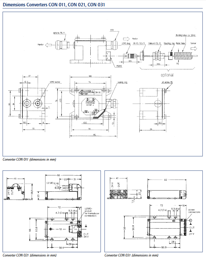
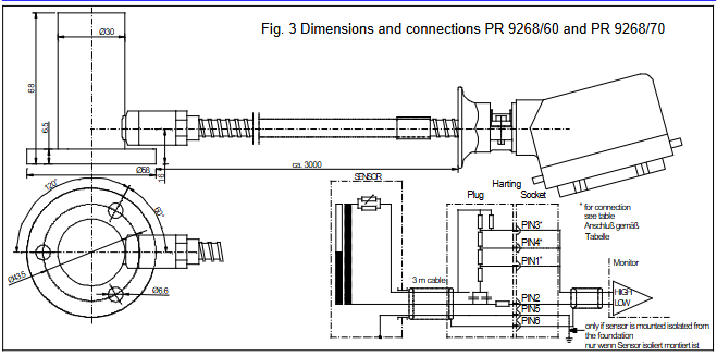
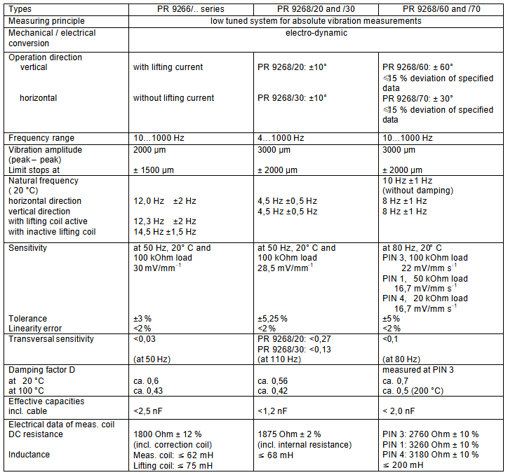
The PR 9266/.. And PR 9268/.. Series electric absolute vibration sensors are designed specifically for measuring the absolute vibration of machines and are part of the MMS 6000 and MMS 3000 rotating machinery monitoring systems. Its working temperature range can reach 200 ° C, using seismic function principle, easy installation, high sensitivity, sturdy structure suitable for industrial applications, with splash proof characteristics, protection level of IP 55 or IP 65, with two frequency ranges of 10 Hz to 1000 Hz and 4 Hz to 1000 Hz. When used in conjunction with safety barriers (Zone 1), the safety level is EEx ib II B/II C.
Application scenarios
The absolute vibration can be measured in frequency ranges of 10… 1000Hz and 4… 1000Hz, with vibration amplitudes of up to 2mm and 3mm (peak to peak), respectively. It can provide an electrical signal proportional to the vibration velocity. Suitable for various types of turbomachinery, fans, compressors, gearboxes, pumps, coal mills, and other machines. Among them, PR 9268/60 and PR 9268/70 are particularly suitable for high-temperature environments, such as gas turbine applications, and also include electrical adaptation, which can replace the original AEG Kanis Group’s MMG 033 and MMG 1033 absolute vibration sensors, and provide three different sensor sensitivities according to the type of measurement amplifier.
Functional Principles and Design
Measurement element: composed of seismic mass blocks with coils, suspended on diaphragm springs, moving in the circular gap of permanent magnets, and guided by diaphragm springs in the longitudinal direction (measurement direction) of the measurement element.
Working mode: The sensor operates above the resonance frequency (different models have resonance frequencies between 4 and 13 Hz), while the seismic mass remains stationary. Due to the vibration of the sensor housing, an electrical signal proportional to the vibration velocity is generated.
Damping: The damping of the measuring element is achieved through a damping cylinder or external device, with a damping value of about 0.6 and good linear characteristics throughout the entire frequency range.
Special design: Measurements below the resonance frequency can be corrected by corresponding amplitude response; When the vibration amplitude is too high, the mechanical limiter will reduce the maximum amplitude of the seismic system; Each sensor is designed for a measurement direction (vertical or horizontal). The PR 9266/.. Series sensor has an additional lifting coil, which adjusts the center position of the seismic element by inputting a lifting current of up to 7mA into the coil; The PR 9268/.. Series sensors can directly input the boost current into the measurement coil, but this current must be separated from the measurement signal. The measurement amplifier of MMS 6000 supports the operation of absolute bearing vibration sensors and provides boost current.
Vibration amplitude (peak to peak) and limiter position: 2000 µ m, limiter at ± 1500 µ m 3000 µ m, limiter at ± 2000 µ m 3000 µ m, limiter at ± 2000 µ m
Damping coefficient (20 ° C/100 ° C): approximately 0.6/approximately 0.43, approximately 0.56/approximately 0.42, measured at PIN 3, approximately 0.7/approximately 0.5 (at 200 ° C)
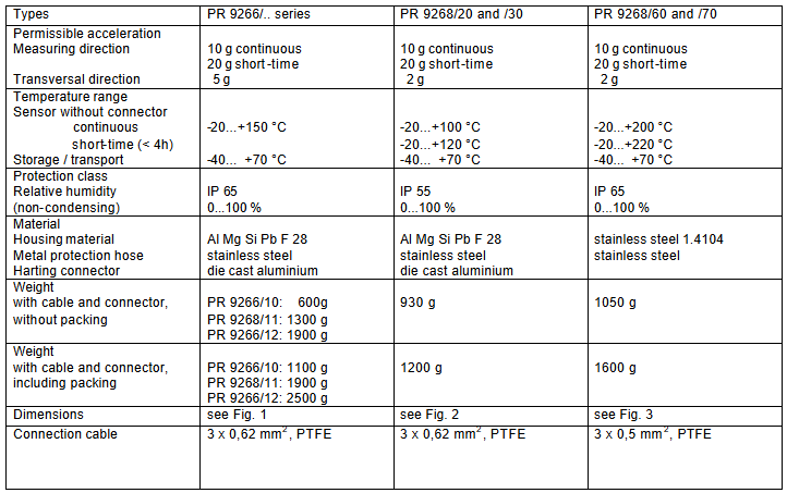
Allowable acceleration (measurement direction/lateral): 10 g continuous, 20 g short-term/5 g 10 g continuous, 20 g short-term/2 g 10 g continuous, 20 g short-term/2 g
Temperature range (sensor without connector, continuous/short time (<4h)/storage and transportation): -20…+150 ° C/-20…+170 ° C/-40…+70 ° C -20…+100 ° C/-20…+120 ° C/-40…+70 ° C -20…+200 ° C/-20…+220 ° C/-40…+70 ° C
Protection level/relative humidity (non condensing): IP 65/0… 100% IP 55/0… 100% IP 65/0… 100%
Materials (shell/metal protective hose/Hart connector): Al Mg Si Pb F 28/stainless steel/die cast aluminum Al Mg Si Pb F 28/stainless steel/die cast aluminum stainless steel 1.4104/stainless steel/die cast aluminum
Connecting cable: 3 x 0.62 mm ², PTFE, 3 x 0.62 mm ², PTFE 3 x 0.5 mm ², PTFE
Ordering Instructions
The order model format is PR 926X/X-XX0, and the meanings of each part are as follows:
The PR 9266 series corresponds to the number “6”, and the PR 9268 series corresponds to the number “8”.
Base type: 0 for no base, 1 for triangular base, 2 for cubic base.
Measurement direction: PR 9268/20 is vertical, PR 9268/30 is horizontal, PR 9268/60 is vertical (high temperature 200 ° C), PR 9268/70 is horizontal (high temperature 200 ° C).
Cable length: 0 is 3m, 1 is 5m, 2 is 8m, and 3 is 10m.
Cable end (only PR 9268/60 and/70 with Hart connector): 0 is Hart connector, 1 is open cable end.
Flexible metal protective tube: 0 with strap, 1 without strap.
Overview of FX Series Positioning Servo Drive System
The FX series positioning servo drive system is a servo solution with over ten years of application history. By combining FX drivers with PCM modules, it can solve various common applications and is the foundation of the “Motion Made Easy” series solutions. This system is based on the 2000 Emerson Motion Control Servo Solution Catalog information and adopts a fully digital design, suitable for multiple torque ranges. It is compatible with DX series (0-120 lb in) and BL series (120-1000 lb in) rotary transformer feedback servo motors, and some models have UL certification, Canadian UL certification, and CE certification.
Core Features
Flexible power and torque: Supports multiple power inputs and can provide continuous torque from 0-1000 lb in. Some models have IP65 protection and brake versions.
Convenient programming: Use Emerson Motion Control’s PCXWin or DOS version PCX software, with fill in the blank operation for easy programming.
Rich I/O and operation modes: Standard equipped with 8 inputs and 4 output lines (10-30 VDC), supporting sinking or sourcing modes; The operating modes include integral locator, simulated speed, simulated torque, and pulse follower.
Scalability: Application modules can be installed to increase I/O, memory, and special application functions. The basic module can start up to 100 steps of motion sequence programs, and adding application modules can reach 1024 steps.
Communication and Storage: Equipped with RS-232 communication interface, with a maximum baud rate of 19.2 Kbaud, it can daisy chain up to 31 FX drives on a single communication link; Non volatile memory can store up to 32 sets of index parameters.
Other features: Supports linear or modified sine motion curves, can be scaled in user-defined units such as inches, feet, millimeters, etc., has auxiliary logic power supply to maintain critical driving information in case of bridge power loss, is equipped with LED display for displaying operation and diagnostic status, and offers a two-year extended warranty.
CE marking FX system
Certification and Scope: Compliant with EMC Directive 89/336/EEC and bearing the CE mark, with a continuous torque range of 8-120 lb in, a peak of 200%, and a maximum duration of 1.5 seconds. The amplifier is UL certified and the motor is UL approved, providing complete motion control system components.
Configuration and wiring: The CE marked FX driver has the same functionality and performance specifications as the standard FX driver, and is set using PCX programming software; There are two system wiring methods that meet CE grounding and shielding requirements, both requiring power lines and motor power filters.
Application module
The FX series offers a variety of application modules that can be easily installed on any FX driver front-end, enabling advanced positioning functions such as phase synchronization, proportional control, web control, and rotary tool cutting. It is programmed using the same PCX software as the basic FX driver, with parameters stored in non-volatile memory and movable between different drives. The main application modules include:
PCM-11 motion program controller: suitable for various applications such as composite indexing and packaging machinery.
PCM-14 slip compensator: used for slip compensation, automatic coil feeding and other scenarios.
PCM-15 proportional controller: capable of implementing functions such as flying shears and electronic spools.
Other modules, such as PCM-16 phase synchronization controller and PCM-17 random feed controller, each have their specific application areas.
Operation mode
Position control mode: The microprocessor executes user-defined motion control functions and can store multiple indexes. After adding application modules, the index storage capacity and functions can be expanded.
Pulse sequence following mode: Each received pulse generates incremental axis rotation, which can directly replace existing stepper positioning systems.
Simulation mode: includes two options: simulated speed and simulated torque, and all motion and system limitations are effective in this mode.
Software and Programming
PCX programming software: intuitive and simple, no need for advanced programming language knowledge. After the user inputs the motion parameters, the software completes the relevant operations and can complete the system settings in a short time.
Configuration and parameter settings: including driver parameter configuration, motion parameter definition (such as jogging, indexing, etc.), I/O settings, etc.
Specifications and Performance
System specifications: Different models of FX drivers have specific parameters in terms of recommended line current, motor torque, motor rotor inertia, rated power, maximum motor speed, and the shortest time to reach maximum speed.
Brake specifications: Each model of brake has clear data on maintaining torque, inertia, weight, coil voltage and current, engagement and release time, etc.
Driver specifications: including input power supply voltage, control mode, serial interface, programming method, diagnostic indicators, noise immunity, I/O circuit specifications and capacity, resolution, performance, motor housing, environmental specifications, etc.
Options and attachments
Including operator interface terminals, synchronous encoders, serial interface cables, external shunt resistors, main frequency generators, AC line filters, 525 programmable motion controllers, as well as various cables and miscellaneous accessories, it can meet different application needs.
Ovation ™ The control system is a key component of Emerson PlantWeb’s digital architecture, a distributed control and SCADA system designed specifically for the global power generation and drainage industries. It combines Emerson’s over 50 years of professional experience in complex operations control and management, and can enhance the availability, reliability, and environmental compliance of factories for users, helping to achieve operational excellence and sustainable competitive advantages.
Core advantages
Progressiveness and adaptability of technology
Using commercial off the shelf technology to provide a powerful and adaptable platform, giving users greater operational flexibility.
Support the gradual evolution of the system, which can be modified and expanded with process expansion or technological progress to avoid rapid system obsolescence and protect engineering investment.
high reliability
Build hardware platforms, operating systems, and network architectures based on industry standards to reduce maintenance costs, and the hardware can be gradually upgraded.
The controller has a fully redundant design to ensure the reliability and safety required in harsh applications.
Excellent control performance
With over 100 standard algorithms and the ability to embed advanced control algorithms, it can be combined with model predictive control and industry-specific advanced applications to reduce process fluctuations and optimize performance under full range factory operating conditions.
Seamless integration with intelligent field devices and widely adopted bus standards such as HART, Foundation fieldbus, Profibus, DeviceNet, etc.
Convenient operation and programming
The operator workstation provides a clear, concise, and easy to navigate process view, including high-definition process graphics, built-in trend data, advanced system diagnostic displays, and more.
The engineer workstation provides an intuitive and easy-to-use graphical interface, and its development studio adopts drag and drop functionality and object-oriented system configuration methods to reduce the learning curve and simplify development.
System composition and functions
hardware components
Controller and I/O: A fully redundant controller and I/O component based on Intel processors, designed to be compact and modular, reducing footprint and power consumption, supporting multiple digital buses and remote I/O.
Workstation: The operator workstation adopts a ready-made desktop PC and standard Windows operating system; Engineer workstation integrates operator workstation functions and system configuration tools.
Software and Applications
Includes tools such as control builder, graphics builder, security builder, AMS suite (Intelligent Device Manager) for predictive maintenance, and OPC connectivity functionality.
Equipped with embedded applications, such as boiler/turbine coordination control and emission monitoring for power generation projects; SCADA interface and PLC integration for water supply, drainage, and renewable energy applications.
Network and Connectivity
Adopting unmodified Fast Ethernet as the control and information highway, it supports connection with almost all Ethernet devices, has multi network capabilities, and can integrate multiple Ovation systems.
Supports multiple standard data exchange protocols (such as OPC, NetDDE, ODBC, etc.) and provides direct connections with PLC and OEM control systems.
Ovation Security Center provides additional security features and services to enhance and manage system network security.
PlantWeb Architecture Integration
As a key component of PlantWeb’s digital architecture, Ovation offers a range of integrated products and features that enable asset management, process control, and management execution through intelligent field devices, industry standard platforms, and integrated modular software. The PlantWeb architecture can reduce installation costs for new projects, improve factory efficiency, and support multiple digital device communication protocols.
Applicable fields
Mainly targeting the power generation and water supply and drainage industries, it has been successfully applied in thousands of related projects and can meet the control needs of complex processes in these industries.
The Ovation I/O Reference Manual (R3-1150 Rev 3) is a reference manual written by Emerson Process Management for the input/output (I/O) modules of Ovation distributed control systems. This manual provides detailed information on the characteristics, specifications, installation, configuration, wiring, and diagnosis of various I/O modules, aiming to provide users with comprehensive guidance on the use of I/O modules, suitable for industrial control fields such as power generation and water supply and drainage.
Main content
Noise suppression technology (Section 2)
Analyzed the causes and suppression techniques of electrical noise, including background knowledge of noise, identification methods (based on energy level, frequency, source), noise sources (inductive devices, AC/DC power circuits, etc.), noise classification (high, medium, low, extremely low), noise suppression methods (filtering, isolation, etc. of digital and analog signals), as well as analog signal shielding techniques and common input considerations.
Overview of I/O Modules (Section 3)
Outlined the features of Ovation I/O modules, such as support for local and remote configuration, modular design, DIN rail installation, etc; Introduced the composition of the module (standard module includes electronic module, personality module, and base unit, relay output module includes electronic module and base unit); It also covers the installation, configuration and status of modules, diagnostic LEDs, user replaceable fuses, and personalized module jumpers, and provides environmental specifications for I/O modules.
Detailed Introduction to Various I/O Modules (Sections 4-25)
Detailed explanations were provided for 13 bit analog input module, 14 bit analog input module, high-speed analog input module, analog output module, contact input module, compact contact input module, digital input module, compact digital input module, digital output module, HART analog input module, HART analog output module, link controller (LC) module, loop interface module, pulse accumulator module, etc., including module description, group division, external power supply, technical specifications, terminal block wiring information, on-site connection wiring diagram, address location, and diagnostic LED.
Ovation Local I/O and Remote I/O (Sections 26-27)
Introduced the overview, characteristics, components, cable requirements, configuration, and diagnostic LED of local I/O and remote I/O.
Appendices A-D
Contains supplementary information such as Q-Line card type, Ovation electronic ID, CE mark specifications, and instructions for using external power supply.
Summary of Changes
This revised version has added CE marking information for most chapters, added multiple personalized module fuses in Table 3-3, added relevant chapters and tables for high-speed analog input module, 16 bit HART analog input module, and 14 bit HART analog output module, replaced module group numbers in Table 27-1, added module group numbers for remote node controller module, replaced Appendix C, added warning information to the wiring diagram of the 14 bit analog input module, added part numbers to the warning information of the relay output module, corrected the part numbers of the relay output base component, added a reference to U3-1005 at the mention of U3-1000, defined a new firmware level for valve positioner (RVP), used graphics for RVP calibration, Added configuration commands kServo and kServoDB The troubleshooting content for the valve positioner and MAU subsystem has been added with an optical guide, and all chapters have miscellaneous clarifications and/or corrections.
Core Features
Modularity and compatibility: The I/O module adopts a modular design, which is easy to install, configure, and replace, and is compatible with previous models. It provides migration programs to update the control logic and database of old models.
Reliability and safety: The modules have good isolation performance, fault diagnosis capability, and redundancy design (some modules), which comply with relevant standards (such as IEC 61131-3). Some modules have obtained Achilles Level 1 certification to ensure stable and reliable operation of the system.
Wide applicability: Supports multiple signal types (analog, digital, pulse, etc.) and communication protocols (such as HART) to meet the control needs of different industrial scenarios.
Detailed technical specifications: Each module provides precise technical parameters such as input/output range, resolution, accuracy, sampling rate, isolation voltage, working environment conditions, etc., providing accurate basis for user selection and use.
The HART (Highway Addressable Remote Transformer) high-performance analog input module is a standard Ovation I/O module, updated to the 3rd edition of the Ovation I/O Reference Manual on March 3, 2003, and should be placed between Chapters 14 and 15. It provides 8 globally isolated 4-20mA analog inputs, equipped with HART transceivers, each of which is connected to a dedicated UART through optical isolation communication to maximize HART communication. This module can communicate with HART devices and support “smart” field devices. The analog 4-20mA signal, digital communication, and sometimes power supply of such devices can coexist on the same pair of wires.
Module group
Electronic module: There is only one set of 5X00106G01, which can connect 8 current loop signals with an input range of 4-20mA.
Personality module: There is only one set of 5X00109G01, which includes a printed circuit board component with 8 fuse inputs and user accessible jumper wires. It can be configured with transmitters for on-site or local power supply channels one by one.
Power supply
The logic circuit is powered by a standard+24V Ovation main power supply.
The on-site power supply is provided by a 24V auxiliary power supply, including all 4-20mA loop power supplies, A/D converters, and other output channel components. It can be a standard 24V Ovation auxiliary power supply or an external power supply provided by the user.
It is recommended to use the Ovation cabinet’s auxiliary+24V DC power supply. If an external auxiliary power supply is used, its noise should be ≤ 1.2Vrms.
All modules using auxiliary power sources (including HART modules) must use shielded I/O cables to suppress coupling noise and transients.
Technical specifications
Number of channels: 8
Input range: 2.5 to 25mA, with under range and over range checks
Full operating temperature range accuracy: ± 0.24% full-scale value (20mA)
Sampling rate (per second): 20 times when configured for 60Hz suppression; 25 times when configured for 50Hz suppression
Dielectric isolation between channels: 1000VAC/VDC, lasting for 1 minute; Channel and logic: 1000VAC/VDC, lasting for 1 minute
Working temperature range: 0 ° C to 60 ° C (32 ° F to 140 ° F)
Humidity (non condensing): 0% to 95%
Module power consumption: main power supply: typical 4.1W, maximum 4.5W; auxiliary power supply: typical 3.84W (20mA x 8 loops x 24V); Module Dissection: Typical 5.06W (Emod+Pmod)
Input impedance: 300 ohms
Common mode rejection ratio: 120dB for DC or nominal (50/60Hz) line frequency ± 1/2% and harmonics; typical 100dB for nominal line frequency ± 5% and harmonics
Personalized module and wiring information
Personality module: Each channel has a 1/20A fuse for loop protection, and each channel has a pair of user accessible jumpers that can be configured as locally or on-site powered transmitters according to the channel. The fuses and jumpers can be accessed from the top of the module.
Wiring information: There is a simplified wiring diagram label on the side of the personality module, indicating the connection method between the on-site wiring and the base unit terminal block. Each channel has two wiring configurations (depending on the transmitter configuration for local or on-site power supply), and relevant abbreviations are defined.
Register Mapping and Function
The module has 16 direct registers, including indirect memory indexes, analog input channel data, calibration registers, channel error bits, module configuration/status registers, HART enable registers, etc. Among them, module status register # 13 (hexadecimal D) can be read through the operator station’s point information window, and word address # 12 (hexadecimal C) is used to report errors in 8 input channels.
Diagnostic LED
P (green): LED with normal power supply, lights up when the+5V power supply is normal.
C (green): Communication is normal LED, which lights up when the controller communicates with the module.
I (red): Internal error LED, which lights up when any error occurs inside the module (except for loss of external auxiliary power supply). Possible reasons include forced error bits in the controller setting module, loss of communication with the controller, etc.
1-8 (green): Eight channel LEDs indicate firmware status during module startup and HART communication activity and analog input health during normal operation.
Other
The requirements for on-site wiring cables can refer to the HART FSK physical layer specification (HFC_SPEC-54).
The point data register is located at positions 2-9, corresponding to analog input points 1-8 respectively.
The HAI, HAO, and IAH modules are capable of retrieving additional variables from field devices, known as “multivariate”, including PV (primary variable), SV (secondary variable), TV (tertiary variable), and QV (quarterly variable).
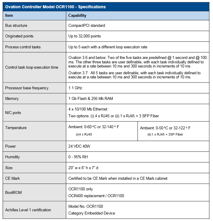
Ovation ™ The Controller Model OCR1100 is a controller in Emerson’s Ovation distributed control system, known for its precise control and excellent performance, suitable for critical task operations such as power generation and water supply and drainage. It can execute simple or complex adjustment and sequential control strategies, complete data acquisition functions, and interface with Ovation network and various I/O subsystems, generating up to 32000 points.
Main characteristics
Reliability and safety: It has the ability to control critical tasks safely and reliably, and can achieve disturbance free automatic fault transfer between redundant controllers; Obtained Achilles Level 1 certification, compliant with IEC 61131-3 standard.
Efficiency: Using Intel processors, it can simultaneously execute up to 5 process control tasks with a wide range of loop speeds (10 milliseconds to 300 seconds), and different software versions have different settings for task loop speeds.
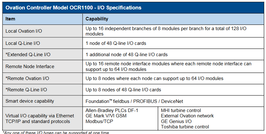
Interface and compatibility: Can interface with local and remote Ovation and WDPF I/O interfaces; Integrate interface with digital bus through Ovation I/O module; Capable of integrating virtual I/O and connecting to third-party OEM systems via Ethernet protocol; Supports multiple smart device protocols, such as Foundation ™ Fieldbus, PROFIBUS, DeviceNet, etc.
Storage and functionality: non-volatile storage applications, point databases, configuration information, and operational adjustment constants; The event sequence function with a resolution of 1 millisecond can record the sequence of digital input state changes and can also be used for control schemes; Sensors/limit checks, alarm processing, engineering unit conversion, database storage, etc. that can handle process points.
Structural features: small size, low power consumption, fanless operation; Adopting an open architecture based on CompactPCI ® Bus design and real-time operating system facilitate the integration of new technologies and protect software investments; The hardware is based on industry standards and uses Intel processors and CompactPCI bus technology, making it easy to upgrade and port.
Controller type
Simulator controller: using simulated I/O instead of actual hardware I/O system, integrating control scheme with process model or simulation interface, can be used for factory acceptance testing, etc.
Advanced controller: executes authorization algorithms with advanced functions, such as autoregression, dynamic matrix, fuzzy logic, etc.
Virtual Controller: Reproduces Ovation hardware controllers using real-time operating systems on Windows based platforms, mainly used for Ovation simulation solutions, without hardware I/O support.
Redundant functions
Redundant configuration: Key components (such as network interfaces, processors, power supplies, etc.) have multi-level redundancy, and the standard hardware configuration is a passive backplane, with a main controller and a backup controller installed.
Working mode: The main controller directly accesses I/O in control mode, performs data acquisition and control functions, and monitors the backup controller; The backup controller performs diagnostics in backup mode, monitors the main controller, and keeps data updated by polling the main controller database.
Automatic fault transfer: When the main controller fails, the backup controller immediately executes the control application program to achieve disturbance free switching. Multiple events can trigger fault transfer, and the fault processor can restore the backup role after repair.
Technical specifications
Basic parameters: The bus structure is based on the CompactPCI standard; Processor reference frequency 1.1 GHz; 1 GB of flash memory and 256 Mb of RAM; Four 10/100 Mb Ethernet NIC ports with two options; The working environment temperature and humidity have corresponding ranges; The size is 20 “w x 8” h x 7 “d; The power supply is 24 VDC 40W.
I/O capability: Supports multiple I/O systems, with up to 16 independent branches for local Ovation I/O, totaling 128 modules; 48 cards per local Q-Line I/O node, and expanding Q-Line I/O can add 1 node; Remote node interfaces also have corresponding support capabilities; Capable of virtual I/O through Ethernet TCP/IP and standard protocols.
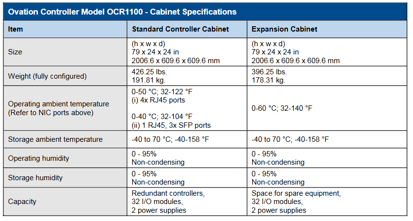
Cabinet specifications: The standard controller cabinet and expansion cabinet have the same size (79x24x24 inches), but there are differences in weight, capacity, etc; There are also regulations on the temperature and humidity range for work and storage.
Other information
The controller and I/O modules are both installed on DIN rails, and the cabinet configuration is flexible with multiple options. Customized cabinets can also be provided.
The hardware platform is constantly evolving and compatible with previous models, providing migration programs to update old model control logic and databases.
Copyright belongs to Emerson from 2017 to 2019. Product information is for reference only and sales are subject to relevant terms. The company reserves the right to modify product design or specifications.
PAC8000 Remote I/O is a fully modular I/O solution suitable for general and hazardous area applications. Based on the carrier system, it supports multiple modules and I/O functions, including intrinsic safety signals. Its open architecture can communicate with various different fieldbuses by selecting appropriate types of bus interface modules (BIM). This product is designed to withstand extreme temperatures, humidity, corrosive substances, impacts, and vibrations, providing full specification performance even in the harshest environments and performing well in ATEX environments. All components can be installed and operated live in Zone 2/Division 2 and ATEX Zone 1 hazardous areas, and I/O includes types that can be directly connected to intrinsic safety (Exi) or increased safety (Exe) field wiring, seamlessly integrated with PACSystems solutions, and connected to RX3i and RSTi EP controllers via PROFINET or Modbus TCP.
Main characteristics
Operation in harsh and hazardous areas: It can operate within the range of -40 ° C to+70 ° C, withstand ISA Level G3 corrosion, 30g impact, and 5g vibration, and is suitable for Class I, Division 2, and Zone 2 hazardous areas. Its I/O module field wiring includes intrinsic safety (Exi) and increased safety (Exe) options, and also supports UL HAZLOC C1D1 and ATEX Zone 1 hazardous areas.
High availability: Supports PROFINET system redundancy (PNSR), enabling synchronized independent controllers to serve I/O and seamlessly transition from active controllers to backup controllers. Controllers can be up to 10 kilometers apart and can handle physical interrupts.
Rich I/O modules: In addition to analog and digital I/O, there are multiple modules to choose from, including options for low-level instruments, AC power supply, and intrinsic safety signals. There are 4, 8, 16, and 32 channel modules, and all modules provide comprehensive diagnostic information.
Easy troubleshooting and machine setup: PAC8000 I/O can be easily configured using the integrated PAC Machine Edition (PME) software. If PROFINET is used, configuring through GSDML files is even simpler. PME software is compatible with all PACSystems CPUs, requiring only one tool for small to large applications and simplifying HMI development.
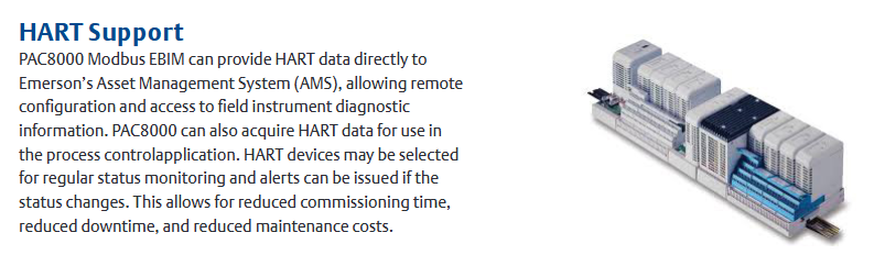
HART support: PAC8000 Modbus EBIM can directly provide HART data to Emerson’s Asset Management System (AMS), allowing remote configuration and access to on-site instrument diagnostic information. It can also obtain HART data for process control applications. HART devices can be selected for routine status monitoring, and alarms can be issued when the status changes, reducing debugging time, downtime, and maintenance costs.
Specification parameters
Installation format: DIN rail.
Network interfaces: PROFINET, Modbus/TCP.
Gateway/Bridge: HART.
Network redundancy: MRP, dual LAN.
System redundancy: PNSR or Modbus/TCP.
I/O redundancy: Dual redundancy.
Media support: Copper cables and multimode optical fibers.
Isolation: Galvanic isolation, DI, DO, AI, AO are all isolated.
Hot swappable: supported.
Environmental parameters: IP20 protection level, operating temperature from -40 ° C to 70 ° C, with normal coating, resistant to ISA Level G3 corrosion, able to withstand 30g impact and 5g vibration.
Institutional certification: UL, UL HAZLOC C1D1, CE, ATEX Zone 1, intrinsic safety certification, as well as classification society certification (such as Lloyd’s Register).
The A6500-LC linear adjustable displacement sensor (LVDT) preamplifier is a single channel device used to connect half bridge inductive sensors or LVDT sensors with CSI 6500ATG. It provides excitation voltage for the sensor and proportionally converts the displacement signal measured by the sensor into an output voltage range suitable for the A6500UM universal measurement card.
Main parameters
Measurement characteristics
Measurement range/absolute value: There are multiple ranges when used with different types of sensors, such as ± 12mm/24mm when using PR 9350/01, ± 25mm/50mm when using PR 9350/02, etc.
Output voltage swing/range: varies depending on the sensor model, for example, about 4.8V/7.6 to 12.4V when using PR 9350/01, about 9.2V/5.4 to 14.6V when using PR 9350/04, etc., and is symmetrical around 10V.
Temperature deviation: When using PR9350/01, the standard is ± 5.0%, and when using PR9350/02 to/12, the standard is ± 2.5%.
Measurement accuracy: Deviation from standard straight line<± 2%/measurement range (4.8 to 12.2V).
Replace the measurement error of A6500-LC:<1%.
Signal output: The standard signal voltage output range is+2 to+18V (short circuit protection); The output voltage limit is approximately+1.1 to+23.3V @+24V supply voltage; Jumping<10mV peak value; The resistance is about 100 Ω; The connection time is about 200ms; the frequency range is 0 to 10Hz (-3db).
Power supply
Power supply voltage range:+22.5V to+32VDC.
Current loss:<30mA.
The influence of power supply voltage on output signal:<0.1%/V.
Overvoltage protection:<60V (using SELV/PELV power supply).
Sensor supply voltage: approximately 2.2Vrms, 5kHz.
Environmental parameters
Protection level: IP20 IEC 60529.
Operating temperature: -35 ° C to+75 ° C (-31 ° F to 167 ° F).
Storage temperature: -35 ° C to+85 ° C (-31 ° F to 185 ° F).
Relative humidity: 5 to 95% (no condensation).
Vibration: 0.35mm (0.014 in), 10 to 55Hz; 5g,55 to 150Hz, According to EN60068-2-6.
Impact: 15g according to EN 60068-2-27, 6ms, 5000 impacts per axis.
The A6370 monitor is part of the AMS 6300 SIS overspeed protection system and is installed in a 19 inch rack (84HP width and 3RU height) in combination with the A6371 system backplane. A set of AMS 6300 SIS consists of three protection monitors (A6370) and one backplate (A6371), suitable for eddy current sensors, Hall element sensors, and magnetic (VR) sensors.
Main parameters
Sensor voltage supply
Nominal supply voltage: -24.5 V ± 1.5V DC, with short-circuit protection and electrical isolation.
Maximum current: 35 mA.
Signal input
Eddy current and Hall element sensors: Input signal voltage range of 0 V to 26 V (±), with reverse polarity protection, limited range of ± 48 V, frequency range of 0 to 20 kHz, typical input resistance value of 100 k Ω.
Magnetic (VR) sensor: Input signal voltage range minimum 1 Vpp, maximum 30 V RMS, frequency range 0 to 20 kHz, typical input resistance value 18 k Ω.
Digital input (backplane)
Input quantity: 4 (electrically isolated, all digital inputs are grounded), including test value 1, test value 2, enable test value, reset latch.
Logic low level: 0 V to 5 V; Logic high level: 13 V to 31 V (open circuit).
Output quantity: 7 (short circuit protection), including outputs 1 to 6, channel normal (COK).
Logic low level:<100 mV; Logic high level: -2 V (system supply voltage).
Maximum current: 25 mA.
Pulse output
Backboard: 3, open collector emitter, current limiting, electrical isolation; Maximum voltage 31.2 V; maximum current 16 mA at 24 V; frequency range 0 to 20 kHz.
Front panel: 1 (short circuit protection); Voltage ranging from 0 to 5 V (TTL signal); Frequency range 0 to 20 kHz; The typical output impedance is 10 k Ω.
Sensor output (front panel)
Output quantity: 1 (short circuit protection).
Voltage: 0 to 3.9 V, coefficient 0.15 ± 3%.
Frequency range: 0 to 20 kHz.
Typical output impedance value: 10 k Ω.
Communication
USB: Configuration interface, USB B-type.
RS 485: Up to 32 devices with baud rates of 38400, 57600, and 115200 baud.
Profibus DP (A6370D/DP only): up to 31 devices, with a data transmission rate of up to 12 Mbit/s.
Reaction time
Speed:<measurement time+8 ms.
The typical reaction time at 3000 min ⁻¹ is 35 ms in the “once per revolution” mode and 12.5 ms in the “automatic” mode.