Call us 24/7uaedcs@163.com
Welcome to the official website of CNIACS Automation Technology Co., Ltd!
Call us 24/7uaedcs@163.com

KOLLMORGEN P70360 High Performance Microstep Driver

Basic Information

Core positioning: P70360 is an AC input micro stepper driver that supports 120/240 VAC power supply, with a maximum output current of 2.5 A RMS (peak 3.5 A RMS) and integrated Dynamic Smooth ™ (Dynamic smoothing) Multi-Stepping ™ (Multi step) Encoderless Stall Detection ™ (No encoder blockage detection) and other patented technologies should be used in conjunction with Kollmorgen recommended stepper motors (such as T2x/N3x/K3x series), and parameter configuration can be achieved through switches or P7000Tools software.

Version iteration: The document has undergone 7 revisions (1-G version), with the latest G version mainly updating outdated pin numbers, adding J4-18 pin warnings, updating brand logos, and revising the motor selection section to ensure compatibility with firmware version 2.10 and above.

Core technical parameters and hardware characteristics of the driver

(1) General Technical Parameters

Category parameter item specification

Power characteristics: Input voltage 120/240 VAC (50/60 Hz), corresponding to DC bus voltage of 320 VDC (optional 160 VDC bus)

Maximum output power 350 W (240 VAC input)

Bus voltage protection undervoltage fault 130 VDC, overvoltage fault 440 VDC, regenerative voltage 420 VDC

Surge current peak 30 A (pulse width 4 ms), recommended slow melting fuse 7 A

Motor adaptation motor inductance range: 320 VDC bus: 50~200 mH; 160 VDC bus: 7~30 mH

The maximum length of motor cable is 20 meters (24 AWG cable)

Step resolution of 200~50000 steps per motor rotation (set through S2-2~S2-4 switches)

I/O Characteristics Step/Direction Input Voltage 2.5~5.5 VDC, Current 5~20 mA, Maximum Frequency 2 MHz, Minimum Pulse Width 250 ns

Universal input (9 channels) voltage 3.5~24 VDC, current 10 mA, response time ≤ 250 μ s

Universal output (2 channels) maximum voltage 30 VDC, maximum current 10 mA, response time ≤ 250 μ s

Environmental adaptability working temperature 0~40 ° C

Storage temperature -20~+70 ° C

Humidity 90% relative humidity (no condensation)

Altitude ≤ 1500 m (5000 ft)

Pollution level II

(2) Hardware features and optional configurations

core functionality

Dynamic Smoothing ™): The second-order low-pass filter reduces motion impact and mechanical resonance, and sets the smoothing level (minimum/moderate/severe/aggressive) through S2-8/S2-9 switches.

Encoder less Stall Detection ™): By monitoring the deviation between the instruction position and the actual position through the internal motor model, if the deviation exceeds 2 full steps, a fault will be triggered and activated through the S2-12 switch.

Current Reduction: After the motor is stationary for 100 ms, it automatically reduces the current to 75% of the rated value (the ratio and delay can be adjusted through software), and the S2-10 switch controls enable/disable.

Multi Stepping ™): Enhanced filtering function, smoothing low resolution input (such as 200/400 steps/rev) into micro step output, with S2-11 switch enabled.
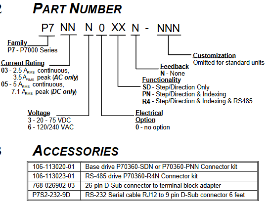
Model difference

P70360-SDN: Basic version, only supports step/direction control, default universal input configuration is Jog ±/EOT ±/fault reset.

P70360-PNN: Advanced version, supporting step/direction and indexing functions, with additional MV SEL 1-4 inputs for multi speed selection.

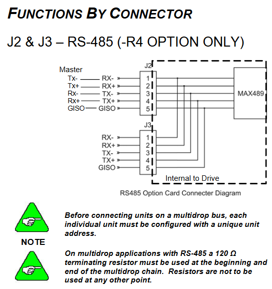
P70360-R4N: Equipped with RS-485 communication version, supports multi machine networking (requires unique node address configuration), and adds J2/J3 connectors for RS-485 bus.

Hardware installation and electrical wiring specifications

(1) Mechanical installation requirements

Installation preparation

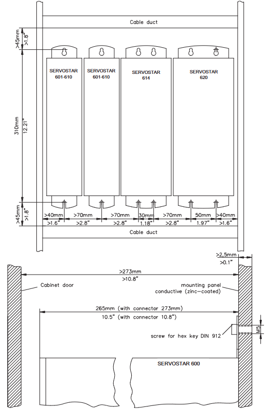
Installation surface: It should be a cold plate (recommended aluminum), fixed with 8-32 or M4 screws, and the driver should be installed upright (with the heat sink fins facing left), leaving at least 25.4 mm (1 in) of heat dissipation space around to avoid direct exposure to heat sources.

Temperature control: When the temperature of the heat sink exceeds 70 ° C, the driver will overheat and shut down. If the ambient temperature exceeds 40 ° C, it is necessary to increase fan cooling or reduce the load duty cycle.

installation dimensions

Basic version (without RS-485): Length 170.18 mm (6.700 in), Width 132.21 mm (5.205 in), Height 52.324 mm (2.060 in).

Equipped with RS-485 version: length 170.18 mm (6.700 in), width 132.21 mm (5.205 in), height 58.217 mm (2.292 in).

(2) Electrical wiring specifications

Wiring safety and sequence

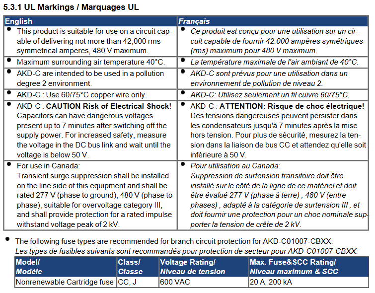
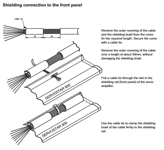
Power off operation, ensure that the drive capacitor is discharged (after power off for ≥ 2 minutes, measure the DC bus voltage<40 V), all power cables and control cables need to be separately shielded, and both ends of the shielding layer should be grounded.

The distance between the power cable (motor/power supply) and the control cable (step/direction/I/O) should be ≥ 20 cm to avoid cross interference; When the cable length exceeds 25 meters, Kollmorgen 3YL-20 choke coil is required (such as SERVOSTAR 601-606 with 4 × 1 mm ² cable).

Core connector definition

J4 (26 pin command I/O): includes step (J4-1/2), direction (J4-3/4), enable (J4-5/6) inputs, fault output (J4-7/8), 9-channel universal input (J4-10~18), universal output (J4-21/22), and 5V power supply (J4-19/25).

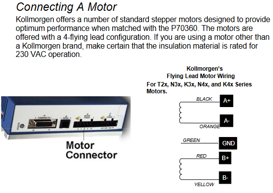
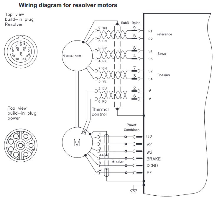
J6 (motor power supply): 4-pole connector, A+/A – (black/orange), B+/B – (red/yellow) connected to the motor winding, PE (green and yellow stripes) connected to the motor casing, pay attention to the motor direction (swapping A ± or B ± can be reversed).

J7 (AC power supply): 4-pin connector, J7-1 is connected to 120/240 VAC live wire, J7-2 is connected to 240 VAC neutral wire, J7-3 is connected to 120 VAC neutral wire, J7-4 is connected to protective earth (PE), and it is forbidden to connect 240 VAC to J7-3.

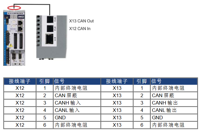
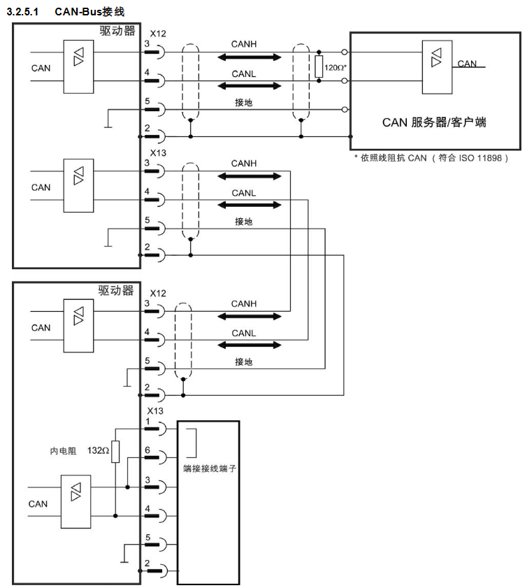
J2/J3 (RS-485, R4N version only): 5-pin connector, J2-1/RX+, J2-2/RX -, J2-3/TX -, J2-4/TX+, J2-5/GOS (isolated ground), with 120 Ω terminal resistors connected at the beginning and end of the bus.

Typical wiring scheme

Differential step forward/direction: The controller differential output is connected to J4-1 (STEP+)/J4-2 (STEP -), J4-3 (DIR+)/J4-4 (DIR -), and the cable uses shielded twisted pair, with both ends of the shielding layer grounded.

Open collector electrode single ended signal: The controller’s open collector electrode output is connected to J4-1 (STEP+)/J4-3 (DIR+), J4-2/J4-4 are grounded, and an external pull-up resistor is required (when the voltage is greater than 5V, a current limiting resistor needs to be connected in series, the formula R CL=(V s − 5) × 100).

Universal input (such as Jog+): When using an internal 5V power supply, connect J4-14 (DIN5) to one end of the button and J4-20 (Pull Up/Dn) to the other end of the button; When using an external 24V power supply, a current limiting resistor should be connected in series (as above).

Parameter configuration and software operation

(1) Switch configuration (hardware quick setting)

Basic parameter settings can be made through the S1 (motor selection) and S2 (function configuration) switches on the top of the driver, and can be started without software:

Motor selection (S1+S2-1): S1 selects the motor series (e.g. S1=1 corresponds to T21… C series, S1=4 corresponds to N31… G series), S2-1 selects the motor type (OFF is the standard series, ON is CTM/CTP series), CTP motors require additional heat dissipation plates (equivalent to 4.125 × 4.125 × 0.25 inch aluminum plates), otherwise the rated current needs to be reduced by 25%.

Step resolution (S2-2~S2-4): Supports 8 levels of resolution, such as ON/ON/ON corresponding to 200 steps/revolution, OFF/OFF/OFF corresponding to 25000 steps/revolution.

Load inertia ratio (S2-5~S2-7): Set according to the load rotor inertia ratio (0-1 to 20-32), used to optimize anti resonance gain, such as OFF/OFF/OFF corresponding to 0-1, ON/ON/ON corresponding to 20-32.

Function switches (S2-8~S2-12): Dynamic smoothing (S2-8/S2-9), current reduction (S2-10), multi-step (S2-11), locked rotor detection (S2-12), ON is enabled, OFF is disabled.

(2) P7000Tools software configuration (advanced settings)

Software installation and connection

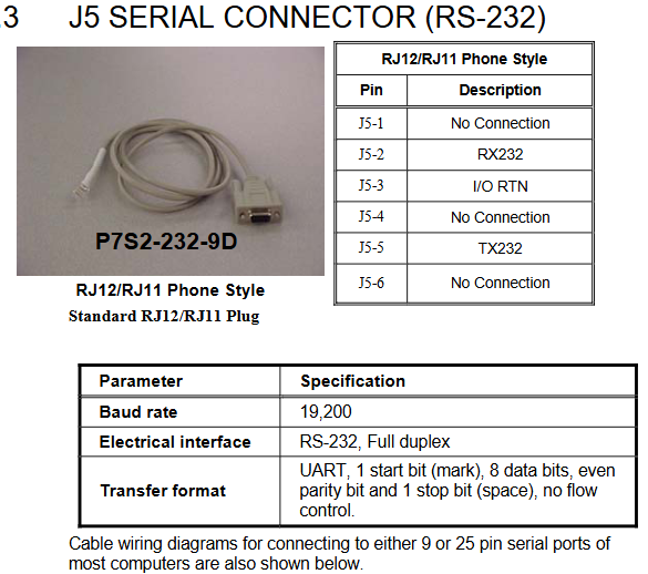
Install P7000Tools (supporting Windows system), connect the PC to the J5 interface of the driver through an RS-232 cable (P7S2-232-9D, RJ12 to 9-pin D-Sub), with a default baud rate of 19200, data bit 8, even parity, and stop bit 1.

After starting the software, scan the drive through “Scan for Connected”. For the first connection, configure the node address (1-99) to ensure that there is no conflict with the hardware switch.

Core configuration module

Motor configuration: Select the motor model (or create a custom motor through the “Motor File Editor”, enter parameters such as rated current, number of poles, peak torque, etc.), execute the “Probe Stepper Motor” to detect the motor inductance, and optimize the control algorithm.

Mechanical parameters: Set user units (steps/revolutions/millimeters/inches), gear ratio (e.g. 2:1 gearbox set to 2 motor revolutions/load revolutions), and load inertia for motion profile calculation.

Command configuration: Set step resolution (consistent with hardware switch), rotation polarity (reverse motor direction), enable polarity (Active Open/Lost), speed/acceleration/deceleration limits. Jog speed is divided into high and low gears (such as 20 revolutions per second for high speed and 0.5 revolutions per second for low speed).

I/O configuration: Customize 9 universal inputs (such as Jog+/Jog -/EOT+/EOT -/fault reset/start movement), input debounce time (default 1 ms), and universal output functions (such as motor operation/stall/EOT latch).

Advanced settings: Adjust anti resonance frequency (formula)

AResFrequency= 100⋅J Rotor ToothCount⋅T max)、 Dynamic smoothing frequency (formula SmoothingFrequency=9 ⋅ J Rotor ToothCount ⋅ T max), current reduction ratio, and delay.

Sports Profile Generation

Supports 63 independent motion profiles, divided into two modes: AVD (acceleration velocity distance) and T/D (time distance), which can set acceleration and deceleration, target speed, motion distance, delay time, and jump index (chain motion).

Select Profile through “Move Select” input (up to 6 channels, binary encoding). If inputting 1+2 triggers Profile 3, configure “Start Move” input to trigger motion (edge triggered).

KOLLMORGEN AKM series synchronous servo motor

Basic Information

Core positioning: The AKM series is a brushless DC synchronous servo motor that uses neodymium iron boron permanent magnet rotors and three-phase stator windings. It is equipped with a hollow shaft rotary transformer feedback as standard, and can be configured with a brake, EnDat encoder, shaft sealing ring, etc. It needs to be combined with a SERVOSTAR servo amplifier to form a closed-loop control system, and direct connection to the mains power is prohibited for operation.

Supporting resources: Should be used in conjunction with SERVOSTAR servo amplifier installation manual, operating software manual, and accessory manual; The original factory provides pre assembled motor power cables (such as 4 × 1mm ² shielded wire) and rotary transformer cables (4 × 2 × 0.25mm ² twisted pair). When selecting, the cable specifications should be matched according to the motor model.

Core technical characteristics and classification of motors

(1) General Technical Parameters

Category parameter item specification

Environmental adaptability to climate category EN 50178 3K3

Operating temperature -5~+40 ℃ (altitude ≤ 1000m), a 6% derating is required for every altitude exceeding 1000m (or a 10K temperature drop offsets the derating)

Protection level: IP65 for the casing, default IP40 for the shaft sleeve (IP65 with shaft sealing ring)

Humidity 95% relative humidity (no condensation)

Electrical characteristics – Insulation class DIN 57530 F

Vibration level DIN ISO 2373 N level

Thermal protection built-in PTC thermistor (155 ℃± 5% action, room temperature resistance ≤ 550 Ω, after action ≥ 1330 Ω)

Mechanical characteristics: Bearing life ≥ 20000 hours (rated condition)

Installation form standard IM B5 (flange installation), supporting orientations such as V1/V3

Shaft end specification: cylindrical shaft (AKM1 with h7 tolerance, others with k6 tolerance), with locking thread, optional keyway (DIN 748)

​(2) Optional configuration

Brake: 24V DC spring compression, braking when power is off, only used for parking braking (frequent operation braking is prohibited). The holding torque of the brake varies for different models (such as AKM2 at 1.42Nm and AKM7 at 53Nm), with a release delay of 20-110ms. When applied, external current components (such as varistors) are required.

Feedback device: Standard 2-pole hollow shaft rotary transformer, optional single/multi turn EnDat encoder (AKM2-4 uses ECN1113/EQN1125, AKM5-7 uses ECN1313/EQN1325) or incremental encoder with commutation signal (Comencoder), the encoder will increase the motor length and cannot be retrofitted.

Shaft sealing ring: anti oil mist/splash, raising the protection level of the shaft sleeve to IP65, not suitable for dry operation scenarios, additional order required.

Keyway: Process the shaft end keyway according to DIN 748, with short keys, and the shaft balance should include the weight of the keys. When selecting, pay attention to the radial force variation (the radial force limit remains unchanged with keyway).

Installation and wiring specifications

(1) Mechanical installation requirements

Installation preparation

Installation surface: It should be made of conductive material (such as aluminum alloy), with a flatness error of ≤ 0.1mm. AKM1/2 should reserve ≥ 50mm of heat dissipation space. AKM3 and above should be matched with designated cold plates (such as AKM3 requiring 350 × 350 × 10mm aluminum plates), and pasted with original thermal conductive film (model 849-373000-04 for small models).

Load limitation: The radial force (FR) allowed at the shaft end is negatively correlated with the rotational speed, for example, at 5000 min ⁻¹, FR=145N for AKM2, and the axial force (FA) ≤ FR/3; The formula for the minimum pulley diameter must be met during belt transmission

D min ≥ M 0/(F R × 2) (M 0 is the static torque) to avoid bearing overload.

Coupling selection: It is recommended to use friction couplings without backlash (such as Baumann&Cie, KTR brand), with a coaxiality error of ≤ 0.1mm. It is prohibited to use rigid couplings with external bearings for constrained installation to prevent excessive stress on the shaft system.

Installation steps

Clean the installation surface, stick the thermal conductive film (if necessary), and use M5 hex screws (torque 0.7~0.8Nm) to fix the motor, ensuring that the flange fits snugly without any gaps.

Install the coupler/pulley and tighten it with the shaft end locking thread. Do not strike the shaft end (to avoid bearing damage). The AKM1 shaft tolerance is h7, and attention should be paid to the fit clearance.

Check the flexibility of the shaft rotation (without jamming or abnormal noise), and ensure that no liquid enters the upper bearing when installing V3 (with the shaft end facing upwards).

(2) Electrical wiring specifications

Wiring sequence and safety

Power off operation, ensure that the servo amplifier capacitor discharges (after power off for ≥ 5 minutes, measure the DC bus voltage<40V), and the motor junction box needs to be reliably grounded (PE wire cross-section>10mm ² or double PE wiring).

The distance between the power cable and the control cable is ≥ 20cm. If the power cable contains a brake control line (such as 4 × 1+2 × 0.75mm ²), it needs to be shielded separately and grounded at both ends.

When the cable length exceeds 25m, Kollmorgen 3YL-20 choke coil is required (such as SERVOSTAR 601-606 with 4 × 1mm ² cable, 620 with 4 × 2.5mm ² cable).

Core interface definition

Power interface: 4+4-pole circular connector (AKM1/2 for straight head, AKM3+for elbow), U/V/W connected to motor three-phase winding, PE connected to motor casing, brake wire (± BR) connected to 24V DC (only for brake models).

Feedback interface: The rotary transformer uses a 12 pole circular connector, with R1/R2 as the reference signal, S1/S2 as the sine signal, S3/S4 as the cosine signal, and COM ± as the power supply; The EnDat encoder uses a 17 pole connector, which includes clock (CLK ±), data (DAT ±), and power supply (+5V/0V).

Typical Connection Diagram 

Rotary transformer motor: The power end U/V/W/PE is connected to the amplifier output, the feedback end R1/R2/S1/S2/S3/S4 is connected to the amplifier rotary transformer interface, and the PTC thermistor is connected in series to the amplifier overheat protection circuit.

Encoder motor: The encoder clock/data line is connected to the amplifier interface and needs to be separately shielded (with both ends of the shielding layer grounded) to avoid parallel wiring with the power cable.

System debugging and maintenance

(1) Debugging process

Pre inspection

Confirm that the motor is matched with the amplifier (rated voltage and current are consistent), the wiring conforms to the diagrams, and the brake can be released normally after being powered on (no jamming at 24V).

Manually rotate the motor shaft, confirm that there is no mechanical blockage, monitor the bearings for any abnormal noise, and check that the heat dissipation channel is unobstructed (ambient temperature ≤ 40 ℃).

Amplifier configuration

Load motor parameters through SERVOSTAR software (Kollmorgen motor automatically recognizes, third-party motors require manual input of rated torque, inductance, etc.), set the resolution and pole number of the rotary/encoder (to match the actual motor, incorrect settings may burn out the motor).

Perform motor recognition and automatic tuning, optimize current loop and speed loop gains, and conduct multi axis linkage testing after single axis debugging is completed.

Functional Verification

Jogging test: Run at low speed (<100min ⁻¹), confirm that the steering and torque output are normal, monitor the motor temperature (≤ 100 ℃ during operation, cool to 40 ℃ after shutdown and touch again).

Brake test: When the power is cut off, the brake should be immediately applied, and the release should be delayed by ≤ 100ms after power on. The vertical axis should be tested for no load drop after power off (with dual protection of mechanical braking).

(2) Maintenance and Lifecycle Management

routine maintenance

Check the bearing noise every 2500 operating hours or annually. If any abnormal noise occurs, stop the machine and replace the bearing (the bearing grease has a lifespan of 20000 hours and needs to be replaced if it exceeds the deadline).

Wipe the outer shell with isopropanol during cleaning (do not soak or spray), and avoid using solvents such as trichloroethylene and nitro diluents (which may damage the RAL 9005 matte black paint coating).

Storage and transportation

Storage conditions: Temperature -25~+55 ℃, humidity 5%~95% (no condensation), original packaging stacking height not exceeding the limit (such as AKM1/2 stacking 10 boxes, AKM6/7 stacking 1 box), storage period unlimited.

Transportation requirements: Climate category 2K3, temperature -25~+70 ℃ (temperature change rate ≤ 20K/hour), avoid impact, and inspect the appearance of the motor for packaging damage (such as no deformation of the shaft end and flange).

Retirement disposal

According to the requirements of the WEEE directive, qualified electronic waste processors can be used for recycling. They can contact service centers in Kollmorgen to obtain recycling channels (such as sending from Europe to Ratingen factory in Germany and from China to Minhang district office in Shanghai).

Troubleshooting

Common fault handling

Possible causes and solutions for the fault phenomenon

The motor does not rotate. The amplifier is not enabled; 2. The set value signal line is broken; 3. The brake is not released; 4. Motor phase sequence error 1. Sending ENABLE signal; 2. Check the continuity of the set value cable; 3. Confirm that the brake is powered by 24V; 4. Swap the U/V phase sequence

Motor runaway motor phase sequence error or amplifier parameter (such as pole pairs) setting error 1. Emergency stop; 2. Correct the phase sequence or amplifier parameters; 3. Re execute motor identification

Amplifier reports’ output stage fault ‘1. Motor cable short circuit/grounding; 2. Motor winding short circuit: 1. Measure the insulation resistance of the cable (≥ 1M Ω); 2. Disassemble the motor and inspect the winding (replace if burned out)

The amplifier reports “motor overheating”. 1. The PTC thermistor is disconnected; 2. Load overload; 3. Poor heat dissipation: 1. Check the PTC wiring; 2. Reduce the load or increase the motor model; 3. Clean the cooling channels and add cooling fans

Brake not braking 1. Brake coil burned out; 2. Axial force overload at the end of the shaft; 3. Insufficient brake torque. 1. Measure the resistance of the brake coil (normally around 6-8 Ω); 2. Check if the axial force is ≤ FR/3 and replace the damaged bearing; 3. Confirm that the brake model matches the motor

Key safety warning

Electrical safety: There may be a high voltage of 900V at the power end of the motor. After power failure, the residual voltage of the capacitor needs to be reduced to the safe value (<40V) within 5 minutes. Before operation, the DC bus voltage must be measured; PE wiring cannot be omitted (leakage current>3.5mA, double PE or large section PE wire to prevent electric shock).

Mechanical safety: The surface temperature of the motor during operation may exceed 100 ℃, and direct touch is prohibited; The keyway at the shaft end needs to be installed with a key before operation to avoid injury caused by centrifugal force throwing out the key; The vertical axis must be equipped with mechanical braking (the holding brake is only used as an auxiliary and requires dual protection in case of malfunction).

Environmental safety: Prohibited from use in explosive or corrosive gas/liquid environments; The motor should be stopped immediately after water ingress, and the insulation resistance (≥ 1M Ω) should be measured after drying before restarting, otherwise it may be short circuited and burned out.

KOLLMORGEN AKD ®- N servo drive

Product Safety and Lifecycle Management

(1) Core safety warnings and compliance requirements

Electrical safety

High voltage risk: The DC bus voltage of the driver can reach up to 900V, and it takes 7 minutes for the residual voltage of the capacitor to drop below 50V after power failure. Before operation, the bus voltage must be measured (AKD-C test X14 terminal, MKD-C test X23 terminal).

Grounding requirements: If the leakage current is greater than 3.5mA, double PE wiring or PE cables with a cross-section greater than 10mm ² should be used, and the installation plate should be made of non painted conductive material to avoid EMC interference.

Electrostatic protection: The equipment contains electrostatic sensitive components inside, and human static electricity must be released before operation to avoid contact with insulating materials (such as synthetic clothing). The equipment should be placed on a conductive surface.

Mechanical safety

High temperature protection: During operation, the temperature of the drive casing may exceed 80 ℃. Before contact, it should be cooled to below 40 ℃ to avoid burns.

Automatic restart risk: When the parameter DRV. ENDEFAULT=1, automatic restart may occur after power on, voltage drop, or power failure recovery. A “Warning: Possible Automatic Startup” sign should be posted in the hazardous area of the machine.

Suspension load protection: An additional mechanical braking device (such as motor brake) should be installed on the vertical axis, and MOTOR.BRAKEIM=1 should be set to ensure that the brake is immediately applied in case of a fault to prevent the load from falling.

Compliance certification: Compliant with the EC Machinery Directive (2006/42/EU), Low Voltage Directive (2014/35/EU), EMC Directive (2014/30/EU), UL/cUL (document number E217428), EAC, RoHS (2011/65/EU), REACH certification, STO function meets IEC 62061 SIL 2, ISO 13849-1 PLd/CAT 3 safety level.

(2) Product Lifecycle Management

Packaging and Shipping

Packaging specifications: Recyclable cardboard packaging is used, with slight differences in size among different models (such as AKD-N00307 packaging size of 120 × 295 × 370mm, weight of 3.2kg), with a maximum stacking height of 8 boxes.

Transportation conditions: temperature -25~+70 ℃ (temperature change rate ≤ 20K/hour), relative humidity ≤ 95% (no condensation), avoid impact, and require personnel with knowledge of electrostatic protection to operate.

Storage and maintenance

Storage conditions: temperature -25~+55 ℃, relative humidity 5%~95% (no condensation), original packaging needs to be retained, maximum stacking height of 8 boxes, recommended storage period not exceeding 2 years (packaging integrity needs to be checked regularly).

Maintenance requirements: No routine maintenance is required, and the wiring tightness and shell integrity should be checked annually by professional personnel; When cleaning, the power should be turned off first, and the outer shell should be wiped with isopropanol (to avoid liquid infiltration into the interior). After cleaning, it should be left to stand for 30 minutes before being powered on.

Retirement and disposal: It needs to be dismantled by electrical professionals and recycled through the designated channel of the original factory according to the requirements of the WEEE Directive (2012/19/EU) (such as being sent from China to Room 302, Building 5, Libao Plaza, No. 88 Shenbin Road, Minhang District, Shanghai). Random disposal is prohibited.

Technical parameters and hardware configuration

(1) Core technical parameters

Category parameter item AKD-N00307 AKD-N00607 AKD-N01207

Mechanical parameter weight (kg) 1.6 2.1 2.1

Dimensions (length x width x height, mm) 201 x 130 x 75 201 x 130 x 75 252 x 130 x 75

Electrical parameters Rated supply voltage (VDC) 560~680 560~680 560~680

Continuous output current (Arms, optimal cooling) 3 6 12

Peak output current (Arms, 5s) 9 18 30

Continuous output power (kW, optimal cooling) 1.3 2.6 5.0

Motor inductance range (mH) 6.3~600 3.2~300 2.5~250

Environmental parameter operating temperature (℃) -10~+40 (4%/K for+40~+55) -10~+40 (4%/K for+40~+55) -10~+40 (4%/K for+40~+55)

Protection level IP65/IP67 (UL Type 4x) IP65/IP67 (UL Type 4x) IP65/IP67 (UL Type 4x)

Vibration level IEC 60721-3-3 Class 3M5 IEC 60721-3-3 Class 3M5 IEC 60721-3-3 Class 3M5

(2) Hardware interface and cable requirements

Core interface definition

Hybrid interface (X1/X2): 7-pin M12 connector, X1 is the “hybrid input” (connected to AKD-C/MKD-C or front stage AKD-N), X2 is the “hybrid output” (connected to rear stage AKD-N), including 3 DC power supplies (± DC-ST, PE) and 4 fieldbus signals (positive and negative), with a maximum current of 18A and a voltage of 850V.

Motor interface (X4): 8-pin M23 connector, transmits motor power (U/V/W/PE), brake signal (± BR), and feedback signal (COM ±) when connected with a hybrid cable; When connected with dual cables, only the motor power and brake signal are transmitted, and the feedback signal is transmitted separately by X5. The maximum current is 15A and the voltage is 630V.

Feedback interface (X5): 17 pin M23 connector (only for DF/DS models), supporting SFD, EnDat 2.1/2.2, BiSS, HIPERFACE and other feedback types, transmitting power (+5V/0V), clock (CLK ±), data (DAT ±) and other signals, with a maximum cable length of 5m.

Digital I/O interface (X3): 8-pin M12 connector, including 3 digital inputs (2 high-speed inputs, update rate 2 μ s); 1 standard input, update rate of 250 μ s), 1 digital output (maximum 30VDC/100mA), DS/DT models additionally include 2 STO status outputs.

Optional interface (X6): 4-pin M12 connector, DF/DG model for three-level fieldbus (transceiver ±), DS/DT model for local STO input (± 24V, current 80mA).

Cable requirements: Kollmorgen original cables must be used, with the following key models:

Hybrid cable: CCNCN1-0250 (3 × 2.5mm ²+4 × 0.25mm ², maximum length 40m) is used from AKD-C to AKD-N, and CCNNN1-0250 (maximum length 25m) is used for AKD-N cascading.

Motor cable: CCJNAz-0150 (4 × 1.5mm ²+2 × 0.75mm ²+2 × 0.34mm ², maximum length 5m) is used for hybrid connection, and CMxNAz-0150 (power)+CFyNAz-0020 (feedback) is used for dual cable connection.

STO cable: Phoenix SAC 4P-M12MS (4 × 0.34mm ², maximum length 30m) is used for DS/DT models.

Installation and commissioning process

(1) Mechanical installation

Installation preparation: Ensure that the installation surface is made of conductive material (such as aluminum cold plate), and the size of the cold plate needs to meet the requirements (AKD-N00307 needs 350 × 350 × 10mm, AKD-N01207 needs 480 × 400 × 84mm finned heat sink). The surface flatness error should be ≤ 0.1mm, and a thermal conductive film (model 849-373000-04 for 003/006 model, 849-374001-04 for 012 model) needs to be pasted.

Installation steps:

Fix the driver on the cold plate with 4 M5 hex screws (torque 0.7~0.8Nm), ensuring that there is a heat dissipation space of ≥ 50mm around.

If using the optional heat sink (50mm high), four M4 × 16 screws (torque 0.2~0.25Nm) are needed to secure the heat sink to the bottom of the drive.

Check the installation firmness to avoid loose wiring caused by vibration.

(2) Electrical wiring

Wiring sequence: It is recommended to follow the sequence of “X2 (mixed output) → X1 (mixed input) → X4 (motor) → X5 (feedback) → X3 (I/O) → X6 (optional)” to avoid live operation.

Key wiring specifications:

Power and grounding: PE wires need to be double connected or cables with a cross-sectional area greater than 10mm ² should be used. The cold plate should be reliably connected to the system grounding grid (impedance ≤ 0.1 Ω).

Motor wiring: The U/V/W phase sequence should be consistent with the motor nameplate, and the polarity of the brake wire (± BR) should be confirmed (reverse connection can cause brake failure). The shielding layer of the mixed cable should be grounded through a plug.

Feedback wiring: EnDat/BiSS feedback needs to distinguish between clock and data lines to avoid reverse wiring; The DF/DS model with single cable connection needs to plug AKD-N-JUMP-X5 connector (short circuit Pin4/Pin5) into X5 to ensure feedback power supply.

STO wiring: The local STO input needs to be connected to a PELV level 24V power supply (such as a safety controller output), and the cable needs to be wired separately, away from power cables, to avoid interference.

System topology limitations:

AKD-C single string can connect up to 8 AKD-Ns, MKD-C single string can connect up to 14 (hardware revision C), and the total cable length of a single string is ≤ 100m.

Single string total current: AKD-C two string total ≤ 17A, MKD-C single string ≤ 16A; total power: AKD-C two string total ≤ 11kW, MKD-C single string ≤ 10kW, axis coincidence coefficient needs to be calculated to avoid overload.

(3) System debugging

Preliminary preparation:

Install the WorkBench software (downloaded from DVD or official website) and connect the X18 interface between the PC and AKD-C/MKD-C using an Ethernet cable.

Connect the 24V logic power supply of the system (no main power supply required), confirm that the Ethernet indicator light of AKD-C/MKD-C is on, and that the PC can recognize the driver (distinguished by MAC address or name).

Basic configuration (via Setup Wizard):

Select the driver and configure the IP address (default associated with CAN node address, can be manually modified).

Select the motor model (Kollmorgen motor automatically loads parameters, third-party motors require manual input of rated current, inductance, and other parameters).

Configure feedback type (such as EnDat 2.2), set gear ratio (6091h) and feed in constant (6092h).

Perform motor identification and automatic tuning, optimize current loop and speed loop parameters.

Security function testing:

Global STO test: Send an STO signal through the X16 terminal of AKD-C/MKD-C to confirm that the driver torque is cut off and the motor slides freely.

Local STO test (DS/DT models): Disconnect the STO enable signal (0V) of X6 to confirm that the driver cannot be enabled; After restoring 24V, the driver can start normally.

Functional verification:

Enable the driver (hardware enabled+software enabled), send jog commands through WorkBench, and confirm that the motor direction and speed meet expectations.

Test digital I/O: Set DI1 to “controlled stop” and trigger the motor to stop at the set deceleration (CS. DEC); Check if the output status of DO1 is consistent with the preset function.

Monitoring key parameters: Check the DC bus voltage (VBUS. VALUE), motor current (IL. FB), and temperature (DRV. TEMP) to confirm that there are no abnormal warnings or faults.

Detailed explanation of Safety Functions (STO)

(1) STO types and applicable scenarios

Global STO: Control the STO function of the entire string through AKD-C/MKD-C, suitable for multi axis synchronous safety control, supports 1-14 AKD-N (hardware revision C), response time ≤ 10ms (the more nodes, the faster the response), requires the use of original factory mixed cables, and is prohibited from accessing DS/DT models (not subject to global STO control).

Local STO (DS/DT models only): Independently controls a single driver through the X6 interface, suitable for single axis safety requirements (such as door control interlocking), requires external PELV level 24V power supply, response time ≤ 10ms, STO status output through X3 (for information feedback only, not for safety interlocking).

(2) STO security features

STO Structure ISO 13849-1 IEC 62061 MTTFd (year) PFH (1/h) SFF (%)

AKD-C+1 × AKD-N (global) PLd/CAT3 SIL2 ≥ 100 2.99E-08 97.08

MKD-C+14 × AKD-N (global) PLd/CAT3 SIL2 ≥ 100 1.86E-08 94.20

1 × AKD-N-DS/DT (local) PLd/CAT3 SIL2 ≥ 100 2.90E-08 97.12

(3) Usage restrictions

Prohibited for use in elevator drives, ship/marine environments, explosive environments, and corrosive/conductive dust environments.

STO only cuts off the motor torque and does not provide electrical isolation. During maintenance, it is necessary to disconnect the main power supply and wait for the capacitor to discharge.

An additional mechanical brake is required for the vertical axis, and the motor must be reduced to zero speed and the driver disabled before STO activation.

AKD ®  Servo driver CANopen communication

CANopen Communication Fundamentals and Hardware Configuration

(1) CAN Bus hardware interface and settings

Interface definition: Two 6-pin RJ-12 terminals, X12 (CAN input) and X13 (CAN output), are used, with clear pin functions. Pin3 is CANH, Pin4 is CANL, Pin2 is shielding layer, Pin5 is GND, and Pin1 and Pin6 are used to activate the built-in 132 Ω terminal resistor (only devices at both ends of the bus need to be enabled).

Key parameter configuration

Baud rate: Supports fixed baud rates of 125/250/500/1000 kBit/s and automatic detection mode, set through parameter FBUS.PARAM01 or the driver front panel rotary switch (S1=9, S2 corresponds to 0-4). The automatic detection mode requires the driver to listen to valid CAN frames on the bus and match the bit time.

Node address: Set by the S1 (MSB) and S2 (LSB) rotary switches on the front panel of the driver, with an address range of 1-127, and associated with the IP address (such as S1=4, S2=5 corresponding to CAN address 45, IP address 192.168.0.45), which can be separated from the rotary switch configuration through WorkBench.

Terminal resistor: The AKD at both ends of the bus needs to activate the built-in terminal resistor, which can be short circuited to X13 terminals Pin1 and Pin6 using an optional terminal plug (P-AKD-CAN-TERM). Non terminal devices need to disconnect the terminal resistor to avoid signal reflection.

Cable requirements: Shielded twisted pair cables with characteristic impedance of 100-120 Ω must be used, and the maximum cable length varies with the baud rate (10m at 1000 kBit/s, 70m at 500 kBit/s, 115m at 250 kBit/s). The cable capacitance must be ≤ 60 nF/km, the lead loop resistance must be ≤ 159.8 Ω/km, and the shielding layer must be reliably grounded to ensure EMC performance.

(2) CANopen core communication protocol

Communication Object (COB): CANopen communication is based on an 11 bit COB-ID to identify the communication object, with priority determined by the ID. The core objects include:

Network Management Object (NMT): COB-ID=0, used for node start/stop, communication reset (such as resetting nodes with cs=129, starting nodes with cs=1).

Synchronization Object (SYNC): The default COB-ID is 0x80, providing a periodic clock for the bus and supporting multi axis synchronous motion. COB-ID can be modified through object 1005h, and the communication cycle period (in μ s) can be defined through object 1006h.

Emergency Object (EMCY): High priority event trigger object, COB-ID=0x80+node address, containing 2-byte error code, 1-byte error register, and 1-byte error category, used to report drive failures (such as overvoltage and overcurrent).

Service Data Object (SDO): Used to access object dictionaries, supports parameter reading and writing (such as downloading motor parameters and reading fault history through SDO), uses acknowledgment communication, and includes protocols such as initiating download/upload, segment transfer, and terminating transfer.

Process Data Object (PDO): used for real-time data interaction, divided into receiving PDO (RXPDO, master station → driver, such as control word, target speed) and transmitting PDO (TXPDO, driver → master station, such as status word, actual position), supporting three transmission methods: event triggered, time triggered, and synchronous triggered.

Data types: Define unsigned integers (UNSIGNED8/16/32, etc.), signed integers (INTEGER 8/16/32, etc.), mixed data types (STRUCT/ARRAY), and extended data types (OCTET_STRING/VIIBLE_STRING), with transmission using “low order first” (Intel format) to ensure multi device data compatibility.

Object Dictionary and Core Function Configuration

(1) Object Dictionary Classification and Key Objects

The object dictionary is the core of CANopen communication, which is divided into DS301 standard objects (1000h-1FFFh), manufacturer specific objects (2000h-3FFFh), and DS402 driver sub protocol objects (6000h-6FFFh) according to their functions. The key objects are as follows:

DS301 standard object

1000h (device type): Identify the device as a servo drive (DS402 sub protocol), default value 0x00020192, read-only.

1001h (Error Register): A 1-byte register, where bit 0 represents a general error, bit 1 represents a current error, bit 2 represents a voltage error, and bit 3 represents a temperature error, used to quickly locate the type of fault.

1003h (predefined error field): Array type, stores the last 10 emergency error records, Subindex 0 represents the number of errors, Subindex 1-10 stores specific error codes.

1400h-1403h (RXPDO communication parameters): Define the COB-ID (default 0x200+node address, etc.) and transmission type (such as 0xFF for event triggering) of RXPDO.

1600h-1603h (RXPDO mapping parameters): Configure RXPDO data content, default RXPDO1 mapping control word (6040h), customizable mapping target position (607Ah), target velocity (60FFh), etc.

1800h-1803h (TXPDO communication parameters): Define the COB-ID of TXPDO (default 0x180+node address, etc.), disable time (to avoid bus overload), and event timer.

1A00h-1A03h (TXPDO mapping parameters): Configure TXPDO data content, default TXPDO1 mapping status word (6041h), customizable mapping actual position (6064h), actual speed (606Ch), etc.

DS402 driver sub protocol object

6040h (control word): 16 bit control word, bit 0 controls “on/off”, bit 2 controls “quick stop”, bit 3 controls “operation enable”, bit 7 controls “fault reset”, used to drive state machine switching.

6041h (Status Word): A 16 bit status word, with bit 0 indicating “ready to start”, bit 1 indicating “on”, bit 2 indicating “operation enabled”, and bit 3 indicating “fault”, used to provide feedback on the current status of the driver.

6060h (Operation Mode): Set the driver operation mode, supporting trajectory position mode (01h), trajectory speed mode (03h), trajectory torque mode (04h), zero calibration mode (06h), interpolation position mode (07h), etc., and switch modes when the motor is at zero speed.

607Ah (target position): a 32-bit integer, the target position setting value in trajectory position mode, supports absolute/relative position control, and the unit is defined by the gear ratio (6091h) and feed in constant (6092h).

6064h (actual position value): 32-bit integer, feedback driver actual position, resolution can be adjusted through object 608Fh (position encoder resolution).

6098h (zeroing method): an 8-bit integer, defining the zeroing method (such as -7 for negative direction zeroing input and feedback zeroing, 8 for positive direction reference switch zeroing), which needs to be used in conjunction with zeroing velocity (6099h) and zeroing acceleration (609Ah).

Manufacturer specific object

2001h (System Fault): Array type, storing the last 10 system fault numbers, Subindex 1-10 corresponds to DRV.FAULTRA1-DRV.FAULTRA10, read-only.

2011h (DRV. RUNTIME): A 32-bit unsigned integer that records drive runtime in seconds and is read-only.

20A4h (Latch Control Register): A 16 bit register that controls the monitoring enable of the latch (such as bit 0 enabling the rising edge of external latch 1) and supports position capture function.

345Ah (brake control): array type, Subindex 1 controls the brake command (0=hold brake, 1=release), Subindex 2 provides feedback on the brake status, supports direct control of the brake via fieldbus, and it should be noted that in case of a fault, the driver will take over the brake logic again.

(2) Example of Core Function Configuration

PDO configuration: Taking “controlling motor speed through PDO” as an example, it is necessary to first disable unused PDO to reduce bus load, then configure RXPDO to map target speed (60FFh), TXPDO to map actual speed (606Ch), and finally enable PDO and set synchronous triggering mode (such as transmitting PDO once every SYNC message received).

Zeroing configuration: Write the zeroing method (6098h=-7), zeroing speed (6099h Sub1=10000 counts/s), zeroing acceleration (609Ah=1000 counts/s ²) through SDO, and then trigger the zeroing operation through the control word (6040h). After zeroing is completed, set the status word (6041h) bit 12 to 1 to indicate successful zeroing.

Trajectory position control: Set the operation mode to Trajectory position mode (6060h=01h), write the target position (607Ah), trajectory velocity (6081h), and trajectory acceleration (6083h) through RXPDO, trigger control word bit 4 to start motion, and TXPDO provides real-time feedback on the actual position (6064h) and motion status.

Fault handling and emergency messages

(1) Emergency error codes and fault classification

The manual provides a detailed list of error codes corresponding to CANopen emergency messages, covering categories such as hardware failures, power failures, motor/feedback failures, communication failures, etc. Typical codes are as follows:

Error code, fault type description, remedial measures

0x3210 Power failure F501 DC bus overvoltage reduces load deceleration rate, check regeneration resistor connection

0x3220 power failure F502 DC bus undervoltage check input power stability, troubleshooting loose wiring

0x4310 Temperature Fault F235 Drive Heat Sink Overheats, Clean Heat Dissipation Channel, Check Fan Operation Status, Reduce Load

0x7380 Feedback Fault F402 Feedback 1 Analog Signal Amplitude Fault Check Feedback Cable Wiring, Replace Feedback Equipment

0x8480 Motor Fault F302 Motor Overspeed Increase Speed Threshold (VL.THRESH), Optimize Speed Loop Parameters

0xFF02 current fault F529 exceeds Iu current offset limit check current sensor, recalibrate current loop

(2) Troubleshooting process

Identify fault codes: Obtain error codes by reading the DRV.FAULTRAS command through the driver panel (dual 7-segment screen displaying “F+code”, such as F501), LED indicator light (red flashing=fault), or WorkBench software.

Identify the cause of the fault: According to the “CANopen Emergency Messages and Error Codes” section of the manual, match the fault type corresponding to the code (such as power supply, feedback, temperature), and investigate the hardware wiring, parameter configuration, and environmental conditions (such as temperature and load).

Implement remedial measures:

Wiring faults (such as feedback disconnection): After power failure, unplug the cable and confirm the pin correspondence (refer to the attached wiring diagram).

Parameter type faults (such as bus overvoltage): Adjust parameters through SDO (such as reducing deceleration rate), save and restart the drive.

Hardware faults (such as power level faults): If restarting is ineffective, contact technical support to return to the factory for repair.

Clear fault: Clear the fault by controlling bit 7 (fault reset) or DRV.CLRFAULTS command, confirm that the fault is eliminated, and then re enable the drive.

AKD ®  Servo drive fault card

Basic Information

Scope of application: This fault card is applicable to Kollmorgen AKD series servo drives (hardware revision E), covering standard and AKD-T models (supporting BASIC program function). It provides a detailed list of fault/warning codes, causes, remedies, and drive responses, and is the core reference document for troubleshooting.

Version iteration: The document has undergone 13 revisions (A-M version), with the latest M version (November 2020) updating code descriptions such as F470 (feedback 3 fault) and F583/n583 (Hall effect sorting error). Historical versions have added key fault entries such as F314 (motor phase loss), F587 (full AC input phase loss), and F634 (failure of regenerator test).

Supporting tools: Fault information can be viewed through the driver panel display (single/dual 7-segment screen), LED indicator lights (screenless models), or WorkBench software. It supports reading the fault list through the DRV.FAULTRAS/DRV.Warning commands, which can be called by external controllers/HMIs to obtain information.

Basic explanation of faults and warnings

(1) Indicator type and display rules

Equipment configuration fault/warning indication display logic

The left side of the dual 7-segment display shows “F” (fault) or “n” (warning), and the right side displays a 3-digit code (such as F101, n107) to prioritize the highest priority fault. When there are multiple faults, they are displayed in turn

Single 7-segment display flashes in the order of “F/n+code” (such as “F” first, then “1”, “0”, “1”), following the same dual screen logic. The complete code needs to be identified through the flashing sequence

Only the LED indicator light flashing red indicates a fault, while flashing yellow indicates a warning. WorkBench needs to be connected to view the specific code

(2) Drive fault response type

Controlled shutdown: Slow down the motion to zero speed (parameter CS.VTHRESH/CS-TO defines threshold), then disable the power level, suitable for non emergency faults (such as F121 zero error, F438 position following error).

Immediately disable power level (coasting stop): Cut off the motor power directly and allow the motor to coast freely to a stop, suitable for hardware failures (such as F101 firmware incompatibility, F201 built-in RAM damage).

Dynamic braking: By short circuiting the motor phase to slow down the load, it is suitable for dangerous faults (such as F302 overspeed, F404 illegal Hall state), and attention should be paid to the mechanical stress during the braking process.

Extended response (AKD-C central power supply): In addition to the driver’s own response, it will also disconnect the power fault relay, remove the global enable signal, and even cut off the logical voltage of the device string (such as F545 device string overcurrent).

Core fault classification and typical codes

(1) Hardware and firmware failures (F100-F299)

1. Firmware and FPGA related

F101 (firmware incompatible): The installed firmware does not match the hardware of the drive, and compatible firmware needs to be loaded (e.g. UCB1V2 label model requires firmware ≥ 4.0.0).

F103/F104 (FPGA damage): The resident/running FPGA detects a software malfunction, and restarting is ineffective. Technical support should be contacted, and it may be necessary to return to the factory for repair.

N101/n102 (FPGA version exception): The laboratory version FPGA or minor version does not match the firmware, and an official compatible FPGA version must be loaded.

2. Memory and hardware failures

F105/F106 (NV memory error): Non volatile memory flag/data corruption, reset default parameters through WorkBench loading, F106 is normal after firmware download (fault needs to be cleared and parameters saved).

F201-F203 (RAM/code integrity failure): Internal/external RAM is damaged or FPGA register access is incorrect, restarting is ineffective and the driver needs to be replaced.

F234-F243 (temperature sensor malfunction): The sensor is at ultra-high temperature (F-level) or ultra-low temperature (F-level). Check the ventilation of the cabinet and clean the heat dissipation channel.

(2) Motor and feedback faults (F300-F499)

1. Motor related

F301/n301 (motor overheating): The motor temperature exceeds the threshold. Check the ambient temperature, radiator installation, reduce load or optimize the motion curve.

F302 (overspeed): If the motor speed exceeds VL.THRESH, it is necessary to increase the threshold or decrease the speed command, and dynamic braking will be triggered in emergency situations.

F304/n304 (motor current feedback): Exceeding the maximum motor power, check if the load is stuck and if the current limit is correct, and optimize the motion configuration by reducing acceleration.

F314 (motor phase loss): The motor phase wire is not connected correctly. Check the AKD motor connector wiring (if the U/V/W phase is loose), disable the power level, and repair it.

2. Feedback related

F401 (Invalid Feedback Type): Feedback type not connected or selected incorrectly. Check the wiring of the main feedback (X10 interface) and confirm that the feedback type (such as EnDat, BiSS, rotary transformer) is consistent with the parameter configuration.

F404 (Illegal Hall State): The Hall sensor returns 111/000 (the legal state is 001/010/011/100/101), check if the Hall wiring is broken or has poor contact, and trigger dynamic braking protection.

F438/n438 (position following error): The actual position exceeds the maximum allowable deviation. Check if the load has increased, if the feedback commutation setting is correct, and adjust the servo gain or position deviation threshold.

F470 (Feedback 3 Fault): The third level feedback (X9 interface) is not connected or communication is abnormal. Check FB3.FAULTRA for detailed information, repair the wiring or replace the feedback device.

(3) Power supply and power level faults (F500-F599)

1. Bus voltage related

F501/n501 (Bus Overvoltage): The bus voltage exceeds the threshold, often due to high regenerative energy of the load. It is necessary to reduce the load, optimize the deceleration curve, or increase the regenerative resistance capacity.

F502 (bus undervoltage): If the bus voltage is below the threshold, check if the input power supply is stable, check if the power supply wiring is loose or if there is a power supply fault, and trigger a controlled shutdown.

F503 (Bus capacitor overload): Connect the three-phase driver to a single-phase input or ultra single-phase load, confirm the power phase wiring (L1/L2/L3), and replace the matching power supply.

2. Power level and regeneration faults

F519 (short circuit in regeneration circuit): The regeneration resistor or IGBT is short circuited. It is necessary to disconnect the power supply and check the resistance wiring. Contact technical support to replace the power components.

F521/n521 (regeneration circuit over power): The power of the regeneration resistor is insufficient. Replace it with a larger capacity resistor or enable DC bus sharing, and disable power level protection equipment.

F525 (output overcurrent): If the current exceeds the peak value of the driver, check if the motor is short circuited and if there is a feedback fault. Urgently disable the power level to prevent hardware damage.

F531 (power level fault): Power level hardware fault, restart is ineffective and the driver needs to be replaced, which is a fatal fault.

(4) Fieldbus and communication failure (F600-F799)

F602 (Safety Torque Off, STO): Trigger the STO function, confirm safety conditions, and then power on again, in accordance with functional safety specifications (such as EN ISO 13849).

F702/n702 (fieldbus communication disconnected): All fieldbus communication is lost. Check the X11 interface wiring (such as EtherCAT, CANopen), host settings, and trigger controlled shutdown.

F706/n706 (fieldbus set point loss): The host stops sending set points due to timeout. Check the stability of the bus connection, reduce the bus load, or adjust the timeout parameter.

(5) AKD-T exclusive fault (F800-F999)

AKD-T supports running BASIC programs, and many faults are related to program execution. The typical code is as follows:

F801 (divided by zero): There is a division by zero operation in the program, modify the code to avoid invalid calculations.

F802 (Stack Overflow): Insufficient program stack memory, optimize code structure, reduce nested calls.

F824/F825 (mode incompatible): DRV.OPMODE needs to be set to 2 (position mode), DRV.CMDSOURCE needs to be set to 5 (program command), adjust the parameters and restart the program.

F901 (Too Many Cams): The number of cams defined in the program exceeds the upper limit, reduce cam configuration or optimize motion logic.

Key fault troubleshooting process

Identification code: Obtain the fault code through panel display or WorkBench, confirm the code type (F/n) and priority.

Identify the cause: Based on the corresponding entries on the fault card, investigate the hardware wiring (such as feedback, power supply, motor phase lines), parameter configuration (such as feedback type, current limit), and environmental conditions (temperature, ventilation).

Execute remedial measures:

Wiring faults (such as F314 motor phase loss, F404 Hall wire breakage): Repair the wiring after power failure, and confirm the correctness of the connection before re enabling.

Parameter faults (such as F105 NV memory error, F501 bus overvoltage): Reset parameters or adjust thresholds through WorkBench, save and restart the drive.

Hardware failures (such as F201 RAM damage, F531 power level failure): If restarting is ineffective, please contact technical support and return to the factory for repair if necessary.

Clear the fault: Use the DRV.CLRFAULTS command or WorkBench button to clear the fault, confirm that the fault is eliminated, and then re enable the drive.

SERVOSTAR ®  CD series servo amplifier

Basic Information

Product positioning: SERVOSTAR ®  The CD series is an industrial grade servo amplifier launched by Danaher Motion, covering three models: Cx03 (3A continuous), Cx06 (6A continuous), and Cx10 (10A continuous), suitable for high-precision motor control scenarios. It has passed UL/cUL 508C certification (US and Canadian markets) and CE certification (EU market), and needs to be integrated into industrial equipment for use.

Core support: The document comes with a CD-ROM, which includes a technical manual (in PDF format), MOTIONLINK debugging software, and Adobe Acrobat Reader installation program; Hardware needs to be equipped with motors, feedback devices (encoders/rotary transformers), optional regenerative resistors (ERH-26), and EMI filters (such as Corcom F7202A, Schaffner FN258 series).

Version Description: The document version is M-SS-017-07 Rev C. The Series 5 (Version 2) model is not compatible with the PA-LM bus module, and some features (such as extended I/O interface C9) are only supported by Series 5; The firmware needs to be version 4.0.0 or higher (UCB1V2 label model), and it must be paired with a compatible version of IGNITE upgrade tool.

Safety and compliance requirements

(1) Personnel qualifications and operating standards

Qualification requirements: Only professionals with experience in motor installation and commissioning are allowed to operate, and they must be familiar with standards such as IEC 364/CENELEC HD 384, DIN VDE 0100, and national safety regulations.

Core Warning:

Risk of electric shock: During equipment operation, there is a 230VAC input and a 430VDC bus voltage. After power failure, there is residual dangerous voltage in the capacitor. It is necessary to wait for at least 10 minutes and measure the voltage (<50V) before operation; Reliable grounding is necessary (low impedance grounding, otherwise personal safety cannot be guaranteed).

Electrostatic protection: Contains electrostatic sensitive components. Before operation, it is necessary to release human static electricity and avoid contact with high insulation materials (such as chemical fibers and plastic films). The equipment should be placed on a conductive surface.

High temperature and mechanical risks: During operation, the temperature of the heat sink can reach 80 ℃ (176 ° F) to avoid burns; The start-up process may cause the motor to rotate, and it is necessary to ensure that there are no personnel/obstacles in the hazardous area.

(2) Compliance standards

Key standards applicable to certification/instruction scope

UL/cUL 508C specifies design requirements for power filtering, grounding, insulation, etc. to prevent fires, electric shock, and personal injury in the US and Canadian markets

CE certification EU market EMC directive (89/336/EEC): compliant with EN 55011 (radiated/conducted emissions), EN 61000-4 series (immunity); Low Voltage Directive (73/23/EEC): Complies with EN 50178, EN 60204

Global mechanical safety requires equipment to comply with EN 60204 (Mechanical Electrical Equipment) and EN 292 (Mechanical Safety), and equipment manufacturers need to complete risk assessments

Installation and wiring

(1) Mechanical installation

Installation requirements: Vertically fixed to the conductive grounding backplate (metal contact ensures EMC performance), with reserved heat dissipation space around (left-right spacing ≥ 12.7mm, up-down spacing ≥ 63.5mm); Secure with M4 (or 10-32) screws, torque 20 lb in (2.26 Nm).

Dimensions and Weight: Cx03 measures 67.3 × 163 × 244mm (width × height × depth) and weighs 1.61kg; Cx06 measures 83.3 × 163 × 244mm and weighs 2.22kg; Cx10 measures 99.1 × 163 × 256mm and weighs 2.69kg.

(2) Electrical wiring

Grounding and bonding:

Safe grounding: All components (amplifiers, filters, motors) need to be connected to a “star shaped grounding point”. It is recommended to use copper bars or flat braided wires (to reduce high-frequency impedance) to avoid relying on a single wire (inductance 8nH/inch, which affects the filtering effect).

Shielding bonding: The shielding layer of the motor line and feedback line should be exposed near the amplifier and connected to the backplane through metal clamps (such as Phoenix Contact products); If metal conduits are not used for power supply incoming lines, shielded cables must be used and reliably bonded.

Key interface wiring:

Power input: 115/230VAC (± 10%), single/three-phase optional (Cx0x200 only single-phase), wire diameter 14-12AWG (2.5-4mm ²), external fuse required (10AT for Cx03, 15AT for Cx06, 22-27AT for Cx10).

Motor and Feedback: The length of the motor wire (14AWG/2.5mm ²) is recommended to be ≤ 25m. The feedback wire (encoder/rotary transformer) needs to be shielded with twisted pair. The C2 interface (feedback) pin corresponds to different functions of the resolver/encoder/sine encoder (such as the resolver sine signal connected to Pin1-2, and the encoder A/B phase connected to Pin1-2/4-5).

The control I/O: C3 interface includes ± 10V differential analog input (Pin2-3), 24V remote enable (Pin7-8), fault relay output (Pin5-6, 1A/24VDC) and analog output (Pin13, monitoring speed/current, ± 10V/12 bit resolution), wire diameter 18-22AWG (0.3-0.75mm ²), and it is recommended to use cold pressed terminals.

EMI filtering:

Input filtering: EMI filters (such as Cx03 with Corcom F7202A and Cx10 with Schaffner FN258-16/07) need to be installed at the power input end. The filters should be installed tightly against the input end (distance ≤ 30cm, and over distance should be connected with flat braided wire), and the shell should be in contact with the backplate metal (remove oil paint).

Motor filtering: Not mandatory, but it is recommended to add filtering for long motor wires (>25m) or non-metallic cabinets to reduce differential mode noise coupling.

Hardware specifications and electrical parameters

(1) Core electrical parameters

Parameter Cx03 Cx06 Cx10

Continuous output current (RMS) 3A 6A 10A

Peak output current (500ms/RMS) 9A 18A 20A

Input voltage 110-230VAC (± 10%), single-phase/three-phase (Cx0x200 only single-phase) 230VAC (± 10%), three-phase 230VAC (± 10%), three-phase

Bus voltage 325VDC (nominal), overvoltage protection 430VDC, undervoltage protection 90VAC

PWM frequency 16kHz (current loop update rate 62.5 μ s) 8kHz (current loop update rate 62.5 μ s) 8kHz (current loop update rate 62.5 μ s)

Environmental temperature operation: 5-45 ℃ (41-113 ° F), storage: 0-70 ℃ (32-158 ° F)

Cooling power consumption 60W, 80W, 132W

(2) Interface definition

Communication interface C1: Supports RS232 (Pin2=RXD, Pin3=TXD) and RS485 (Pin6=TXD+, Pin7=TXD -, Pin8=RXD+, Pin9=RXD -), used for PC debugging or multi machine networking (MultiDrop address is set by DIP switches 1-5, optional 0-31).

Feedback interface C2 (25 pins):

Resolve: Pin1-2 (sine signal), Pin4-5 (cosine signal), Pin15-16 (reference signal);

Encoder:Pin1-2(A/A)、Pin4-5(B/B)、Pin15-16(Index/Index)、Pin22-24( Hall signals H1A/H2A/H3A); Sine Encoder:Pin1-2(A/A)、Pin4-5(B/B)、Pin9-10(Data/Clock), Requires 5V power supply (Pin18-20).

Expansion interfaces: C4 (equivalent output of encoder, RS485 differential), C8 (remote encoder input), C9 (only Series 5, 3-channel input/2-channel output), C7 (RS232 multi machine communication, CK100 kit required).

DIP switch (10 bits): Switch 1-5 sets MultiDrop address, switch 6 sets baud rate (0=9600/2M, 1=19200/4M), switch 7 sets position hold (1=active), switch 8 sets driver enable (1=disabled), switch 9 sets SERCOS transmit power (1=high power).

Control performance and functionality

(1) Control loop characteristics

Key parameters of control loop update rate and bandwidth

Current loop 62.5 μ s (16kHz)<2000Hz fully digital pole configuration, supports adaptive gain, monitors A/C phase current (IA/IC), with I ² t turn back protection (to prevent driver overheating)

Reversing ring 62.5 μ s (16kHz) – sine wave commutation, supports “torque angle lead” technology, maximum commutation frequency 400Hz, needs to be aligned with the back electromotive force of the motor

Speed loop 250 μ s (4kHz)<400Hz PDFF (pseudo differential feedforward) algorithm, speed resolution 1RPM or VLIM/16384, long-term speed stability 0.01%

Position ring 500 μ s (2kHz) – supports hardware limit (C3 interface IN1/IN2), software limit (PMAX/PMIN), position deviation monitoring (PE>PEMAX triggering fault)

(2) Core functions

Feedback support: Compatible with incremental encoders (A/B/Z+Hall), rotary transformers (single/multi speed), sine encoders (EnDat/HIPERFACE), supports encoder equivalent output (C4 interface, up to 3MHz frequency, scalable resolution).

Protection mechanism: Over temperature (trip at 80 ℃), overvoltage (430VDC), undervoltage (90VDC), overcurrent (power level surge), feedback disconnection (A/B phase/rotary transformer disconnection), motor overheating (thermal monitoring, PTC>12.4k Ω or NTC<0.5k Ω triggering fault).

Regeneration control: Built in braking circuit, activated when the bus voltage reaches 390VDC, external regeneration resistor (ERH-26) can handle excess energy, Cx03 has a minimum resistance of 20 Ω and a maximum power of 200W.

Debugging and troubleshooting

(1) Debugging process

Software installation: Install MOTIONLINK from the CD-ROM or official website (www.danahermotion. com), which supports Windows 95/98/NT 4.0/2000 systems and requires configuration of a serial port (COM1-COM4, baud rate matching DIP switch).

Quick Startup Wizard:

Motor configuration: Select the motor model (such as GOLDLINE series) from the database, click “To Drive” to download parameters. For unknown motors, manually enter parameters such as MBEMF (back electromotive force) and MENCRES (feedback resolution).

Feedback configuration: Select the feedback type (encoder/rotary transformer), confirm the C2 interface wiring, and the rotary transformer needs to perform a zeroing program.

Enable and Test: Connect the 24V enable power supply (C3 Pin7-8), and the software executes the “EN” command to enable the driver. Test the motor rotation through the “Jog” mode and monitor the speed/current (MOTIONLINK monitoring interface).

Firmware upgrade: Series 5 models do not support it. For older models, DIP switch 8/10 needs to be set to 1, enter Ember mode, load the firmware (Lccd_ xxx. emb) using IGNITE tool, and restore the switch to 0 after upgrading.

(2) Troubleshooting

Fatal malfunction (requiring power outage/enable reset):

Overheating (t): Check if the cooling fan and load are overloaded, reset after cooling;

Overvoltage (o): Reduce deceleration rate and check the connection of the regeneration resistor;

Overcurrent (P): Check for motor short circuit and power level fault, and power off reset is required;

Feedback fault (r0-r13): Check for broken feedback cables (such as r1=rotary transformer broken, r4=encoder A/B broken), reconnect and reset.

Non fatal malfunction (enable reset):

Undervoltage (u): Check the input voltage and eliminate power supply faults;

Motor overheating (H): Cool the motor and check the thermostat wiring (C2 Pin13/25);

Overspeed (J/J1): Adjust VOSPD (overspeed threshold) or VLIM (speed limit) to optimize the tuning parameters of the speed loop.

No message fault (only displayed in the status bar):

Limit trigger (L1/L2/L3): Hardware limit switch open circuit (C3 IN1/IN2), check mechanical limit or wiring;

Memory failure (I/c): RAM/EPROM test failed, hardware replacement is required;

Watchdog (≡): Software malfunction, contact manufacturer technical support.

SERVOSTAR ®  CD-LITE servo amplifier

Basic information of the document

Product positioning: SERVOSTAR ®  CD-LITE is an economical digital servo amplifier launched by Danaher Motion Kollmorgen. It focuses on current loop applications, supports full digital current and speed loop control, does not require potentiometer adjustment, and has digital parameter storage without drift. It is compatible with various brushless motors.

Version compatibility: The document has been revised to version 2 of 2003, corresponding to firmware version 1.1.0, and needs to be paired with MOTIONLINK 4.4.3 software (the two must match the version and cannot be mixed); Historical versions include version 1 from 2001 (firmware 0.1.2).

Core identification: The product model includes current level (03=3A continuous/9A peak, 06=6A continuous/18A peak, 09=10A continuous/20A peak), logic power mode (250=line generation, 260=external 24V power supply), and feedback type (E=encoder, R=rotary transformer, rotary transformer only supports external 24V logic power supply).

Product Core Features

(1) Basic functions

Control mode: Supports speed loop (OPMODE=1, ± 10V analog given), torque/current loop (OPMODE=3, ± 10V analog given), PWM switching frequency up to 16kHz.

Feedback support: Incremental encoder (A/B/Z+Hall, A/B+Hall), rotary transformer (requires external 24V logic power supply), Hall only (sine commutation/six step commutation), supports encoder equivalent output (EEO, orthogonal signal, up to 3MHz).

Power and protection: continuous current 3/6/10A, peak current is 3 times the continuous value; Equipped with overvoltage, undervoltage, overcurrent, overtemperature (driver/motor), feedback disconnection, and I ² t turn back protection (to prevent driver overheating).

(2) Hardware and Design

Isolation design: Electronic components are fully isolated, and the logic power supply can be generated by circuit or external 24V power supply, with strong anti-interference ability.

Communication interface: Only supports RS-232 serial port (for PC debugging or Personality Module configuration), baud rate 9600/19200bps (set by DIP switch 6), no extended communication interface (different from the full version SERVOSTAR CD).

I/O configuration: C3 interface includes differential analog input (ANIN1, 12 bit AD, 250 μ s/62.5 μ s sampling rate), remote enable input (REMOTE, 12-24V optocoupler isolation), fault relay output (RELAY, configurable “driver ready”/”driver enable” mode), 2 hardware limit switch inputs (only available for speed loop), and 1 analog output (ANOUT, 8-bit, monitoring speed/current/speed error/current command).

System startup and debugging

(1) Hardware and software requirements

PC configuration: IBM compatible (Pentium and above), 16MB memory, Windows 95/98/NT 4.0 (SP3)/2000, CD-ROM drive, 1 serial port (COM1-COM4).

Software installation: Automatically run (or manually execute “D: AUTORUN. EXE”) through the MOTIONLINK installation disc, with the program path being “Start – Programs – SERVOSTAR MOTIONLINK”.

(2) Debugging process

Communication settings: The RS-232 protocol has 8 data bits, 1 stop bit, no checksum, and the baud rate matches the DIP switch settings; The parameters are stored in EEPROM (non-volatile), and after modification, the “SAVE” command must be executed to save them to EEPROM, otherwise they will be lost due to power failure.

Quick Startup Wizard:

Driver configuration: Select bus voltage (VBUS) and monitor DIP switch status in real-time (address, baud rate, etc.);

Motor configuration: Select the model (such as GOLDLINE XT series) from the MOTIONLINK motor database, click “To Drive” to download parameters, and contact the manufacturer for unknown motors;

Mode configuration: Select control mode (speed/torque), torque mode does not require tuning, speed mode requires adjustment of PDFF parameters (VF/VD/COMPFILT);

Backup and Startup: Parameters can be saved as SSV file (for multi drive configuration), enter the main interface after completion.

Driver Enable: Must meet the requirement of “ACTION=READY × REMOTE”, where “READY=DRIVE OK × SWEN” (DRIVE OK=no fault, SWEN=software enable, REMOTE=hardware enable), and the decimal point in the status bar should remain lit after enabling.

Feedback system and control loop

(1) Feedback type details

Key parameter limitations and characteristics of feedback types

Incremental encoder resolution MENCRES (number of lines), can be scaled by ENCOUTO (1/2/4/8/16 times), cable length ≤ 15m, maximum input frequency 3MHz (before orthogonal)/12MHz (after orthogonal), supports wire breakage detection

The fixed resolution of the rotary transformer is 4096, and the RDRES automatically adjusts with speed (such as RDRES=1665536 counts/revolution when VLIM<1500RPM). The cable length is ≤ 22.9m (recommended shielded twisted pair), and the accuracy is composed of R/D converter (4 arcminutes), mechanical installation (8 arcminutes), etc. The total error is ≤ 19 arcminutes

Only Hall sine commutation (MENCTYPE=5) or six step commutation (DIP switch 2 set to ON, MENCTYPE=10) relies on Hall signals to generate commutation waveforms, which are updated once per Hall switch, with low accuracy and suitable for simple scenarios

(2) Control loop principle

Current loop: fully digital pole configuration, sampling rate of 16kHz (62.5 μ s), converts current command into three-phase PWM signal, includes adaptive gain compensation for nonlinearity, monitors A/C phase current (IA/IC) and calculates equivalent current (I).

Reversing loop: With a frequency update of 16kHz, it converts single-phase signals into three-phase position modulated sine waves and supports the patented technology of “torque angle lead”. It needs to be aligned with the back electromotive force of the motor (feedback alignment is crucial).

Speed loop: Sampling rate 4kHz, using PDFF (pseudo differential feedforward) algorithm, calculating actual speed through feedback, filtering the difference between the actual speed and the instruction speed, and sending it to the commutation loop, suitable for high-precision speed control.

Fault handling and maintenance

(1) Fault classification and troubleshooting

Fatal malfunction (driver disabled, some require power-off reset):

Overheating (t): Overload, fan failure, or power level damage, reset after cooling;

Overvoltage (o): During the regeneration process, the bus voltage is too high. Check the braking resistance or deceleration curve;

Overcurrent (P): Power level surge current, requiring power-off reset, checking for motor short circuit or power level fault;

Feedback fault (r1/r2/r4/r6): Rotary transformer/encoder disconnected or illegal Hall combination, check the feedback cable.

Non fatal fault (disabled drive, can be reset by enabling):

Undervoltage (u): Input voltage too low or power failure, check power supply;

Motor overheating (H): The motor thermostat detects overheating (PTC>12.4k Ω or NTC<0.5k Ω) and needs to cool down before resetting;

Overspeed (J/J1): If the speed exceeds VOSPD (or 1.8 × VLIM), check the speed setting or tuning parameters.

No message fault (only displayed in the status bar):

Limit switch (L1/L2/L3): Hardware limit trigger (CW/CCW switch open circuit), check the limit wiring;

Watchdog (≡): Software malfunction, need to contact the manufacturer;

RAM/EPROM malfunction (I/c): Memory test failed, hardware replacement is required.

(2) Firmware upgrade

Preparation files: The upgrade includes firmware (Lccd_ xxx. emb), Windows tools (Cdlignit. exe), and DOS tools (Ignite. exe).

Steps:

Turn off the power and set DIP switch 8/10 to 1;

Power on and confirm that the status bar displays “E” (entering Ember mode);

Run Cdlignit.exe, select the serial port and baud rate (default 115200), load the firmware file and start downloading;

After successful download, power off and restore DIP switch. After powering on, verify the version through the “VER” command.

Extended Configuration and Appendix

(1) Personality Module

Function: Quickly copy drive parameters, configure one and upload it to the module, then download it to other drives, including All parameters of the SSV file and the CONFIG/SAVE command.

Operation:

Upload: Insert the module into port C1, press and hold the hide switch for 2 seconds, and the status bar will flash with three bars: bottom, middle, and top;

Download: Press the explicit switch, and the status bar will flash up, middle, and down bars;

Fault: Upload error shows “-6”, download error shows “-7”, module or wiring needs to be checked.

(2) Appendix Key Information

Wiring diagram: Appendix A provides the pin correspondence of motor power supply (such as GOLDLINE B/M/EB/XT series), rotary transformer (LR), and encoder (LE), including line color labeling (such as motor MA corresponding to GOLDLINE B series PinA, brown wire).

Linear motor configuration: Appendix C provides the formula for converting linear parameters to rotational parameters (such as MSPEED=Vmaxl × 60/pole pitch, unit RPM), and the driver parameters need to be calculated based on the motor pole pitch, maximum linear velocity, etc.

Motor Thermostat: Appendix D supports PTC (THERMOTYPE=0) and NTC (THERMOTYPE=1), monitored through pin 13/25 of the C2 interface, triggering an “H” fault when overheated.

SERVOSTAR ™  601… 620 digital servo amplifier (S600 series)

Basic information of the document

Product range: Covering SERVOSTAR 601-620 series digital servo amplifiers, rated current 1.5-20A, suitable for specific brushless synchronous servo motors, supporting torque, speed, and position closed-loop control.

Version and Compatibility: The document version is the 12th edition of December 2015, applicable to hardware version 05.40, and requires a specific firmware version (such as firmware ≥ 8.50_ND0/ND1 for hardware version 05.40). Different hardware versions correspond to different firmware requirements and functional support (such as BiSS/EtherCAT support requiring specific firmware).

Core Identification and Compliance: The product complies with CE, UL, cUL, GOST-R and other standards, with UL file number E217428, following the EMC Directive (2014/30/EC), Low Voltage Directive (2014/35/EC), protection level IP20, and pollution level 2.

Safety and operational standards

(1) Personnel qualification requirements

Transportation: Personnel who need to master the operation of electrostatic sensitive components;

Unpacking and installation: Electrical professionals;

Debugging: Professional personnel with knowledge of electrical and drive technology must comply with IEC 60364/60664 and national safety regulations.

(2) Key safety warning

Risk of electric shock: During equipment operation, there is a high voltage of up to 900V. After power failure, dangerous voltage may remain in the capacitor. It is necessary to wait for at least 5 minutes to confirm that the DC bus voltage is below 50V before operation; It must be reliably grounded (PE bus), otherwise it may cause fatal electric shock.

Hot air hazard: The surface temperature of the equipment may exceed 80 ℃, and it needs to be cooled to below 40 ℃ before touching to avoid burns.

Automatic restart risk: When the parameter AENA is set to 1, the device may automatically restart after power on, voltage drop, or power failure recovery. Warning signs should be posted and the dangerous area should be powered on when no one is present.

Prohibited scenarios: Not suitable for explosive environments, corrosive/conductive environments, non grounded/asymmetrically grounded power grids (voltage>240V), and ship/offshore applications; Using a servo amplifier alone to control the brake cannot guarantee functional safety and requires additional mechanical braking.

(3) Operation restrictions

It can only operate in a closed distribution cabinet, with an ambient temperature of 0-45 ℃ (rated 2.5%/K for 45-55 ℃) and an altitude of ≤ 1000m (rated 1.5%/100m for 1000-2500m);

Only use copper wire for wiring, and the wire diameter must comply with EN 60204 or NEC 310-16 standards (60 ℃/75 ℃ column).

Product Technical Parameters

(1) Core electrical parameters

Parameter Range

Rated supply voltage 3 × 208V (-10%) -480V (+10%) (50/60Hz)

DC bus voltage 260-675V (rated), protection threshold 450-900V

Rated output current (rms) 1.5A (601) -20A (620), peak current is 2-2.8 times rated (up to 5s)

Output stage clock frequency 8kHz (16kHz can be set below 400V)

The braking circuit is equipped with a built-in braking resistor (80W for 601/603 and 200W for 606-620), and supports external braking resistors (maximum power 0.25-1.5kW)

(2) Interface and Control

Analog input: 2-channel differential input (± 10V, resolution 14bit/12bit), supporting speed/torque settings;

Analog output: 2 channels (± 10V, 10 bit resolution), default output actual speed and actual current;

Digital I/O: 4-channel input (24V, compliant with IEC 61131-2), 2-channel open collector output+1-channel relay output (BTB/RTO, used for emergency stop circuit);

Communication interface: Integrated CANopen (default 500kBaud, supporting DS301/DS402 protocol), RS232 (for PC debugging), expandable interfaces such as PROFIBUS, SERCOS, DeviceNet, EtherCAT, SynqNet, etc.

Feedback support: solver (X2), sine encoder (BiSS/EnDet/HIPERFACE, X1), incremental encoder (X5), supports encoder simulation (A quad B/SSI output).

Installation process

(1) Mechanical installation

Installation position: Vertically installed on the conductive grounding mounting plate, with reserved heat dissipation space around (such as 601-610 width of 70mm, above ≥ 40mm, below ≥ 70mm);

Fixing method: Use M5 hexagon socket screws (EN 4762) with a torque of 3.5Nm;

Protection requirements: Avoid approaching equipment with strong magnetic fields. The distribution cabinet should be forcibly ventilated to ensure that the ambient temperature is ≤ 45 ℃.

(2) Electrical installation

Wiring specifications: Power lines and control lines should be wired separately (spacing ≥ 200mm), motor cable length ≤ 25m (motor choke coil 3YL should be added if exceeding 25m), and both ends of the shielding layer should be grounded;

Key Connection:

Main power supply (X0A/X0B): 3-phase+PE, requiring external fuses (e.g. 6AT for 601/603, 10AT for 606/610, 20AT for 614/620);

DC bus (X7): Multi axis system can be connected in parallel, with a total rated current of ≤ 40A and a line length of ≤ 200mm (shielding is required for lines exceeding 200mm);

Motor (X9): including brake control (24V, max 2A), voltage drop needs to be confirmed;

Feedback devices: resolver (X2, SubD9), encoder (X1, SubD15), shielding layer grounded through front-end shielding rail.

Grounding system: Distinguish between AGND (analog ground), DGND (digital ground), XGND (24V ground), and PGND (communication ground), and ensure reliable connection to the cabinet grounding.

Debugging and parameter settings

(1) Debugging Tools and Preparation

Software requirements: Use DRIVE. EXE software (installed on Windows system, minimum Pentium I/8MB memory), connect PC and amplifier (X6) through RS232 null mode cable;

Preliminary inspection: Confirm that the hardware version matches the manual. If the storage exceeds 1 year, the capacitor needs to be recharged (single-phase 230VAC applied to L1/L2 for 30 minutes), and the wiring should comply with the drawings.

(2) Quick debugging steps

Power on initialization: First, turn on the 24V auxiliary power supply. After 30 seconds, the display screen will show the current level (such as “3” representing 3A). If there are no fault codes (such as F02=overvoltage, F04=feedback fault), it is normal;

Software connection: Start DRIVE. EXE, select the COM port, establish communication, and upload parameters;

Basic configuration:

Basic settings: Select power supply voltage, phase loss response (warning n05/fault F19), unit (speed/position unit);

Motor configuration: Select the motor model from the database and enable the brake function (if necessary);

Feedback configuration: Select the feedback type (such as resolver/FBTYPE=0), save the parameters, and cold start;

Motor jogging: Enable hardware (X3/15+24V) and software (Shift+F12), enter “Speed” mode, set safe speed (such as 100rpm), and start jogging test.

Fault handling and maintenance

(1) Fault codes and troubleshooting

Troubleshooting measures for fault code causes

F01 heat sink overheating check ventilation, clean fan filter, reduce load

F02 DC bus overvoltage check brake resistor connection, reduce braking energy (such as extending deceleration time)

F04 feedback fault check feedback cable connection and shielding, confirm feedback type parameters

F05 DC bus undervoltage check main power supply voltage, fuse, confirm phase loss protection settings

F19 main power supply phase loss check the main power supply wiring and confirm that the input voltage meets the requirements

(2) Daily maintenance

Cleaning: Wipe the outer shell with isopropanol, clean the internal dust with the manufacturer, and clean the fan filter with a dry brush;

Storage: Original packaging storage (-25~55 ℃, humidity 5-95%, no condensation), capacitor restoration is required for over 1 year;

Repair and disposal: Only the manufacturer can repair, and scrapping must comply with the WEEE Directive (2002/96/EC). Contact the manufacturer for recycling.

Expansion options and accessories

Restart Lock Option (- AS -): Compliant with EN 954-1, it controls the safety relay through external signals to cut off the output stage drive power and prevent accidental restarts. It is suitable for debugging/maintenance scenarios;

Expansion card:

I/O expansion card (- I/O-14/08-): Added 14 inputs/8 outputs for triggering motion tasks;

Communication expansion cards: PROFIBUS (supporting DP protocol), SERCOS (fiber optic connection), EtherCAT (RJ45 interface), etc;

Special accessories: Encoder power supply (SINCOS, max 400mA), terminal adapter (for encoders without built-in terminal resistors), Hall Dongle (for encoders without commutation information).

B&R Power Panel 300/400 Touch Screen

Core positioning and core advantages

The B&R Power Panel 300/400 series touch screen is a human-machine interaction terminal designed specifically for industrial automation scenarios, covering multi scenario requirements from basic control to complex automation. Its core advantages focus on three dimensions: high compatibility, industrial grade reliability, and flexible scalability, which can be summarized into six key features:

Dual product line adapts to diverse needs: divided into Power Panel 300 (basic type) and Power Panel 400 (extended type). The former focuses on basic human-computer interaction, while the latter supports 1-2 aPCI slots, expandable communication modules or function cards, meeting the needs from simple data display to complex control integration.

Industrial grade environmental tolerance: The front side protection level reaches IP65/NEMA 250 Type 4X, dustproof and water-resistant; Working temperature coverage -20~+50 ° C (some models support -20~+70 ° C storage), anti vibration (2-200Hz, 0.5-2g amplitude), anti impact (15-30g, 11-15ms half sine wave), suitable for harsh industrial sites.

Flexible hardware configuration: equipped with Geode LX800 500MHz processor, supporting 128-512MB DDR SDRAM memory and Type I CompactFlash storage expansion; The display size covers 5.7 inches (QVGA/VGA) to 15 inches (XGA), including various screen types such as monochrome LCD, color LCD, color TFT, etc. Some models integrate resistive touch screens (Elo Accu Touch/Unze technology), with a light transmittance of 80% ± 5%.

Rich communication and interfaces: standard 10/100Mbps Ethernet (Intel 82551ER controller), RS232 serial port (16C550 compatible, maximum 115kBaud), 2 USB 2.0 interfaces (maximum 500mA power supply per port); The Power Panel 400 additionally supports aPCI slots and can expand fieldbus modules (such as CAN, Profinet, etc.) to meet the interconnection needs of industrial equipment.

Dual Run Mode Switching: Supports OS Mode (regular operating system startup, such as Windows CE/XP Embedded) and AR Mode (automatic runtime startup, adapted to B&R Automation Runtime) through BIOS Boot Mode switch, meeting the startup logic requirements in different control scenarios.

Convenient maintenance and diagnosis: equipped with Mode/Mode dip switch (supports Boot/Mode/Dyn. Mode/Diagnosis four modes), status LED (Power/User/CF indicator light), external Reset/Power button; Support reading key data such as CPU and ambient temperature through B&R Control Center, enabling fast and efficient fault location.

Core components and functional details of the product

(1) Core hardware components and classification

According to functional positioning and hardware configuration, products are mainly divided into three categories, and the differences in core parameters of each model are shown in the following table:

Product Category Represents Model Core Configuration Differences Applicable Scenarios

Power Panel 300 (BIOS version) 5PP320.0571-29 and 5PP320.1505-39 only support BIOS startup and do not have an aPCI slot; The memory is mostly 256MB, with some models (such as 5PP320.1505-3B) reaching 512MB; the display size is 5.7-15 inches, and some scenarios include touch screen basic data monitoring, simple device control, and no need for extended functions

Power Panel 300 (Automation Runtime Edition) 4PP320.0571-01, 4PP381.1043-31 pre installed with Automation Runtime system, without aPCI slot; 128MB memory, supports CompactFlash storage; Some models (such as 4PP381.1043-31) integrate 28 function keys with LED indicator lights that need to be linked with the B&R automation system, focusing on operational control scenarios

Power Panel 400 (Automation Runtime Edition) 4PP420.0571-45, 4PP451.1043-75 supports 1-2 aPCI slots and expandable communication modules; 128MB memory (some older versions 64MB), 512kB SRAM (battery backup, supports data saving in case of power failure); Integrate more function keys (such as the 4PP451 series with 16 function keys and 6 soft keys) into complex automation systems, requiring the expansion of fieldbus and multi device linkage control scenarios (such as production line control and equipment cluster monitoring)

(2) Key functional characteristics

1. Display and input functions

Screen performance: Different screen sizes have differentiated design parameters, such as 5.7-inch QVGA color TFT (4PP320.0571-35) with a contrast ratio of 350:1 and brightness of 500cd/m ², and 15 inch XGA color TFT (4PP320.1505-31) with a contrast ratio of 400:1 and brightness of 250cd/m ², all of which support screen rotation function and are suitable for horizontal/vertical installation requirements.

Touch and buttons: The resistive touch screen supports 12 bit precision and has a click life of over 10 ⁶ times; The function keys adopt industrial grade design, with a pressure range of 1 ± 0.3~3 ± 0.3N. Some models (such as the 4PP481 series) include plug-in key strips with customizable labels for easy on-site identification and maintenance.

2. Power supply and protection design

Power supply and isolation: Input voltage 18-30VDC, supporting reverse polarity protection; Each channel is optically isolated from the system (1500VDC test), and the USB interface is protected by a “USB current limit switch” (maximum 500mA per port) to prevent external device overload damage.

Heat dissipation and durability: adopting passive heat dissipation (heat sink) and fanless design to reduce dust accumulation; The shell is made of anodized aluminum material, and the sealing strip on the front side is waterproof, suitable for long-term industrial operation.

3. Diagnostic and maintenance functions

Status monitoring: Real time display of device status through LED indicator lights (Power light green=power supply normal, red=standby; CF light yellow=storage read/write in progress); Support reading CPU temperature, memory usage, and other data through B&R ADI (Automation Device Interface), triggering alarms in case of abnormalities.

Convenient maintenance: CompactFlash slot with locking buckle and ejector, supports power-off replacement; BIOS supports the “restore default value” function (set the Mode/Mode switch to 00 and reset three times), simplifying the fault recovery process.

Hardware specifications and environmental parameters

(1) General Electric and Physical Specifications

Category parameter details (universal type, some models have differences)

Processor Geode LX800 500MHz, 32-bit x86 architecture, supports MMX/3D Now! instruction set

128-512MB DDR SDRAM memory, 8MB shared video memory (for graphics card)

Storage Type I CompactFlash slot (supports 64MB-16GB SLC NAND Flash)

Communication interface 1 x Ethernet (RJ45, 10/100Mbps), 1 x RS232 (9-pin D-Sub), 2 x USB 2.0 (Type A)

Power input 18-30VDC, rated current 0.45-1.25A (depending on model), power 10-30W

Physical size 5.7 inches model: 212 × 156 × 55.5mm (width × height × depth); 15 inch model: 435 × 330 × 71.5mm

The weight of the 5.7-inch model is approximately 1.4-1.7kg, and the 15 inch model is approximately 6.3kg (excluding expansion modules)

(2) Environmental and Protection Parameters

Category parameter details

Working temperature 0~+50 ° C (some models such as 4PP320.1043-31 support -20~+50 ° C)

Storage temperature -20~+70 ° C

Relative humidity of 5%~95% (no condensation), in compliance with ISA-S71.04-1985 G3 level pollution protection

Protection level: Front side IP65, Rear side IP20 (requires insertion of CF card or aPCI module)

Anti vibration operation: 2-9Hz (1.75mm amplitude), 9-200Hz (0.5g); Storage: 2-8Hz (7.5mm amplitude), 8-200Hz (2g)

Anti impact operation: 15g (11ms); Storage/Transportation: 30g (15ms)

The maximum altitude is 3000m (for every 1000m increase, the maximum working temperature decreases by 1 ° C)

Order information and system compatibility

(1) Core Product Order List (Key Models)

Product Category Model Description Remarks

Power Panel 300 (BIOS version) 5PP320.0571-29 5.7-inch QVGA color LCD with touch screen, 256MB memory including 1 CF slot, no aPCI slot

5PP320.1505-39 15 inch XGA color TFT with touch screen, 256MB memory, front side IP65, supports screen rotation

Power Panel 300 (AR version) 4PP320.1043-31 10.4-inch VGA color TFT, with touch screen, 128MB memory compatible with B&R Automation Runtime, including 6 fixed buckles

4PP381.1043-31 10.4-inch VGA color TFT with touch screen and 28 function keys supporting aPCI expansion, suitable for complex operation scenarios

Power Panel 400 (AR version) 4PP420.0571-75 5.7-inch QVGA color TFT, with touch screen, 1 aPCI slot, 128MB memory, including lithium battery (3V/950mAh)

4PP451.1043-75 10.4-inch VGA color TFT with 10 soft keys+28 function keys and 2 aPCI slots, compatible with multi bus integration

Spare part 0AC201.91 lithium battery (3V/950mAh, 4 pieces/box) for RTC clock and SRAM data backup

5CFCRD.2048-04 2GB Type I CompactFlash Card (SLC NAND) industrial grade storage, compatible with all models

0TB103.9 24V 3-pin screw terminal power plug needs to be ordered separately for power connection

(2) System compatibility requirements

Software compatibility: Supports Windows CE 5.0/6.0 (Professional/ProPlus version) Windows XP Embedded(Feature Pack 2007)、Windows Embedded Standard 2009; Automation Runtime needs to be configured with B&R Automation Studio software.

Hardware compatibility: aPCI slots only support B&R System 2005 series modules (such as CANopen, Profinet modules); CompactFlash should use industrial grade SLC type (recommended original B&R model to avoid compatibility issues); External devices must comply with USB 2.0 specifications or RS232 protocol (such as barcode scanners, printers).

Installation compatibility: Compatible with the mechanical installation dimensions of Power Panel 100/200 (with the same hole size), but with different interface positions (such as rotating the power plug 180 °), requiring rewiring.

Emerson S-series Mass Connection Solutions

Core positioning and core advantages

The DeltaV S series large-scale connectivity solution is an efficient cabling system designed specifically for S series traditional I/O cards, enabling fast and reliable connections between field devices and DeltaV single redundant/redundant high-density I/O cards. Its core advantages can be summarized as seven key features:

Fast and error free cabinet wiring: Single redundant/redundant high-density I/O cards are connected to large-scale connection boards through ribbon cables, which can be completed within seconds without the need for tools, eliminating the need for additional cross wiring inside the cabinet and significantly reducing labor costs and wiring error risks.

Modular design enhances reliability: The connection board adopts modular signal splitting (up to 16 signals per block), which is more stable compared to traditional solutions, reduces the impact of single point failures on the overall system, and improves the reliability of the wiring system.

Reducing terminal footprint: Integrating all components required for cabinet wiring into a single connection board, combined with flexible installation methods (adapted to different cabinet layouts), significantly optimizes cabinet space utilization and reduces overall equipment footprint.

Significantly reduce manual workload: achieve flexible connection between I/O cards and connection boards based on 1:1 ribbon cables, without the need for additional cross wiring; On site equipment is directly connected to the connection board through screw terminals, simplifying the wiring process and shortening the construction period.

Significant cost reduction: Ready made ribbon cables (up to a maximum length of 3m) can be used inside the cabinet, and 6m standard circular ribbon cables can be used for cross cabinet connections, eliminating the need for customized special cables and reducing material costs; The reduction of labor and time costs further compresses overall investment.

Full signal type circuit disconnection function: The analog (AI/AO) connection board adopts a blade type disconnection design with 2mm test holes, which does not require interruption of the process when maintaining or calibrating 4-20mA circuit signals; The DI/DO connection board achieves on-site circuit power disconnection through replaceable fuses, facilitating maintenance operations.

Discrete signal terminal fault detection: When the DI/DO Plus connection board is paired with the new Plus I/O card, the DeltaV diagnostic function can detect power or cable faults; The onboard jumper supports disabling this function during process operation, facilitating rewiring and ensuring flexibility in troubleshooting and maintenance.

Core components and functional details of the product

(1) Core hardware components

Component Name Adaptation I/O Card Type Function Description Key Features

AI/AO Plus large-scale connection board S series Plus single redundant/redundant 16 channel AI/AO card connects 4-20mA HART field devices with 16 channels of I/O cards, supporting 2-wire/4-wire devices (3-row screw terminals, channel level optional); Circuit disconnection function with 2mm test holes per channel; Connect the I/O card through a 24 pin ribbon cable (≤ 3m) or a 48 pin special circular ribbon cable (>3m)

DI Large scale Connection Board (Single Redundancy) S Series Single Redundancy 32 Channel 24V DC Dry Contact DI Card Connection 24V DC Discrete Input Signal (Dry Contact/Isolation Signal) Each set includes 2 boards, each with 16 channels (2 rows of screw terminals); Yellow LED channel status indicator; Replaceable fuse (used to disconnect the on-site power supply during maintenance); Connect the I/O card through a 20 pin ribbon cable (≤ 3m) or a 20 pin standard circular ribbon cable (>3m)

DI Plus large-scale connection board (redundant) S series redundant 32 channel 24V DC dry contact DI Plus card connects 24V DC discrete input signals, supports fault detection. Each set includes 2 boards, each with 16 channels (2 rows of screw terminals); Equipped with all the features of DI large-scale connection board, and additionally integrated terminal fault detection function (detecting power/cable faults); Onboard jumper can disable fault detection (used for wiring during operation); The I/O card resource manager view contains 2 fault detection parameters, and when enabled, the diagnostic system automatically marks abnormal signals

The DO Plus large-scale connection board S series single redundant/redundant 32 channel 24V DC high side DO card connects discrete output devices (24V DC high side relay output/no voltage relay contacts). Each set contains 4 boards, and every 2 daisy chain connections achieve 16 channels (screw terminals); Yellow LED channel status indicator; Replaceable fuses (disconnect power during maintenance); Integrated terminal fault detection function (with redundant DO Plus card); Onboard jumper can disable fault detection; Connect the I/O card through a 20 pin ribbon cable (≤ 3m) or a 20 pin standard circular ribbon cable (>3m)

All connection plates of circular ribbon cables (in cross cabinet scenarios) enable long-distance connection of 20 pins (discrete signal, 6m) and 48 pins (analog signal, 6m) across cabinets; Supports working temperature range of -20~70 ° C, wire specification of 0.14mm ² (26 AWG), compliant with ISA-S71.04-1985 G3 anti-corrosion standard

(2) Key functional characteristics

Signal adaptation and connection flexibility:

Analog Channel: Supports 4-20mA HART signals, and 2-wire/4-wire devices can independently select wiring methods according to channels to meet different on-site instrument requirements.

Discrete channel: DI supports 24V DC dry contacts and isolation signals, DO supports 24V DC high side output and no voltage contacts, fuse position can be switched by jumper to output types, suitable for various discrete devices.

Maintenance convenience:

Circuit disconnection: The blade type disconnection design of the AI/AO board can be directly connected to the testing equipment, and the replaceable fuse of the DI/DO board is convenient for cutting off the on-site power supply without interrupting the overall process.

Status indication: The yellow LED displays the real-time on/off status of discrete channels, which can quickly locate the problematic channel in case of a fault and simplify the troubleshooting process.

Fault detection and safety design:

The terminal fault detection function of DI/DO Plus board, combined with Plus I/O card, can monitor the power and cable status in real time. When abnormal, the diagnostic system automatically marks it, reducing the time for troubleshooting.

Onboard isolation design: DI board on-site wiring and I/O card circuit optical isolation (1000VDC test for 2 seconds), DO board relay contacts are isolated from the system (250V AC, 3600VDC test) to ensure system safety.

Hardware specifications and compatibility

(1) Universal environmental specifications (all connection boards)

Category parameter details

Working temperature -20~70 ° C (when the DO board is above 60 ° C, it needs to be downgraded to 3A/channel)

Storage temperature -40~85 ° C

Relative humidity 5%~95% (no condensation)

Pollutant level ISA-S71.04-1985 G3 level (with conformal coating)

Protection level IP20

Anti impact 10g half sine wave (continuous for 11ms)

Vibration 2~13.2Hz (1mm peak to peak), 13.2~150Hz (0.7g)

(2) Core component dimensions and electrical specifications

Component type size (length x width x height, mm) Key electrical parameters

AI/AO Plus board 118.06 × 109.78 × 60.52 channel type: 4-20mA HART; 16 channels

DI board 102.82 × 110.05 × 44.1 channel type: 24V DC dry contact/isolation; Conduct detection>2mA, shutdown detection<0.25mA; input impedance 5k Ω; on-site power supply 24V DC ± 10% (typical 75mA, maximum 100mA)

DO Plus board 133.3 × 109.75 × 60.52 channel type: 24V DC high side/relay contact; Output rated 5A/channel (250V AC/24V DC), board maximum 10A; on-site power supply 24V DC ± 10% (maximum 10A)

Round ribbon cable with a length of 6m and a wire specification of 0.14mm ² (26 AWG); 20 needles (50 threads/25 pairs), 48 needles (50 threads/25 pairs); Working temperature -20~70 ° C

(3) System compatibility

I/O card adaptation: Only supports DeltaV S series traditional I/O cards, including single redundant/redundant 32 channel DI/DO cards, 16 channel AI/AO Plus cards, which need to be ordered together with the connection board (refer to the “S Series Traditional I/O Product Manual” to confirm the model).

Software requirements: The fault detection function needs to be paired with the DeltaV diagnostic system, and the I/O card parameter configuration is completed in the DeltaV resource manager. There are no additional software version requirements (compatible with mainstream DeltaV versions).

Ordering information and spare parts

(1) Core Product Order List (Some Key Models)

Product Category Description Model Remarks

Connection board kit AI/AO Plus large-scale connection solution (1 board) – needs to be ordered as a set with the S series 16 channel AI/AO Plus card, refer to the I/O card PDS to confirm the complete model

DI Large scale Connection Solution (2 boards) – To be ordered as a complete set with S series single redundant 32 channel DI card

DI Plus Large scale Connection Solution (2 boards) – To be ordered as a complete set with S-series redundant 32 channel DI Plus card

DO Plus Large scale Connection Solution (4 boards) – To be ordered as a complete set with S series single redundant/redundant 32 channel DO cards

Circular ribbon cable 20 pin circular ribbon cable (6m, 2 pieces/set) SE4000L6P20 discrete signal cross cabinet connection, needs to be ordered separately

48 pin special circular ribbon cable (6m, 1 piece) SE4000L6P48 analog signal cross cabinet connection, needs to be ordered separately

(2) Spare parts information

Spare parts description, model, and remarks

AI/AO Plus connection board KJ4007X1-BD1 single block replacement

DI connection board KJ4007X1-BA1 single block replacement

DI Plus connection board KJ4007X1-BB1 single block replacement

DO Plus Connection Board KJ4007X1-BC1 Single Block Replacement

DI board main fuse (125V AC/1A, 10 pieces/box) KJ4007X1-DB1 compatible with DI/DI Plus board

DI board channel fuse (125V AC/160mA, 10 pieces/box) KJ4007X1-DA1 compatible with DI/DI Plus board

DO board main fuse (125V AC/10A, 10 pieces/box) KJ4007X1-DD1 compatible with DO Plus board

DO board channel fuse (250V AC/5A, 10 pieces/box) KJ4007X1-DC1 compatible with DO Plus board

(3) Third party products (optional)

Describe Phoenix Contact model and product type

20 pin circular ribbon cable (0.5m) 2296391 FLK 20/EZ-DR/50KONFEK

20 pin circular ribbon cable (1.0m) 2296401 FLK 20/EZ-DR/100KONFEK

20 pin circular ribbon cable (3.0m) 2296498 FLK 20/EZ-DR/300KONFEK

20 pin circular ribbon cable (10.0m) 2296537 FLK 20/EZ-DR/1000KONFEK

48 pin circular ribbon cable (xm) – CABLE-50/2FLK24/2FLK24/xM/S

Search for products

Back to Top
Product has been added to your cart