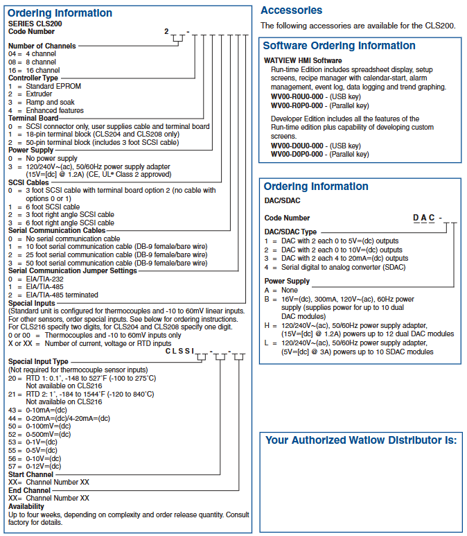
Rockwell SLC ™ 500 series 1747-L543 (SLC 5/04 controller)
Product core positioning
1747-L543 is Rockwell Automation (Allen Bradley) ®) SLC ™ The SLC 5/04 compact programmable logic controller (PLC) under the 500 series, with a core configuration of 64K memory and integrated RS232 and DH+communication functions, is mainly used for logic control and equipment linkage in industrial automation scenarios. It belongs to the category of modular programmable controllers and supports flexible system expansion and upgrading.
Key technical specifications
1. Basic and Storage Parameters
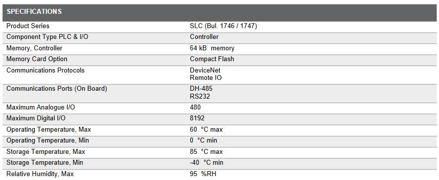
Parameter category specific specifications
Product series SLC (corresponding to manual numbers 1746/1747)
Component type PLC controller (belonging to Compact PLC Systems)
Controller memory 64 kB
The memory card option supports Compact Flash expansion
2. Communication capability
Communication protocol: Supports DeviceNet Remote IO protocol to meet the networking requirements of industrial grade devices.
Onboard communication port: Integrated with DH-485 and RS232 ports, it can directly connect devices corresponding to communication standards without the need for additional modules.
3. I/O expansion capability
Maximum Analog I/O: Supports up to 480 points, meeting the acquisition and control requirements of continuous signals such as temperature and pressure.
Maximum digital I/O: Supports up to 8192 points and can connect a large number of discrete devices such as switches, sensors, and actuators, adapting to complex industrial scenarios.
4. Environmental adaptability
Range of environmental parameter specifications
Working temperature (minimum) 0 ° C
Working temperature (maximum) 60 ° C
Storage temperature (minimum) -40 ° C
Storage temperature (maximum) 85 ° C
Maximum relative humidity of 95% RH (no mention of condensation, presumed to be an industry standard non condensing environment)
Supporting and Supporting Services
Peripheral accessory supply: We provide a full range of replacement and expansion parts, including power supplies, chassis, communication modules, I/O cards, and various accessories, to facilitate system maintenance and upgrades.
Communication upgrade option: Can be paired with 1747-AENTR Ethernet I/P adapter to upgrade the existing system to a distributed I/O architecture, enhancing network flexibility and coverage.
Technical support guarantee: NHP and Rockwell Automation provide continuous support, including lifecycle management strategies, to help users plan equipment updates and long-term use.
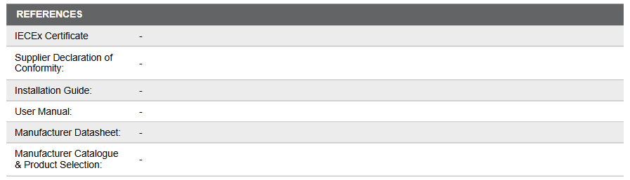
Certification and reference materials
Compliance certification: Possess IECEx certification (International Electrotechnical Commission Explosion proof Certification), comply with the Supplier Declaration of Conformity, and meet industrial safety and compliance requirements.
Reference documents: Provide installation guide, user manual, manufacturer datasheet, and product selection catalog for users to install, operate, and select.
Installation precautions
First, the importance of industrial equipment installation
In modern industrial production, various equipment and machines are widely used in various fields, such as manufacturing, energy industry, chemical industry and so on. The installation of industrial equipment is directly related to production efficiency and product quality. Proper installation and commissioning of good equipment can ensure the stable operation of the production line, improve production efficiency and product quality, reduce maintenance costs, and ensure the safety of employees.
Second, the steps of industrial equipment installation
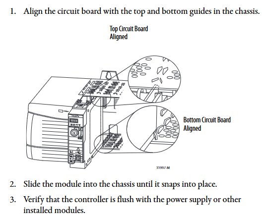
1. Preparation: Before the installation of industrial equipment, it is necessary to carry out adequate preparation work. This includes the tools and equipment required for installation, cleaning and preparation of the installation site, and making installation plans and schedules.
2. Determine the installation position: Determine the installation position of the equipment according to the requirements of the equipment and the layout of the production line. When determining the location, the weight and size of the equipment need to be considered, as well as the coordination of the equipment with the surrounding environment.
3. Install the device: Assemble and install the device according to the installation instructions. Ensure that the device is securely and accurately connected, while protecting the appearance and internal components of the device.
4. Connect power supplies and pipelines: For devices that require power supplies and power supplies, properly connect power supplies and pipelines. The connection of power supply and pipeline should comply with safety standards to avoid hazards such as electric shock and leakage.
5. Commissioning the device: After the installation is complete, you need to commission the device to ensure that the device can run properly. It includes checking the functions and performance of the equipment, adjusting the parameters and Settings of the equipment, and carrying out the necessary tests and inspections.
6. Training operators: After the installation of the equipment, it is necessary to train the operators to understand the operation methods and precautions of the equipment, and improve the operation skills and safety awareness of the employees.
Third, industrial equipment installation precautions
1. Safety first: When installing industrial equipment, safety is the most important consideration. You must operate in strict accordance with safety regulations and wear necessary protective equipment to ensure the safety of the workplace.
2. Strictly follow the equipment instructions: Industrial equipment usually comes with detailed installation instructions, you must carefully read and understand the contents of the instructions, and install the operation in accordance with the requirements of the instructions.
3. Pay attention to the assembly sequence: When installing the device, follow the correct assembly sequence to ensure that all components of the device are assembled correctly to avoid equipment failures or safety accidents caused by incorrect assembly sequence.
Applicable Industries
petroleum
Natural gas
chemical industry
cement
metallurgy
ship
mining industry
aviation
transport
Alcoa
machinery
manufacturing
car