Woodward 505 Digital Control for Steam Turbines
Application scenarios
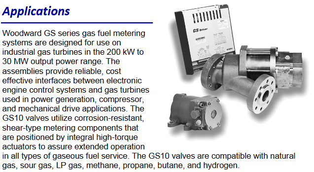
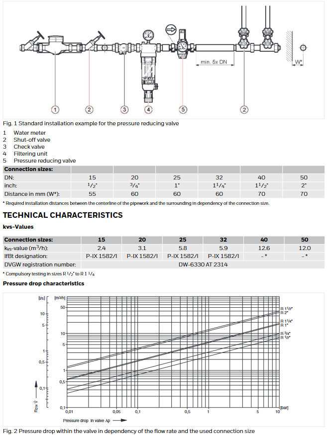
The Woodward 505 controller is designed for industrial steam turbines of various sizes and applications, and can start, stop, control, and protect industrial steam turbines or turbine expanders that drive generators, compressors, pumps, or industrial fans. Its unique PID structure is suitable for controlling steam equipment parameters, such as turbine speed, load, inlet manifold pressure, exhaust manifold pressure, or tie line power. It can achieve stable control and disturbance free mode switching during normal operation and equipment abnormalities, reducing process overshoot or overshoot.
Product description
Hardware and appearance
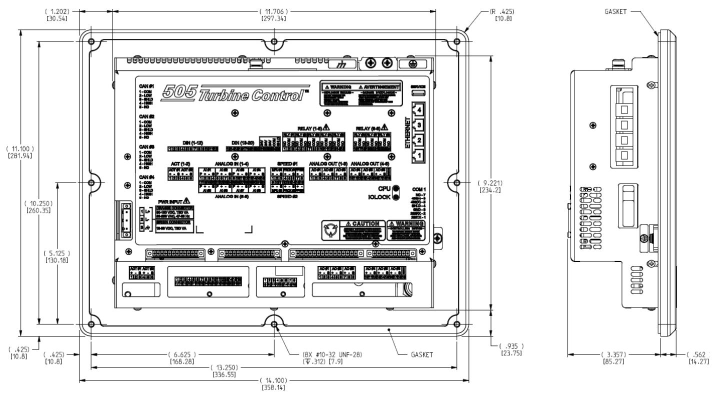
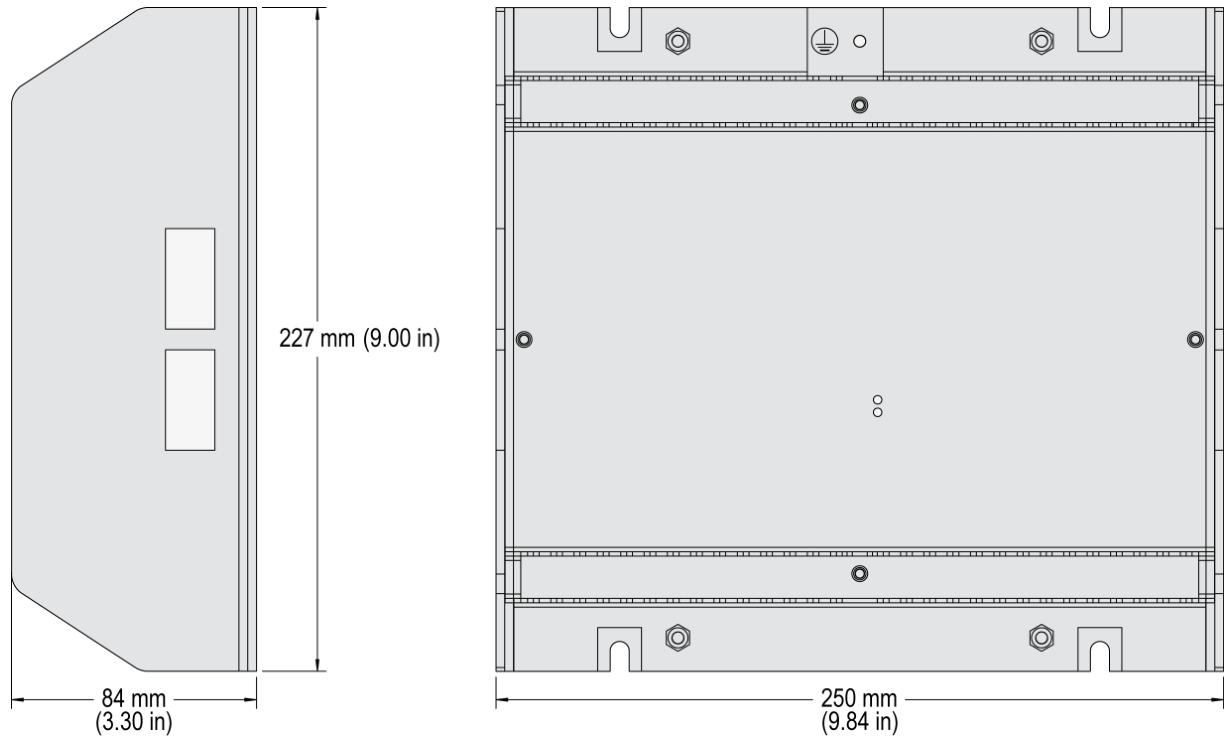
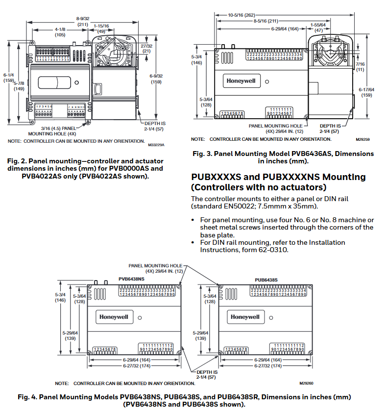
Adopting industrial grade reinforced casing, it can be installed in the system control panel of the factory control room or next to the turbine.
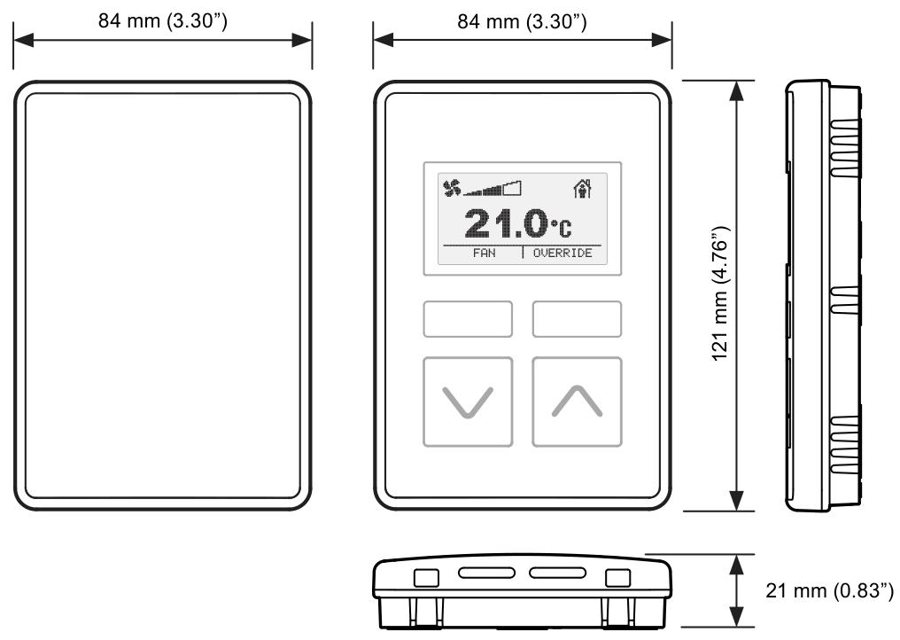
The front panel combines programming station and operator control panel (OCP) functions, equipped with an 8.4-inch (21cm) graphic display screen for engineers to program and operators to operate, and has password security protection program mode settings.
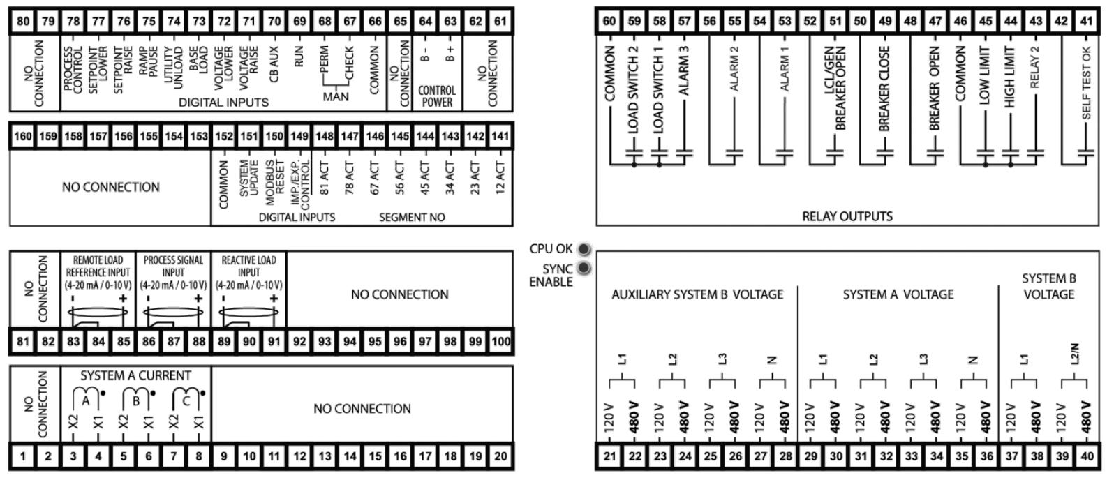
The input and output wiring of the turbine interface is located on the lower back panel of the controller, and the pluggable terminal block is convenient for system installation, troubleshooting, and replacement.
Core functions
It includes four PID controllers (speed, cascade, auxiliary 1, auxiliary 2), multiple startup programs (manual, semi-automatic, automatic, remote control), and multiple protection functions (overspeed, critical speed range, maximum power, etc.). Users can configure them according to specific turbine application requirements without the need for professional control engineers. After configuration, checks will be conducted to ensure there are no basic errors.
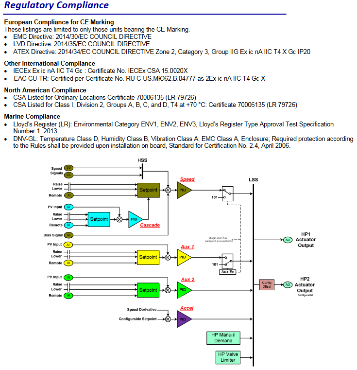
Equipped with on-site configurable, integrated graphical operator control panel, automatic start program, integrated first issue indicator, trip and alarm event recorder, user-friendly menu format, real-time trend screen, turbine running time log, real-time clock synchronization through SNTP, Ethernet communication and other features, it has the same appearance and function as the previous 505 version, adopts sulfur resistant conformal coating, and is certified for use in hazardous areas (low-voltage models).
Software tool
RemoteView software: It can be used as a remote operator control panel and/or engineering station, installed on remote computers or touch panels, and can perform all display functions of the 505 front panel. The password based login level security mechanism can manage the functional permissions of remote panel users.
Service tool suite: can download configuration settings files to 505, upload configuration settings files from 505 to other devices for saving, view real-time or saved trend files, etc.
Cost benefit design
The 505 controller integrates turbine control, system sequencer, operator control panel, and first output indicator functions, reducing external system equipment and system installation, wiring, and troubleshooting work. This controller can be configured on site, and professional factory personnel can make major functional changes on site. Minor functional changes can be made online when process changes require it. Its first indicator logic can indicate internal and external system related alarm and shutdown situations, greatly simplifying and reducing system troubleshooting work.
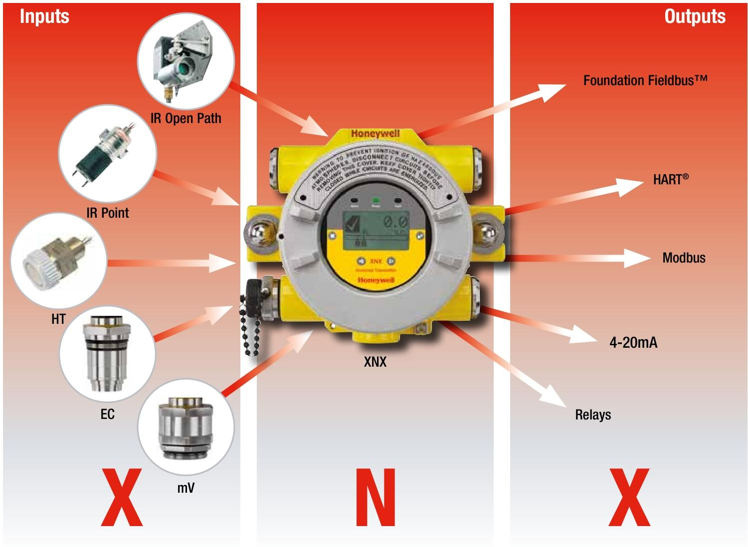
Communication function
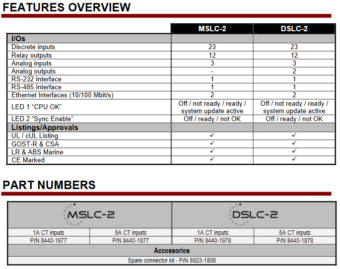
The 505 controller can communicate with the factory distributed control system and/or CRT based operator control panel directly through four Ethernet ports using Modbus TCP or OPC communication protocols, or through a serial Modbus port. A single serial port supports RS-232 or RS-485 communication using ASCII or RTU Modbus protocols, and can also communicate with factory DCS through a hard wired connection.
Control function
Available PID controllers: speed/load PID (with multiple dynamic and adaptive PID), extraction/intake pressure/flow PID, cascade PID (manifold pressure or tie line control), auxiliary PID 1 (limiter or control), inlet manifold PID, exhaust manifold PID, rotor acceleration PID (at start-up).
System Protection: Integrated overspeed protection logic and testing capabilities, first out indication (15 independent shutdown inputs), external alarm indication (15 independent alarm inputs), logic stuck in critical speed band, disturbance free switching between controls, local/remote control priority and selection, internal CPU watchdog circuit (to prevent faults), password security for operation and configuration modes.
Control Specifications
Input
Power supply
Low voltage (LV) model: 18-36 Vdc
High Voltage (HV) Model: 88-264 Vac and 90-150 Vdc
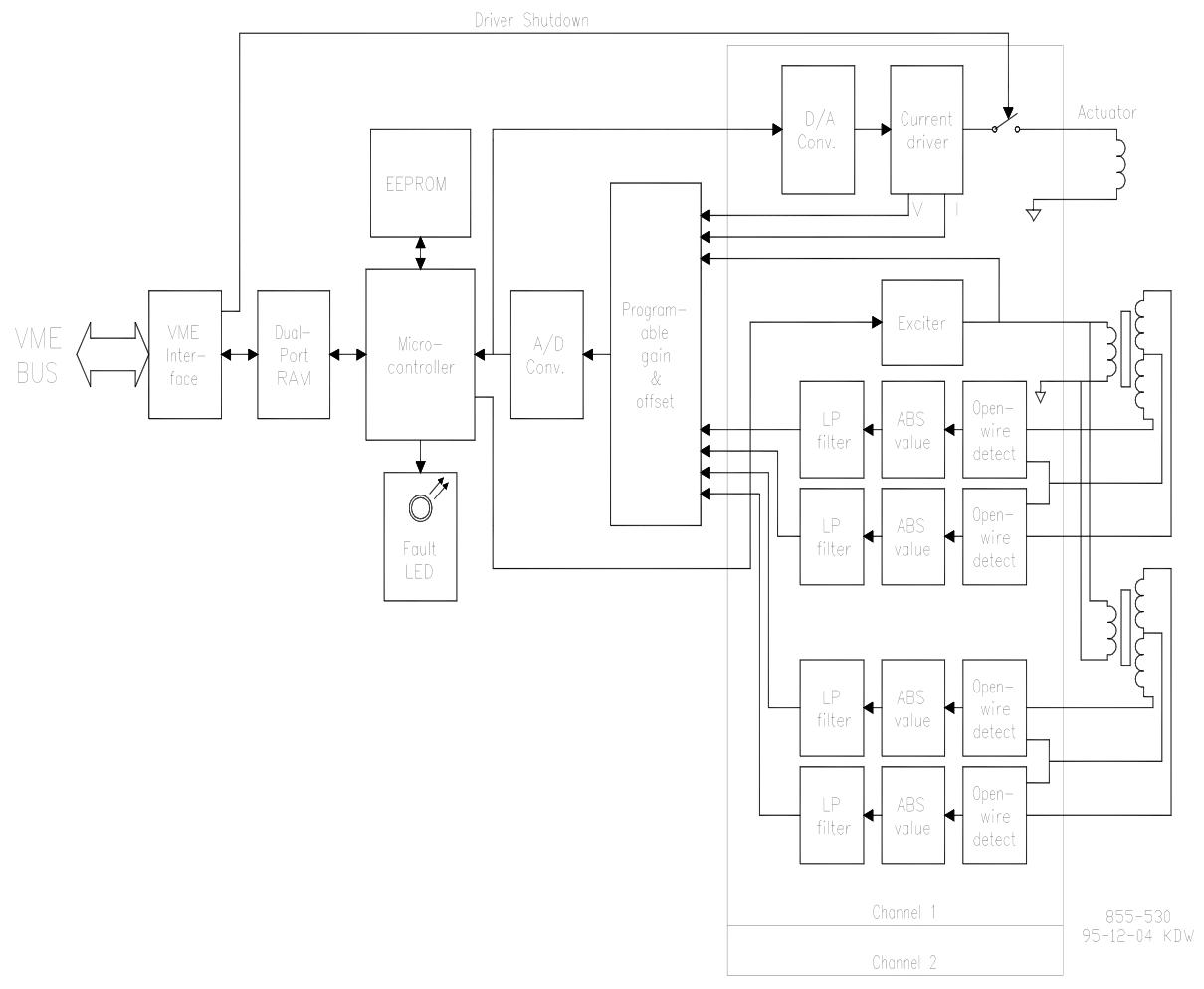
Speed: 2 passive magneto electric sensors (MPUs) or 2 active proximity probes, frequency range 0.5-35000 Hz
Discrete input: 20 configurable contact inputs, optional to add 16 additional inputs through LinkNet HT module
Analog input
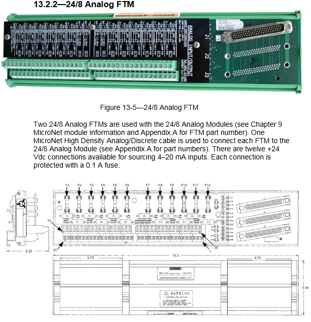
8 configurable 4-20 mA inputs
Optional to add 16 additional 4-20mA inputs through LinkNet HT module
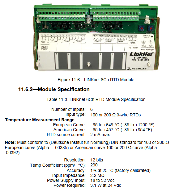
Optional to add 8 additional RTD inputs through LinkNet HT module
Output
Valve/actuator driver: 2 actuator outputs, supporting 4-20 mA or 20-200 mA
Discrete output: 8 configurable relay outputs with contact ratings of 24 Vdc @ 5 A
Analog output: 6 programmable 4-20 mA current outputs
Communication
Ethernet: 4 ports, supporting Modbus TCP or OPC protocols
Serial: 1 Modbus port (ASCII or RTU), compatible with RS-232 or RS-485
CAN: 4 ports, using Woodward CANopen protocol