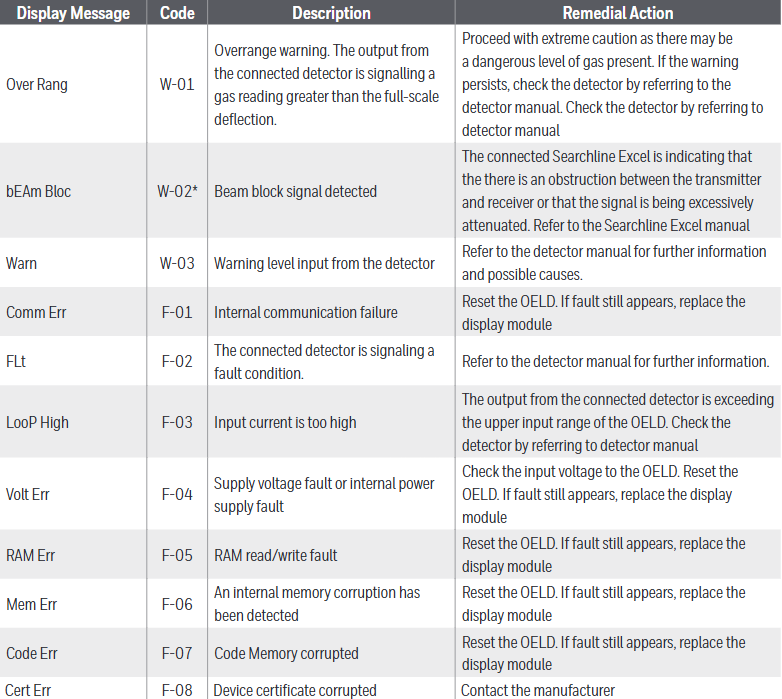
Honeywell Searchpoint Optima Plus Infrared Point Gas Detector
Product Overview
Searchpoint Optima Plus is an advanced infrared point type hydrocarbon gas detector suitable for potentially explosive environments. With its infrared detection principle, it has the characteristics of fast response, fault safe operation, etc., which can ensure factory compliance, personnel safety, and maximum uptime of the production process. Compared with traditional electrocatalytic gas detectors, it can reduce daily maintenance and overall cost of ownership.
Global application foundation: Based on over 40 years of design, manufacturing, installation, and maintenance experience, more than 100000 infrared point type hydrocarbon gas detectors have been installed worldwide, with a wide range of application scenarios, from light industry to demanding offshore petrochemical environments.
Typical applications: including environments where catalytic bead toxins or inhibitors may exist, as well as harsh environments that require extended daily maintenance intervals, such as offshore oil and gas platforms, floating production storage and offloading (FPSO) vessels, oil tankers, onshore oil and gas terminals, refineries, LNG/LPG bottling plants, etc.
Detectable gases: Over 100 types of gases and vapors can be detected. For specific lists, please consult the customer support team or local distributors.
Core advantages
Advantages of infrared technology: It has the characteristics of fault safe operation, fast response speed, reduced daily maintenance, not affected by catalytic toxins, long service life, and can work in inert environments.
Product Features:
Accumulated experience in installing over 100000 units worldwide, with higher reliability.
Optional HART ® The protocol outputs through 4-20mA.
Can detect various hydrocarbon gases, including solvents.
No moving parts, higher reliability; The self compensating optical system enhances stability and is not affected by long-term component drift.
Capable of remote functional gas testing and certified for hazardous areas in North America and Europe.
Enhance false alarm elimination capability, with pollution optical warning to improve uptime, dynamic heating control to ensure no condensation or undetected faults in the optical system.
Improved diagnostic functions, integrated event logs, reduced power consumption, and certified through various hazardous area classification schemes such as ATEX, UL, CSA, IECEx, etc.
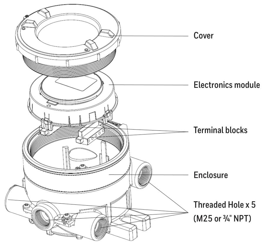
Core Technologies and Components
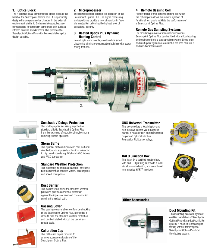
Optical module: The 4-channel (dual compensation) optical module is the core, which not only compensates for external environmental changes like the 2-channel design, but also compensates for long-term component drift such as infrared light sources and detectors, providing the most stable optical design.
Microprocessor: controls the operation of the detector, and its signal processing and algorithms reach new heights in false alarm elimination, providing the highest level of operational integrity.
Heating optical system and dynamic heating control: The heated optical components are monitored by intelligent electronic devices, which have energy-saving functions and can eliminate condensation accumulation.
Remote gas injection unit: The optional remote gas injection unit is installed in the optical path at the factory and can remotely inject functional test gases to verify detector performance.
Sampling system and accessories
Remote gas sampling system: For remote or difficult to access locations, flow enclosures can be equipped and integrated into the gas sampling system, providing single point and multi-point systems suitable for hazardous and non hazardous areas.
Main accessories:
Sunshade/Rain Protection: Standard multifunctional accessories to protect the detector from extreme environmental impacts and ensure reliable operation.
Storm Barrier: Optional barrier to reduce wind chill, salt, and dust accumulation in high wind exposure applications.
Standard weather protection: Standard equipment, achieving the best balance between waterproof/dustproof and response speed.
Dust barrier: Installed inside the standard weather protection, it additionally prevents dust and pollutants from entering the light path.
Gas injection cover: can confirm the performance of the detector, closely matched with standard weather protection, and can be installed without special tools.
Calibration cap: used to achieve accurate calibration of detectors.
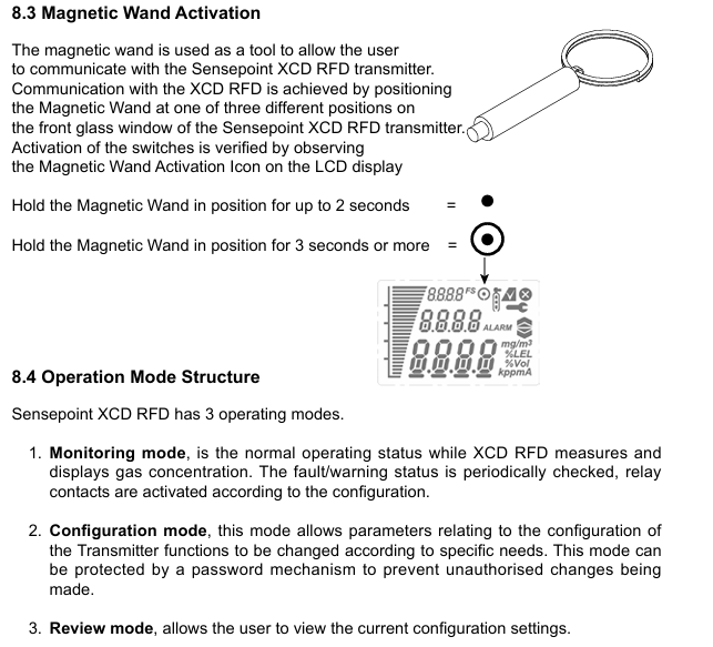
XNX Universal Transmitter: Provides local display and non-invasive access through magnetic switches, with HART capability ® Communication output and optional Modbus, Foundation fieldbus, or relays.
HALO junction box: Ex e certified junction box with LED halo for local visual status indication, optional non-invasive HART ® Interface.
Pipeline installation kit: Installation plate device, which can install the detector in the pipeline/ventilation system without removing it from the pipeline system for functional gas testing.
On site inquiry tool: The multifunctional handheld interrogator (SHC-1) is a certified debugging/maintenance tool for hazardous areas, which can reconfigure detectors to adapt to different gases and perform fault diagnosis. It can also be used for raw Searchpoint Optima and Searchline Excel (open circuit gas detectors), reducing operator training.
Terminal/Installation Accessories: Provide a full range of hazardous area certified Ex e and Ex d junction boxes, as well as SHC-1 protective devices, to provide electrical protection for SHC-1 when using conventional terminal enclosures.
HART ® communication protocol
Protocol advantage: HART ® Highway Addressable Remote Transformer is a widely used digital communication protocol that allows users to obtain real-time data, status indicators, and diagnostic information from smart field devices by superimposing digital signals on existing analog signals, without the need for additional field wiring, helping to reduce costs. If dedicated handheld devices are not required, engineers can use a single HART ® Handheld devices access all HART devices on site ® Enable the device and query HART at any position in the current loop ® Signal, diagnostic information can be obtained without the need to go to the site, reducing maintenance costs.
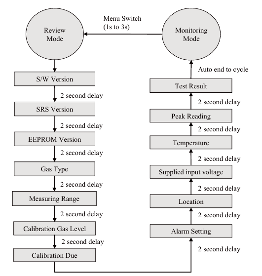
The detector supports functions such as viewing gas readings, configuration, and diagnostic information, conducting collision testing, mA loop calibration, gas calibration, simulating alarms, faults, or warnings, setting device tags, IDs, and descriptions, viewing activity warning/fault and event history, forcing mA output to a specific level for testing, configuring real-time clock, configuring suppression, warning, and over range levels, configuring alarm thresholds, changing target gases, and password protected access.
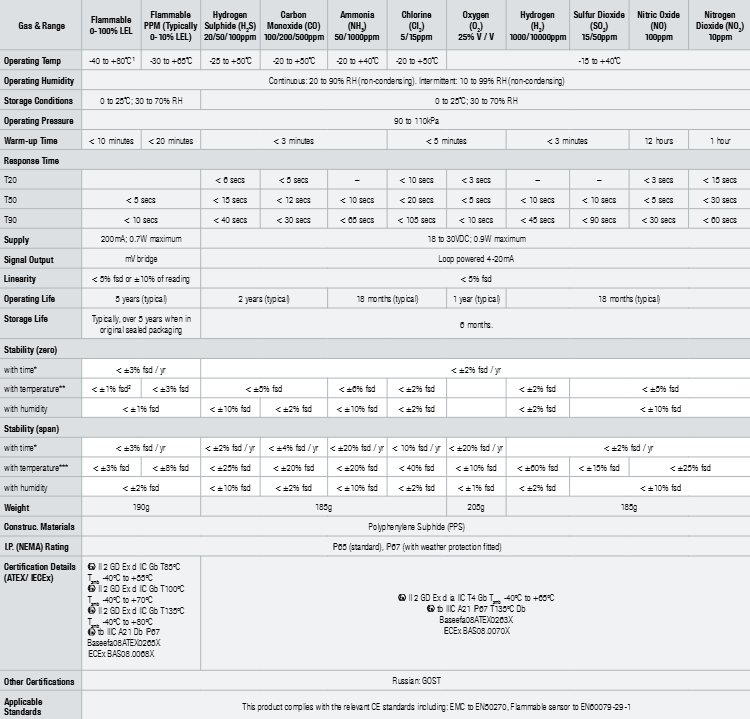
Technical specifications
Project/Details
Measurement range: 0-100% LEL, calibrated for various hydrocarbon gases and vapors, providing different measurement ranges and solvent calibrations for special applications
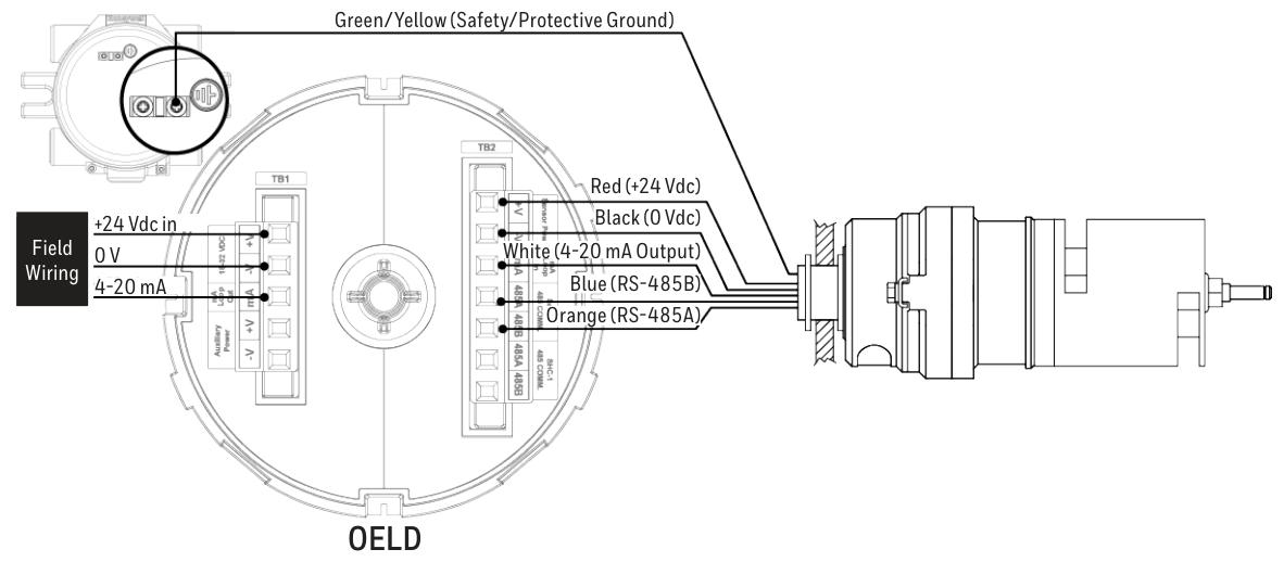
Signal output: 4-20mA automatic sensing sink or source, suppression: 1-3mA (default 2mA), warning: 0-6mA (default 3mA *), fault: 0mA (HART) ® Unit adjustable to 1mA, over range: 20-21.5mA (default 21mA)
Digital output: optional multi-point Modbus RS485 via XNX, optional HART ® Through 4-20mA output (HART) ® Version 7)
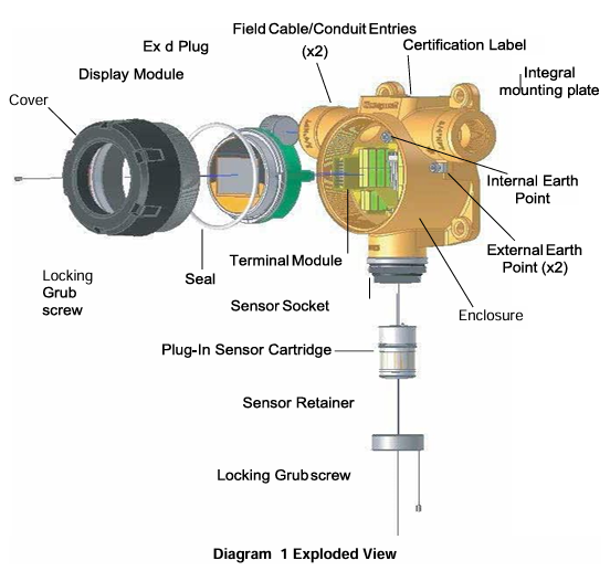
Material: 316 stainless steel
Weight: 1.6kg
Precision Optima Plus (hydrocarbons): baseline<± 1% FSD, 50% FSD<± 2% FSD; Optima Plus (ethylene): baseline<± 2% FSD, 50% FSD<± 3% FSD
Linearity:<5% FSD
Response time: T50<3 seconds, T90<4 seconds (methane)
Operating and certification temperature range: -40 ° C to+65 ° C * *; CU-TR-EX (Russia) certification – XTC version, certified temperature range -60 ° C to+65 ° C
Long term stability (as defined in EN 60079-29-1): baseline methane 100% LEL range: ≤± 2% FSD; Ethylene 100% LEL range: ≤± 4% FSD; 50% FSD methane 100% LEL range: ≤± 4% FSD; Ethylene 100% LEL range: ≤± 5% FSD
Drift within temperature range (-40 ° C to 65 ° C): baseline ≤ ± 2% FSD; 50% FSD methane 100% LEL range: ≤± 0.131% FSD/° C; ethylene 100% LEL range: ≤± 0.078% FSD/° C
Pressure change impact: 0.1% (reading)/mbar
Power supply 18-32Vdc: (nominal 24Vdc), maximum<4.5W
Environmental Protection: IP 66/67
Diagnosis (and recalibration): Certified handheld interrogator, XNX, or optional HART ® communication
Safety certification: ATEX, UL/CSA, IECEx, CU-TR-EX (Russian Customs Union) and other certifications
Performance certification: EN 60079-29-1, CSA C22.2 152., FM ANSI/ISA-12.13.01., Russian mode approval (metrology) – XTC version, etc***
Functional Safety: IEC61508 Safety Integrity Level 2
EMC compliance: EN 50270:2006, EN 50271:2010
Ship certification: Marine Equipment Directive (MED), DNV, BV, ABS, Lloyd’s Register and other type approvals
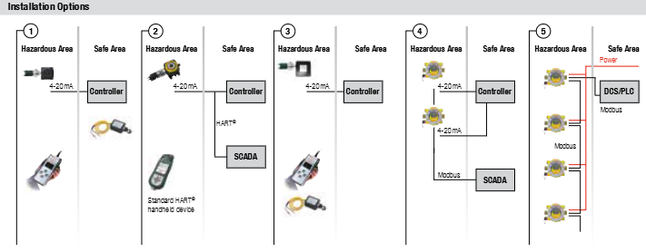
Installation Options
Installation options: Provides multiple installation configurations to adapt to different connection requirements in hazardous and safe areas, such as connecting to controllers, DCS/PLC, SCADA systems, etc., supporting HART ®、 Modbus and other communication methods.