Honeywell Unipoint is a DIN rail mounted single channel gas detection controller designed specifically for indoor safe areas to integrate detection functions for flammable, toxic gases, and oxygen. It is compatible with various types of gas detectors, providing integrators with flexible and economical solutions. It can build small and medium-sized monitoring systems and is widely used in industrial and commercial scenarios that require gas detection.
Core version and compatibility
MV Input Version: Suitable for 3-wire mV bridge type combustible gas detectors (such as SignalPoint, SensePoint series combustible detectors), coded as 2306B2000.
4-20mA input version: compatible with detectors with 2-wire or 3-wire 4-20mA output (such as SignalPoint, SensePoint series toxic gas and oxygen detectors, SensePoint Plus series), encoded as 2306B1000.
Key functions and features
Detection and alarm:
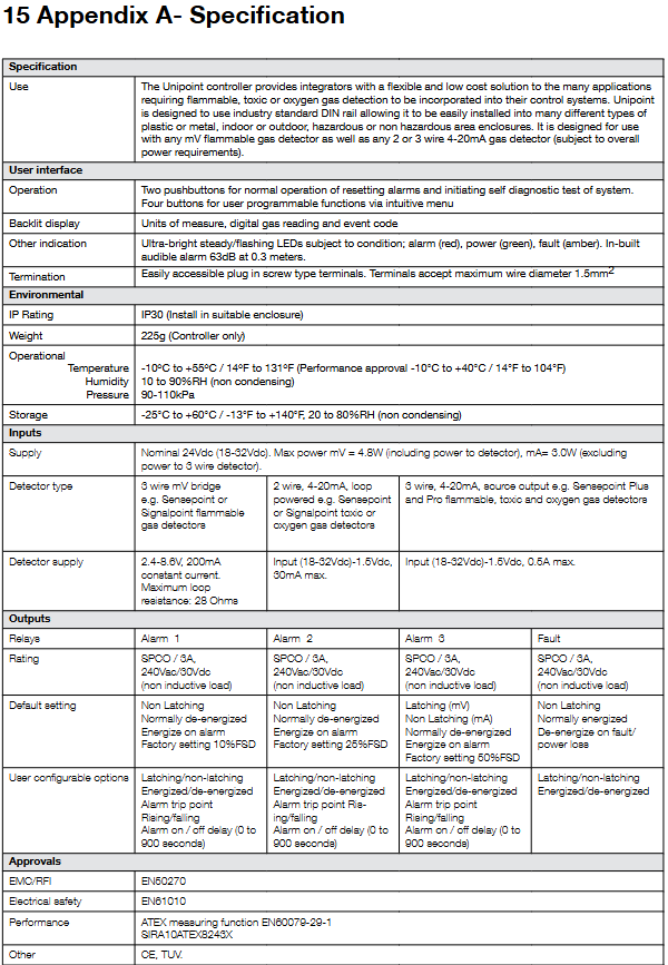
Supports 3-level programmable alarm relays and 1-channel system fault relays, with a relay rating of 3A (240Vac/30VDC, non inductive load).
Integrated audio-visual alarm function, including backlit LCD display (gas concentration, unit, event code), three color LED indicator lights (red alarm, green power, yellow fault/suppression), and built-in speaker.
Configuration flexibility:
Parameter settings can be made through four buttons (up, down, confirm, reset), and password protection is supported to prevent unauthorized access.
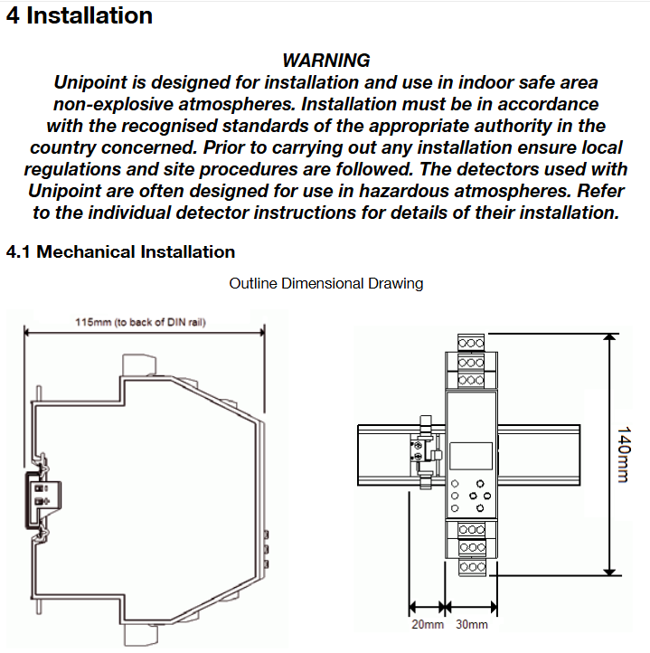
Adopting standard TS35 DIN rail installation, with dimensions of 140 × 30 × 115mm, weight of 225g, and protection level of IP30 (to be installed in a suitable housing).
Support multi module expansion, up to 8 (3-wire mV or 2-wire mA detectors) or 4 (3-wire mA detectors) controllers can be installed on the same DIN bus.
Key points of technical parameters
Power supply: nominal 24Vdc (18-32Vdc), maximum power consumption of 4.8W in mV version (including detector power supply), 3.0W in mA version (excluding 3-wire detector power supply).
Working environment: Temperature range of -10 ° C to+55 ° C, humidity range of 10-90% RH (non condensing).
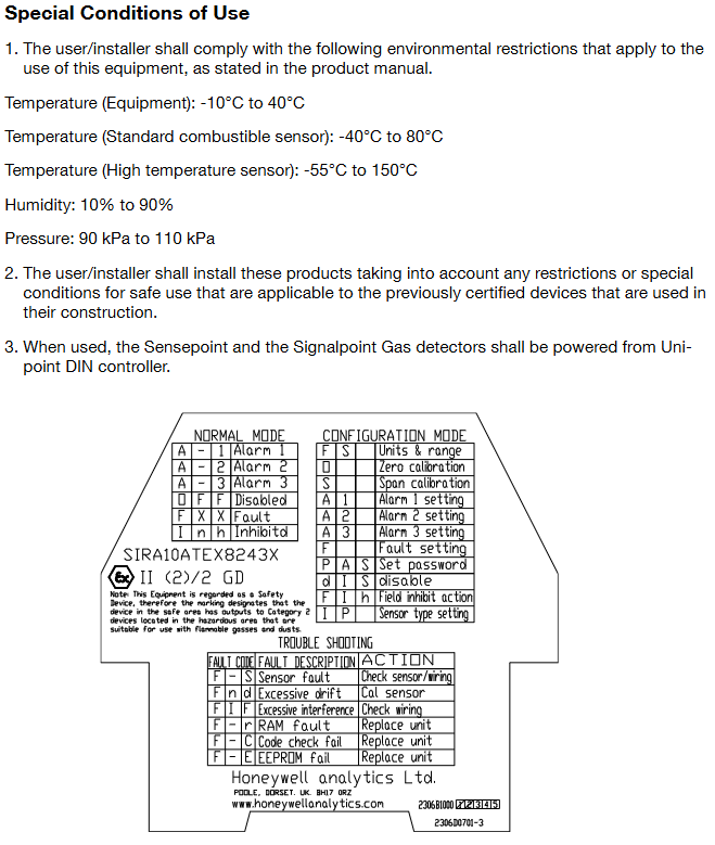
Certification: Compliant with EN50270 (EMC/RFI), EN61010 (Electrical Safety), ATEX EN60079-29-1 (Measurement Function) and other standards, with CE and TUV certifications.
Typical application scenarios
By connecting multiple modules, it can adapt to the small and medium-sized gas monitoring needs in the fields of petrochemicals, semiconductors, water treatment, building services, etc. It is compatible with various detectors under Honeywell and third-party equipment that meets specifications.
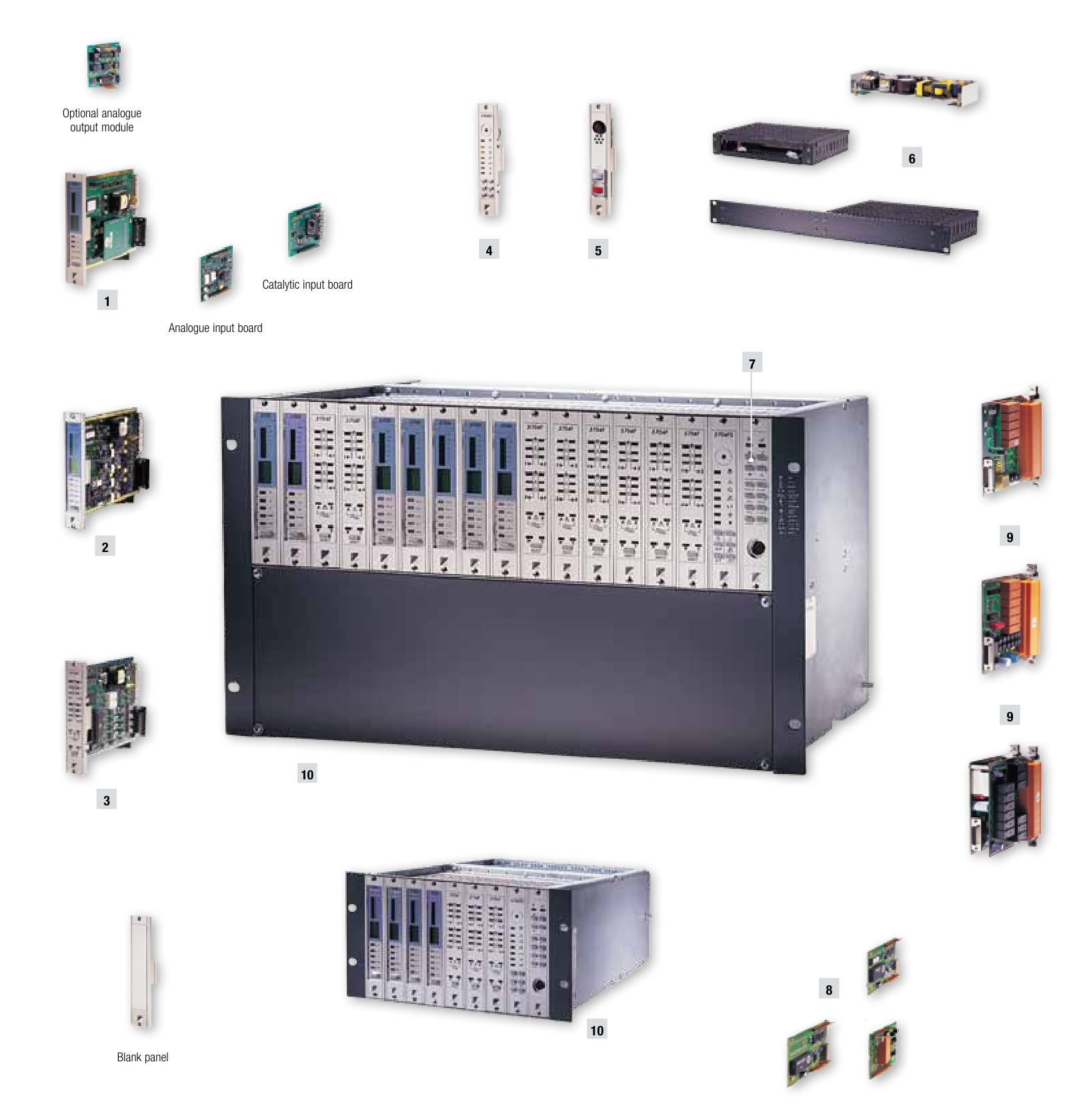
Honeywell’s System 57 is an advanced intelligent gas detection system management product with about half a century of experience in gas detection systems, providing protection for factories and personnel against flammable and toxic gas hazards. It has a wide range of applications, from small and simple systems to large-scale comprehensive fire and gas detection systems worldwide. The system adopts a modular design with high flexibility to meet the unique needs of different applications. It can receive inputs from multiple detectors and has multiple output modes. It can be installed in wall cabinets or panel mounting racks, and can be used independently or integrated into the core of fire and gas systems.
Core functions and technical features
Control technology: It features high-precision intelligent control, main/voting alarm options, high packaging density, flexible I/O configuration, and relay output options.
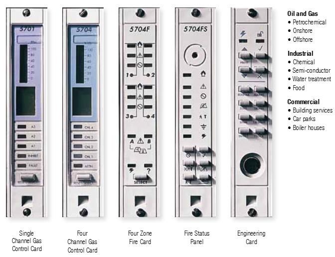
Card type and function
5701 gas control card: 1 inch wide, single channel control, supports plug-in input and output, has independent single channel operation and other functions.
5704 gas control card: 1 inch wide, four channel control, with multiple output options and different channel display selection methods.
5704F fire control card: 1 inch wide, four zone fire control, with 2 line monitoring outputs, 19 inch rack can hold up to 15 cards.
5704FS Fire Status Panel: Each rack containing a 5704F fire card must be equipped with one, providing public display, alarm indication, local sound alarm, and related button functions.
Other key components
Main alarm update panel: optional, 1 inch wide, with sound and visual alarms and reset and accept buttons, providing update function without external wiring.
Power supply unit: rack mounted, with different specifications, supports automatic induction of input voltage, output DC voltage stabilization, and has overvoltage and overload protection.
Engineering card: provides full maintenance and setting functions, with buttons to check the alarm level and performance of each channel, built-in real-time clock provides calibration history and reminder functions, and also has features such as security protection.
Engineering card module: There are plug-in options such as serial communication module, RS232 printer driver module, main alarm update module, etc., which can expand system functions.
Interface card: There are 9 versions that connect various fire or gas detectors and control cards, with multiple functions.
Rack components: provide installation options for control cards and interface cards, with different specifications and support for multiple channel configurations.
Cabinet components: Convenient and compact installation of rack components and power supplies, with different versions and specific protection levels.
DC input card: directly connected to the engineering card, providing a power connection point for the entire rack and having multiple protection functions.
Summary of Technical Parameters
5704F Fire Card Specification: Includes various parameters of the 5704 Fire Card and 5704 Fire Status Panel, such as supply voltage, power consumption, operating temperature, weight, certification, etc.
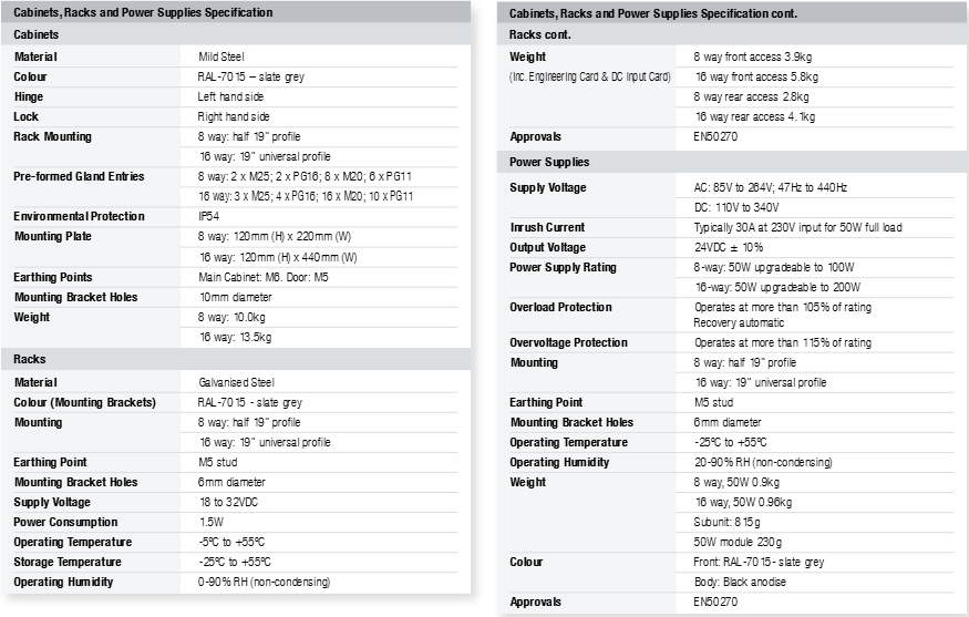
Cabinet, rack, and power specifications: involving materials, colors, hinges, locks, installation methods, glass entrances, environmental protection, dimensions, weight, supply voltage, power consumption, working environment, certification, and other parameters.
5701/4 gas card specifications: including control card display, front panel facilities, remote facilities, supply voltage, display/alarm points, electronic drift, working environment, size, weight, certification, and related input/output parameters.
Interface card specifications: involving relay contacts, operation, power consumption, terminals, working environment, weight, certification and other parameters.
Engineering card module parameters: including power consumption, working environment, weight, authentication and related communication, input and output parameters of serial communication module, RS232 printer driver module, main alarm update module, etc.
Application area
Suitable for multiple fields such as oil and gas (petrochemical, onshore, offshore), industry (chemical, semiconductor, water treatment, food), and commerce (construction services, parking lots, boiler rooms).
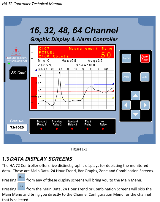
HA72 is a high-performance multi-channel gas detection controller launched by Honeywell, supporting 16, 32, 48, or 64 channel configurations. Its core functions are real-time monitoring, alarm control, and data management, suitable for safe monitoring of toxic gases, flammable gases, and oxygen content in industrial environments. Its design emphasizes high scalability, flexible communication, and intelligent operation. It can receive data through analog signals, Modbus protocol, or wireless methods, and supports remote monitoring and configuration.
Core functions and features
1. System configuration and input/output
Channels and inputs: Supports up to 64 channels, compatible with analog signals (4-20mA, mV), Modbus RTU/TCP, wireless data transmission, and can directly connect to catalytic bead sensors, RTD temperature sensors, and other devices.
Output and Control:
Standard configuration includes 5 SPDT relays (3 programmable alarm relays, 1 fault relay, and 1 horn relay), supporting 3 levels of independent alarms (high, medium, and low thresholds can be set for each channel).
Optional discrete relay board (16 channels/board), programmable relay board (16 channels/board), and 4-20mA analog output board are available for driving external devices such as sound and light alarms and valves.
Power Supply and Power Consumption: Supports 24VDC power supply (10-30VDC), optional 600W or 150W AC/DC power supply (110-240VAC input), total power consumption varies with configuration (such as adding 6.5W per discrete relay board).
2. Display and operation
Interface design: 320 × 240 pixel color graphic LCD, providing 5 data views (main data screen, 24-hour trend chart, bar chart, combination view, area screen), supporting visual display of engineering units and alarm thresholds.
Operation mode: Non invasive magnetic keyboard (suitable for hazardous areas), supports password authorization mode (locking key configurations), built-in calibration mode (zero/range calibration).
Alarm indication: Each channel is displayed in green yellow red three color status (normal/fault/alarm), and the sound alarm is achieved through the built-in piezoelectric buzzer or external speaker, supporting remote reset and mute functions.
3. Communication and Data Management
Communication interface: Comes standard with 2 RS-485 ports (configurable as master/slave mode), optional with 2 isolated RS-485 ports, supports Modbus TCP/IP (Ethernet port), and can be networked with multiple machines (up to 128 HA72).
Data recording: Supports SD card storage configuration, event logs, and historical data (recording channel Min/Max/Avg values every 10 minutes), optional printer interface (real-time printing of alarm events with timestamps).
Remote monitoring: Built in web server, accessed through Ethernet, supports remote viewing of status, configuration parameters, and downloading logs.
4. Environmental adaptability and certification
Protection level: Multiple enclosure options are available, including NEMA 4X (fiberglass, dustproof and waterproof), NEMA 7 (aluminum alloy, explosion-proof, suitable for Class I, Div. 1/2 hazardous areas).
Working environment: temperature -25 ° C to+60 ° C, humidity 0-90% (non condensing), altitude up to 2000 meters.
Certification standards: Compliant with ISO 9001 quality management system and compatible with multiple international safety standards (such as UL, CSA).
Clock/printer interface board, 600W/150W power module.
Installation method: Supports panel installation, 19 inch rack installation, or wall mounted installation, with preset cable entry to simplify wiring.
Applicable scenarios
Typical applications: Chemical parks, oil and gas facilities, large factories, and other scenarios that require multi-point gas monitoring can be linked with Honeywell XNX, XCD and other series detectors to form a complete system.
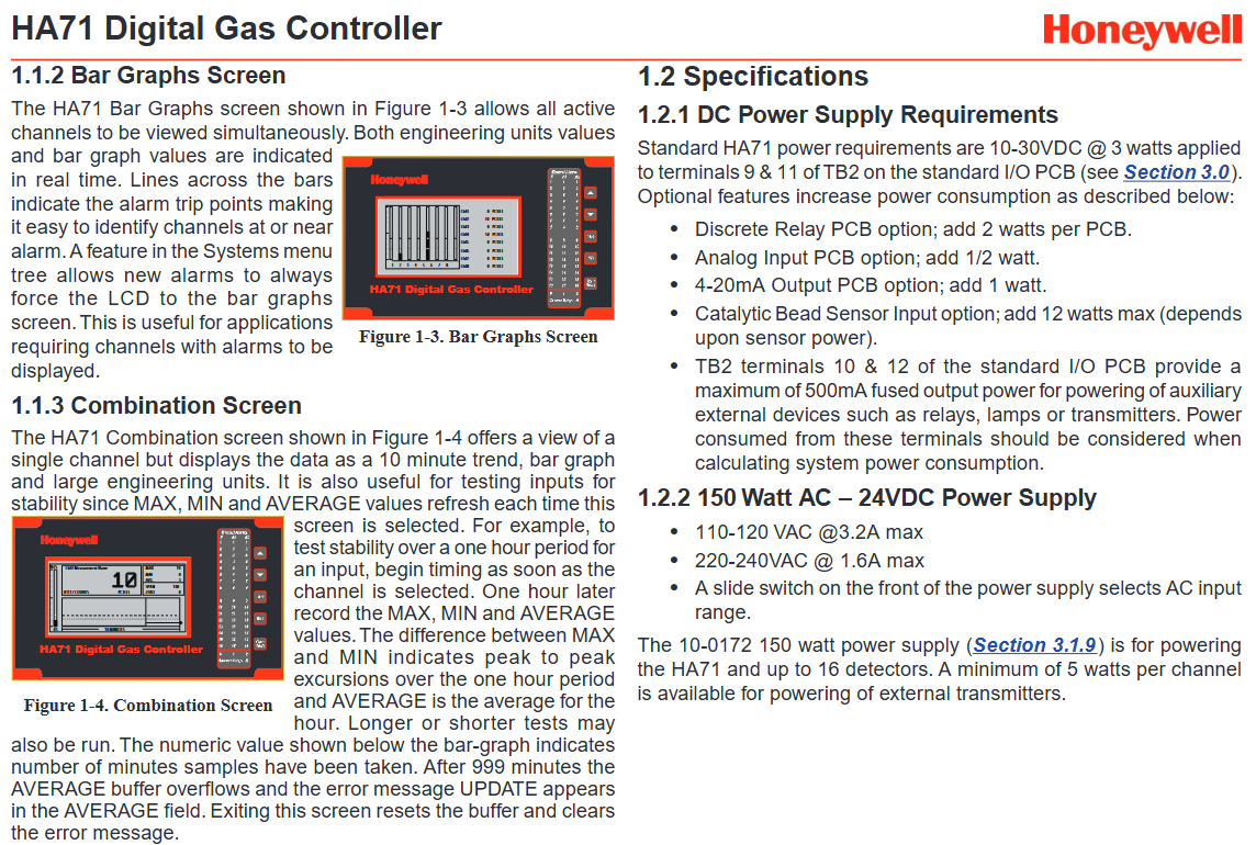
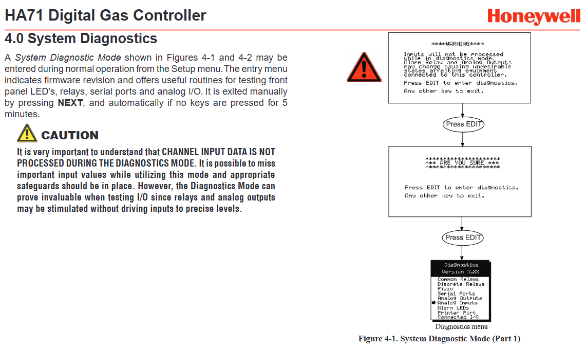
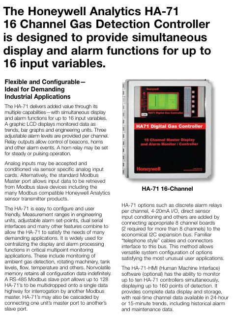
HA71 is a multi-channel digital gas controller launched by Honeywell, supporting up to 16 detection channels (configurable as 8-channel mode). Its core functions are real-time monitoring, alarm control, and data management, suitable for safe monitoring of toxic gases, flammable gases, and oxygen content in industrial environments. Its design emphasizes modular expansion, high reliability, and flexible communication capabilities, which can receive data through analog input or Modbus protocol, and support integration with upper level systems such as PLC and DCS.
Core functions and features
1. System configuration and input/output
Channels and inputs: Basic support for 8 channels, expandable up to 16 channels, compatible with analog signals (4-20mA, mV) and Modbus RTU protocol inputs, can directly connect catalytic bead sensors, RTD temperature sensors and other devices.
Output and Control:
Standard configuration of public alarm relays (A1, A2, fault, horn), supporting 3-level independent alarms (high, medium, and low alarm thresholds can be set for each channel).
Optional discrete relays (corresponding to 12/24 channels per channel) and 4-20mA analog outputs are available for driving external devices such as sound and light alarms and valves.
Power supply and power consumption: Supports 10-30VDC power supply, optional 150W AC/DC power supply (110-240VAC input, 24VDC output), total power consumption up to 210W (including expansion unit).
2. Display and operation
Interface design: 240 × 128 pixel graphic LCD, providing 3 data views (bar chart, 24-hour trend chart, combination view), supporting visual display of engineering units and alarm thresholds.
Operation mode: Non invasive magnetic keyboard (suitable for hazardous areas), supports password authorization mode (locking key configurations), built-in calibration mode (zero/range calibration).
Alarm indication: Each channel is equipped with green yellow red three color LED (normal/fault/alarm), and the sound alarm is ≥ 70dB@1 Mi, supports remote reset and mute functions.
3. Communication and Data Management
Communication interface: comes standard with dual Modbus RS-485 ports (master-slave mode), supports Modbus TCP/IP (optional 10 BaseT Ethernet), and can be networked with multiple machines (up to 128 HA71).
Data recording: Supports SD card storage configuration, event logs, and historical data, with optional printer interface (real-time printing of alarm events with timestamps).
Environmental adaptability and certification
Protection level: Multiple enclosure options are available, including NEMA 4X (dustproof and waterproof, suitable for outdoor use), 316 stainless steel enclosure (corrosion-resistant), NEMA 7 explosion-proof enclosure (suitable for Class I, Div. 1/2 hazardous areas).
Working environment: temperature -25 ° C to+50 ° C, humidity 0-90% (non condensing), altitude up to 2000 meters.
Certification standards: Compliant with safety and electromagnetic compatibility standards such as CSA C22.2, UL 1604, EN 55011, etc., with a safety integrity level of SIL2.
Clock/printer interface board (supports parallel/serial printing, records alarm events).
Installation method: Supports wall mounted, panel mounted, or 19 inch rack mounted installation, with preset cable entry (PG16/M20 specification) to simplify wiring.
Applicable scenarios
Typical applications: Chemical workshops, oil and gas facilities, laboratories, and other scenarios that require multi-point gas monitoring can be integrated with Honeywell Sensepoint series detectors to form a complete system.
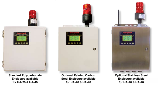
The HA-20, HA-40, and HA-71 series gas detection controllers launched by Honeywell are designed specifically for monitoring gas detection points from 1 to 16 channels, balancing high safety and cost-effectiveness. These controllers are suitable for harsh industrial or commercial environments, with NEMA 4X and explosion-proof enclosure options, and can be deployed in hazardous areas for monitoring toxic gases, flammable gases, and oxygen content. The core advantages are multi-channel monitoring, flexible expansion, and high environmental adaptability.
Core functions and features of each model
HA-20 and HA-40 controllers
Channels and inputs:
HA-20 supports 2 4-20mA sensor inputs, HA-40 supports 4, both of which are suitable for long-distance sensor signal transmission.
Built in 24VDC power supply, with a total power of 15W (optional 50W power supply to expand wiring space).
Alarm and Control:
Each channel contains 3 independent alarm levels and supports relay confirmation function (can mute external sound devices when an alarm is triggered).
Standard configuration includes 2 SPDT common alarm relays (for HORN, HIGH, Warning, or FAULT states), and optional independent channel alarm relays.
Display and operation:
Graphic LCD display screen, displaying data in bar charts, trend charts, and engineering units; The alarm LED flashes when a new alarm is triggered and remains on after confirmation.
Adopting touch and magnetic keyboards, supporting non-invasive operations in hazardous areas; Equipped with calibration mode (zero/range calibration) and authorization mode (locking key configuration parameters).
Certification and compatibility:
Obtained CSA certification (C22.2 NO.152), suitable for combustible gas detection, compliant with Class I, Div. 2, Groups A, B, C, D, and CE markings.
Optional RS-485 Modbus slave port (supporting 128 HA-40 multi machine networking) or 10 BaseT Ethernet (Modbus TCP/IP protocol).
HA-71 controller
Channels and inputs:
Supports up to 16 inputs, compatible with analog signals or Modbus protocol, and can obtain data through RS-485 to reduce wiring costs.
Provide 8-channel display mode, with optional expansion board to meet economical configurations below 8 channels.
Functions and extensions:
Each channel has 3 adjustable alarm levels and is equipped with SPDT common alarm relays (HORN, HIGH, Warning, FAULT) as standard.
Supports dual Modbus RS-485 serial ports and optional telephone modems, and adds discrete alarm relays, 4-20mA I/O, and other functions through the I ² C expansion bus (2 expansion boards are required for channels exceeding 8).
Software and Monitoring:
HA-71-HMI software is optional, which can simultaneously monitor 10 HA-71 controllers (up to 160 detection points), support real-time data display, 24-hour/15 minute trend analysis, and historical alarm recording.
Common advantages and applicable scenarios
Environmental adaptability: Both provide NEMA 4X (Div. 2 certification) and explosion-proof wall mounted enclosure options, suitable for deployment in hazardous areas.
Flexibility: Supports optional functions such as Modbus protocol (RS-485 or TCP/IP), data recording, 4-20mA output, etc., to meet different integration requirements.
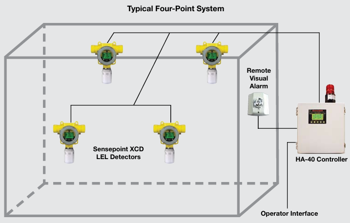
Typical application: Suitable for multi-point gas monitoring scenarios, such as factory workshops, chemical facilities, etc., it can be linked with Sensepoint XCD and other detectors to form a complete system (such as a typical four point system including HA-40 controller, remote visual alarm, and operator interface)
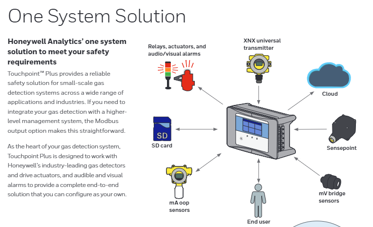
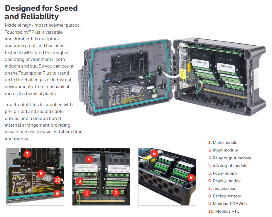
Touchpoint Plus is a wall mounted control center designed by Honeywell specifically for small gas detection systems, aimed at providing reliable gas safety monitoring solutions for industrial environments through modular design and intuitive operation. The system supports up to 16 gas detection channels (8 basic units, increased to 16 with expansion units), suitable for various scenarios such as mechanical workshops, chemical plants, laboratories, etc. The core advantage lies in the deep integration of reliability, flexibility, and usability.
Core functions and features
1. High reliability design
Industrial grade durability: The shell is made of polycarbonate ABS high impact polymer plastic, with dust and water resistance (IP65, NEMA 4X certification), and can operate stably in continuous working temperatures ranging from -10 ° C to+55 ° C (humidity ≤ 95% non condensing) and harsh vibration environments, suitable for complex indoor and outdoor industrial scenarios.
Continuous operation guarantee: Equipped with a built-in 22.2V lithium battery (2600mAh), it can provide backup power for more than 30 minutes under typical systems, avoiding monitoring interruptions caused by sudden power outages.
Compliance certification: Compliant with multiple international safety standards, including electromagnetic compatibility (EN 50270:2015), electrical safety (UL 61010-1), safety integrity (IEC 61508:2010 Ed.2 SIL2), and applicable to Class I, Division 2 and other hazardous areas, ensuring safe use in flammable and explosive environments.
2. Flexible system configuration and compatibility
Modular Expansion:
The basic unit supports 2/4/8 channel inputs (mA or mV signals), and the expansion unit can increase the total number of channels to 16, meeting the detection needs of different scales.
Rich output options: 12/24 relay outputs (supporting NO/C/NC switching, 1.7A@30VDC /250VAC)、 4/8-channel 4-20mA isolated output, capable of driving valves, fans, and other equipment or linking external alarm systems.
Wide compatibility: Compatible with Honeywell’s full range of gas detectors, including:
Basic type: such as Sensepoint (supporting direct power supply for 8 devices, requiring invasive configuration);
Enhanced: such as Sensepoint XCD (non-invasive operation, supports on-site calibration, can directly power 8 units);
High precision type: such as XNX Universal Transmitter (requires external power supply, supports professional configuration and on-site debugging).
System integration capability: Optional RS485 Modbus RTU or TCP/IP Modbus/HTTP interfaces are available for easy integration with upper level management systems such as SCADA and DCS, enabling remote monitoring and data integration.
3. Humanized operation and efficient management
Intuitive user interface:
7-inch color LCD touch screen, equipped with a graphical user interface, supports 9 languages including English, Chinese, French, etc., reducing the threshold for cross regional operation.
Both global and single channel are equipped with green yellow red three color indicator lights (green=normal, yellow=fault/suppression, red=alarm), which can quickly identify the system status from a distance, similar to the logic of “traffic lights”, improving emergency response efficiency.
Convenient function design:
Built in sound alarm (≥ 70dB@1 Equipped with remote sound and light alarm drivers, it ensures timely transmission of danger signals.
Support remote reset, suppress input, and quickly intervene in system status through external signals (such as temporarily blocking non critical alarms).
Data recording function: Store configuration parameters, alarm events, and historical data through SD card for easy traceability and analysis, and assist in optimizing security policies.
4. Convenient installation and maintenance
Simplified installation process:
Supports direct wall mounting or optional installation board (can be installed by a single person), with 13 sealed cable entrances preset in the housing (compatible with PG16/M20 connectors), reducing on-site drilling and sealing work.
Internally, a layered terminal design is adopted, providing ample wiring space for distinguishing power, signal, and output lines, reducing wiring error rates.
Low maintenance cost: Modular components (such as input modules and relay modules) can be independently replaced, and troubleshooting does not require a complete shutdown; Channel status and diagnostic information can be directly viewed through the touch screen, reducing reliance on professional tools.
Technical specifications
Channel capacity: Basic unit has 8 channels, expansion unit supports up to 16 channels
Input type: 2-wire/3-wire system, supports mA (4-20mA), mV (bridge signal), single channel maximum 15W, total power 40W (with sound and light drive)/68W (without)
Power supply AC: 110/220V (50-60Hz, manual switching); DC 18-32V (typical 24V, ± 10% fluctuation)
Power consumption: Maximum 105W (including detector and peripherals), total power consumption of expansion unit is maximum 210W
Size and weight: 426mm x 300mm x 156mm (wall mounted); Maximum 8.5kg (single unit), 17kg (including expansion unit)
Communication interface: optional Modbus RTU (RS485), Modbus TCP/HTTP, supports web monitoring
Applicable scenarios
Typical applications: Small chemical workshops, gas boiler rooms, laboratory gas leak monitoring, pharmaceutical cleanrooms, and other scenarios that require centralized management of multi-point gas detection.
Touchpoint Pro is an advanced gas detection controller launched by Honeywell Analytics, designed specifically for industrial safety scenarios. It can centrally monitor multiple gas detectors (such as combustible gases, toxic gases, oxygen, etc.), achieve real-time monitoring, alarm and linkage control of gas leaks, and ensure the safety of the working environment. Its design emphasizes usability, reliability, and flexibility, and is suitable for various industries such as petrochemicals, pharmaceuticals, food processing, and warehousing.
Core functions and advantages
1. Powerful monitoring capability
Support multi-channel access: can connect multiple gas detectors (the specific number of channels depends on the model, usually covering 1-32 channels), compatible with multiple detection principles (such as catalytic combustion, electrochemistry, PID, etc.);
Real time data collection: Continuously monitor the gas concentration and status information of each detector, synchronously display them on the interface, and support the viewing of concentration trend curves.
2. Intelligent alarm and response
Multi level alarm mechanism: It can set multi-level alarm thresholds such as low alarm, high alarm, and fault. When triggered, it will be alerted through sound and light alarms (built-in buzzer, LED indicator light), screen prompts, and other methods;
Linkage control function: supports relay output, can link exhaust equipment, valves, sprinkler systems, etc., automatically take emergency measures (such as starting exhaust, cutting off gas source);
Alarm recording and tracing: Automatically store alarm events (time, concentration, channel, etc.) for post analysis and compliance auditing.
3. Usability and user experience
Intuitive operating interface: equipped with a color touch screen, supporting multiple language displays such as Chinese, with simple operation logic, allowing for quick viewing of channel status and parameter settings;
Modular design: can expand the number of channels or add functional modules (such as communication modules, printing modules) according to requirements;
Multiple communication methods: Supports RS485, Ethernet, 4G, etc. (depending on the model), can be connected to central control systems (such as SCADA, DCS), and achieve remote data transmission and centralized management.
5. Reliability and Compliance
Durable and sturdy: Suitable for industrial environments, with anti electromagnetic interference, dust-proof and moisture-proof capabilities (protection level is usually IP65 or higher);
Compliant with international standards: Through multiple certifications such as ATEX, UL, IEC, etc., it meets the safety regulatory requirements of different regions.
Typical application scenarios
Suitable for places that require centralized monitoring of gas safety, including but not limited to:
Oil and gas extraction and processing facilities;
Chemical production workshops and storage tank areas;
Precision manufacturing environments such as pharmaceuticals and semiconductors;
Fermentation and storage areas in the food and beverage industry;
Laboratories, hazardous waste treatment stations, etc.
Product specifications (core parameters)
Channel capacity: 1-32 channels (expandable)
Display mode: Color touch screen (such as 7-inch), supporting graphical interface
Alarm output: Built in sound and light alarm, relay output (can be linked to external devices)
Communication interface: Ethernet, RS485 (Modbus protocol), optional 4G module
Working environment: Temperature: -10 ° C to+55 ° C; Humidity: 10% -95% (non condensing)
Power requirements: 24V DC or 110/220V AC (depending on the model)
Certification: ATEX, UL, CSA, IECEx, etc
Summary
Touchpoint Pro, as an integrated gas detection controller, provides an efficient and reliable solution for industrial safety by integrating real-time monitoring, intelligent alarm, linkage control, and remote management functions. Its ease of use and scalability enable it to adapt to application scenarios of different scales, helping enterprises meet safety and compliance requirements and reduce the risk of gas leaks.
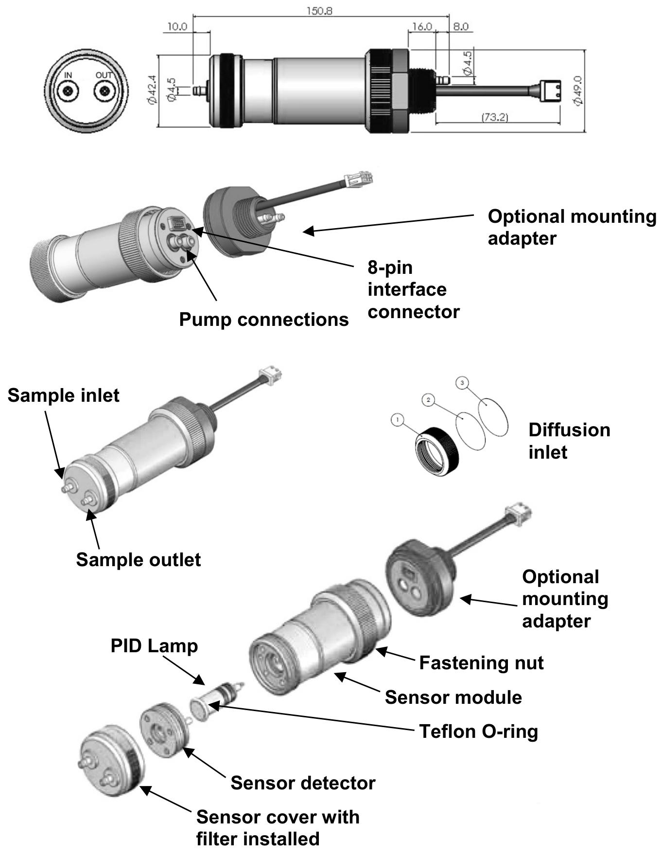
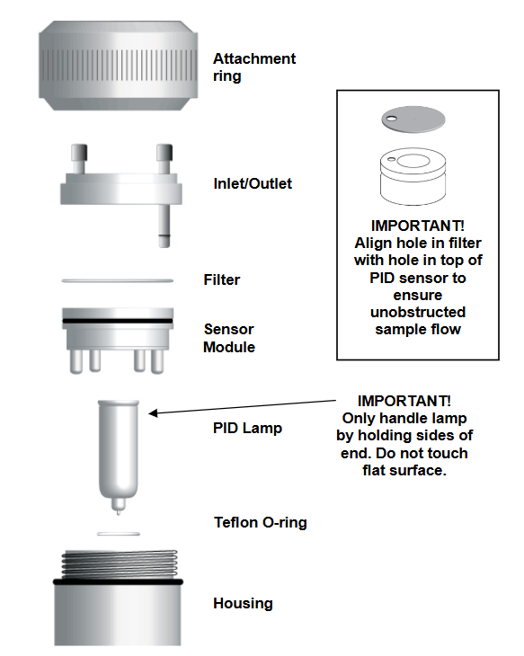
Raeguard 2 PID is a photoionization detection (PID) gas detector launched by Honeywell Analytics, mainly used for detecting volatile organic compounds (VOCs) and other ionizable gases. Its design is suitable for industrial safety, environmental monitoring and other scenarios, with features such as high precision, fast response, and easy installation and maintenance. It can be linked with control systems to achieve real-time monitoring and alarm of gas leaks.
Core functions and features
Detection principle: Using photoionization technology (PID), the energy generated by the ultraviolet lamp ionizes the target gas molecules, and the gas concentration is determined by measuring the ion flow intensity.
Applicable gases: covering most volatile organic compounds (such as benzene, toluene, formaldehyde, etc.) and some inorganic gases (such as ammonia, hydrogen sulfide, etc., to be confirmed according to specific models).
Performance advantages:
Wide range detection (usually 0-1000 ppm or customized range), high resolution;
Fast response and recovery time, suitable for real-time monitoring;
Support multiple output signals (such as 4-20 mA analog, relay alarm, RS485 digital communication, etc.) for easy system integration;
Built in self diagnostic function, which can monitor sensor status, circuit faults, etc., to ensure operational reliability.
Installation and setup
1. Installation preparation
Installation environment: Avoid direct exposure to extreme temperatures (usually operating at -20 ° C to+50 ° C), high humidity, dust, or corrosive gases; Stay away from strong electromagnetic interference sources such as motors and transformers.
Installation position: Select the installation height based on the specific gravity of the detected gas (heavier/lighter than air), ensuring that the sensor probe is located in an area where gas is prone to accumulate; Need to reserve maintenance space (such as replacing sensors, calibrating operations).
2. Wiring and Connection
Power wiring: Usually powered by 24V DC, attention should be paid to positive and negative polarity;
Signal wiring: Connect to the controller, PLC, or alarm system according to the output type (e.g. 4-20 mA signal lines need to be shielded and grounded to avoid interference);
Terminal block instructions: including interfaces for power supply, signal output, alarm relay, etc., corresponding connections should be made according to the manual markings.
3. Initial setup
After power on, wait for preheating (usually a few minutes) to complete sensor stabilization;
Set alarm threshold (low alarm, high alarm), range, unit (ppm or mg/m ³) and other parameters through buttons or supporting software.
Operation and daily maintenance
1. Normal operation
Operation status indication: Check the device status through LED lights (such as green constant light indicating normal, red flashing indicating alarm, yellow indicating fault) or display screen (if any);
Data reading: transmit the output signal to the control system or view the display screen on site (supported by some models).
2. Calibration and verification
Calibration cycle: It is recommended to calibrate regularly (usually every 6 months) according to the usage environment to ensure detection accuracy;
Calibration steps:
Introduce zero air (such as clean air) for zero calibration;
Perform span calibration by introducing a standard gas of known concentration;
Verify the accuracy of the readings after calibration is completed.
3. Maintenance and upkeep
Sensor maintenance: Regularly check the cleanliness of the sensor, and if the probe is contaminated, use specialized tools to clean it; Sensors have a service life (usually 1-2 years) and need to be replaced upon expiration;
UV lamp maintenance: PID core components need to be replaced regularly (usually 1-2 years) according to manual requirements to avoid detection drift caused by lamp aging;
Shell and interface: Regularly check the sealing of the shell (protection level is usually IP66/IP67) to ensure that the wiring terminals are not corroded or loose.
Troubleshooting
Common faults and solutions (speculation):
No output signal: Check if the power supply is normal, if the wiring is loose, and if the fuse is blown;
Reading drift/inaccuracy: perform calibration; Check whether the sensor is expired or contaminated; Confirm the status of the UV lamp;
False alarm: Check for interfering gases (such as high concentration non target VOCs), calibration failure, or environmental humidity/temperature exceeding the range;
Fault light on: Read the fault code through the device’s self diagnostic function or connection software, and troubleshoot the corresponding manual (such as sensor faults, circuit problems, etc.).
Safety and Compliance
Installation and maintenance should be carried out by professional personnel to avoid live working in explosive environments;
Must comply with relevant safety standards (such as ATEX, UL, IEC, etc., depending on the region and model);
Abandoned equipment should be disposed of in accordance with local environmental regulations to avoid environmental pollution caused by sensors or electronic components.
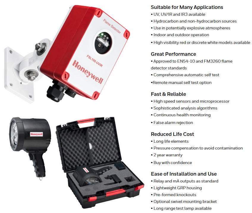
The Honeywell FSL100 series flame detector includes three types: UV, UV/IR, and IR3, with powerful, fast, and reliable flame detection capabilities, suitable for a variety of scenarios. Its design is compact and lightweight, easy to install, and can work in harsh indoor and outdoor environments as well as potentially explosive atmospheres. Through precise sensing and signal analysis technology, it achieves rapid fire detection and effectively reduces false alarms.
Core advantages
Wide applicability: covering UV, UV/IR, IR3 types, capable of detecting various sources of fire such as hydrocarbons and non hydrocarbons, suitable for potential explosive environments and indoor and outdoor scenes, providing high visibility red or low profile white models.
Excellent performance: Complies with EN54-10 and FM3260 flame detector standards, with comprehensive automatic self checking function and supports remote manual self checking options.
Fast and reliable: Using high-speed sensors and microprocessors, combined with complex analysis algorithms, continuous health monitoring is carried out to effectively suppress false alarms.
Reduce lifecycle costs: The components have a long lifespan, have pressure compensation function to avoid pollution, and provide a 2-year warranty.
Easy to install and use: Comes with standard relays and milliampere output, featuring a lightweight glass fiber reinforced plastic (GRP) housing, pre molded knockout design, optional rotating mounting bracket, and long-distance test light.
Characteristics of each model
FSL100-UV:
Suitable for indoor scenarios such as fume hoods and hydrogen storage areas.
Good detection effect on low-temperature combustion substances (such as sulfur).
Can detect heavy hydrocarbons (wood, paper, petroleum, etc.), light hydrocarbons (methanol, methane, etc.), and hydrogen fires.
Has good resistance to artificial light sources such as direct/reflected sunlight, fluorescent lamps, and glass covered halogen lamps.
FSL100-UV/IR:
Improve false alarm suppression capability by analyzing flame flicker frequency.
The dual sensing method can effectively detect various hydrocarbon and non hydrocarbon fires.
Has good resistance to sunlight, artificial light sources, electric arcs and discharges (generated by static electricity or motors), and welding radiation at a distance of more than 10 feet.
FSL100-IR3:
Analyze flame flicker frequency to reduce false alarms, especially suitable for liquid hydrocarbon fires and smoke fires.
Less affected by window pollution or smoke.
The anti-interference ability is similar to UV/IR, especially suitable for fire scenarios with high smoke levels.
Applicable scenarios
It covers various scenarios such as aircraft hangars, atriums, battery storage rooms, biogas facilities, parking lots, clean rooms, CNG refueling stations, cold storage, engine rooms, laboratories, loading and unloading docks, oil and gas pipeline pump stations, outdoor storage areas, etc. Different models have slightly different applicable scenarios (please refer to the application table in the document for details).
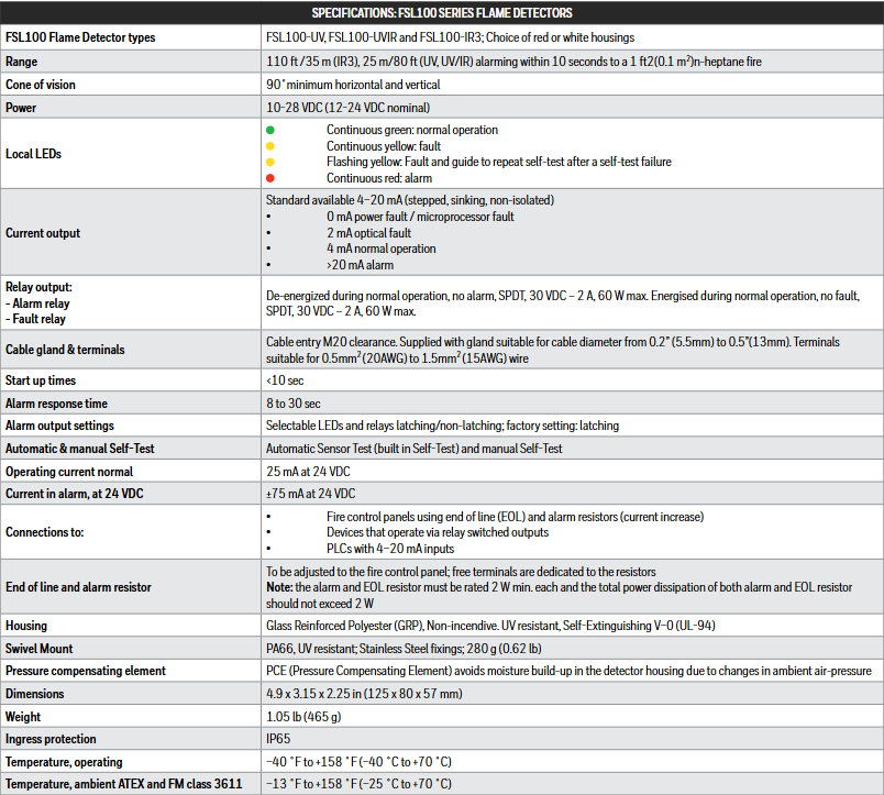
General Technical Specifications
Parameter details
Model types FSL100-UV, FSL100-UVIR, FSL100-IR3, optional red or white casing
The detection range is IR3 at 110 feet/35 meters, UV and UV/IR at 25 meters/80 feet (for 1 square foot n-heptane fire, an alarm will be triggered within 10 seconds)
Field of view with a minimum horizontal and vertical angle of 90 °
Power supply 10-28 VDC (nominal 12-24 VDC)
The local LED indicates green constant light (normal operation), yellow constant light (fault), yellow flashing (repeat self-test after self-test failure), and red constant light (alarm)
Current output standard 4-20 mA (step, sinking, non isolated), 0 mA (power/microprocessor failure), 2 mA (optical failure), 4 mA (normal),>20 mA (alarm)
Relay output alarm relay (normally powered off, SPDT, 30 VDC-2A, maximum 60 W); Fault relay (powered normally, SPDT, parameters the same as alarm relay)
Cable gland and terminal M20 cable entry, compatible with 0.2-0.5 inch (5.5-13mm) cables; Terminal compatible with 0.5mm ² (20AWG) to 1.5mm ² (15AWG) wires
Start time<10 seconds
Alarm response time 8-30 seconds
Self checking function: automatic sensor testing and manual self checking
When the working current is normal, it is 25 mA (24 VDC); ± 75 mA (24 VDC) during alarm
Normal operating temperature: -40 ° F to 158 ° F (-40 ° C to 70 ° C); ATEX and FM 3611 levels: -13 ° F to 158 ° F (-25 ° C to 70 ° C)
Size and weight 4.9 x 3.15 x 2.25 inches (125 x 80 x 57 mm), weight 1.05 pounds (465 g)
Other information
Can connect fire control panel, relay switch equipment, PLC with 4-20 mA input, etc.
The terminal resistor needs to be compatible with the fire control panel, with a rated power of at least 2 W for alarm and terminal resistors, and a total power consumption not exceeding 2 W.
MC024-010 and MC024-012 are PLUS+1 under Sauer Danfoss ™ Part of the series of mobile machinery management products, it belongs to the universal controller. They are suitable for both distributed machine control systems (where each node has intelligence) and can be used as independent controllers, with characteristics such as flexibility, powerful performance, scalability, and economy.
Product Highlights
MC024-010: Equipped with a digital signal processor (DSP), it has extremely fast single cycle processing speed and built-in 128K flash memory.
MC024-012: Includes application key, compatible with the GUIDE machine control solution developed by Sauer Danfoss.
Two controllers can share the same GUIDE HWD file.
Application development
Users can use Microsoft based ® Windows ® The PLUS+1 GUIDE development environment is used for application development, which features user-friendly and proven icon based graphical programming tools, application downloaders, and service/diagnostic tools.
Main characteristics
Processor and Storage: 32-bit fixed-point DSP, operating at a frequency of 150 MHz.
14 inputs, including 5 universal inputs (can be defined as analog, digital, or frequency inputs), 6 digital inputs, 2 analog inputs (can be used for temperature or rheostat), and 1 fixed range analog input (can be configured as a CAN shield pin).
The analog input range can be configured, the digital input can be configured as pull-up, pull-down, or center pull, and the frequency input range is 1 Hz to 10 kHz.
Output:
Four universal outputs can be defined as digital output (3 A, configurable as source or drain), PWM output (30 to 4000 Hz, configurable as open-loop or closed-loop with current control), or analog voltage output (4000 Hz open-loop PWM).
Any PWM output/digital output/PVGOUT can provide reference power for a PVG valve.
Power and Communication:
9 to 36 Vdc power supply, internal monitoring.
1 CAN 2.0 B port, fixed range analog input can be configured as a shielded pin.
Provide internal regulated power supply of 5 Vdc, 300 mA for external sensors.
Other: 2 user controllable LEDs; 3 installation methods (stacked, end mounted, side mounted); Compliant with CE standards.
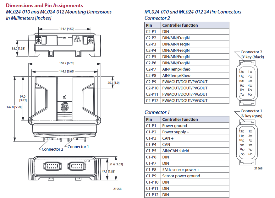
Size and Pin Allocation
Dimensions (millimeters/inches): Some key dimensions include 114.4 [4.50], 35.0 [1.38], 158.2 [6.23], etc. (please refer to the dimension diagram for details).
Pin allocation:
Connector 2 (24 pins): Includes multiple functional pins such as DIN, DIN/AIN/FreqIN, AIN/Temp/Reo, PWMOUT/DOUT/PVGOUT, etc.
Connector 1: Includes power ground, power positive, CAN positive and negative, AIN/CAN shielding DIN、 Sensor power supply and other functional pins.
Attention: This device cannot be repaired on site, opening the casing will void the warranty.
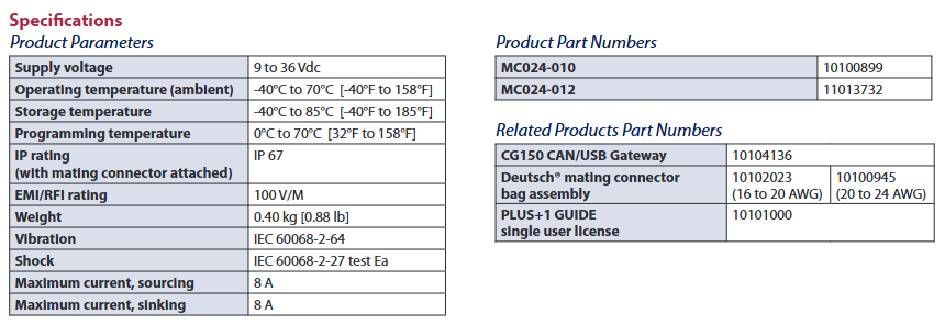
Specification parameters
Supply voltage: 9 to 36 Vdc
Working temperature (environment): -40 ° C to 70 ° C (-40 ° F to 158 ° F)
Storage temperature: -40 ° C to 85 ° C (-40 ° F to 185 ° F)
Programming temperature: 0 ° C to 70 ° C (32 ° F to 158 ° F)
IP rating (with matching connector): IP 67
EMI/RFI level: 100 V/M
Weight: 0.40 kg (0.88 lb)
Vibration: Complies with IEC 60068-2-64
Impact: Complies with IEC 60068-2-27 test Ea
Maximum source current: 8 A
Maximum current: 8 A
Product model and related products
Product model: MC024-010 corresponds to model 10100899; MC024-012 corresponds to model 11013732.
Related products: CG150 CAN/USB gateway Deutsch ® Match connector component (10100945, suitable for 20 to 24 AWG), PLUS+1 GUIDE single user license.