Bently 3500/20 Rack Interface Module
Module Overview
Core functions
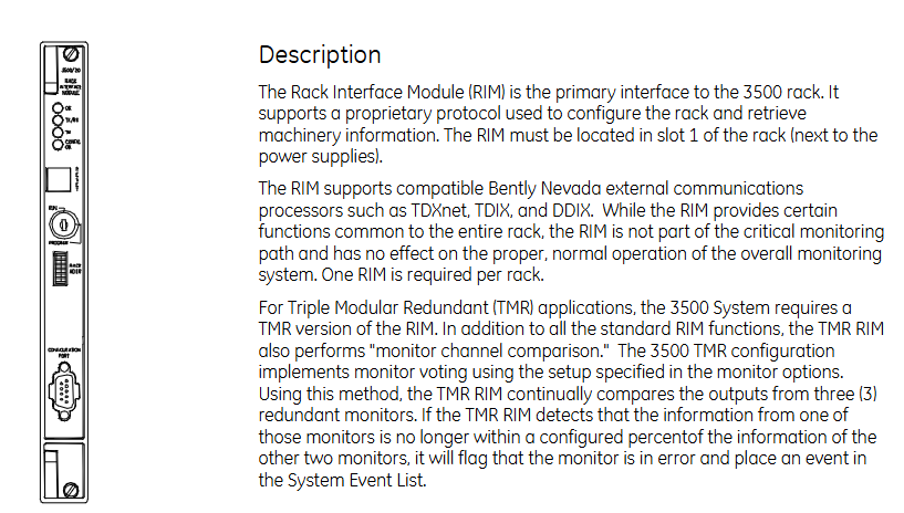
As the main interface of the 3500 rack, it supports proprietary protocols for configuring the rack and obtaining mechanical information, and must be installed in slot 1 of the rack (adjacent to the power supply).
Supports compatible Bently Nevada external communication processors (such as TDXnet, TDIX, DDIX), does not participate in critical monitoring paths, does not affect system normal operation, and requires one per rack.
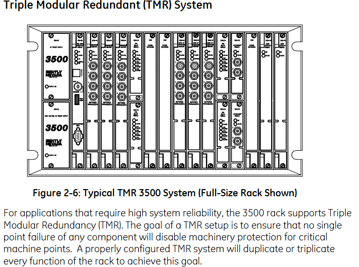
TMR version: For Triple Modular Redundancy (TMR) applications, in addition to standard functions, it can also perform “monitoring channel comparison” – continuously comparing the outputs of three redundant monitors. If the data of one monitor deviates from the other two by more than the configured percentage, an error will be marked and recorded in the system event list.
Technical specifications
input parameter
Power consumption: Typical value of 4.75 watts.
Data interface:
Front panel: Standard RS232 serial communication, speed of 38.4 k baud.
I/O module: Supports RS232/RS422 serial communication (up to 38.4 k baud) and internal modem communication (14.4 k baud).
Output parameters
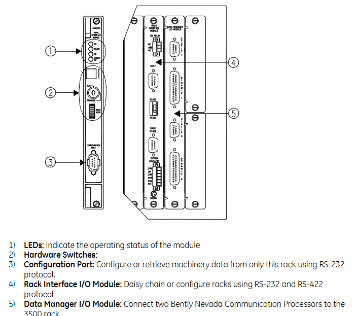
Front panel LED:
OK LED: Indicates that the module is operating normally.
TX/RX LED: Indicates that the module is communicating with other modules inside the rack.
TM LED: Indicates that the rack is in the “Trip Multiply” state.
CONFIG OK LED: Indicates that the rack configuration is valid.
I/O module OK relay: used to indicate the normal operation or fault of the rack, with the option to select the “open” or “close” contact annunciate fault state, normally excited operation, rated value 5A @ 24Vdc/120Vac (120W/600VA), equipped with an arc extinguisher, normally closed contact.
Control components
Front panel reset button: clears the lock alarm and timed OK channel failure inside the rack, with the same function as the “Rack Reset” contact on the I/O module.
Address switch: Set the rack address to a maximum of 63 addresses.
Configure key lock: Switch the rack to “RUN” mode (normal operation, locking configuration changes) or “GRAM” mode (allowing local/remote configuration), the key can be removed from any position, RUN mode restricts unauthorized reconfiguration, and GRAM mode supports remote configuration at any time.
Communication and Interface
I/O module system contacts
Including Trip Multiply (to put the rack into Trip Multiply state), Alarm inhibit (to suppress all alarms), Rack reset (to clear lock alarms, etc.), maximum current<1mA dc (from dry contact to common terminal).
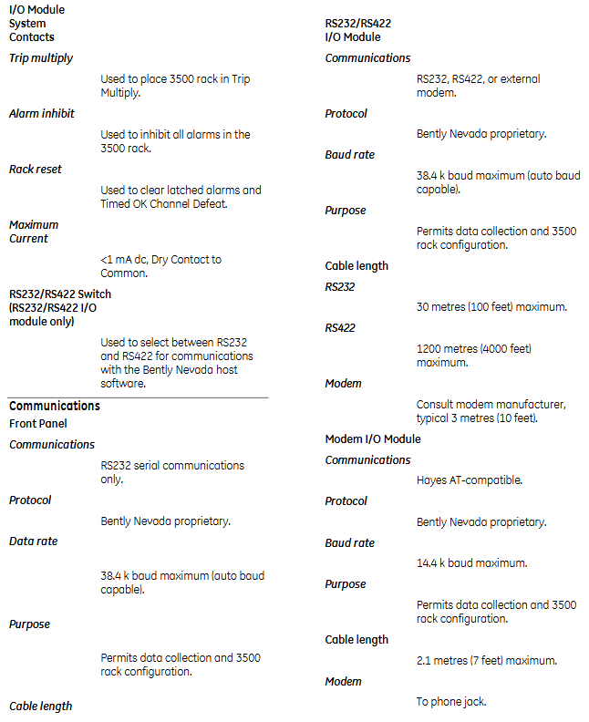
Communication interface details
Interface type, communication protocol, rate usage, maximum cable length
Front panel RS232 Bently Nevada proprietary maximum 38.4 k baud (supports automatic baud rate) data collection and rack configuration 30 meters (100 feet)
RS232/RS422 I/O module Bently Nevada proprietary communication with host software up to 38.4 k baud RS232: 30 meters; RS422: 1200 meters (4000 feet)
The I/O module of the modem is Hayes AT compatible, with a proprietary protocol of up to 14.4 k baud for data collection and rack configuration. It is 2.1 meters (7 feet, up to the telephone jack) long
Rack connector RS422 Bently Nevada proprietary maximum 38.4 k baud multi rack Daisy choked communication 1200 meters
Data Manager I/O Module (2 sets of ports) Bently Nevada proprietary fixed 9600 baud static and dynamic data collection 3 meters (10 feet)
Environmental and physical parameters
Environmental limitations
Rack interface module and RS232/RS422 I/O: operating temperature -30 ° C to+65 ° C, storage temperature -40 ° C to+85 ° C; modem I/O module: operating temperature 0 ° C to+50 ° C, storage temperature -40 ° C to+85 ° C.
Humidity: 95% non condensing.
CE certification: Complies with EMC directives (EN50081-2, EN55011, etc.) and low voltage directives (EN 61010-1).
Hazardous Area Certification: CSA/NRTL/C Class I, Div 2, Groups A, B, C, D, T4 @ Ta=-20 ° C to+65 ° C.
Physical specifications
RIM dimensions: 241.3mm x 24.4mm x 241.8mm (height x width x depth), weight 0.91kg.
RS232/RS422 I/O、 Modems I/O and Data Manager I/O modules: size 241.3mm × 24.4mm × 99.1mm, weight 0.45kg.
Rack space requirement: RIM motherboard occupies one full height front slot; The RIM I/O module and the Data Manager I/O module each occupy one full height rear slot.
Order Information
Module model: 3500/20-AXX-BXX-CXX
A (interface type): 01=standard RIM, 02=TMR RIM (only for TMR configuration).
B (I/O module type): 01=with built-in modem, 02=with RS232/RS422 interface.
C (institutional certification): 00=none.
Spare parts and cables
Spare parts include standard/TMR RIM, various I/O modules, grounding wristbands, firmware ICs, etc.
There are various types of cables, including interfaces (RS232/RS422), lengths (10 feet to 500 feet+), and insulation materials (PVC/Teflon) ®) And assembly status classification, supporting connections between hosts and racks, and between racks. Expansion cables can be used for distances exceeding 500 feet.