Bently 3500/15 AC/DC power module
Product Overview
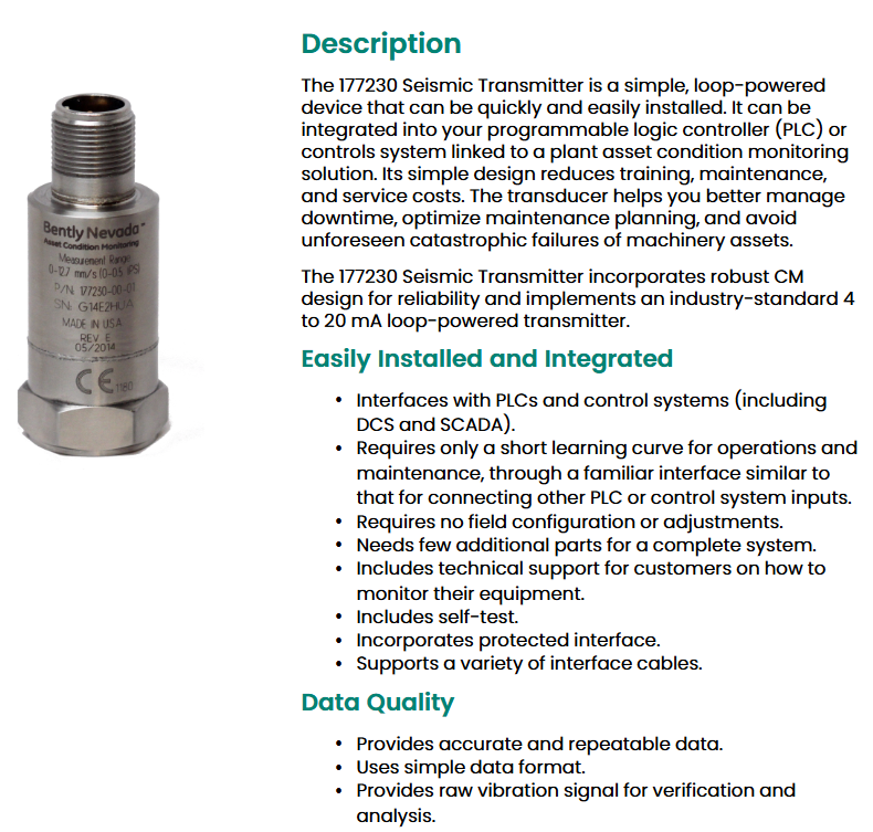
Core functions and applications
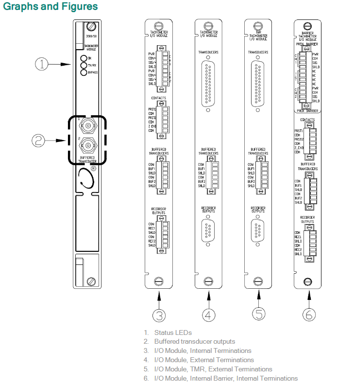
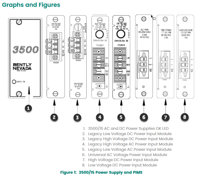
The 3500/15 AC/DC power module is a half height module that must be installed in the designated slot on the left side of the rack to provide power to other modules of the 3500 series mechanical protection system. The rack can accommodate one or two power modules (any combination of AC and DC), and a single power supply can power the entire rack.
In the dual power supply configuration, the lower slot is the primary power supply and the upper slot is the standby power supply. It supports hot plugging (removing or inserting any module will not affect the rack operation).
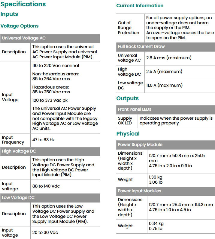
Supports a wide range of input voltages and converts them into voltages that can be used by other 3500 modules, including three types: universal AC power supply, high-voltage DC power supply, and low-voltage DC power supply.
Technical specifications
1. Input parameters
Universal AC power supply: Non hazardous area: 85-264 Vac rms;
Dangerous area: 85-250 Vac rms (peak 120-373 Vac) 47-63 Hz 2.8 A rms
High voltage DC power supply: 88-140 Vdc -2.5 A
Low voltage DC power supply: 20-30 Vdc -11.0 A
Protection function: Under voltage will not damage the power supply or PIM (power input module); Overvoltage can cause the fuse on PIM to melt.
2. Physical and installation parameters
Power module:
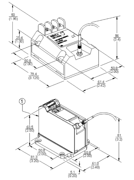
Dimensions: 120.7 mm x 50.8 mm x 251.5 mm (height x width x depth), weight 1.39 kg.
Power Input Module (PIM):
Dimensions: 120.7 mm x 25.4 mm x 114.3 mm (height x width x depth), weight 0.34 kg.
Rack space requirements:
Power module: occupying two half height slots on the left side of the rack, supporting redundant configuration.
PIM: A dedicated half height module located directly behind the corresponding power module.
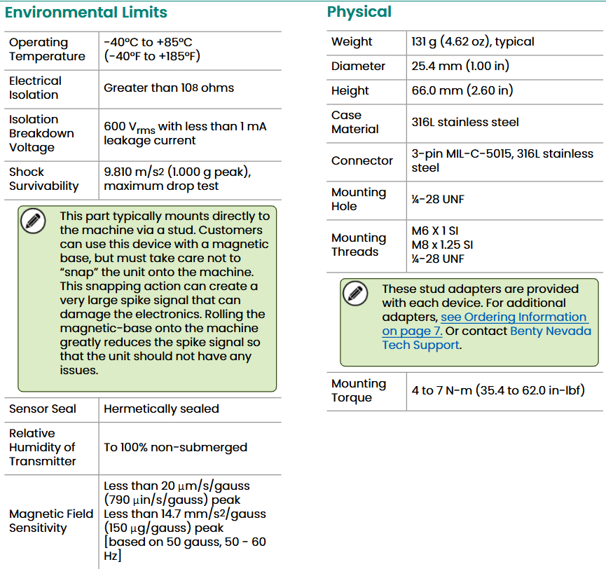
3. Environmental parameters
Working temperature: -30 ° C to+65 ° C (-22 ° F to+150 ° F).
Storage temperature: -40 ° C to+85 ° C (-40 ° F to+185 ° F).
Humidity: 95% non condensing.
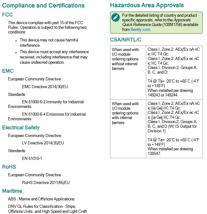
Compliance and Certification
FCC: Complies with Part 15 of FCC regulations, does not cause harmful interference, and is tolerant of external interference.
EMC: Compliant with EMC Directive 2014/30/EU and EN 61000-6-2 (industrial immunity), EN 61000-6-4 (industrial emission limits) standards.
Electrical safety: complies with the Low Voltage Directive 2014/35/EU and EN 61010-1 standards.
RoHS: Compliant with RoHS Directive 2011/65/EU, restricting the use of hazardous substances.
Maritime certification: Complies with DNV GL ship, offshore platform, and high-speed light vessel specifications, ABS steel ship and marine structure classification rules.
Hazardous Area Certification:
cNRTLus:Class I, Zone 2/Division 2,Groups A-D, T4@Ta -Install according to drawing 149243/149244 for temperatures between 20 ° C and+65 ° C.
ATEX/IECEx:II 3 G Ex nA nC ic IIC T4 Gc/Ex ec nC ic IIC T4 Gc, T4@Ta -20 ° C to+65 ° C.
Order Information
1. Rules for power module model
The complete model of the 3500/15 power module is 3500/15-AA-BB-CC, and the meanings of each parameter are as follows:
AA (Top Slot Power Type)
03: Traditional High Voltage DC Power Supply (88-140 Vdc)
04: Traditional low-voltage DC power supply (20-30 Vdc)
05: Universal AC power supply (85-264 Vac rms)
06: High voltage DC power supply (new specification)
07: Low voltage DC power supply (new specification)
BB (bottom slot power type)
00: No power supply (choose when bottom slot power supply is not required)
03/04/05/06/07: Same as the top slot, corresponding to traditional/new specifications of high and low voltage DC, universal AC power supply
CC (authentication option)
00: No authentication
01: CSA/NRTL/C certification (applicable to Class I, Division 2 hazardous areas)
02: ATEX/IECEx/CSA certification (applicable to Class I, Zone 2 hazardous areas)
Spare parts list
1. Power module and input module (PIM)
106M1079-01: Universal AC power module
106M1081-01: Universal AC Power Input Module (PIM)
129486-01: Traditional High Voltage DC Power Supply Module (88-140 Vdc)
129478-01: Traditional High Voltage DC Power Input Module (PIM)
133292-01: Traditional Low Voltage DC Power Supply Module (20-30 Vdc)
133300-01: Traditional Low Voltage DC Power Input Module (PIM)
114M5329-01: New specification high-voltage DC power module
115M7750-01: New Specification High Voltage DC Power Input Module (PIM)
114M5330-01: New specification low-voltage DC power module
114M5335-01: New Specification Low Voltage DC Power Input Module (PIM)
2. Fuses and connectors
01720025: Replace fuses (applicable to AC PIM and traditional high-voltage DC PIM)
01720045: Replace fuse (applicable to low voltage DC PIM and traditional low voltage DC PIM)
120M3877: Quick melting fuse (5A/500 Vac, 6.3 × 32 mm, universal AC PIM specific)
129M0198: New specification of high-voltage DC PIM dedicated replacement fuse
118M0915-01: Replacement connector for universal AC power input module
118M0915-02: Replacement connector for DC power input module
3. Panel and installation accessories
131150-01: Blank front panel of power module (including screws, 1 piece)
128085-01: Power input connector back cover (1 piece)
04310251: Power input back cover fixing screws (2 pieces)
284726: DIN rail mounting kit (for power module rack installation)