Call us 24/7uaedcs@163.com
Welcome to the official website of CNIACS Automation Technology Co., Ltd!
Call us 24/7uaedcs@163.com

Eckardt SRI986 Intelligent Valve Positioner

Eckardt SRI986 is an intelligent electrical valve positioner launched by the Eckardt brand under Emerson. It is designed specifically for pneumatic actuators in industrial process control and achieves high-precision adjustment of valve opening through precise electrical pneumatic signal conversion and closed-loop control. This product integrates non-contact position detection, modular structure, and intelligent diagnostic functions, and is compatible with industrial communication protocols such as HART and PROFIBUS PA. It is widely used in industries such as petrochemicals, power, water treatment, and pharmaceuticals, and is suitable for both linear and rotary pneumatic actuators. Its core advantages lie in high adjustment accuracy, low maintenance requirements, and strong environmental adaptability.

Core positioning and technological advantages of the product

1. Core functions and applicable scenarios

High precision positioning control: using non-contact Hall effect position sensors, the adjustment accuracy reaches ± 0.5% of the full range (Span), and the repeatability accuracy is ± 0.1%. It is suitable for scenarios that require strict flow/pressure control, such as chemical reactor feed valves and power plant steam control valves.

Intelligent diagnosis and communication: Supports HART 7.0 (standard) and PROFIBUS PA (optional) protocols, and can remotely read valve operation data (such as opening, gas supply pressure, fault codes) through a handheld device (such as Rosemount 475) or control system to achieve predictive maintenance.

Wide range adaptation: compatible with single acting (Spring Return) and double acting (Double Acting) pneumatic actuators, with a gas source pressure range of 0.2-1.0 MPa (2-10 bar), and output force/torque covering multiple actuator specifications (maximum linear thrust of 40 kN, maximum angular torque of 500 N · m).

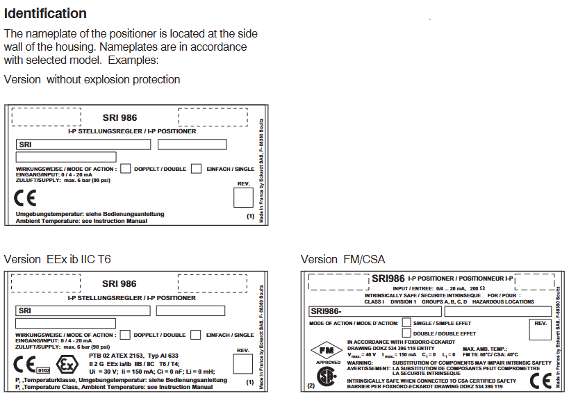
Environmental tolerance: Protection level IP66/IP67 (standard), IP68 (optional), temperature range -40~+85 ℃ (conventional), -55~+100 ℃ (high temperature option), certified by ATEX, IECEx, CSA and other explosion-proof certifications, can be used in Zone 1/2 (Class I hazardous areas) and corrosive environments (optional corrosion-resistant coating).

2. Key technological highlights

Non contact position detection: Abandoning traditional mechanical linkage detection, adopting Hall sensor+magnetic ring structure, no mechanical wear, with a lifespan of over 1 million cycles, reducing maintenance frequency.

Adaptive control algorithm: Built in “Auto Tune” function, automatically recognizes the characteristics of the actuator (such as stroke and response speed) after power on, optimizes PID control parameters, eliminates the need for manual debugging, and shortens installation time.

Modular design: divided into control unit (electronic module), pneumatic module (solenoid valve+air circuit) and connecting components, each module is independently disassembled and can be replaced separately in case of failure, reducing maintenance costs and downtime.

Hardware structure and technical specifications

1. Core components and functions

Component Category Key Component Function Description

Electronic control unit Hall position sensor, microprocessor, communication chip 1. Receive 4-20mA/HART/PROFIBUS PA input signals;

2. Check the actual position of the valve (resolution 0.01% of full range);

3. Execute PID control algorithm and output control signal to pneumatic module;

4. Store operational data and diagnostic information, and support remote communication.

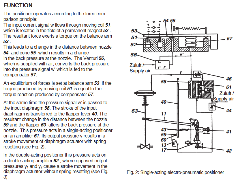
Pneumatic module piezoelectric valve, pressure sensor, pneumatic block 1. Convert electronic signals into pneumatic signals (output pressure 0.2-1.0 MPa);

2. Single acting mechanism: controls the “on/off” side pressure (spring reset);

3. Double acting mechanism: independently controls the pressure on both sides of “on” and “off”;

4. Built in pressure sensor, real-time monitoring of gas supply and output pressure.

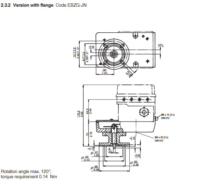
Connecting and installing component brackets, connecting shafts, explosion-proof enclosures. 1. The bracket is compatible with straight stroke (ISO 5211 standard flange) and angular stroke (shaft diameter 10-30mm) actuators;

2. The connecting shaft supports ± 5 ° angle deviation compensation, simplifying installation alignment requirements;

3. The shell is made of aluminum alloy (conventional) or stainless steel (corrosion-resistant option), with an explosion-proof rating of Ex d IIC T6 (ATEX).

2. Key technical parameters

(1) Control performance

Parameter linear actuator angular actuator

Travel range 2-100 mm (standard), 100-300 mm (extended), 0-90 ° (standard), 0-180 °/0-360 ° (optional)

Adjustment accuracy ± 0.5% full range ± 0.5% full range

Response time ≤ 0.3 seconds (step signal 10% -90%) ≤ 0.5 seconds (step signal 10% -90%)

Dead zone ≤ 0.1% of full range (adjustable through software) ≤ 0.1% of full range

(2) Electrical and Pneumatic Parameters

Input signal:

Standard: 4-20 mA DC (load resistance 250-600 Ω)+HART 7.0;

Optional: PROFIBUS PA (IEC 61158-2, transmission rate 31.25 kbps).

Power requirements:

HART version: 12-30 V DC (typical power consumption 1.5 W);

PROFIBUS PA version: 9-32 V DC (compliant with IEC 61158-3 power supply standard).

Gas source requirements:

Pressure: 0.2-1.0 MPa (clean and dry compressed air, filtration accuracy ≤ 5 μ m, dew point 10 ℃ lower than ambient temperature);

Gas consumption: Double acting ≤ 0.3 Nm ³/h (steady state), single acting ≤ 0.2 Nm ³/h (steady state).

(3) Environment and Certification

Protection level: IP66 (dustproof and waterproof), IP67 (short-term immersion), IP68 (long-term immersion, optional);

Temperature range: -40~+85 ℃ (conventional), -55~+100 ℃ (high temperature option), -20~+60 ℃ (intrinsic safety version);

Explosion proof certification:

ATEX:Ex d IIC T6 Ga(Zone 1)、Ex nA IIC T6 Gc(Zone 2);

IECEx:Ex d IIC T6 Ga、Ex nA IIC T6 Gc;

CSA:Class I Div 1/2,Groups A-D,T6。

Operation and configuration process

1. Installation and initialization

(1) Mechanical installation

Bracket fixation: Select the corresponding bracket according to the type of actuator (straight stroke/angular stroke), and fix the locator with ISO 5211 flange (straight stroke) or shaft sleeve (angular stroke) to ensure that the connecting shaft is coaxial with the actuator shaft (deviation ≤ 5 °).

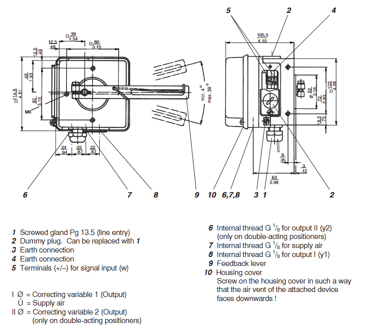
Air source connection: Connect clean compressed air to the “Supply” port (G1/4 thread) of the locator. Single acting mechanisms need to distinguish between “Output” (working side) and “Exhaust” (exhaust side), while double acting mechanisms need to distinguish between “Open” and “Close” ports.

Electrical wiring: The HART version is connected to a 12-30 V DC power supply and a 4-20 mA signal (two-wire system); The PROFIBUS PA version is connected to the bus power and signal lines (two-wire system), and the wiring terminals must meet explosion-proof sealing requirements (such as using explosion-proof gland heads).

(2) Auto Tune

Starting conditions: Ensure that the air source pressure is normal (0.2-1.0 MPa), the actuator is not stuck, and the locator is powered on (power light is always on).

Trigger self-tuning:

Local: Long press the “Auto Tune” button on the locator (3 seconds), the indicator light will flash (red), and enter self-tuning mode;

Remote: Send the “Auto Tune” command through a HART controller or control system.

Process and completion: The locator automatically drives the actuator to run throughout the entire stroke (2-3 times), records parameters such as stroke time and response characteristics, and optimizes PID parameters; After the self-tuning is completed, the indicator light turns green and stays on, and the system enters normal control mode.

2. Daily operations and diagnosis

(1) Local operation

Status indication: Judging the operating status through 3 LED lights——

Green constantly on: normal operation; Green flashing: self-tuning in progress;

Yellow constantly on: warning (such as low gas supply pressure, slight jamming); Yellow flashing: communication failure;

Red constantly on: serious malfunction (such as position sensor failure, actuator jamming); Red flashing: Over range alarm.

Manual adjustment: Long press the “Manual” button (3 seconds) to enter manual mode, adjust the valve opening through the “Up”/”Down” buttons, and release the button for 5 seconds to automatically return to automatic mode (to prevent misoperation).

(2) Remote diagnosis (HART/PROFIBUS PA)

The following key data and diagnostic information can be read through a handheld device or control system:

Operating data: actual valve opening (%), set value (%), supply pressure (MPa), output pressure (MPa), working temperature (℃);

Diagnostic information:

Mild malfunction: low gas supply pressure (<0.2 MPa), slow response of the actuator (jamming warning);

Severe faults: position sensor failure, piezoelectric valve failure, communication interruption;

Maintenance tips: valve action frequency (cumulative), last maintenance time, recommended maintenance cycle (such as checking the air circuit every 100000 actions).

Configuration options and ordering information

1. Core configuration options

Applicable scenarios for configuring category options

Communication protocol HART 7.0 (standard), PROFIBUS PA (optional) HART: for small and medium-sized systems, low cost; PROFIBUS PA: A large-scale bus system that requires multiple devices to be networked

Type of actuator: Linear, Rotary. Linear: Globe valve, gate valve; Angular stroke: butterfly valve, ball valve

Explosion proof rating Ex d IIC T6 (standard), Ex ia IIC T4 (intrinsic safety, optional) Ex d: Zone 1/2, suitable for high-risk areas; Ex ia:Zone 0/1, Suitable for extremely high-risk areas

Protection level IP66/IP67 (standard), IP68 (optional, water depth 1m/24h) IP68: humid environment (such as sewage treatment plant, outdoor during rainy season)

Materials and coatings: Aluminum alloy shell (conventional), stainless steel shell (optional), corrosion-resistant coating (PTFE, optional) Stainless steel+PTFE: corrosive environment (such as chemical acid/alkali gas)

2. Typical ordering models

Eckardt SRI986 model coding rule: SRI986- [Protocol] – [Type of actuator] – [Explosion proof level] – [Protection level], example as follows:

SRI986-H-LD-67: HART protocol, linear actuator, Ex d explosion-proof, IP67 protection;

SRI986-P-R-IA-68: PROFIBUS PA protocol, angular actuator, Ex ia intrinsic safety, IP68 protection;

SRI986-H-R-D-66: HART protocol, angular travel actuator, Ex d explosion-proof, IP66 protection (standard selection).

3. Common accessories

Installation accessories: Straight stroke bracket (SRI986Mount-L), angular stroke shaft sleeve (SRI986-Shift-R-20mm), explosion-proof gland head (M20, Ex d certified);

Maintenance accessories: piezoelectric valve spare parts (SRI986-Piezo-01), air filter (precision 5 μ m, with drainage), HART handheld controller (Rosemount 475);

Calibration tools: SRI986 Calibrator, pressure sensor calibration kit.

Application scenarios and core values

1. Typical application areas

Petrochemical industry: The feed control valve of the catalytic cracking unit and the reflux valve of the fractionation tower are controlled with high precision (± 0.5%) to ensure stable reaction temperature and pressure, avoiding the risk of overheating and overpressure;

Power industry: steam regulating valves for steam turbines in thermal power plants, outlet valves for cooling water pumps in nuclear power plants, suitable for high temperature environments (+85 ℃) and explosion-proof requirements, supporting PROFIBUS PA bus integration into DCS systems;

Water treatment: Water treatment plant dosing valve, sewage treatment plant aeration valve, IP68 protection suitable for humid environments, self-tuning function simplifies on-site debugging;

Pharmaceutical industry: mixing speed control valve for drug reaction kettle, flow valve for sterile filling line, stainless steel shell+PTFE coating to meet corrosion resistance and hygiene requirements, intelligent diagnosis to reduce unplanned downtime.

2. Core user value

Improve control accuracy: ± 0.5% adjustment accuracy reduces process fluctuations and enhances product qualification rate (such as chemical product purity and drug dosage accuracy);

Reduce maintenance costs: Non contact sensors have no wear and tear, modular design simplifies maintenance, predictive diagnosis provides early warning of faults, and reduces downtime (MTBF increases by more than 30%);

Simplified integration and debugging: compatible with mainstream communication protocols, self-tuning function does not require professional personnel, shortening project deployment cycle (reducing debugging time by 50%);

Adapt to harsh environments: wide temperature range, high protection, explosion-proof design, covering the vast majority of harsh working conditions in industrial sites, without the need for additional protective measures.

Maintenance and Precautions

Regular maintenance:

Every 3 months: Check the air source pressure and filter (clean impurities, drain water);

Every 6 months: calibrate the accuracy of the locator (perform “accuracy calibration” through a HART handheld device), and check the looseness of the connecting shaft;

Every year: Replace the air filter element and check the response performance of the piezoelectric valve (through diagnostic function).

Fault handling:

Low gas supply pressure: Check the pressure of the air compressor and clean the filter;

Position sensor malfunction: Check if the magnetic ring has come off and replace the sensor module;

Communication interruption: Check the wiring terminals to confirm that there is no short circuit or grounding on the HART/PROFIBUS PA bus.

Safety regulations:

Power off is required for maintenance in explosion-proof areas, explosion-proof tools should be used, and live disassembly and assembly are strictly prohibited;

The intrinsic safety version (Ex ia) must ensure that the bus power supply complies with the IEC 61158-3 standard to avoid excessive power supply;

Calibration and maintenance must be carried out by Eckardt certified engineers, using original spare parts to avoid affecting explosion-proof and precision performance.

Honeywell System 57 5704 Control System

The Honeywell System 57 5704 control system is a modular control platform designed specifically for industrial gas detection under Honeywell. It is mainly used to monitor gas detectors installed on site, achieve multi-channel gas concentration monitoring, alarm triggering, and remote control functions. This system has the core advantages of high reliability, flexible scalability, and strict safety compliance, and is widely used in industrial scenarios such as petrochemicals, chemical engineering, pharmaceuticals, and power that require strict gas leak detection. It can be adapted to various types of gas sensors such as catalytic combustion and 4-20mA.

System core positioning and security standards

1. Core functions and scope of application

Multi channel monitoring capability: The standard 19 inch 3U rack can support up to 64 channels of gas detection (4 channels per card), and the half 19 inch 3U rack can support up to 32 channels, adapting to the distributed monitoring needs of large-scale industrial sites.

Sensor compatibility: Supports two types of core sensor inputs – catalytic combustion sensors (for combustible gas detection) and 4-20mA signal sensors (for toxic gas, oxygen, etc. detection), meeting the monitoring needs of different gas types.

Alarm and Control: Provides multi-level alarms (A1/A2/A3 three-level concentration alarm, STEL short-term exposure limit alarm, LTEL long-term exposure limit alarm), fault alarms (sensor faults, line faults), and suppression alarms, supports relay output, analog output (0-20mA/4-20mA), and can be linked to external devices (such as exhaust systems, sound and light alarms).

2. Safety and compliance requirements

Environmental restrictions: Non explosion proof design, only applicable to safe areas (non hazardous areas), and limited to indoor use only. Exposure to rainwater or humid environments is prohibited.

Operating standards: Installation, calibration, and maintenance must be carried out by professionals, and only Honeywell certified accessories are allowed to be used to avoid safety risks caused by unauthorized replacement of components.

Compliance standards: Compliant with the EU ATEX Directive (EC Type Examination Certificate BVS 04 ATEX G 001 X), EN 50073 (Specification for Selection and Maintenance of Gas Detection Equipment), EN 60079-14 (Standard for Electrical Installation in Hazardous Areas), etc. Electromagnetic compatibility (EMC) meets the EN 61000-6 series standards, and the ability to resist radio frequency interference (RFI) reaches 10V/m (27-1000MHz).

System hardware composition and module functions

The 5704 control system adopts a modular design, with core components including control cards, interface cards, engineering cards, power modules, and racks/cabinets. Each module has clear functions and can be flexibly combined

1. Core functional modules

Module Name Model Example Core Function Key Parameters

Four channel control card 05704-A-0144 (catalytic input)

05704-A-0145 (4-20mA input) sensor signal processing, concentration display, alarm logic judgment, 4 channels per card; The catalytic card supports constant current drive of 90-315mA; 4-20mA card supports 0-25mA signal measurement

The four relay interface card 05704-A-0121 provides a wiring interface for sensors and control systems, providing four relay outputs (single pole double throw) with a rated current of 5A (110/250V AC or 32V DC) for relay contacts; Supports 2.5mm ² (14 AWG) wire connection

Relay expansion component 05704-A-0131 (interface card+expansion card) expands the number of relays to 16 (12 single pole double throw+4 single pole single throw), adapting to complex alarm linkage requirements and occupying 2 rack slots; Extra weight of 0.5kg, requires separate power supply

The core operating interface for system configuration, calibration, and diagnosis of engineering card 05701-A-0361 provides RS232 interface for connecting to PC or printer to support parameter adjustment (such as alarm threshold, sensor current), fault diagnosis, and maintenance record printing; Engineering key is required to unlock advanced features

DC input card 05701-A-0325 system power access and distribution, supports dual power input (main power+backup battery), provides overcurrent protection input voltage 18-32V DC; Built in 10A anti surge fuse; Support power diode isolation to avoid power conflicts

AC-DC power module 05701-A-0405 (16 channels)

05701-A-0406 (8-way) converts 85-264V AC to 24V DC system power supply, supports power upgrade (50W → 200W), 50W basic module can be expanded to 200W (16 way rack); Input frequency 47-440Hz, compatible with global power grid

2. Rack and cabinet configuration

Rack types: Four standard racks are available -19 inch 3U (rear wiring), 19 inch 6U (front wiring), half 19 inch 3U (rear wiring), half 19 inch 6U (front wiring), supporting both front and rear wiring methods to meet different on-site wiring requirements.

Cabinet accessories: Optional wall mounted cabinet (8/16 channels), made of cold-rolled steel plate material (RAL 7015 dark gray), providing multiple cable entry holes (M20/M25/PG11/PG16), with dust-proof and safety lock functions to protect internal modules from physical damage.

System operation and core functions

1. Basic operating procedures

(1) System startup and initialization

Power off inspection: Before starting, confirm that all control cards and interface cards have been correctly installed, the wiring is not loose, and the power supply voltage meets the requirements of 18-32V DC.

Step by step power on: First, connect the DC input card power supply and check that the green power light on the engineering card is always on (indicating that the power supply is normal); Insert the control cards one by one and observe that the “INHIBIT” light on each card lights up (the suppression period starts for about 30 seconds). After the suppression period ends, the light goes out and the system enters normal monitoring mode.

Sensor signal verification: Use the engineering card “BEAD mA” (catalytic card) or “SIGNAL” (4-20mA card) function to check if the sensor signal is normal (such as catalytic card bridge current of 200mA, 4-20mA card signal within normal range).

(2) Alarm and reset operations

Alarm recognition: Determine the alarm type through the control card LED light——

Red flashing: A1 (1 time/second), A2 (2 times/second), A3 (3 times/second) concentration alarm; STEL/LTEL alarm (1 second on/1 second off, slow flashing).

Yellow flashing: sensor malfunction, circuit malfunction; Yellow constantly on: Channel suppressed (manual/remote suppression).

Reset operation:

Normal reset: Short press the “RESET/SET” button on the control card to clear inactive lock alarms, fault prompts, and peak displays.

Extended reset: Long press the “RESET/SET” button for 5 seconds to clear the maximum/minimum concentration record, STEL/LTEL timer, and reset the delay relay.

2. Engineering calibration and maintenance

(1) Key calibration steps (unlocked with engineering key)

Zero point calibration (ZERO):

Place the sensor in a clean environment without target gas (such as fresh air) and wait for the signal to stabilize (the control card displays the “Stable” icon).

Select the target channel, press the “ZERO” button on the engineering card, and the system will automatically set the current signal to zero. After calibration, the channel suppression needs to be released.

Range Calibration (SPAN):

Introduce a standard gas of known concentration (recommended concentration ≥ 40% of full range) and wait for the sensor signal to stabilize.

Press the “SPAN” button on the engineering card to adjust the numerical display to the standard gas concentration. After confirmation, the system saves the range parameters and updates the calibration date.

First range calibration (1st SPAN): For new catalytic sensors, record the initial sensitivity for subsequent sensor life monitoring (triggering a “life expiration” alarm when the sensitivity drops to 50% of the initial value).

(2) Key points for regular maintenance

Monthly inspection: Clean the surface dust of the module, check the tightness of the wiring terminals, and verify whether the alarm relay operates normally.

Annual calibration: Perform zero and range calibration according to sensor type (catalytic/4-20mA), check the accuracy of the engineering card clock, and print maintenance records (via RS232 printer).

Sensor replacement: It is recommended to replace catalytic sensors every 1-2 years, and 4-20mA sensors should be replaced according to the manufacturer’s requirements. After replacement, the “1st SPAN” calibration needs to be performed again.

System configuration and scalability

1. Flexible configuration options

Alarm logic configuration: supports multiple alarm modes——

Independent alarm: Single channel alarm does not affect other channels;

Zoned alarm: Any channel alarm within the designated area triggers the overall alarm of the zone;

Voted alarm: Multiple channels alarm simultaneously (such as 2/3 channel alarm) to trigger the total alarm, avoiding single sensor false alarms;

Update alarm: Even if there are unreset alarms, new alarms can still trigger prompts to avoid omissions.

Output configuration:

Relay output: can be configured as “normal power on” (power off trigger) or “normal power off” (power on trigger), supporting a switching time of 13-48ms;

Analog output: Each channel can choose 0-20mA or 4-20mA isolated output, used to connect PLC, DCS and other systems to transmit real-time concentration data.

2. Expansion and customization capabilities

Hardware expansion: Increase the number of relays by adding relay expansion cards (05704-A-0131); Upgrade the system power from 50W to 200W by stacking AC-DC power modules (05701-A-0440), supporting more channels.

Software and Communication Expansion:

Engineering software: Configure system parameters (such as alarm thresholds and sensor types) on PC through “Engineering Interface Software”, and support data log storage;

Communication module: optional Modbus interface module (RS232/RS422/485), realizing digital communication with the upper computer (such as SCADA system), only used for data visualization, prohibited for safety related control;

Event printing module: Record alarm, fault events, and timestamps for easy traceability and compliance auditing.

Fault diagnosis and common problems

1. Fault codes and troubleshooting

The system displays the “ERxx” fault code through the control card LCD, and the core fault types and handling methods are as follows:

Meaning of fault code, possible causes, handling suggestions

ER97 EEPROM malfunction (configuration data lost) Control card storage chip damaged Replace control card

ER87 signal out of range (above configuration limit), sensor short circuit, high gas concentration. Check the sensor circuit and confirm the gas concentration on site

ER88 signal under range (below the lower limit of configuration) sensor open circuit, wire breakage check sensor wiring, replace faulty sensor

ER83 catalytic sensor bridge current fault sensor aging, excessive line resistance check line resistance (≤ 40 Ω), replace sensor

ER82 sensor lifespan expires, catalytic sensor sensitivity drops below 50%, replace sensor immediately

2. Common operational issues

Engineering card unresponsive: Check the DC input card power supply (18-32V DC) and fuse (10A). If the power supply is normal, try restarting the system;

Alarm not triggered: Confirm that the channel is not suppressed (INHIBIT light off), check if the alarm threshold configuration is correct, and verify the relay wiring;

Analog output abnormality: Check if the analog module (04200-A-0145/0146) is securely plugged in and confirm that the output type (current source/current sink) matches the external device.

Technical parameters and ordering information

1. Core technical parameters

Environmental adaptability: working temperature 0-55 ℃ (ATEX certification system starts at 0 ℃), storage temperature -25-85 ℃, relative humidity 0-90% (no condensation), altitude ≤ 5000m.

Electrical parameters: System power supply 18-32V DC; Control card power consumption 8.3-12.8W (depending on type); Relay contact capacity 5A (AC/DC).

Display and accuracy: Control card LCD display (4-character number+25 segment analog strip), concentration measurement accuracy ± 1% of full range, alarm threshold resolution 1% of full range.

2. Main ordering models

Example description of component type and model

Control card 05704-A-0144 four channel catalytic combustion sensor input card

Control card 05704-A-0145 four channel 4-20mA sensor input card

Relay Interface Card 05704-A-0121 Four Relay Interface Card (Basic Version)

Engineering Card 05701-A-0361 System Configuration and Diagnostic Card

AC-DC power supply 05701-A-0405 16 channel 50W power module (upgradable to 200W)

Cabinet 05701-A-0451 8-way wall mounted cabinet (cold-rolled steel plate)

Schneider Electric 140CHS 1100 Communication Module

140CHS 1100 is the core communication module of Schneider Electric’s Modicon Quantum series PLC, mainly used to connect Quantum controllers with industrial Ethernet networks. It supports mainstream industrial communication protocols such as Modbus TCP/IP, has high stability, flexible expansion, and redundant communication capabilities, and is suitable for the needs of equipment networking, data exchange, and remote monitoring in industrial automation, process control, and other scenarios. It is a key component in building Ethernet communication architecture for Quantum systems.

Basic Information and Product Positioning

1. Core identification and ownership

Product model: 140CHS 1100 (unique ordering and hardware identification code)

Product series: Modicon Quantum (Schneider’s high-end PLC product line, aimed at large-scale industrial control scenarios)

Function positioning: Ethernet communication interface module, as the “network gateway” of Quantum controller, realizing the connection between the controller and the upper computer (such as SCADA system HMI)、 Ethernet data exchange for other PLCs or industrial equipment.

Substitution and Compatibility: There is no direct substitute model, compatible with the full range of Modicon Quantum controllers (such as 140CPU65150, 140CPU67160), and supports collaboration with other modules in the Quantum series (such as I/O modules, specialized functional modules).

2. Core values

Protocol standardization: Native support for Modbus TCP/IP protocol, compatible with industrial Ethernet universal standards, no additional protocol conversion required, reducing system integration complexity.

Communication stability: Adopting industrial grade hardware design, it can withstand electromagnetic interference and environmental fluctuations in industrial sites, ensuring long-term continuous communication without interruption.

Redundancy Support: Supports dual module redundancy configuration (in conjunction with Quantum system redundancy function), automatically switches in case of failure, improves communication link reliability, and is suitable for critical control scenarios such as petrochemicals and power dispatch.

Hardware specifications and electrical characteristics

1. Physical and interface specifications

Size and Installation:

Dimensions: Complies with the Quantum series standard module dimensions (height 130mm x width 36mm x depth 110mm, specific subject to physical object), adopts rail installation, compatible with Quantum standard rack (such as 140XTS00200 rack), occupies one module slot.

Weight: Approximately 0.3kg (excluding accessories), lightweight design does not increase rack load.

Communication interface:

Ethernet port: 1 RJ45 interface, supports 10/100Mbps adaptive speed, compatible with full duplex/half duplex modes, supports Auto MDI/MDI-X automatic line sequence adjustment (no need to distinguish between crossover and straight through lines), convenient for on-site wiring.

Status indicator lights: 2 LED indicator lights (Link/Activity light: green, constantly on indicates link connectivity, flashing indicates data transmission; Fault light: red, constantly on indicates module failure, off indicates normal), visually judging the communication and module status.

2. Electrical parameters

Power supply demand:

Power input: Powered from the Quantum rack backplane, supports DC 5V (typical current 1.2A, maximum current 1.5A), does not require external independent power supply, simplifies wiring.

Power consumption: Typical power consumption is 6W, maximum power consumption is 7.5W, low-power design reduces the overall power load of the rack.

Electromagnetic compatibility (EMC):

Compliant with EN 61000-6-2 (industrial environment immunity) and EN 61000-6-4 (industrial environment emission) standards, it can withstand electrostatic discharge (ESD) ± 8kV (contact discharge) and ± 15kV (air discharge), and has a radio frequency radiation immunity of 10V/m (80-1000MHz), suitable for strong industrial interference environments.

Environmental adaptability:

Working temperature: 0 ° C~60 ° C (non condensing), storage temperature: -40 ° C~85 ° C, suitable for high and low temperature fluctuations in industrial sites.

Humidity: 5%~95% relative humidity (no condensation), resistant to humid environments, no additional moisture-proof measures required.

Communication functions and protocol characteristics

1. Core communication protocol

Modbus TCP/IP:

Role support: Can serve as a Modbus TCP server or client. In server mode, it supports up to 32 concurrent client connections (such as 32 HMIs accessing simultaneously). In client mode, it can actively access other Modbus TCP servers (such as reading remote PLC data).

Data Interaction: Supports Modbus standard function codes (such as 03H read hold register, 06H write single register, 10H write multiple registers), with a maximum data length of 125 registers (16 bits per register), meeting the requirements of batch data transmission in industrial control.

Communication efficiency: At a speed of 100Mbps, the response time of a single Modbus command is ≤ 10ms (within the local area network), ensuring real-time control requirements (such as millisecond level data acquisition and command issuance).

2. Network and scalability

Network configuration:

Support static IP address configuration (set through Quantum programming software Unity Pro), or automatically obtain IP addresses through DHCP, adapting to different network management modes.

Support subnet mask and gateway settings, enable cross network communication (such as connecting enterprise level LAN and on-site control network), and meet the multi area networking needs of large factories.

Extended features:

Support “Peer to Peer” communication between Quantum controllers through Ethernet, without the need for a host computer to transfer data and directly exchange data (such as collaborative control of multiple controllers in a production line).

Compatible with Schneider SoMachine/Unity Pro programming software, module parameter configuration, communication diagnosis, and firmware upgrade can be achieved through software, simplifying operation and maintenance.

Configuration and Operations

1. Configuration tools and processes

Core tools: Schneider Unity Pro programming software (V11 and above, compatible with Windows 10/11 system) or SoMachine software (suitable for later system upgrades) is required.

Configuration steps:

Hardware configuration: Add Quantum controller and 140CHS 1100 module to the software, and specify the slot position of the module in the rack.

Network parameter settings: Configure module IP address, subnet mask, gateway, select Modbus TCP role (Server/Client), and set the upper limit of server connections.

Data Mapping: Map the internal registers of the controller (such as the% MW hold register) to Modbus TCP register addresses, clarifying the correspondence between the data accessed by the upper computer.

Download and Activation: Download the configuration file to the Quantum controller, and the module will automatically load the configuration and start communication. Confirm the status through the LED indicator light.

2. Diagnosis and maintenance

Fault diagnosis:

Software diagnosis: Through the “diagnosis” function of Unity Pro software, view module communication logs (such as connection establishment/disconnection records, instruction timeout records), error codes (such as IP address conflict codes, communication timeout codes), and quickly locate the cause of the fault.

Hardware diagnosis: When the Fault light is constantly on, the module fault information (such as power failure, port failure) can be read through the rack backplane diagnostic interface, or the module can be replaced for testing (compatible with hot plugging, “hot plugging enable” needs to be set in Unity Pro).

Firmware upgrade: Supports online firmware upgrade via Ethernet (requires downloading the latest firmware file from Schneider’s official website), without affecting the normal operation of the controller during the upgrade process (ensuring network stability during the upgrade process), improving module functionality and compatibility.

Application scenarios and compatibility

1. Typical application scenarios

Industrial automation production line: As the Ethernet interface of Quantum controller, it connects to HMI (such as Schneider Magelis HMI) to achieve production line status monitoring and parameter setting, and also connects to SCADA system (such as Schneider Citect SCADA) to achieve data acquisition and scheduling throughout the plant.

In the field of process control, in scenarios such as petrochemicals and water treatment, achieve Ethernet communication between Quantum controllers and remote I/O modules (such as Schneider EcoStruxure Control Expert compatible modules), intelligent instruments (such as flow meters and level gauges), and transmit process data and control commands.

Redundant communication architecture: In key scenarios such as power and metallurgy, two 140CHS 1100 modules are configured to achieve communication redundancy. When the main module fails, the backup module automatically takes over communication to ensure uninterrupted transmission of control instructions and data.

2. Compatibility Description

Hardware compatibility: Only compatible with Modbus Quantum series racks and controllers, not compatible with other series of PLCs such as Modbus M340, M580, etc. Please confirm the system hardware ownership before selecting.

Software compatibility: Requires Unity Pro V11 or above, or SoMachine V4 or above. Low version software may not support some configuration features (such as DHCP automatic IP acquisition).

Third party device compatibility: Supports communication with third-party devices that comply with the Modbus TCP/IP standard (such as Siemens S7-1200/1500 PLC, Rockwell ControlLogix controller). By configuring Modbus TCP client/server parameters in the third-party device, cross brand data exchange can be achieved.

Ordering and spare parts information

1. Order model and accessories

Core module: 140CHS 1100 (standard model, no derivative version, no additional parameters need to be specified when ordering).

Common accessories:

Ethernet cable: CAT5e or CAT6 shielded cable (shielded cable is recommended to reduce interference), the length is selected according to the on-site wiring requirements (maximum transmission distance of 100m).

Module dust cover: Schneider specific dust cover (model to be consulted with the manufacturer), used to protect interfaces and slots when the module is not installed.

Rack: Quantum standard rack (such as 140XTS00200, 2-slot rack; 140XTS00600, 6-slot rack), the number of rack slots should be selected based on the number of modules.

2. Warranty and Support

Warranty period: The original factory standard warranty is 18 months (calculated from the delivery date), and can be extended to 3 years through registration on Schneider’s official website (product serial number and purchase certificate are required).

Technical support: Configuration guides and troubleshooting manuals can be obtained through Schneider’s global technical support hotline (such as 400-810-1315 in China), the official website’s technical documentation center, or by contacting local agents for on-site technical services.

Moog CD series compact dynamic brushless servo motor

​Core product positioning and technological advantages

1. Core features and applicable scenarios

High dynamic response: The rotor has a low moment of inertia (minimum 0.027 kg · cm ²), and the positioning time can be as low as within 30 ms, suitable for dynamic scenarios such as high-speed start stop and precision positioning (such as electronic component assembly robots and laser processing equipment).

Power density optimization: Compact body design (base size 40 mm-190 mm), combined with 8-12 pole electromagnetic structure, achieves high torque output in a small volume (such as the maximum continuous torque of 74.26 Nm for the G-6 model), saving equipment installation space.

Low cogging torque design: By using asymmetric stator slots, high pole layout, and proprietary magnetic circuit optimization, torque fluctuations during low-speed operation are reduced to ensure smooth operation (such as low-speed high-precision transmission for medical equipment and optical detection platforms).

Environmental adaptability: IP65 protection level (shaft seal optional IP67), working temperature -40 ℃~+125 ℃ (short-term reflow soldering withstand 240 ℃/15s), supporting industrial harsh environments such as high dust and humidity; Some models have passed explosion-proof certification and can be used in hazardous areas.

2. Key technological advantages

Dual voltage level adaptation: divided into low voltage version (G-X-M, DC 325 V, equipped with NTC temperature sensor) and high voltage version (G-X-V, DC 565 V, equipped with PTC temperature sensor), adapted to different servo drive power supply requirements, balancing low voltage safety and high voltage efficiency.

Flexible feedback options: Supports rotary transformers (Resolvers, 2-pole, strong anti-interference), incremental encoders (such as Heidenhain ERN series), and absolute encoders (single/multi turn, such as Stegmann SKS series) to meet different accuracy requirements from general positioning to precision closed-loop control.

Long life design: using lifetime lubricated sealed bearings, F-class insulated windings (temperature resistance of 155 ℃), coupled with rotor precision dynamic balancing (ISO 1940 G6.3 level), with a long mean time between failures (MTBF) and reduced maintenance costs.

Product series and technical parameters

1. Machine base size and performance range

The CD series is divided into 6 models (G-1 to G-6) according to the size of the machine base (flange diameter), and the core parameters of each model cover the following range:

Machine base model, flange size (mm), continuous torque range (Nm), maximum torque range (Nm), rated speed (r/min), rotor moment of inertia (kg · cm ²), weight (kg)

G-1 40 0.16-0.35 0.50-1.51 6000-9000 0.027-0.072 0.55-0.84

G-2 55 0.24-2.02 0.83-6.64 5000-8000 0.070-0.44 1.0-2.3

G-3 70 0.55-3.94 1.72-13.33 3400-11000 0.14-0.97 1.7-3.5

G-4 100 1.25-11.33 3.38-41.40 2600-8000 0.85-7.05 3.0-9.4

G-5 140 5.80-35.17 13.25-94.55 1800-5000 4.51-27.23 7.7-21.0

G-6 190 14.0-74.26 40.25-240.06 2000-4000 27.56-156.98 15.1-44.8

2. Key electrical and mechanical parameters

Electrical performance:

Torque constant (kT): 0.17 Nm/A~2.45 Nm/A (such as G-6-V9 model kT=2.27 Nm/A), high current control accuracy;

Voltage constant (ke): 11.1 Vrms/krpm~145.6 Vrms/krpm, adapted to the back electromotive force requirements at different speeds;

Insulation resistance ≥ 10 ¹² Ω, test voltage 1 kV~3.1 kV (higher for high voltage models), ensuring high voltage safety.

Mechanical properties:

Shaft diameter and keyway: adapted to the size of the machine base (such as G-1 shaft diameter of 6 mm, G-6 shaft diameter of 32 mm), supporting optical axis and keyway shaft (compliant with DIN 6885 standard);

Bearing load: Maximum radial load of 250 N (G-6), maximum axial load of 500 N (G-6), compatible with various transmission modes such as belts and gears;

Cooling methods: natural cooling (standard), forced air cooling (G-4~G-6 optional, increasing continuous torque by 30%).

Flexible configuration and customization options

1. Standard configuration options

The CD series motor supports multi-dimensional standard configurations to meet the needs of different application scenarios:

Braking device: Integrated permanent magnet holding brake (optional 2 torque levels), locks the shaft system after power failure, adapts to vertical axis loads (such as lifting platforms), braking voltage 24 VDC (power 10 W~40 W).

Shaft seal and protection: Standard IP65 (dustproof and waterproof), optional Teflon shaft seal (IP67), suitable for liquid splashing scenarios (such as food processing and cleaning equipment).

Connectors and Wiring: Supports right angle fixing, right angle rotation, and straight connectors, adapting to different installation space wiring requirements; The signal interface distinguishes between power (U/V/W) and feedback (Resolve/Encoder) for easy wiring maintenance.

Temperature monitoring: The low-voltage version is equipped with NTC thermistor (20.489 Ω at 25 ℃), and the high-voltage version is equipped with PTC thermistor (sudden change in resistance at 155 ℃) to monitor the winding temperature in real time and prevent overheating damage.

2. Customization capability

Moog provides deep customization services to meet the needs of special scenarios:

Winding customization: Customize winding parameters based on customer supply voltage (such as non-standard DC 400 V) and speed requirements (such as ultra high speed 15000 r/min), and optimize torque speed characteristics.

Mechanical customization: Customize shaft length, diameter (such as hollow shaft, spline shaft), flange size (such as adapting to customer equipment installation holes), and even frameless (no shell) design, integrated into customer motion mechanisms.

Environmental adaptation: High temperature coating (able to withstand temperatures above 200 ℃), explosion-proof design (ATEX II 3G), radiation resistant version, suitable for extreme environments such as aerospace and nuclear industries.

Feedback customization: Supports multi turn absolute encoders (such as Heidenhain EQN series), Hall sensors, or integrated speed generators to meet high-precision multi turn positioning requirements.

Selection and Application Guide

1. Core dimensions for selection

Load matching: Select the model based on the load inertia (recommended load inertia/motor inertia ≤ 5:1, high dynamic scenario ≤ 1:1), continuous torque, peak torque requirements, and motor torque speed curve (such as the G-4-M8 model with a continuous torque of 8.31 Nm at 3500 r/min).

Voltage and driver adaptation: The low voltage version (325 V) is suitable for small and medium power drivers, while the high voltage version (565 V) is suitable for high-power and high-speed scenarios, ensuring that the DC bus voltage of the driver matches.

Feedback accuracy: For general positioning, choose a Resolver (anti-interference), while for precise positioning, choose an absolute encoder (such as a 13 bit single loop+12 bit multi loop, with a resolution of 4096 × 4096).

Environmental parameters: IP67 shaft seal should be selected for humid/dusty environments, and the temperature resistance level of the winding should be confirmed for high temperature environments. Explosion proof certified models should be selected for hazardous areas.

2. Typical application scenarios

Industrial robots: G-2-G-4 models are used for robot joints, with low inertia supporting fast start stop and high torque density reducing joint volume;

Semiconductor equipment: G-1~G-3 models are used for wafer transfer robotic arms, with low cogging torque to ensure low-speed stability and IP67 protection suitable for clean room environments;

Precision machine tools: G-4~G-6 models are used for spindle or feed axis, combining high torque and high speed to meet high-precision cutting requirements;

Testing and simulation: The G-5~G-6 models are used for aerospace simulators, with high dynamic response and high reliability to support complex motion simulations.

Key points for installation and maintenance

1. Installation specifications

Mechanical installation: The flange needs to be fixed on a steel mounting plate of ≥ 300 × 300 × 25 mm (to ensure heat dissipation), and the axis alignment error should be ≤ 0.1 mm (to avoid excessive radial load);

Electrical connection: Separate the power line (U/V/W) from the signal line (feedback/braking) to avoid electromagnetic interference; The brake power cord needs to be supplied separately to prevent brake failure after the driver is powered off;

Heat dissipation design: Natural cooling motors require a reserved heat dissipation space of ≥ 50 mm, while forced air cooling motors must ensure that the fan inlet is unobstructed (fan voltage 24 VDC, current 1 A).

2. Maintenance suggestions

Regular inspection: Check the bearing noise and shaft seal sealing every 6 months, and shorten it to 3 months in high temperature environments;

Temperature monitoring: Monitor the winding temperature through the driver to avoid exceeding 110 ℃ for a long time (when the ambient temperature is 40 ℃);

Spare parts management: It is recommended to use spare brakes and bearings for key equipment, and Moog provides original factory maintenance services to ensure the shortest downtime.

Order Information

Model coding rules: For example, “G-4-V8” represents G-4 base, high-voltage version (565 V), and 8th stack length (corresponding to continuous torque of 8.31 Nm);

Standard accessories: including motor cables, installation screws, feedback interface manual. Customized models require information on load inertia, speed, environmental parameters, etc.

HARTING DIN 41612 connector

DIN 41612 connector is a universal connector that complies with German industrial standards. It is mainly produced by brands such as HARTING and widely used in industrial automation and measurement technology fields. It supports board to board and cable to board connections, and has both signal transmission and power supply functions. With high robustness, versatility, and flexible scalability as its core advantages, it can adapt to diverse industrial needs from low current signals to high power (40A).

Product Classification and Core Features

DIN 41612 connectors are mainly divided into signal type (DIN Signal), power type (DIN Power), and expansion type har bus according to their functions and current carrying capacity ®  64 major categories, each with distinct characteristics:

1. Signal type (DIN Signal)

Core positioning: Low current signal transmission (maximum 2A per single contact), suitable for low-power scenarios such as data and control signals.

Key parameters:

Contact quantity: 16-160 cores, supporting high-density layout (contact spacing 2.54mm).

Electrical performance: Test voltage 1kV (r.m.s), contact resistance ≤ 15m Ω (welding/winding connection), ≤ 20m Ω (crimping connection), insulation resistance ≥ 10 ¹² Ω.

Environmental adaptability: Working temperature -40~+105 ℃ (crimping type), -55~+125 ℃ (conventional type), reflow soldering (SMC process) can withstand 240 ℃/15s, meeting industrial high and low temperature environments.

Typical models: covering B, 2B, Q, 2Q, R, 2R and other series, such as R series (96 cores) and Q series (64 cores), supporting various PCB termination methods such as direct insertion (THT) and surface mount (SMT).

2. Power type (DIN Power)

Core positioning: High current power transmission (maximum 40A per single contact), suitable for high-power scenarios such as motor drive and power distribution.

Key parameters:

Contact quantity: 3-48 cores, optional contact spacing of 2.54mm (low power) or 5.08mm (high power).

Current and voltage: Type D/E/F series up to 6A, Type H/H3 series up to 15A; test voltage 1.55kV (conventional type), 2.5-3.1kV (H/H3 series), meeting high voltage insulation requirements.

Environment and Materials: The working temperature is the same as the signal type, and the shell is made of glass fiber reinforced thermoplastic resin (UL 94-V0 flame retardant). The contacts are made of copper alloy, and the surface can be coated with hard silver or gold to improve conductivity and corrosion resistance.

Typical models: D (32 core), E (48 core), F (48 core), H (high-power) series, supporting crimping (Crimp), welding (Solder), cage clamp and other termination methods, suitable for different cable types.

3. Extended type (har bus) ®  64)

Core positioning: A high-density expansion version of signal type connectors, compatible with traditional 3-row C-type DIN 41612 connectors, achieving “backward compatibility+performance upgrade”.

Key features:

Contact configuration: 5 rows of 160 cores (adding 2 rows on the basis of 3 rows of 96 cores), contact spacing of 2.54mm, supporting any combination and docking with 3 rows of C-type connectors (such as 5 rows of male connectors matched with 3 rows of female connectors), adapting to the phased upgrade requirements of the system.

Electrical performance: Contact resistance ≤ 20m Ω (a/b/c rows), ≤ 30m Ω (z/d rows), test voltage 1kV, compatible with existing bus systems (such as 3 rows of C96 cores), and can expand the number of contacts without overall reconstruction.

Mechanical and installation characteristics

1. Structural design

Shell types: available in plastic, metalized plastic, and all metal, suitable for different protection and electromagnetic compatibility (EMC) requirements:

Plastic casing: Basic protection (IP20), suitable for dry and non strong electromagnetic interference control cabinet environments.

Metalized/all metal casing: enhances EMC shielding performance, suitable for industrial strong interference scenarios (such as near motors and high-voltage equipment).

Locking and fixing: Supports multiple installation methods, including screw fixing, locking lever quick locking, and snap in clips. The snap in clip can be integrated with the PCB through welding process to reduce screw/rivet costs and enhance mechanical protection during insertion and removal.

2. Termination and adaptation methods

DIN 41612 connectors support full field termination requirements, covering different installation processes and cable types:

PCB termination: Direct insertion (THT), surface mount (SMT), press in, suitable for single/double-sided PCB boards (thickness 1.6~4.0mm).

Cable termination: insulation displacement (IDC), crimping (Crimp), wire wrap, cage clamp. IDC is suitable for multi-core flat cables, crimping is suitable for flexible wires, and cage clamp supports fast wiring and prevents loosening.

Compatibility: Some models (such as har bus) ®  64) Support “mixed docking”, for example, 5 rows of male and 3 rows of female connectors can be directly mated, so there is no need to replace all connectors when upgrading old systems, reducing renovation costs.

Application scenarios and adaptation areas

DIN 41612 connectors are widely used in core industrial automation scenarios due to their versatility and diversity

1. Industrial automation equipment

Board to board connection: Internal PCB interconnection of servo drives, PLC modules, and industrial computers (IPC), such as signal transmission (DIN Signal) between controllers and I/O modules, and power distribution (DIN Power) between power modules and motherboards.

Cable to board connection: signal access from sensors (such as proximity switches, encoders) to control cabinets, power connection from motor power cables to drivers, supporting shielded cables (reducing EMC interference) and unshielded cables (low-cost scenarios).

2. Measurement and testing equipment

Adapt to devices such as data collectors, oscilloscopes, signal generators, etc., using high-density signal type connectors (such as har bus) ®  64 and 160 cores) to achieve multi-channel data synchronous transmission, with a test voltage of 1kV to meet the insulation requirements for high-precision measurement.

3. Special environmental applications

Metal shell models (such as D20 metal) can be used in scenarios with strong electromagnetic interference (such as near frequency converters), with an IP20 protection level suitable for installation inside control cabinets; Partial power type models (Type H) have passed high-voltage testing (3.1kV) and can be used for power distribution of high-voltage equipment.

Key information for selection and ordering

1. Selection dimension

Function matching: DIN Signal (such as R series 96 core) is selected for signal transmission, DIN Power (such as H series 15A) is selected for power transmission, and har bus is selected for high-density expansion ®  64.

Electrical parameters: Determine the model based on current (2A/6A/15A), voltage (1kV/1.55kV/3.1kV), and number of contacts. For example, choose Type H (15A/3.1kV) for motor drive and Type R (2A/1kV) for sensor signal.

Installation process: THT/SMT is selected for PCB termination, IDC/crimping is selected for cable termination, metal shell is selected for strong EMC scenarios, and locking rod/buckle fixation is selected for quick installation.

2. Typical accessories and supplementary products

Shell accessories: Open hood, junction element, locking lever, used to enhance protection and installation stability.

Terminal block: 128015-08 and other external terminal blocks, suitable for wiring arrangement when connecting cables to boards.

Tools and consumables: crimping tools, welding auxiliary fixtures, shielded cables, HARTING provides a complete set of adaptation tools to ensure installation consistency.

Core advantages and user value

Strong universality: Compliant with both DIN 41612 and IEC 60603-2 standards, products from different brands (such as HARTING and Disai) can be compatible with each other, reducing supply chain risks.

Cost optimization: supports phased upgrades (such as har bus) ®  64 compatible with old 3-row connectors, reducing system reconstruction costs; Snap on fixation replaces screws, reducing installation time.

High reliability: flame retardant material (UL 94-V0), high and low temperature resistant design, low contact resistance, reducing the probability of failure in industrial scenarios, and improving equipment MTBF (mean time between failures).

ABB DAPU100 3ASC25H204 Interface Template

Basic information and ordering specifications

1. Product identification and traceability

Core identification:

Product ID: 3ASC25H204 (Unique Order and Inventory Identification Code)

ABB model: DAPU 100

Product Description: Control board, I/O (I/O control board)

Origin information: Supports two production locations in Finland (FI) and Sweden (SE), in compliance with ABB’s European supply chain standards.

Customs and Taxation: The customs tariff code is 85389091 (classified as “Printed Circuit Board Components for Other Electrical Equipment”), and the invoice description is uniformly “Control Board, I/O” for international trade clearance.

2. Ordering and packaging specifications

Ordering rules:

Non customized products (Made To Order: No) do not require a customization cycle and can be purchased directly.

The minimum order quantity and order multiple are both 0 pieces, supporting on-demand procurement without mandatory batch requirements; Products that are not “Quote Only: No” can be ordered directly.

The selling unit of measure is “piece”, which is priced and shipped on a per unit basis.

Packaging information:

Net weight of the product: 80g, single packaging without additional outer cardboard boxes (Package Level 1 Units: 0 cartons), suitable for compact storage and transportation.

Technical and Classification Attributes

1. Technical specifications (basic information)

Structural dimensions: The document does not provide specific length, width, and height data, but as a standard I/O control board, it is usually compatible with the standard installation slots of ABB drive systems and is compatible with the industry’s common board card installation method.

Spare parts attribute: classified under the category of “Drives → Services → Spares and Consumables → Parts”, specifically as repair and replacement parts for ABB drive systems, used to repair or upgrade the I/O control function of equipment.

2. Classification and Compliance

International classification: Using the UNSPSC (United Nations Standard Product and Service Classification) code 39121000, it is classified as “Electronic Equipment → Printed Circuit Board Components → Industrial Control Printed Circuit Boards” for easy management of enterprise supply chain classification.

Environmental compliance: Not within the scope of WEEE (Waste Electrical and Electronic Equipment) control (Product Not in WEEE Scope), there is no need to follow the recycling requirements of the WEEE directive when disposing of waste, reducing environmental treatment costs.

Core uses and applicable scenarios

DAPU 100, as an I/O control board, has the core function of implementing input/output signal management for industrial equipment. Typical application scenarios include:

ABB drive system maintenance: When the original I/O control module of ABB drive fails (such as abnormal signal acquisition or output control failure), it can be directly replaced as a spare part to restore the I/O interaction capability of the equipment.

Industrial Control Expansion: Used in drive related automation systems to expand the number of I/O interfaces and support the integration of more sensors (such as temperature and pressure sensors) or actuators (such as valves and motor controllers).

System Upgrade Adaptation: Compatible with the hardware architecture of specific ABB driver models, it can synchronously update I/O control components during device upgrades to ensure system compatibility and stability.

Precautions

Compatibility: It is necessary to confirm the compatibility of the target device model with DAPU 100. It is recommended to refer to the spare parts list of ABB drive system or consult technical support to avoid model mismatch that may cause inability to use.

Document timeliness: The product information is marked as “Subject to change without notice” (any changes will not be notified separately). It is recommended to confirm the latest specifications and inventory status through ABB official channels or authorized suppliers (such as Sumset PLC) during actual procurement.

Environmental protection treatment: Although it does not fall within the scope of WEEE, it is still necessary to comply with local electronic waste disposal regulations, avoid littering, and it is recommended to entrust it to professional organizations for recycling.

ProSoft Technology ILX56-PBM PROFIBUS DPV1 Master/Slave

ILX56-PBM is an adaptation of ControlLogix launched by ProSoft Technology ®  The PROFIBUS DPV1 master/slave module of the platform enables efficient data exchange between the ControlLogix controller and PROFIBUS DP devices, supports DPV0 cyclic data exchange, DPV1 non cyclic message and alarm functions, and has redundant deployment, flexible configuration, and comprehensive diagnostic capabilities. It is suitable for applications that require the integration of PROFIBUS bus and ControlLogix system in industrial automation, process control, and other scenarios.

Core functions and architecture

1. Work mode and core competencies

ILX56-PBM supports bidirectional switching between master and slave modes, with core functionality covering the full protocol stack of PROFIBUS DPV0/DPV1

Master mode:

Manage up to 125 PROFIBUS DP slave devices, supporting DPV0 cyclic data exchange (up to 5000 bytes of data), DPV1 Class 1 (MS1, only communicates with configured slave devices), and Class 2 (MS2, concurrent communication with multiple master stations) non cyclic messages.

Support DPV1 alarm collection (such as diagnostic alarms and process alarms), which can read device alarm and diagnostic information through the ControlLogix controller, and support automatic device discovery and station address modification.

From mode (Slave):

It can simulate up to 10 PROFIBUS DP slave devices, support DPV0 cyclic data exchange and DPV1 Class 1 messages, and each analog slave device can be configured with independent I/O mapping and alarm triggering mechanisms.

Supports communication with third-party PROFIBUS master stations, automatically adapts data formats to ControlLogix user-defined data types (UDT), and ensures alignment of 16/32-bit data structures.

2. Hardware architecture and interfaces

Physical interface:

PROFIBUS DP port: RS485 standard DB9 female head, supports+5VDC terminal resistor power supply, pins 3 (RxD/TxD-P) and 8 (RxD/TxD-N) are differential data pins, and pin 5 is reference ground.

Expansion interface: onboard SD card slot (supporting FAT32 format for firmware backup and configuration recovery), 2 DIP switches (SW1: forced safe mode for firmware repair); SW2: Configuration lock to prevent accidental modifications.

Indicator lights and display: 3 diagnostic LEDs (RUN/FB/OK)+4-character alphanumeric display screen, real-time display module mode (such as “MASTER” and “SLAVE”), operating status (such as “OPERATE” and “OFFLINE”), and fault information (such as “Bus Fault” and “Duplicate Station”).

Configuration and deployment process

1. Configuration tools and preliminary preparations

Core tool: ProSoft PLX50 Configuration Utility (available for download from the official website) needs to be installed for module parameter configuration, GSD file management, device addition, and configuration download; Studio 5000 requires the installation of Add On Profile (AOP, v21 and above versions, v20 and below require the use of the universal 1756 module configuration file).

GSD file management: PROFIBUS devices need to be imported into PLX50 tool through GSD files, supporting GSD directory export/import, and can batch add third-party PROFIBUS devices (such as Siemens ET200M, Schneider ATV frequency converter, etc.).

2. Key configuration steps

(1) Basic parameter configuration

Main mode configuration:

Set the PROFIBUS station address (TS, 0-126, which should not conflict with the slave devices), the highest station address (HSA, it is recommended to set it as the actual maximum slave address to optimize performance), and the baud rate (9.6Kbps-12Mbps, which should match all slave devices).

Configure DPV1 parameters: Enable Class 1/Class 2 messages, enable alarms (such as Pull Plug alarms, process alarms), and set timeout time (such as DPV1 request timeout of 2000ms).

From mode configuration:

Simulate the number of slave devices and station addresses, and each slave device needs to be configured with DPV0 data length, DPV1 object (Slot/Index mapping), and alarm triggering conditions (such as Alarm Trigger tag level switching triggering alarms).

(2) ControlLogix Mapping

Generate Logix L5X files using the PLX50 tool, including UDT (such as master status UDT, slave device data UDT), mapping programs, and controller labels. After importing into Studio 5000, automatically associate module input/output mapping areas.

Mapping rule: Input data (from PROFIBUS devices to ControlLogix) and output data (from ControlLogix to PROFIBUS devices) are packaged into byte arrays and automatically parsed into structured labels (such as MyILX56PBM.ET200M.Input. Data) through generated subroutines.

(3) Redundant deployment (exclusive to main mode)

Redundant architecture: Two ILX56-PBM modules share the same PROFIBUS bus, with identical configurations and support for “one master, one backup” switching. The backup machine automatically takes over the main station role by monitoring bus activity (PROFIBUS Inactive Time parameter, default 22ms).

Key parameters:

Profibus Inactive Time: The inactive time of the bus that determines the failure of the main station by the backup machine should be set as “10ms+2 x maximum packet transmission time”.

Switch Timeout: The timeout for confirming the primary/backup switch should be set to “Max (1000ms, 4x module RPI)” to avoid switch interruption.

Data interaction and operation

1. Data exchange type

(1) DPV0 cyclic data exchange

Main mode: Interact data with slave devices according to a preset cycle (configurable, minimum 4ms). The input/output data length of each slave device is automatically identified through GSD files, supporting byte/word order exchange (such as AA BB CC DD → BB AA DD CC). In case of communication failure, data can be configured to be forcibly cleared to zero.

From mode: Simulate receiving loop data requests from the PROFIBUS master station, forward ControlLogix output label data to the master station, and write the data issued by the master station to the ControlLogix input label, supporting “Data Exchange Active” status feedback (DataExchange Active label).

(2) DPV1 non cyclic message

Class 1 (MS1): Interacts only with slave devices that have established loop communication in master mode, used for parameter reading and writing (such as modifying slave device range, reading diagnostic registers). The slave address, Slot number, Index number, and data length need to be specified, and the timeout time can be configured (default 4000ms).

Class 2 (MS2): Supports concurrent communication with multiple master stations, requires establishing a connection through “Initialize”, obtaining the connection reference number, and performing read and write operations. After the communication ends, a “Abort” message is sent to release resources, suitable for device debugging and parameter configuration.

(3) Alarm and Diagnosis

Alarm collection: Automatically monitor DPV1 alarms from the slave device in main mode, indicating the alarm status through the DeviceAlarmPending tag. Alarm data (such as alarm type, Slot number, detailed description) can be extracted through CIP messages (service code 0x51).

Diagnostic information: Supports standard diagnostics (such as device unresponsive, data length mismatch) and extended diagnostics (device specific diagnostics based on GSD file parsing, such as module failures, wiring errors), which can be viewed or exported in real-time through the PLX50 tool.

Diagnosis and maintenance

1. Status monitoring and LED indication

Meaning of LED light status (main mode) Meaning of status (slave mode)

RUN often red: PROFIBUS STOP mode; Flash green: CLEAR mode; Evergreen: Operational mode; Off: OFFLINE mode is always off (no RUN status indication from mode)

FB flashing red: from device error; Always red: Bus fault (such as cable disconnection); Extinguish: Normal flashing red: Simulate device error; Constant red: Bus communication failure; Extinguish: Normal

OK often red: Hardware malfunction/firmware damage; Flashing green: No configuration; Evergreen: configured normally and running in the same main mode

Display screen: display mode (“MASTER”/”SLAVE”), operating status (“OPERATE”/”STOP”), fault code (such as “Duplicate” indicating station address conflict).

2. Tool based diagnostic function

PROFIBUS packet capture: The PLX50 tool supports real-time capture of bus packets, displaying frame types (SD2/SD4), source/destination addresses, data length, and raw data. It can filter specific station addresses or frame types (such as Token frames, SRD data frames) to troubleshoot communication anomalies.

Event log: The module has built-in non-volatile memory to store event logs (such as power on, configuration download, and failover), which can be exported as text files using the PLX50 tool, including timestamps, event types, and detailed descriptions.

Online status monitoring: The PLX50 tool provides a “Live List” to display the real-time online status of all devices on the bus (online/offline, data exchange in progress/not yet exchanged), and the “Discovered Nodes” tab can view device manufacturer, model, and GSD file information.

Technical specifications and compatibility

1. Hardware and environmental specifications

Category parameters

Power supply from ControlLogix backplane: 5VDC 450mA, 24Vdc 2mA

Working temperature -20 ° C~+70 ° C (operation), -40 ° C~+85 ° C (storage)

Electromagnetic compatibility (EMC) emission: IEC 61000-6-4; Immunity: EN 61000-4-2 (ESD), EN 61000-4-3 (radiated immunity)

PROFIBUS supports baud rates of 9.6Kbps~12Mbps, maximum bus lengths of 1200m (9.6Kbps) and 100m (12Mbps), and supports repeater expansion

Certified CE, UL (94V-0 flame retardant), ATEX (II 3G Ex ec IIC T4 Gc), IECEx (same as ATEX)

2. Software compatibility

ControlLogix platform: Supports ControlLogix 1756 series controllers, Studio 5000 v21 and above (AOP required), v20 and below require the use of a universal module configuration file.

Operating system: PLX50 Configuration Utility supports Windows 10/11 (64 bit), firmware upgrade requires the use of SD card or PLX50 tool’s DeviceFlash function.

Third party devices: compatible with slave devices that comply with the PROFIBUS DP V0/V1 standard (such as Siemens ET200 series, Schneider Lexium drivers), requiring the import of corresponding GSD files.

Configuration and Deployment Tools

1. PLX50 Configuration Utility

Core functions: Project management (create/copy/export), GSD file management (add/delete/import directory), module parameter configuration (master/slave mode, PROFIBUS parameters, Logix connection), configuration download/upload, device discovery and diagnosis.

Key operations:

Generate Logix L5X file: Automatically map PROFIBUS data to ControlLogix tags, including UDT and subroutines.

SD card configuration backup: Save the current configuration to the SD card for quick recovery during module replacement.

2. Studio 5000 Integration

AOP installation: After importing the Add On Profile of ILX56-PBM, modules can be directly added in the I/O configuration to automatically generate Module Defined Data Types.

Tag mapping: By importing the L5X file generated by PLX50, controller tags (such as Local: 1: MasterStatus master status tag, MyILX56PBM-ET200M.Input slave device data tag) are automatically created, supporting online monitoring and forced operations.

Ordering and Support

Typical models and accessories

Core module: ILX56-PBM (basic model, including master/slave mode function).

Supporting accessories:

SD card: used for firmware and configuration backup, requiring FAT32 format (recommended 4GB or above).

Terminal resistor: The end of the PROFIBUS bus needs to be connected to a 220 Ω terminal resistor (pins 3-8 of module DB9 can be powered by+5V).

Transfer cable: PROFIBUS bus extension cable (must comply with PROFIBUS standard, impedance 135-165 Ω, electrical)

Emerson DeltaV S Series Traditional I/O Modules

The core I/O subsystem of the Distributed Control System (DCS) is designed specifically for industrial process control scenarios, featuring modularity, high flexibility, easy installation and expansion, and strong environmental adaptability. It can meet the needs of reliable data acquisition and control in fields such as national defense, industrial automation, and healthcare. At the same time, by being compatible with existing systems and simplifying operations and maintenance, it helps users reduce total costs.

Core advantages and values

1. Modularization and flexible construction

Hierarchical architecture: A single controller can support up to 8 I/O carriers, forming a passive bus that can connect to 64 I/O interfaces. Each interface is equipped with a dedicated terminal block, which can be flexibly installed in any I/O slot. It supports on-demand procurement of hardware (I/O cards, carriers, power supplies, etc.), which can be added step by step with system expansion.

Tool free installation: The carrier is fixed to the T-DIN rail through a buckle, and the I/O module is directly inserted into the slot, which can be assembled without tools; The terminal block corresponds one-to-one with the I/O card, and module disassembly does not require disconnecting the on-site wiring, simplifying the maintenance process.

2. Reduce installation costs and time

Integrated power supply and protection: The I/O carrier is equipped with a bus based on-site power distribution (divided into primary/secondary power supply for odd and even slots), with independent fuse protection for each slot to reduce external power distribution circuits. At the same time, it provides a 24V DC fused bus power supply to reduce wiring complexity.

Error proof design: The I/O interface is equipped with Keying Posts, which only allow matching types of I/O cards to be inserted into the corresponding terminal block to avoid accidental installation; Some terminal blocks are integrated with series fuses, which can be quickly disconnected to isolate on-site circuit faults.

3. Online expansion and high availability

Uninterrupted expansion: Supports online addition of I/O carriers (directly connected to the right side of existing carriers or installed on other rails through extension cables), and the controller automatically detects new modules and synchronizes them to the configuration database without interrupting existing I/O communication.

1: 1. Redundancy support: Four types of critical I/O cards (such as AI 4-20mA HART, DI 24V DC, etc.) are provided with redundant terminal blocks. After paired installation, the system automatically recognizes them as redundant groups. In the event of a fault, the switching is completed within two I/O bus scanning cycles. When switching analog outputs, the signal overlap is less than 5ms to ensure that the process is undisturbed.

4. On site installation adaptation and environmental tolerance

Wide temperature range and protection: All I/O interfaces operate within a temperature range of -40~70 ° C (storage -40~85 ° C), with a protection level of IP20. They can be installed in on-site cabinets to reduce control room space occupation and long-distance multi-core cable costs, without the need for intermediate wiring cabinets.

Resistant to harsh environments: Complies with ISA-S71.04-1985 G3 level anti-corrosion standards (using a conformal coating), withstands 10G half sine wave impact (11ms) and 5-150Hz vibration (1mm peak to peak/0.7G), and is suitable for harsh industrial scenarios.

Product composition and I/O card types

1. Core components

I/O carrier: DIN rail installation, carrying all I/O components, providing power distribution and signal bus, divided into two specifications: 8-slot (main carrier) and 2-slot (expansion carrier).

Power supply: Large capacity AC to 24V DC power supply, providing power for on-site equipment and I/O modules.

I/O module: including analog (AI/AO), discrete (DI/DO) and other types, unified packaging form, matched with dedicated terminal blocks to achieve on-site wiring.

Extension cable: Flexible extension of carrier installation location, supporting long-distance deployment.

Terminal blocks: divided into standard type, fuse type, redundant type, and Mass (batch wiring) type, some of which support third-party wiring schemes (such as Phoenix, P+F HiC safety barriers).

2. Main I/O card specifications

(1) Analog Input Card (AI)

Covering current, voltage, and temperature sensor signal acquisition, the key model parameters are as follows:

Card type, channel number, signal type, core parameter redundancy support

AI 4-20mA HART 8 4-20mA (2/4 wire system) accuracy 0.1% range, 16 bit AD, HART transparent transmission, channel optical isolation 1500V DC

AI Plus 4-20mA HART 16 4-20mA (2/4 wire system) accuracy 0.2% range, 16 bit AD, supports batch wiring terminal blocks

RTD input card 8 Pt100/Pt200/Ni120 2/3/4 wire system, 100 μ A excitation, accuracy ± 0.2~3.5 ° C (depending on sensor) No

Thermocouple/mV card 8 B/E/J/K and other thermocouples, mV signal cold junction compensation ± 1 ° C, 16 bit AD, supports open circuit detection

Isolation input card 4 thermocouples/mV/V/RTD channel optical isolation 1500V DC, accuracy ± 0.5~2.2 ° C (thermocouple) No

(2) Analog Output Card (AO)

Main output of 4-20mA HART signal, compatible with actuators and other devices:

Card type, channel number, signal type, core parameter redundancy support

AO 4-20mA HART 8 4-20mA accuracy 0.25%~0.4% range, 14 bit DA, channel optical isolation 1500V DC

AO Plus 4-20mA HART 16 4-20mA accuracy 0.25% range, supports batch wiring, output compliance voltage 21.6V (20mA/700 Ω load) is

(3) Discrete Input Card (DI)

Support DC/AC dry contacts, pulse counting, and event recording:

Card type, channel number, signal type, core parameter redundancy support

DI 24V DC dry contact 8/32 24V DC dry contact conductivity detection>2.2mA, shutdown<1mA, supports pulse counting (<75Hz) is (8 channels)

DI 24V DC isolation 8 24V DC isolation signal conduction detection>10V, turn off<5V, channel to channel optical isolation 1500V DC No

DI 120V AC 8 120V AC dry contact/isolation conduction detection>1.4mA (dry contact)/84~130V (isolation), input impedance 60K Ω No

Pulse counting input (PCI) 4 24V DC pulse frequency 0.1Hz~50kHz, 32-bit counter, minimum pulse width 10 μ S No

Event sequence (SOE) 16 24V DC dry contact timestamp accuracy ± 0.25ms (single card)/± 1ms (single controller), scan rate 0.25ms/16 channels No

(4) Discrete Output Card (DO)

Drive DC/AC loads and support multiple output modes:

Card type, channel number, signal type, core parameter redundancy support

DO 24V DC high side 8/32 24V DC single channel 1A continuous output, maximum 3A card, supports instantaneous output/pulse output (resolution 5ms) is (8 channels)

DO 24V DC isolation 8 24V DC isolation channel optical isolation 1500V DC, turn off leakage<1.2mA No

DO 120/230V AC 8 120/230V AC single channel 1A continuous output, surge 5A (100ms)/20A (20ms), turn off leakage 2-4mA No

Hardware specifications and system compatibility

1. General hardware parameters

Electrical isolation: Both analog and discrete channels are optically isolated from the system (1000~1500V DC), and some discrete cards support inter channel isolation to avoid interference.

Power requirements: Single card power consumption of I/O module is 12V DC 50~250mA (depending on type), carrier bus power supply is 24V DC (± 10%), and the maximum on-site current of a single card is 3A.

Calibration and Diagnosis: All cards do not require manual calibration and come with a power/error indicator light. The 8-channel card includes a channel status LED; The system automatically monitors hardware failures (such as card failure, communication interruption, on-site wiring failure) and records them through alarm logs.

2. System compatibility

Controller requirements: It needs to be paired with DeltaV SQ/SX series controllers, supporting network sharing with M-series controllers (v11.3.1 and above versions), and control modules can be allocated across controllers.

Software version: Plus series cards (such as AI Plus, DO Plus) require DeltaV v13.3 or higher version; Termination Fault Detection only supports Plus cards+specific Mass terminal blocks+S-series batch wiring solutions.

Third party adaptation: Mass terminal blocks are compatible with P+F HiC safety barriers and Phoenix wiring modules, and should refer to the Emerson Alliance Program certified product list.

Certification and ordering information

1. Key authentication

Safety and explosion prevention:

North America: FM 3600/3611,CSA C22.2 No.213/1010-1,Class I Division 2(Groups A-D,T4)

EU: ATEX II 3G Ex ec IIC T4 Gc, EN 61326-1 EMC certification

International: IECEx II 3G Ex ec IIC T4 Gc, certified by classification societies (IACS E10, ABS, DNV)

Electromagnetic compatibility (EMC): Complies with EN 55022 B-level emission, EN 55024 immunity, FCC Part 15 Subpart B (A level), ICES-003 (A level).

2. Typical ordering model (example)

Product Type Description Model

8-channel AI card 4-20mA HART, equipped with AI 8-channel terminal block SE4003S2B1

Redundant 16 channel AO card 2 x AO Plus 4-20mA HART, equipped with redundant 48Pin Mass terminal block SE4085S2B5

32 channel DI card 24V DC dry contact, equipped with 40Pin Mass terminal block SE4001S2T2B5

8-channel AC DO card with 120/230V AC isolation, equipped with fused 8-channel terminal block SE4002S2T1B2

Spare parts fuse 250V 2A (20 pieces/box), used for melting terminal block KJ4010X1-BC1

Application scenarios and user value

1. Target industry

Industrial automation: Semiconductor Processing Equipment (SPE), Automatic Test Equipment (ATE), adapted to precision control through high bandwidth I/O and fast processing, AltiVec vector processing supports complex algorithms.

Process industry: Petrochemical, power, water treatment, wide temperature and anti-corrosion design suitable for harsh environments on site, redundant functions ensure continuous operation of key processes.

Medical and Energy: Medical imaging equipment (requiring stable data transmission), renewable energy control systems, and online expansion capability support systems are gradually being upgraded.

2. Core user value

Investment protection: Compatible with DeltaV M-series I/O and third-party wiring solutions, supports smooth migration of existing systems, and reduces hardware replacement costs.

Operation and maintenance efficiency: Plug and Play automatic recognition, tool free installation and online maintenance, reducing downtime and labor costs.

Reliability assurance: Redundant design, wide environment tolerance, and fault self diagnosis meet the “zero interruption” requirements of industrial control, reducing process fluctuation losses.

image.png

MOTOROLA MVME6100 series VME single board computer

Core hardware configuration and performance

1. Processor and cache

Equipped with high-performance MPC7457 PowerPC ®  Processor, integrated with 128 bit AltiVec ™ Coprocessor (supporting parallel processing, suitable for vector operation scenarios), with the following core parameters:

Clock frequency: 1.267 GHz, suitable for data intensive applications

Cache system:

Level 1 (L1) cache: 32KB instruction cache+32KB data cache

Level 2 (L2) cache: 512KB (on-chip)

Level 3 cache: 2MB (onboard)

System bus: 133 MHz processor bus, matching processor performance to avoid bus bottlenecks

2. Memory and Storage

Main memory:

Type: Double Data Rate (DDR) ECC SDRAM, supports error checking, improves data reliability

Speed: DDR266 (133 MHz memory bus)

Capacity: Up to 2GB onboard, initially available in two configurations of 512MB/1GB (divided into two memory banks)

Flash memory:

Type: onboard programmable EEPROM, supporting jumper write protection

Capacity: 128MB (divided into two 64MB banks, soldered package, higher stability)

Non volatile memory (NVRAM):

Capacity: 32KB (4KB available for users), equipped with replaceable battery backup

Lifespan: 50 years for storage at 55 ° C, 5 years for use at 25 ° C and 100% duty cycle

Real time clock (TOD): using ST (SGS Thompson) M4T28 device to ensure time synchronization

3. VMEbus and Core Architecture

VMEbus protocol: Supports 2eSST (Two Edge Source Synchronous Transfer) protocol, with an actual transfer rate of 320MB/s, which is 8 times higher than traditional VMEbus; Simultaneously compatible with legacy protocols such as ANSI/VITA 1-1994 VME64 and VITA 1.1-1997 extensions

Interface chip: using Tundra Tsi148 ™  VMEbus interface chip, paired with Texas Instruments’ new VMEbus transceiver, supports operation in standard VMEbus backboards, achieving compatibility with existing VME boards and chassis

Host Bridge: Marvel MV64360 Discovery II Host Bridge, supports 133 MHz host bus and 133 MHz DDR memory bus, and provides dual 133 MHz PCI-X buses to connect VME interface chips and PMC expansion slots respectively, ensuring balanced performance of various subsystems

I/O interface and scalability

1. Basic I/O interface

Ethernet:

Controller: Gigabit Ethernet controller integrated into the host bridge, dual interface design

Speed: 10/100/1000 Mb/s adaptive

Connection: One fixed front end (RJ-45), the other can be front end or switched through the P2 interface (10/100 Mb/s routing to MVME761 RJ-45 in IPMC mode, gigabit routing to P2 in PMC mode)

Asynchronous serial port:

Controller: ST16C554DCQ64 (compatible with 16550)

Quantity: 2, supporting EIA-574 DTE configuration

Speed: up to 38.4 Kbps (EIA-232 standard), 115 Kbps (raw mode)

Connection: one front-end (RJ-45), one for development and debugging (onboard header)

Timer: 4 32-bit programmable real-time timers/counters, 1 watchdog timer (timeout triggers system reset, improves system stability)

2. PMC expansion capability

PMC slot: Dual IEEE P1386.1 compatible with PMC-X slot, supporting the following features:

Bus specifications: 32/64 bit address/data, PCI bus frequency 33/66/100 MHz

Power supply:+3.3V,+5V, ± 12V, compatible with 3.3V/5V signals

Module type: Supports 2 single width or 1 dual width PMC/PrPMC (processor PMC) modules, expandable with additional PowerPC processors to achieve multi processor architecture

PCI Expansion: Provides 32/64 bit, 33/66 MHz PCI expansion connectors (114 pins, compatible with MVME5500 position), supports Motorola PMCSpan and other PCI expansion carriers, further expanding I/O capabilities

3. P2 I/O mode and compatibility module

Dual mode configuration: Supports PMC and IPMC P2 I/O modes through jumper cables, continuing the MVME5100/5500 series design and reducing user migration costs:

PMC mode: compatible with MVME2300/2400, MVME5100/5500, P2 interface provides 64 pins for PMC slot 1 and 46 pins for rear I/O in slot 2

IPMC mode: IPMC761/712 modules need to be installed in PMC slot 1, supporting legacy MVME761/712M I/O modules (limited PMC I/O functionality). At this time, some signals in PMC slot 2 are reserved for expanding SCSI

IPMC module function: IPMC761/712 is an optional PMC module that provides rear I/O support to ensure compatibility with previous generation products such as MVME2600/2700

1 single ended Ultra Wide SCSI port

1 parallel port

4 serial ports (IPMC761: 2 asynchronous+2 synchronous/asynchronous; IPMC712: 3 asynchronous+1 synchronous/asynchronous)

Reserve 1 PMC slot for OEM customized expansion

4. Transition Modules

MVME761:

Interface: IEEE 1284 parallel port (HD-36), 10/100BaseTX Ethernet (RJ-45), 2 asynchronous serial ports (DB-9, EIA-574 DTE), 2 synchronous/asynchronous serial ports (HD-26, configurable as EIA-232/EIA-530/V.35/X.21 DCE/DCE through SIM module)

P2 adapter: 3-line adapter supports 8-bit SCSI, 5-line adapter supports 16 bit SCSI and PMC I/O

MVME712M:

Interface: Centronics is compatible with parallel ports (D-36), narrow SCSI ports (8-bit, D-50), 4 synchronous/asynchronous serial ports (DB-25, can be configured as EIA-232 DCE/LTE via jumper)

P2 adapter: 3-line adapter supports 8-bit SCSI; Dedicated 5-line adapter with expandable access to additional user-defined I/O pins for VME64

Software support

1. Firmware Monitor

Firmware name: MOTLoad, residing in Flash memory, providing core functionality:

Power on self-test (POST): comprehensive hardware diagnosis to ensure reliable startup

System initialization: Configure hardware parameters such as processor, memory, I/O interfaces, etc

Operating System Boot: Supports multiple real-time operating systems (RTOS) and kernel booting

Debugging interface: compatible with the “bug” debugging interface of Motorola’s previous generation VME board, reducing development and migration costs

2. Compatible with operating systems

Supports multiple mainstream embedded operating systems, including:

Real time operating system (RTOS): Wind River VxWorks (providing board level support package BSP)

Open source system: Linux (supported by Motorola partners)

Other: Can adapt to various real-time kernels to meet the software requirements of different application scenarios

Physical and Environmental Specifications

1. Size and weight

Size: Compatible with MVME5100 series, single VME slot design:

Board height: 233.4 mm (9.2 inches)

Depth: 160.0 mm (6.3 inches)

Front panel height: 261.8 mm (10.3 inches)

Width: 19.8 mm (0.8 inches)

Maximum component height: 14.8 mm (0.58 inches)

Weight: Scanbe controller version 425 g (15 oz), IEEE controller version 468 g (16.5 oz)

2. Power supply demand

Basic power supply (excluding PMC/IPMC modules):

+5V (± 5%): Typical 8.4 A, maximum 10.2 A

If paired with MVME761 adapter module:+5V typical 9.2 A, maximum 11.2 A

IPMC module additional power supply:

IPMC761/IPMC712:+5V maximum 0.5 A,+3.3V maximum 0.75 A

3. Environmental adaptability

Temperature: Operating temperature 0 ° C to+55 ° C (requires forced air cooling), non operating temperature -40 ° C to+85 ° C

Humidity: Supports 5% -90% in both working and non working states (no condensation, NC)

Vibration: 2G RMS (20-2000 Hz random vibration) in working state, 6G RMS (20-2000 Hz random vibration) in non working state

4. Security and EMC

Safety: All printed circuit boards (PWBs) are manufactured by UL certified manufacturers with a flammability rating of 94V-0, meeting industrial safety standards

Electromagnetic compatibility (EMC):

Launch: Compliant with FCC Part 15 Subpart B (US, Class A, non residential), ICES-003 (Canada, Class A, non residential), EN55022 Class B (EU)

Immunity: Compliant with EN55024 (EU), suitable for industrial, medical and other electromagnetic environment sensitive scenarios

5. Reliability

Mean Time Between Failures (MTBF): 178403 hours (calculated according to Bellcore Standard Version 6, Method 1, Case 3), meeting the requirements of long lifecycle industrial and defense equipment

Ordering information and related products

1. Core module model

All models offer two options for the front panel: Scanbe controller (suffix – xxx1), IEEE compatible controller (suffix – xxx3), with unified core parameters (1.267 GHz MPC7457, 128MB Flash), with only differences in memory capacity:

Model Memory Capacity Panel Type

MVME6100-0161 512MB DDR Scanbe controller

MVME6100-0163 512MB DDR IEEE controller

MVME6100-0171 1GB DDR Scanbe Handle

MVME6100-0173 1GB DDR IEEE controller

2. Supporting expansion products

PMC extension carrier:

PMCSPN1-002/010: Level 1/Level 2 PMC Extension with Scanbe Pop Up Handle

PMCSP2-002/010: Level 1/Level 2 PMC Extension with IEEE Pop Up Handle

IPMC modules: IPMC761, IPMC712 (providing legacy I/O compatibility)

Adapter modules: MVME761 (with multiple serial ports, Ethernet, SCSI), MVME712M (with serial ports SCSI)

Serial Interface Module (SIM): Supports EIA-232 DCE/LTE, EIA-530 and other configurations, compatible with MVME761

3. Document support

Technical documents can be accessed through Motorola’s official website( http://www.motorola.com/computer/literature )Online viewing, including board installation guides, programmer reference manuals, firmware user manuals, etc., to assist in rapid deployment and development.

Application scenarios and core values

1. Target industry scenario

Defense Aerospace: Suitable for command and control (such as shipborne shielding systems, ground fixed systems, reconnaissance aircraft systems), 320MB/s VME bandwidth, 100 MHz PMC bus eliminates traditional bottlenecks, supports multi processor expansion, and avoids the heat dissipation and I/O management difficulties of multi processor boards

Industrial Automation: Suitable for high-end scenarios such as Semiconductor Processing Equipment (SPE) and Automatic Test Equipment (ATE), AltiVec co processor supports vector computing, dual PMC slots can customize I/O, backward compatibility helps OEMs extend existing design life

Medical imaging: meets the imaging processing requirements of nuclear medicine (NM), positron emission tomography (PET), magnetic resonance imaging (MRI), CT, etc. The 2eSST protocol improves data transmission efficiency, reduces the number of required system boards, and alleviates space limitations

2. Core user value

Investment protection: Compatible with existing VME infrastructure (boards, backboards, software), providing migration paths from MVME2300/2400/2600/2700/5100/5500 to avoid duplicate investments

Balanced performance: processor, memory, VMEbus, PCI-X bus, I/O subsystem performance matching, no obvious bottlenecks, suitable for data intensive and real-time requirements

High reliability: ECC memory, write protected Flash, long-life NVRAM, high MTBF, meeting the stringent requirements for device stability in industrial, defense, and medical fields

Emerson MVME5100 Series VME Bus Processor Module

Core hardware configuration and performance

1. Processor and cache

The module is equipped with two types of PowerPC microprocessors, MPC7410 or MPC750, with core parameter differences as shown in the table below. Both types of processors are equipped with 32KB/32KB L1 cache to ensure basic data processing efficiency.

Processor model, clock frequency, L2 cache

MPC7410、400/500 MHz、2MB

MPC750、450 MHz、1MB

2. Memory and Storage

Main memory: PC100 ECC SDRAM is used, with a maximum onboard capacity of 512MB, which can be expanded to 1.5GB through RAM500 memory expansion module. The memory bus frequency is 100MHz, supporting efficient data read and write, with a page alignment hit speed of 2-1-1-1 in read burst mode and the same speed in write burst mode. It supports 10 read/5 write operations per cycle.

Flash memory: With a total capacity of 17MB, it consists of two parts: 1MB (2 32 pin PLCC/LCC slots) and 16MB (surface mount). The 16MB port requires 70 clock cycles for a 32 byte burst read, while the 1MB port requires 262 clock cycles.

Non volatile memory (NVRAM): Capacity 32KB (user usable 4KB), equipped with a real-time clock (TOD Clock, using M48T37V device) with replaceable battery backup; The storage life is up to 50 years at 55 ° C, and the service life is 5 years at 25 ° C and 100% duty cycle.

3. Core architecture and bandwidth

Based on Emerson’s independently designed integrated PCI bridge memory controller ASIC, the PowerPlus II architecture significantly improves memory performance: memory read bandwidth of 582MB/s, burst write bandwidth of 640MB/s, and supports a full PCI throughput of 264MB/s, avoiding performance bottlenecks caused by insufficient memory resources in the processor.

I/O interface and scalability

1. Basic I/O interface

Network: Dual Intel 82559ER controllers, supporting 10BaseT/100BaseTX Ethernet, with one interface fixed to the front (RJ-45) and the other able to be connected to the MVME761 adapter module through the front or P2 interface.

Serial port: Dual 16550 compatible asynchronous serial port, supports RS-232 DTE/DCE configuration, maximum baud rate of 38.4Kbps (EIA-232 standard) or 115Kbps (raw mode), one front-end (RJ-45) and one for development use.

Timer: 4 32-bit programmable real-time timers/counters, 1 watchdog timer (timeout triggered reset).

2. PMC expansion capability

Equipped with dual IEEE P1386.1 compatible 32/64 bit PMC slots, supporting 2 single width or 1 dual width PMC module, with a maximum power consumption of 7.5W per slot, supporting+3.3V,+5V, ± 12V power supply, and a PCI bus frequency of 33MHz.

An additional 64 bit PCI expansion mezzanine connector is provided, which can expand up to 4 PMC modules to meet high customization I/O requirements.

3. P2 I/O mode and compatibility module

Dual mode configuration: Supports PMC and IPMC P2 I/O modes through jumper cables. PMC mode is compatible with MVME2300/2400, providing 64 pin PMC slot 1 and 46 pin PMC slot 2 for rear I/O; IPMC mode requires the installation of IPMC761/712 module in PMC slot 1, which is compatible with the old MVME761/712M I/O module (supporting limited PMC I/O). At this time, some signals in PMC slot 2 are reserved for expanding SCSI.

IPMC module functionality: IPMC761 and IPMC712 are optional PMC modules that provide rear I/O support for SCSI (8-bit/16 bit Ultra Wide), parallel ports, and multiple serial ports (asynchronous/synchronous combination) to ensure compatibility with previous generation products, while retaining memory mezzanine, 1 PMC slot, and PMCspan for OEM customization.

4. Transition Modules

MVME761: Provides IEEE 1284 parallel port (HD-36 interface), 10/100 Ethernet (RJ-45), 2 asynchronous serial ports (DB-9, EIA-574 DTE), 2 synchronous/asynchronous serial ports (HD-26, EIA-232 DCE/LTE can be configured through SIM module), and requires a 3-row/5-row P2 adapter board (5-row supports 16 bit SCSI and PMC I/O).

MVME712M: Supports Centronics parallel ports, narrow SCSI ports, 4 synchronous/asynchronous serial ports (DB-25, configurable EIA-232 DCE/LTE), 3-row P2 adapter board supports 8-bit SCSI, dedicated 5-row adapter board can expand access to additional user-defined I/O pins of VME64.

Software support

1. Firmware Monitor

Integrating Emerson’s mature embedded VME firmware, in addition to completing traditional testing, initialization, and operating system boot functions, it also has extended features: power on self-test with comprehensive diagnosis, providing powerful evaluation and debugging tools (supporting low-level checks and advanced development debugging assistance), as well as supporting operating system and kernel boot.

2. Compatible with operating systems

Supports multiple mainstream embedded operating systems, including VxWorks from Wind River Systems, Integrity from Green Hills, and Linux systems provided by multiple partners, to meet the software ecosystem requirements of different application scenarios.

Physical and Environmental Specifications

1. Size and power supply

Dimensions: Board height 233.4mm (9.2 inches), depth 160.0mm (6.3 inches), width 19.8mm (0.8 inches), front panel height 261.8mm (10.3 inches), maximum component height 14.8mm (0.58 inches), fully configured (2 PMC modules+2 memory compartments) still only occupies 1 VME slot.

Power supply requirements (excluding PMC/IPMC modules):+5V (± 5%) typical 3.0A,+12V (± 10%) typical 8.0mA, -12V (± 10%) typical 2.0mA; after installing the IPMC module, the maximum current of+5V increases to 3.8-4.7A (depending on the model difference), while other voltage requirements remain unchanged.

2. Environmental adaptability

Temperature: Operating temperature from 0 ° C to+55 ° C (requires forced air cooling, recommended wind speed ≥ 400 LFM), non operating temperature from -40 ° C to+85 ° C.

Humidity: Supports 5% -90% (non condensing) in both working and non working conditions.

Vibration: 2G RMS (20-2000Hz random) in working state, 6G RMS (20-2000Hz random) in non working state.

3. Electromagnetic compatibility (EMC) and safety

EMC complies with FCC Part 15 Subpart B (US, Class A, non residential), ICES-003 (Canada, Class A, non residential), and EU EMC Directive 89/336/EEC (EN55022 Class B emission, EN55024 immunity).

Safety: All printed circuit boards (PWBs) are manufactured by UL certified manufacturers with a flammability rating of 94V-0.

4. Reliability

Through accelerated stress environment testing of 8 boards, the mean time between failures (MTBF) is 190509 hours, with a 95% confidence level of 107681 hours, meeting the high stability requirements of key fields such as industry and healthcare.

Ordering information and related products

1. Core module model

All models offer two options: VME Scanbe front panel (suffix – xxx1) and IEEE 1101 compatible front panel (suffix – xxx3). The core model parameters are as follows:

Model, processor, memory, flash memory, L2 cache, panel standard

MVME51005E-0161/0163、450MHz、MPC750、512MB、ECC SDRAM、17MB、1MB、Scanbe/IEEE 5E

MVME51105E-2161/2163、400MHz、MPC7410、512MB、ECC SDRAM、17MB、2MB、Scanbe/IEEE 5E

MVME51105E-2261/2263、500MHz、MPC7410、512MB、ECC SDRAM、17MB、2MB、Scanbe/IEEE 5E

2. Supporting modules and accessories

IPMC modules: IPMC7616E-002 (supports 8-bit SCSI, parallel ports, 2 asynchronous+2 synchronous/asynchronous serial ports), IPMC7126E-002 (supports 8-bit/Ultra Wide SCSI, parallel ports, 3 asynchronous+1 synchronous/asynchronous serial port).

Adapter modules: MVME7616E-001 (with 3-row P2 adapter board and cable), MVME712M6E (with 3-row P2 adapter board and cable).

Serial interface module: SIM232DCE6E (EIA-232 DCE), SIM232DTE6E (EIA-232 DTE).

PMC extensions: PMCSPN16E-002/26E-002 (first level extension, supporting Scanbe/IEEE panels), PMCSPN16E-010/26E-010 (second level extension, compatible with PMCSPN26E-002).

Memory expansion: RAM5006E series (128MB/256MB/512MB ECC SDRAM, top/bottom stacked versions).

Search for products

Back to Top
Product has been added to your cart