Call us 24/7uaedcs@163.com
Welcome to the official website of CNIACS Automation Technology Co., Ltd!
Call us 24/7uaedcs@163.com

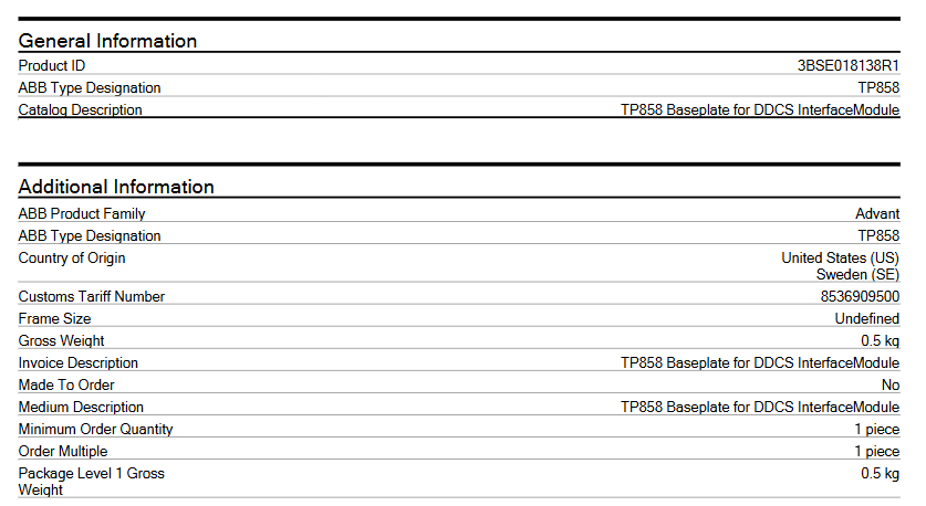
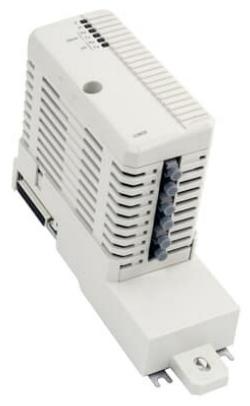
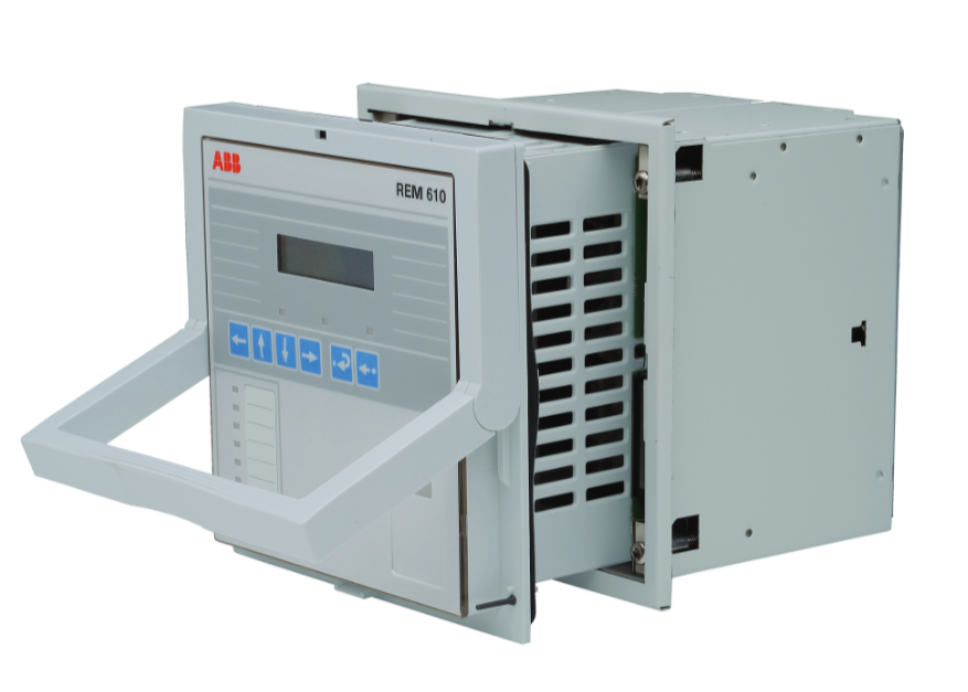
ABB 3BSE018138R1 TP858 Baseplate for DDCS InterfaceModule

Product Overview

The ABB TP858 base, as a module terminal unit specially designed for distributed digital control system (DDCS) interface modules, plays a key role in industrial automation control systems. Its design aims to provide a stable installation foundation and reliable connection support for specific interface modules, ensuring the stable operation of the entire system communication and control. This base is mainly compatible with DDCS interface modules such as CI858K01 and CI872K01, and is an important component of ABB’s construction of efficient and stable industrial control systems.

Basic information

Product identification: The product number is 3BSE018138R1, the model is TP858, the product name is “Module Termination Unit”, and the catalog description is “TP858 Baseplate for DDCS Interface Module” (used as the base for DDCS interface modules).

Product attribute: Belonging to the ABB Advant product series, it is a brand new component (Part Type: New), non customized product (Made To Order: No), and does not involve exclusive quotation (Quote Only: No).

Specification and weight

The Gross Weight and Product Net Weight are both 0.5 kg.

The frame size is’ Undefined ‘.

Customs code: 8536909500.

Environmental classification: The WEEE category is “Product Not in WEEE Scope”.

Adaptation module: The technical information mentions that it is applicable to DDCS interface modules CI858K01 and CI872K01.

Core functions

Installation support: Provide a stable and safe installation environment for the DDCS interface module, ensuring that the module’s performance is not affected by factors such as vibration and displacement during operation. Through a standard installation structure, the interface module can be easily fixed in the designated position of the control cabinet or equipment, ensuring the stable operation of the module in complex industrial environments.

Connection communication: The base is equipped with necessary connection interfaces, responsible for signal transmission and communication between the interface module and other devices. Whether it is data exchange with field devices such as sensors and actuators, or instruction transmission with the upper control system, the TP858 base can provide a reliable physical connection path to ensure stable and accurate signal transmission.

System integration: As a key foundational component of system integration, the TP858 base can organically integrate multiple interface modules into a unified control system. It builds a bridge for collaborative work between different functional modules, helps to construct a complete and efficient industrial automation control network, and improves the operational efficiency and reliability of the entire system.

Precautions

Installation environment: It should be installed in a dry, well ventilated, and non violent vibration environment, avoiding installation in places with high temperature, high humidity, or corrosive gases to prevent damage to the base and modules and affect system performance. It is recommended to control the ambient temperature between 0-50 ℃ and the relative humidity not exceeding 90% (without condensation).

Installation operation: During the installation process, it is necessary to strictly follow the operation manual. Before installation, it is necessary to ensure that all equipment is powered off to avoid safety accidents such as short circuits caused by live operation. During installation, it is necessary to ensure that the base is tightly and stably connected to the interface module, and that all interfaces are correctly connected to prevent signal transmission abnormalities caused by loose connections.

Maintenance: Regularly inspect the base and connected modules for looseness, damage, and other issues. If any problems are found, they should be dealt with promptly, such as tightening loose parts, replacing damaged bases or modules. At the same time, it is necessary to keep the surface of the equipment clean and avoid dust accumulation that may affect heat dissipation and electrical performance.

Application scenarios

In the field of industrial automation, it is widely used in automation control systems in industries such as manufacturing, energy, transportation, and construction. For example, in the automated production line of an automobile manufacturing factory, the TP858 base is equipped with relevant interface modules, which can be used to connect various sensors (such as position sensors, pressure sensors) and actuators (such as motors, cylinders), achieve precise control and data acquisition of production line equipment, and ensure efficient and stable operation of the production line.

Process control system: used in petrochemical, metallurgical, papermaking and other process industries to collect process data (such as temperature, pressure, flow rate, etc.) and control actuators (such as regulating valves, pumps, etc.). Through the collaborative work of TP858 base and interface module, real-time monitoring and precise control of the production process are achieved, ensuring the safety and stability of the production process, and improving product quality and production efficiency.

Energy industry: plays an important role in energy production and distribution systems such as electricity and water conservancy. For example, in power plants, it can be used to connect power monitoring equipment and control systems, achieve real-time monitoring and control of the operating status of power generation equipment, and ensure stable and reliable power supply; In hydraulic engineering, it can be used to control equipment such as water gates and pumps, achieving rational allocation and management of water resources.

Infrastructure field: In the construction of infrastructure such as water supply and drainage, sewage treatment, etc., the TP858 base with interface modules can be used to control related equipment, such as the start and stop of water pumps, the opening and closing of valves, etc., to achieve automated management of infrastructure operation, improve operational efficiency, and reduce maintenance costs.

ABB EXC3BSC610037R1 SD821 Power Supply Device

Basic information

Product identification: Product number EXC3BSC610037R1, model SD821, product type Power Supply Device, described as “SD821 Power Supply Device Exchange”.

Additional note: The replaced parts must be returned through RMA according to the terms and conditions, otherwise additional fees may be incurred; Refer to the cover of the power plug 5FSE707630-103.

Size and weight

The net weight of the product is 0.6 kg.

Environmental and Classification Information

Environmental related: Belongs to the “Product Not in WEEE Scope”, which means it is not within the scope of the WEEE (Waste Electrical and Electronic Equipment) directive.

Customs code: Customs tax number 8504318090.

Category

Involving multiple categories of control systems, such as 800xA under Control Systems and AC 800M related power supply in Compact Product Suite, including:

Control Systems → 800xA → I/Os → S800 I/O → S800 I/O 4.0 → Power Supplies

Power Supplies for Control Systems → 800xA → Controllers → AC 800M Hardware versions

Control Systems – Compact Product Suite – Controllers – Power Supplies for various versions of AC 800M.

Installation precautions

Environmental adaptation

The installation location should be well ventilated, away from high-temperature heat sources (such as heaters, high-power equipment), corrosive gases, dust, and sources of severe vibration. It is recommended to control the ambient temperature between -10~50 ℃ and humidity ≤ 90% (no condensation) to avoid equipment overheating or corrosion caused by environmental factors.

It needs to be installed on a sturdy flat surface or DIN rail (if supported) to ensure a secure installation and prevent looseness from causing poor contact.

Electrical Connection Specification

Confirm that the input power parameters are compatible with the device (specific parameters should refer to the official manual, industrial power supplies usually support wide voltage input). Before wiring, be sure to disconnect the upper power supply to avoid live operation.

Strictly distinguish between live wire (L), neutral wire (N), and ground wire (PE), and ensure that the grounding terminal is reliably connected to the protective grounding system to prevent electric shock or equipment damage.

The power plug should use the matching model mentioned in the document (refer to 5FSE707630-103) to avoid using non-standard plugs that may cause poor contact or safety hazards.

Space reservation

Reserve at least 10cm of space around the equipment for heat dissipation and later maintenance operations, avoiding being obstructed by other devices or cables.

Precautions for operation and maintenance

Operation Monitoring

After the first power on, observe whether the device indicator lights (such as power indicator lights and fault lights) are lit up normally, without any abnormal heating, noise or odor. If there is any abnormality, immediately turn off the power and check.

Regularly (recommended monthly) check whether the input/output voltage is stable, ensure it is within the rated range of the equipment, and avoid voltage fluctuations that may cause equipment damage or output abnormalities.

Replacement and maintenance

When replacing equipment, it is necessary to follow the document requirements: return the old parts through the RMA process, otherwise additional costs may be incurred. The replacement process must be operated by professionals to ensure that it is carried out after power failure.

When the equipment is not in use for a long time, the input power supply should be disconnected to avoid no-load losses or grid fluctuations that may affect the lifespan of the equipment.

Safety regulations

Wear insulated gloves and use insulated tools during operation to avoid direct contact with exposed wiring terminals and prevent electric shock.

When the equipment malfunctions, it is prohibited to disassemble it by oneself. ABB’s official after-sales service or professional technical personnel should be contacted for maintenance to avoid expanding the fault due to improper operation.

ABB REF615 Feeder Protection and Control

Product overview

Basic positioning: REF615 is a protection, control, measurement, and monitoring equipment designed specifically for feeders (overhead lines, cables, etc.) in public substations and industrial power systems. It supports radial, ring, and mesh distribution networks and can serve as backup protection for primary or redundant protection systems.

Core features: Designed based on the IEC 61850 standard, supporting multiple communication protocols (IEC 61850, IEC 60870-5-103, Modbus, DNP3), with compact and pluggable design, providing local HMI (human-machine interface) and web HMI, supporting hot plugging and online configuration.

Function and Configuration

Standard configuration: Provides 9 standard configurations (A-J), covering different combinations of protection functions and adapting to different grounding methods (isolated grounding, resistance grounding, compensation grounding, direct grounding, etc.). The main functions include:

Protection functions: overcurrent protection, ground fault protection (directional/non directional, based on admittance/power/harmonic principles), negative sequence overcurrent protection, phase discontinuity protection, overvoltage/undervoltage protection, frequency protection, circuit breaker failure protection, arc protection, etc.

Control functions: circuit breaker control, isolation switch control, grounding switch control, automatic reclosing, synchronization and energizing inspection, etc.

Monitoring and measurement: disturbance recorder, three-phase current/voltage measurement, sequence current/voltage measurement, power and energy measurement, circuit breaker status monitoring, trip circuit supervision, etc.

Optional functions: arc protection, automatic reclosing Modbus TCP/IP、DNP3、 Ground fault protection based on admittance/power/harmonics, power quality functions (total harmonic distortion of current/voltage, voltage fluctuations), etc.

Hardware and Interface

Physical hardware: composed of plug-in units and shells, including auxiliary power/BO modules, BI/O modules, AI/BI modules, etc., supporting multiple input/output configurations.

Interface specifications:

Analog inputs: phase current, residual current, phase voltage, residual voltage, etc.

Binary input/output: used for external signal access and control instruction output, supporting multiple terminal configurations.

Communication interface: Ethernet (100Base TX/FX), RS-232/RS-485, supporting GOOSE messages for fast communication.

Operation and Authorization

Human computer interaction: The local HMI includes a display screen, buttons, and LED indicator lights, supporting parameter settings, status monitoring, and control operations; Web HMI can be accessed through a browser and functions similarly to a local HMI.

User Authorization: Preset 4 types of user permissions (VIEWER, OPEROTOR, ENGINEER, ADMINIST), with authorization disabled by default but forced to be enabled by Web HMI, supporting password modification and audit trail (recording system and security related events).

Communications and Networking

Protocol support: IEC 61850 (including GOOSE), IEC 60870-5-103, Modbus (RTU/TCP/IP), DNP3 (serial/TCP/IP), supports horizontal communication and multi client connections.

Network topology: Supports self-healing Ethernet ring network, can connect up to 30 615 series IEDs, and requires external switches to support RSTP protocol.

Installation and wiring

Requirements for measuring transformers: The current transformer (CT) should select the appropriate accuracy level (5P, 10P) and accuracy limit coefficient according to the protection type to ensure reliable operation of overcurrent protection; Voltage transformers (VTs) must meet accuracy and insulation requirements.

Physical connection: Detailed terminal wiring methods for current, voltage, binary input/output, auxiliary power supply, etc. are specified, and wiring diagrams for different configurations may vary slightly.

Maintenance and safety

Maintenance reminder: Regularly check the wiring, indicator light status, and communication connection. When replacing components, follow safety regulations and support online replacement of some units.

Safety regulations: comply with the EMC Directive (2004/108/EC) and the Low Voltage Directive (2006/95/EC), with a protection level of IP20, and must be installed in a closed control cabinet to avoid damage to equipment caused by electrostatic discharge (ESD).

ABB DI581-S Safety digital input module

Size and weight

Dimensions: 67.5 x 76 x 62 mm.

Weight: Approximately 130 grams.

Technical Parameter

Power supply

The rated value of the process power supply voltage (UP) is 24 V DC, with an allowable fluctuation range of -15% to+20% and a maximum ripple of 5%.

Power reverse protection: equipped.

Rated protection fuse (fast): 10A.

Current consumed from UP during normal operation: 0.18 A; surge current of 0.1 A when starting a 30 V power supply (lasting for 2 seconds); Surge current of 0.06 A (lasting for 2 seconds) when starting the 24V power supply.

Installation and cooling

Installation position: Horizontal or vertical installation (the maximum working temperature drops to+40 ° C when installed vertically).

Cooling method: Natural convection, cable trays or other components inside the switchgear cabinet must not obstruct cooling.

Allowable values for power interruption (in accordance with EN 61131-2)

DC power interruption:<10 ms.

The time interval between two DC power interruptions (PS2):>1 second.

Environmental condition

Working temperature: 0 ..+60 ° C (DI581-S-XC supports a wider range in special versions).

Storage and transportation temperature: -40 degrees Celsius …+85 ° C.

Humidity without condensation: maximum 95%.

Working pressure:>800 hPa; Storage pressure:>660 hPa.

Working altitude:<2000 m; Storage altitude:<3500 m.

Mechanical properties

Protection level: IP 20.

The shell complies with UL 94 standard.

Vibration resistance (compliant with EN 61131-2, three-axis): 2 3.5 mm at 15 Hz; 1 g at 15… 150 Hz.

Impact test (three-axis): 11 ms half sine wave 15 g.

Mean Time Between Failures (MTBF): 102 years.

Technical parameters for secure digital input

Number of input channels per module: 16.

Installation and environmental precautions

Environmental adaptation

Ensure that the working environment of the module meets the parameter requirements: temperature (e.g. DI581-S conventional type is 0~+60 ° C, extreme type DI581-S-XC is -40~+70 ° C), humidity (maximum 95% non condensing), altitude (most modules<2000m), avoid corrosive gases, severe vibrations (in accordance with EN 61131-2 standard), and strong electromagnetic interference.

When installing some modules vertically (such as DI581-S), they need to be downgraded (with a maximum temperature of+40 ° C) to ensure that natural convection cooling is not hindered by cable trays or other components.

Mechanical Installation

Installed with 35mm DIN rails (7.5mm or 15mm depth), the tightening torque meets the requirements (such as DI581-S with 1.2 Nm) to avoid loosening and poor contact.

The module protection level is mostly IP20 and needs to be installed in a closed control cabinet to prevent direct contact with dust and liquids.

Precautions for Electrical Connections

Power Supply and Voltage

The power supply must comply with PELV/SELV specifications (such as DI581-S 24V DC power supply fluctuation range -15%~+20%, ripple ≤ 5%), avoid overvoltage (such as DI581-S can withstand up to 30V DC) or reverse connection (most modules have reverse connection protection, but caution is still needed).

When configuring redundant power supplies, ensure that the switching time between the two power supplies is less than 10ms (in accordance with EN 61131-2) to avoid module restarts or data loss.

Wiring specifications

Signal cables and power cables should be wired separately with a spacing of ≥ 10cm. The shielding layer should be grounded at one end to reduce electromagnetic interference (such as the RS-232/485 communication line of CI853, which needs to be shielded).

The terminal wiring of digital input/output modules (such as DI581-S) needs to distinguish between positive and negative signals (UP/ZP) to avoid short circuits (although the module has short circuit protection, it may affect other channels).

Configuration and operation precautions

Software configuration

Use official tools such as Control Builder and Automation Builder to configure and ensure firmware version is compatible with the module (e.g. AC500 CPU firmware updates need to be done through an SD card or tool to avoid firmware damage caused by power outages).

Redundancy configuration (such as module redundancy in CI853) requires enabling corresponding parameters, verifying the normal switching function before putting it into operation.

Protocol and Communication

The communication module (such as CI853 supporting MODBUS RTU, COMLI) needs to match the protocol parameters of the slave device (baud rate, parity check, etc.), and the DriveBus of CI858 needs to pay attention to the bus topology (multiple drives require NDBU branch units).

Hot plugging operations are only performed when the module is supported (such as CI853, CI858). Before plugging, ensure that there are no data transmission peaks to avoid communication interruptions.

Safety and maintenance precautions

Special requirements for security modules

The safety input module (such as DI581-S) needs to perform regular self checks (such as program flow control, RAM/CPU diagnostics) to ensure compliance with SIL certification requirements and prohibit bypassing safety function configurations.

Extreme environment modules (such as DI581-S-XC) need to be derated when the temperature is greater than 60 ° C (such as when the number of activated input channels is ≤ 50%) to avoid overheating damage.

Battery and data backup

CPU modules with batteries (such as AC500) need to be regularly checked for battery level (through function blocks or tools). When the battery level is ≤ 20%, they should be replaced in a timely manner. During replacement, the module should be powered to prevent loss of retention data.

Important data (such as the retain variable) is recommended to be backed up regularly through an SD card (using the pms_ram_deport function block for AC500 v3) to avoid data loss caused by battery failure.

Fault handling

When the module reports an error, priority should be given to checking the LED indicator lights (such as the channel LED of DI581-S and the fault LED of CI853), and troubleshooting wiring, power, or configuration issues should be carried out in conjunction with the manual. Blindly replacing the module is prohibited.

When modules involving safety circuits (such as DI581-S) fail, they need to be shut down according to safety procedures, and after troubleshooting, they can be reset using tools. Forced operation is prohibited.

Terminals for channels I0 to I7: 2.0 .. 2.7; Terminals for channels I8 to I15: 4.0 4.7.

All input reference potential terminals (negative pole of process power supply voltage, signal name ZP): 1.9… 4.9.

Electrical isolation from other parts of the module (I/O bus): available.

Input type (compliant with EN 61131-2): Type 1.

Input delay (0 ➔ 1 or 1 ➔ 0): configurable, 1 .. 500 ms。

Input signal indication: Each channel has a yellow LED, and when the input signal is high (signal 1), the LED lights up.

Signal voltage

Input signal voltage: 24 V DC.

Signal 0: -3 .. +5 V。

Undefined signal:>+5 .. < +15 V。

Signal 1:+15 .. +30 V。

Input current per channel

When the input voltage is+24 V: typical 7 mA.

When the input voltage is+5 V:>1 mA.

When the input voltage is+15 V:>4 mA.

When the input voltage is+30 V:<8 mA.

Installation and environmental precautions

Environmental adaptation

Ensure that the working environment of the module meets the parameter requirements: temperature (e.g. DI581-S conventional type is 0~+60 ° C, extreme type DI581-S-XC is -40~+70 ° C), humidity (maximum 95% non condensing), altitude (most modules<2000m), avoid corrosive gases, severe vibrations (in accordance with EN 61131-2 standard), and strong electromagnetic interference.

When installing some modules vertically (such as DI581-S), they need to be downgraded (with a maximum temperature of+40 ° C) to ensure that natural convection cooling is not hindered by cable trays or other components.

Mechanical Installation

Installed with 35mm DIN rails (7.5mm or 15mm depth), the tightening torque meets the requirements (such as DI581-S with 1.2 Nm) to avoid loosening and poor contact.

The module protection level is mostly IP20 and needs to be installed in a closed control cabinet to prevent direct contact with dust and liquids.

Precautions for Electrical Connections

Power Supply and Voltage

The power supply must comply with PELV/SELV specifications (such as DI581-S 24V DC power supply fluctuation range -15%~+20%, ripple ≤ 5%), avoid overvoltage (such as DI581-S can withstand up to 30V DC) or reverse connection (most modules have reverse connection protection, but caution is still needed).

When configuring redundant power supplies, ensure that the switching time between the two power supplies is less than 10ms (in accordance with EN 61131-2) to avoid module restarts or data loss.

Wiring specifications

Signal cables and power cables should be wired separately with a spacing of ≥ 10cm. The shielding layer should be grounded at one end to reduce electromagnetic interference (such as the RS-232/485 communication line of CI853, which needs to be shielded).

The terminal wiring of digital input/output modules (such as DI581-S) needs to distinguish between positive and negative signals (UP/ZP) to avoid short circuits (although the module has short circuit protection, it may affect other channels).

Configuration and operation precautions

Software configuration

Use official tools such as Control Builder and Automation Builder to configure and ensure firmware version is compatible with the module (e.g. AC500 CPU firmware updates need to be done through an SD card or tool to avoid firmware damage caused by power outages).

Redundancy configuration (such as module redundancy in CI853) requires enabling corresponding parameters, verifying the normal switching function before putting it into operation.

Protocol and Communication

The communication module (such as CI853 supporting MODBUS RTU, COMLI) needs to match the protocol parameters of the slave device (baud rate, parity check, etc.), and the DriveBus of CI858 needs to pay attention to the bus topology (multiple drives require NDBU branch units).

Hot plugging operations are only performed when the module is supported (such as CI853, CI858). Before plugging, ensure that there are no data transmission peaks to avoid communication interruptions.

Safety and maintenance precautions

Special requirements for security modules

The safety input module (such as DI581-S) needs to perform regular self checks (such as program flow control, RAM/CPU diagnostics) to ensure compliance with SIL certification requirements and prohibit bypassing safety function configurations.

Extreme environment modules (such as DI581-S-XC) need to be derated when the temperature is greater than 60 ° C (such as when the number of activated input channels is ≤ 50%) to avoid overheating damage.

Battery and data backup

CPU modules with batteries (such as AC500) need to be regularly checked for battery level (through function blocks or tools). When the battery level is ≤ 20%, they should be replaced in a timely manner. During replacement, the module should be powered to prevent loss of retention data.

Important data (such as the retain variable) is recommended to be backed up regularly through an SD card (using the pms_ram_deport function block for AC500 v3) to avoid data loss caused by battery failure.

Fault handling

When the module reports an error, priority should be given to checking the LED indicator lights (such as the channel LED of DI581-S and the fault LED of CI853), and troubleshooting wiring, power, or configuration issues should be carried out in conjunction with the manual. Blindly replacing the module is prohibited.

When modules involving safety circuits (such as DI581-S) fail, they need to be shut down according to safety procedures, and after troubleshooting, they can be reset using tools. Forced operation is prohibited.

ABB 3BSE000860R1 SB510 Backup Power Supply 110/230V AC

Basic information

Product identification: Product number 3BSE000860R1, model SB510, product type is Backup Power Supply.

Description: Suitable for 110-230V AC (47-60Hz) or 110-230V DC input, designed for charging 12V, 4Ah nickel cadmium (NiCd) batteries.

Exemption Statement: This component is exempt from the scope of application of the 2011/65/EU (RoHS) directive, in accordance with Article 2 (4) (c), (e), (f), and (j) of the directive (refer to 3BSE088609- EU Declaration of Conformity for ABB Advant Master Process Control Systems).

Size and weight

The net depth/length of the product is 291mm, the net height is 150mm, the net width is 60mm, and the net weight is 0.98kg.

Environmental and Classification Information

RoHS status: Compliant with EU Directive 2011/65/EU.

WEEE category: 5 categories (small equipment with no external dimensions exceeding 50cm).

SCIP: The identifier is 8a71de04-baf4-4395-9f39-8c98dd9bd6c1, and the associated country is Sweden (SE).

Customs code: HS code is 850440 (for electrical transformers, static converters (such as rectifiers), and inductors – static converters), and customs tax number is 85044082.

Related kits

The usage scenarios that are part of the suite include:

3BSE004450R1: SB510K01 Battery Charger (AC/DC 120-230V)

PM10YAC450-SB510: 10-year preventive maintenance unit

PM10YAC460-SB510: 10-year preventive maintenance unit

Category

Involving multiple categories of control systems, such as AC 400 accessories under Control System Products and power supply for Advant OCS related controllers.

Installation steps

1. Preparation before installation

Environmental inspection: Ensure that the installation location is well ventilated, away from heat sources, corrosive gases, and severe vibrations. The ambient temperature and humidity meet the requirements for equipment operation (referring to the general standards for industrial power supplies, usually -10~50 ℃, humidity ≤ 90%, no condensation).

Power matching: Confirm that the input power is 110-230V AC (47-60Hz) or 110-230V DC, consistent with the rated input of the device, to avoid damage caused by voltage mismatch.

Tools and accessories: Prepare suitable screwdrivers, wires, terminal blocks, etc. to ensure good insulation performance of the wiring tools.

2. Physical installation

Fixed method: According to the size of the equipment (width 60mm x height 150mm x depth 291mm), choose a suitable DIN rail or panel for installation, ensuring a firm installation and avoiding looseness.

Space reservation: Reserve at least 10cm of space around the device for heat dissipation and later maintenance.

3. Electrical connection

Input wiring: When connecting the input power supply, distinguish between the live wire (L), neutral wire (N), and ground wire (PE), ensure that the wiring is firm and insulated, and the grounding terminal should be reliably connected to the protective grounding system.

Battery connection: Connect 12V, 4Ah nickel cadmium (NiCd) batteries correctly according to the device identification, pay attention to positive and negative polarity, and avoid short circuits.

Wiring inspection: After the connection is completed, check whether the wiring is loose or short circuited. After confirming that there are no errors, turn on the power.

4. Power on test

When powering on for the first time, observe whether the device indicator light (such as the charging indicator light) lights up normally and confirm that the battery starts charging (if equipped with an indicator light).

Monitor whether the input voltage and output voltage are stable to ensure compliance with equipment operating parameters.

Maintenance points

1. Daily inspection (monthly)

Appearance inspection: Check whether the equipment casing is damaged or deformed, whether the wiring terminals are loose or oxidized, and whether the cables are aging.

Running status: Check if the charging is normal (such as measuring the battery voltage through the indicator light or multimeter, which should be around 13.5-14V after full charge), and there is no abnormal heating or noise.

2. Regular maintenance (every 6 months)

Cleaning and maintenance: After power off, use a dry brush or compressed air to clean the dust on the surface of the equipment and the heat dissipation holes to avoid dust accumulation that affects heat dissipation.

Battery inspection:

Measure the battery capacity. If the capacity drops below 70% of the rated value, it is necessary to replace the NiCd battery of the same model (12V, 4Ah) in a timely manner.

Check if the battery wiring is secure, and if there are any leaks, bulges, or other issues. If there are any abnormalities, replace them immediately.

Power performance test: Use a multimeter to check whether the input/output voltage is within the rated range, ensuring normal voltage regulation performance.

3. Long term storage and maintenance after discontinuation

If the device is not used for a long time, the input power should be disconnected, the battery should be removed and stored separately in a dry and cool place (temperature 0-25 ℃), and the battery should be recharged every 3 months to avoid damage caused by power loss.

Before re enabling, check the battery status and device wiring, confirm that there are no errors before powering on.

4. Fault handling

If the equipment cannot work properly, first check whether the input power supply is normal and whether the wiring is loose. After ruling out external problems, contact ABB’s official after-sales or professional technical personnel for maintenance to avoid disassembling on your own.

Precautions

Be sure to cut off the power during operation, comply with electrical safety regulations, and wear protective equipment such as insulated gloves.

Batteries are classified as hazardous materials, and waste batteries that have been replaced must be properly disposed of in accordance with local environmental regulations and cannot be discarded at will.

Maintenance records: It is recommended to establish a maintenance ledger to record the content and time of each inspection and replacement, in order to facilitate the traceability of equipment status.

ABB CI853 System 800xA hardware selector

Core functions and protocol support

Supporting protocols: Can run COMLI, MODBUS RTU, Siemens 3964R protocols, and also supports custom serial communication.

COMLI: It can be used on the built-in COM3 port and CI853 port, based on the RS-232C standard, supports asynchronous master-slave half duplex communication, supports dial-up modem control, and CI853 supports master/slave mode in this protocol.

MODBUS RTU: an open-source serial protocol based on a master-slave architecture for half duplex communication. It can be configured on the COM port of AC 800M and CI853. CI853 only supports master mode in this protocol and has no module redundancy.

Siemens 3964R: Can be used on the built-in COM3 port and CI853 port, requiring a standard RS-232C/485 communication channel.

Features: Supports hot swap and can be used in conjunction with HI controllers.

Basic information and parameters

The product code is 3BSE018103R1 (CI853K01), with 2 channels and a transmission speed of 75-19200 b/s. It supports line redundancy and module redundancy.

Up to 12 units can be connected on the CEX bus, with an RJ-45 female connector (8-pin) and a typical 24V power consumption of 100 mA.

Environment and Certification

The working temperature range is+5 to+55 ° C (+41 to+131 ° F), and the storage temperature range is -40 to+70 ° C (-40 to+158 ° F).

The protection level is IP20 (according to EN60529, IEC 529), with CE mark, ABS, BV, DNV-GL, LR classification certification, and complies with RoHS (Directive/2011/65/EU (EN 50581:2012)) and WEEE (Directive/2012/19/EU) standards.

Size and weight

Height 185 mm (7.3 in.), width 59 mm (2.3 in.), depth 127.5 mm (5.0 in.), including base weight 700 g (1.5 lbs).

Specific industrial protocol scenarios

Siemens equipment compatibility: Supports Siemens 3964R protocol and can communicate with Siemens equipment that uses this protocol. It is suitable for hybrid control systems in factories that have both ABB and Siemens equipment, ensuring collaborative work between different brands of equipment.

Custom communication requirements: It can support custom serial communication, meet the non-standard communication protocol requirements of some special industrial equipment, and provide flexibility for equipment integration in specific production processes, such as data exchange of certain customized production equipment.

High reliability demand scenario

Redundancy design application: Supports line redundancy and module redundancy, suitable for industrial scenarios that require high communication reliability, such as power systems, large chemical plants, etc. When a communication line or module fails, it can automatically switch to the redundant line or module to ensure uninterrupted communication.

Hot swappable support: Modules can be plugged and unplugged without interrupting system operation, facilitating equipment maintenance and replacement without shutting down the production line, improving system availability, and suitable for industrial scenarios of continuous production, such as automotive manufacturing production lines.

ABB CI858 Communication Interface Unit

Core functions and applications

Adopting the DriveBus protocol for communication between ABB drives and AC 800M controllers, as well as communication with ABB special I/O units.

Specially designed for segmented drive applications of ABB rolling mill drive systems and paper machine control systems, powered by processor units via CEX Bus without the need for additional external power sources.

Characteristics and Connection Specifications

Supports hot swapping.

A CI858 can connect up to 24 ABB drives, and an AC 800M controller can connect up to 2 CI858s.

If connecting multiple ABB drives, a branch unit NDBU is required to construct a logical bus with a physical star topology, and the branch units can be connected in series.

Basic information and parameters

The product number is 3BSE018135R1, the communication protocol is ABB’s DriveBus, the role is Master, the transmission speed is 8 Mbit/s, and there is no line redundancy or module redundancy function.

Up to 2 units can be connected on the CEX bus, with optical interfaces and a typical 24V power consumption of 200 mA.

Environment and Certification

The working temperature range is+5 to+55 ° C (+41 to+131 ° F), and the storage temperature range is -40 to+70 ° C (-40 to+158 ° F).

Corrosion protection complies with ISA 71.04 G3 standard, with a protection level of IP20 (according to EN60529, IEC 529).

With CE mark, it has ABS, BV, DNV-GL, LR classification certification, and complies with RoHS (DirectIVE/2011/65/EU (EN 50581:2012)) and WEEE (DirectIVE/2012/19/EU) standards.

Size and weight

Width 59 mm (2.3 in.), height 185 mm (7.3 in.), depth 127.5 mm (5.0 in.), including base weight 700 g (1.5 lbs).

Install and configure

Installation preparation: Confirm that the installation environment meets the requirements, including temperature, humidity, and other environmental conditions, and ensure that the installation location meets the requirements of protection level IP20. Prepare the necessary equipment and tools, such as DIN rails, installation screws, etc.

Installation steps: The CI858 communication interface unit adopts DIN rail installation method. During installation, it should be ensured that the module is correctly installed on the DIN rail and fixed according to relevant specifications to ensure a secure installation. Due to the fact that CI858 is powered by the processor unit through the CEX bus and does not require an additional external power supply, only attention needs to be paid to its connection to the CEX bus of the processor unit during installation. If multiple ABB drives need to be connected to CI858, a branch unit NDBU needs to be prepared and connected according to a physical star topology, and the branch units can be chained.

Configuration phase: Use the Control Builder engineering tool to configure the CI858 system. Define the system dataset by setting ABB Drive dataset parameters. Please refer to the Drive Firmware Manual for detailed information on the dataset and other required parameter settings. In the Control Builder hardware editor, parameters can be defined through the Settings tab, variables can be connected through the Connections tab, and the current value and status of each unit can be viewed through the Status tab to complete the configuration of the CI858 communication interface unit.

ABB SD833 Ability ™  System 800xA ®  hardware selector

The SD83x Power Supply Units are designed to meet all the applicable electrical safety data stated by the EN 50178 harmonized European Standard Publication and the additional safety and function data required by EN 61131-2 and UL 508.

The secondary output circuitry is accepted for SELV or PELV applications. They are switch-mode Power Supply Units that convert the mains voltage to 24 volts d.c. These power supplies can be utilized for non-redundant and redundant applications.

Redundant applications require diode voting units SS823 or SS832. With the type SD83x series Power Supply Units, there is no requirement for the installation of a mains filter. They provide a soft start feature;  power-on of an SD83x will not trip fuses or earthfault circuit breakers.

Features and benefits

Simple DIN-rail mounting

Class I Equipment, (when connected to Protective Earth, (PE))

Over-voltage Category III for connection to primary main TN network

Protective separation of secondary circuit from primary circuit Accepted for SELV and PELV applications

The output of the units is protected against over current (current limit) and over voltage (OVP)

Basic information and parameters

The product number is 3BSC610066R1, the type is power supply, the rated output current is 10A, the rated output power is 240W, the rated output voltage is 24V DC, and the rated input power is 447/514VA.

Mains/Input voltage rating is 100-120V AC, 200-240V AC, with automatic input selection. The allowed mains voltage variation is 100-120V AC ± 10%, 200-240V AC ± 10%, and mains frequency is 50-60Hz ± 6%.

At startup, the primary peak surge current is less than 10A, there is no load sharing function, no monitoring relay, the power factor at rated output power is 0.59/0.51, and the heat dissipation is 24/22W.

When the maximum current is reached, the output voltage is regulated to<70mV/<100mV, the ripple (peak to peak) is<50mV, and the secondary voltage is maintained for 46/47ms when the main power is turned off.

When the ambient temperature is less than 45 ° C, the maximum output current is 12A, and the maximum ambient temperature is 55 ° C. It is recommended to use an external fuse with a primary rating of 10-20A and a secondary short-circuit current of 14-18A. The output overvoltage protection should be less than 39V.

Environment and Certification

With CE mark, electrical safety complies with IEC 61131-2, UL 508, EN 50178 standards, not applicable to ATEX Zone 2, IECEx Zone 2, Class 1 Div 2 hazardous locations.

Having DNV-GL and ABS classification certification, protection level IP20 (compliant with IEC 60529), corrosive environment compliant with ISA-S71.04 G2 standard, pollution level 2 (compliant with IEC 60664-1), mechanical operating conditions compliant with IEC 61131-2, electromagnetic compatibility compliant with EN 61000-6-4 and EN 61000-6-2, overvoltage category III (compliant with IEC/EN 60664-1), equipment category 1 (compliant with EN 50718); 3.56), compliant with RoHS (Directive/2011/65/EU (EN 50581:2012)) and WEEE (Directive/2012/19/EU) standards.

Size and weight

Width 60mm (2.36 “), depth 117mm (4.61”), height 124mm (4.88 “), weight 700g (1.5lbs.), installation spacing width 15mm (0.59”), height 40mm (1.57 “).

ABB REM 610 motor protection relay

Product overview

REM 610 is a member of ABB’s RE_610 series digital relays, mainly used to protect large asynchronous low-voltage motors, small and medium-sized high-voltage asynchronous motors, and can cope with electrical faults during motor start-up, normal operation, idling, and shutdown cooling stages. It is suitable for equipment such as pumps, fans, mills, crushers, etc. In addition, it can also be used for the protection of cable feeders and distribution transformers that require thermal overload, overcurrent, ground fault, and phase imbalance protection.

Core functions

Protection functions: covering multiple key protection functions, including three-phase thermal overload protection (49M), motor start monitoring based on thermal stress calculation (48/14), three-phase timed overcurrent protection (51/14), three-phase instantaneous/timed short circuit protection (50/51), inverse time unbalance protection based on negative sequence current (46), phase sequence reversal protection (46R), timed undercurrent (loss of load) protection (66), instantaneous/timed earth fault protection (50N/51N), cumulative start time counting and restart suppression (37), temperature protection through RTD or thermistor (49/38), circuit breaker fault protection (62BF) and locking relay function (86), partially Functions are mutually exclusive.

Measurement function

Physical measurement of phase current and residual current, calculation of thermal overload and negative sequence current, monitoring of characteristic current during motor start-up and operation. Through the optional measurement card, up to 8 temperatures (6 RTDs and 2 thermistor sensors) can be directly measured, and the measured values can be obtained through the relay front panel or rear serial communication interface.

Recording function

Built in digital disturbance recorder with battery backup, capable of recording 4 analog signal channels and 8 digital signal channels, supporting current curve and internal and external signal recording, flexible triggering mode, and data storage in non-volatile memory. The event recorder can store 100 event codes with timestamps, which are not lost during power outages and are convenient for fault analysis.

Monitoring and self inspection

equipped with trip circuit monitoring, continuously monitoring the availability of the trip circuit and the control voltage of the circuit breaker; Built in self-monitoring system, monitors software and hardware status, alarms in case of faults, and locks protection function in case of permanent 

Faults to prevent misoperation.

Input/Output and Communication

Input/output: 4 current transformers, 2 digital inputs, 3 additional digital inputs for optional RTD module; 3 normally open overload output contacts, 2 conversion signal output contacts, and 1 dedicated IRF contact. The input and output contacts can be freely configured.

Communication: Supports multiple standard protocols such as IEC 61850, IEC 60870-5-103, Modbus, Profibus, etc. It can be directly connected through a fiber optic communication bus or connected to modules and gateways via a bus, providing multiple communication module options.

Technical Parameter

Power supply and current: There are various types of power supplies, with AC type supporting 100/110/120/220/240V AC, DC type supporting 110/125/220/250V DC and 24/48/60V DC, and voltage fluctuation allowed within a certain range; The rated current is 1A or 5A, with corresponding thermal and dynamic current tolerance capabilities.

Environment and Protection: Recommended working temperature -10…+55 ° C, storage temperature -40…+85 ° C, humidity<95% RH; shell protection level: front IP54, rear top IP40, connection terminal IP20; Through multiple electromagnetic compatibility, insulation, and mechanical tests.

Size and weight: frame width 177mm, shell width 164mm, height 177mm (4U), shell height 160mm, depth 149.3mm; weight 3.5kg, spare unit 1.8kg.

Installation and Configuration

Installation methods: Supports embedded installation, semi embedded installation, 25 ° angle semi embedded installation, rack installation, wall mounted installation, 19 “equipment frame installation, and can be equipped with test switches.

Ordering and Accessories: When ordering, specify the order number, HMI language set number, and quantity. The order number includes information such as relay type and hardware; Provide a variety of accessories, such as cables, installation accessories, test switches, optional communication cards, universal enclosures, and configuration tools.

ABB DO880 (3BSE028602R1) digital output module

Product overview

DO880 is a 16 channel 24V digital output module launched by ABB, suitable for single redundant or redundant application scenarios. The maximum continuous output current per channel is 0.5A, and the output has current limiting and over temperature protection functions. Each output channel includes a high side driver with current limiting and over temperature protection, EMC protection components, inductive load suppressors, output status indicator LEDs, and isolation barriers from the Modulabus, belonging to the S800 series mechanical structure.

Core Features and Advantages

Channel and configuration: 16 channel 24V DC current source output, adopting a set of isolation design, supporting redundant or single configuration mode.

Monitoring and diagnosis: equipped with circuit monitoring function, capable of monitoring short-circuit and open circuit loads (with customizable configuration limits); Diagnose output switch without pulse output; Equipped with advanced onboard diagnostic functions and output status indicator lights (active/error).

Safety and reliability: Starting from DO880 PR: G, it supports degraded mode for normally powered channels; Current limitation during short circuit, switch over temperature protection; The fault tolerance level of the output driver is 1 (compliant with IEC 61508), and in ND (normally off) systems, even if the output driver fails, the output can still be controlled; Passed IEC 61508 SIL3 certification and EN 954-1 Category 4 certification.

Technical Parameter

Electrical parameters

Signal specification: 24V DC (19.2-32V DC), 0.5A

Isolation: Group level and ground isolation

Rated insulation voltage: 50V

Dielectric test voltage: 500V AC

Power consumption: 5.6W (0.5A x 16 channels)

Current consumption:+5V Modulus 45mA; +24V Modular Bus maximum 50mA;+24V external 10mA

Physical parameters

Width: 45mm (1.77 “)

Depth: 102mm (4.01 “), including connector 111mm (4.37”)

Height: 119mm (4.7 “)

Weight: 0.20kg (0.44 lbs.)

Environmental parameters

Working temperature: 0 to+55 ° C (+32 to+131 ° F), certified range is+5 to+55 ° C

Storage temperature: -40 to+70 ° C (-40 to+158 ° F)

Relative humidity: 5 to 95%, no condensation

Pollution level: Level 2 (IEC 60664-1)

Protection level: IP20 (IEC 60529)

Certification and Compatibility

Certification: CE certification; Compliant with electrical safety standards such as EN 61010-1 and UL 61010-1; Hazardous area certification (C1 Div 2 cULus, C1 Zone 2 cULus, ATEX Zone 2); Classification society certification (ABS, BV, DNV, LR); Compliant with RoHS and WEEE directives.

Compatibility: Can be used in conjunction with MTUs such as TU810, TU812, TU814, TU830, TU833, TU842, TU843, TU852, etc; The key control code is FE.

Search for products

Back to Top
Product has been added to your cart