Call us 24/7uaedcs@163.com
Welcome to the official website of CNIACS Automation Technology Co., Ltd!
Call us 24/7uaedcs@163.com

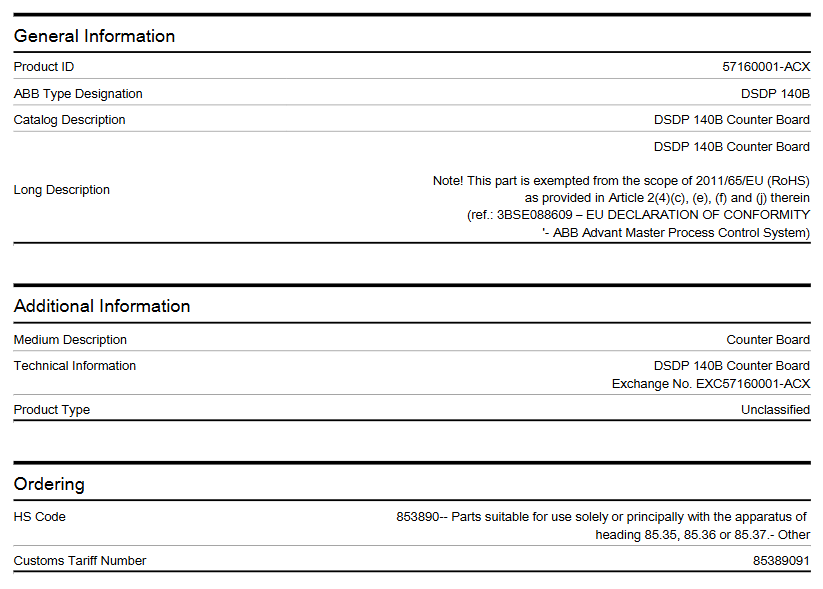
ABB AC 800PEC High Performance Control System

That is why we have designed the AC 800PEC,extending the capabilities of ABB’s well-known automation technology to handle the high-speed algorithms of processes such as power electronic applications.

Taking the technology a step further it is a dual core processor unit that combines these high speed controls with the low-speed process control tasks usually carried out by separate PLC(programmable logic controller) units. Embed into a robust and flexible system structure with integrated standard communication, the  AC 800PEC is unique in the field of industrial process controllers. The AC 800PEC is the ultimate approach for high demands.

The AC 800PEC has a unique combination of features for demanding applications:

• Short cycle times, down to 100 μs

• High processing power

• Fast communication and I/O via optical links

• Programming tools:- System engineering with IEC61131-3 languages using ABB’s Control Builder, both Compact and Professional versions available- Product and control development using MATLAB®/Simulink® for model-based design,easily bridging the gap from simulation to implementation

• Full integration into ABB Ability™ System 800xA

• Innovative and flexible use of FPGAs to include protocols and application functionality in the devices without creating additional processor load

• Optical communication

• Industrial grade hardware with no moving parts

• Long life cycle, easy upgrading

• Robust reliance file system, insusceptible post power loss

Built to control power in Process Industries

ABB has global expertise and technical know-how in processes for industrial, marine and other applications. As a result, the AC 800PEC is a key controller for ABB’s industrial applications, and also for third-party products and systems

The AC 800PEC is an efficient and flexible controller family. The benefits of short cycle times,fast (input/output) I/O, high-processing power and advanced control using MATLAB®/Simulink®:

• Increases process quality and output

• Saves development and engineering costs

• Reduces the energy consumption of you products

• Shortens time-to-market for your development project

• Saves headcount and resources in engineering and software development

• Enhances Return on Assets (ROA)

• Hardware backup trip integrated with fast

COMBI I/O

The modular structure of the AC 800PEC control system means it can adapt to any application size, from the largest industrial plants and pro pulsion systems down to very compact products,where space and cost are critical. All over the world, thousands of processors are now proving their worth in a wide variety of extremely de manding applications.

Powerful hardware for efficient, high-speed processing

The AC 800PEC combines the floating-point computing performance of the CPU with the flexibility and high-speed capability of a FPGA.

The system is separated into three performance levels covering different cycle times. Control tasks are allocated depending on their speed requirements:

• Very fast tasks down to 25 ns (nanoseconds for FPGA tasks)

• Fast tasks down to 100 μs (microseconds for Matlab/Simulink tasks)

• Slow tasks down to 1 ms (miliseconds for control tasks)

The hardware architecture of the AC 800PEC is an ideal match to the three-level software structure.

To support the short processing cycle times, the AC 800PEC provides a fast I/O system. 

Depending on the speed of the I/O connection, it is possible to achieve data throughput times below 100 μs, including the time required to read, process,write and transmit the signal.

Implementation of the AC 800PEC software on the three performance levels provides an exceptional range of control and communication functionality.

The following software packages have been developed to support each of our specific high power rectifier applications.

Aluminium applications

• AC 800PEC Unit controller ↔ AC 800PEC Master controller communication via PEC – PEC fiber optical link (100 μs)

• Units can be controlled independent from master

• Allows emergency operation (full smooth current control, in emergency mode, without AC 800PEC, available only in combination with DCS800 pre magnetization)

• Predictive maintenance features can be included

• Open circuit-, over current-, under voltage-, over voltage protection packages included in software- A newly developed OPC (open circuit protection) stand-alone PLC (programmable logic controller), working in combination with the

AC 800PEC Master controller functions or as standalone  protection, in case of the master panel maintenance

• Controlled shutdown in an event, not needing an immediate trip → less disturbance for your processes

• Potline load swing detection and load shedding function integrated in application software

• On Load Tap Changer fast tapping function in order to prevent DC current overload during disturbances

• A special potline-to-earth resistance measure ment system based on an AC 800PEC family available (PERMS)

• Maximum power regulation- To prevent over-shooting of power consumption and to support your power generators

• Maximum DC voltage regulation for stabilizing your process

Electrical arc furnace applications

• Stable arc detection

• Different control modes (constant current,constant power or constant resistance)

• Fast link to power quality system (PQS)ELREG (electrode regulation; anode hydraulic system control) features included:

• Electrode manual control (analog or digital)

• Electrode fast lift function (with or without separate fast up valve)

• Automatic arc strike function

• Automatic arc restrike function

• Adaptive electrode control according to furnace behavior or heat stage

• Superimposed integral control circuit

• Voltage fluctuation measurement (stability index calculation)

• Arc-to-roof detection/protection

• Arc-to-roof protection during arc strike sequence

• Hydraulic oil pressure supervision and  electrode protection

• Cave-in detection

• High-voltage detection

• Counter pressure valve control logic

• Voltage-to-ground supervision

• Roof voltage monitoring

• Electrode auto raise function after furnace off command (distance or position selectable)

• Blocking valve control

• Electrode speed limitation for electrode and arm protection

• Future features- Automatic proportional valve linearization check- Automatic proportional valve linearization- Dynamic voltage setpoint control for a stable melting process

Chemical applications:

• OLTC step compensation for smooth process control- IDC current step compensation for smooth current change when stepping up

• Power factor compensation by OLTC

• Predictive maintenance features can be included

• Software protection packages including:- DC over current protection- AC over- and undervoltage protection- AC phase unbalance protection- System unbalance protection for 12 pulse systems

• DC earth fault detection available by 3 voltmeter method

• Process pulse block loop with SIL 3 level

• Voltage ride-through in case of incoming voltage dips

Electrowinning industries (copper & zinc):

• IDC current step compensation for smooth current change when stepping up

• Power factor compensation by OLTC

• Predictive maintenance features can be included

• DC overcurrent protection

• AC over- and undervoltage protection

• AC phase unbalance protection

• System unbalance protection for 12 pulse systems

• Master DC current control for parallel rectifier units

• DC open loop detection during start-up

• DC open loop protection during operation

DC power supplies for graphite electrode plants

The graphitisation process demands a large variation of voltage and current from the DC power supply.

• Constant DC power suppy for the process irrespective of changing process resistance – Possible due to the very fast cycle times of  AC 800PEC controller.

• Customer tailed process recipes can be added and modified from the operator panel in order to meet the specific customer requirements.

• After adding the corresponding recipes, the rectifier follows the predefined DC current, DC voltage and maximum allowed power set points, including all necessary graphitisation specific protection functions.

ABB UNITROL ®  6080 excitation system

Product overview

UNITROL ®  6080 is an automatic voltage regulator (AVR) and static excitation system (SES) launched by ABB, suitable for small and medium-sized power applications. The system adopts mature prefabricated functional modules, supports single channel/dual channel configuration (with the option to add backup channels as needed) and multiple thyristor bridge module options, which can meet different on-site data and availability requirements and comply with international and local standards. All systems undergo 100% functional testing before leaving the factory.

Core Configuration and Design

Channel design: Up to three control/inverter channels can be constructed, including two full function channels and one backup channel for emergency generator control. Each channel can handle the maximum excitation current and has diagnostic, maintenance, and transient recorder functions.

Hardware foundation: Based on the AC 800PEC high-performance processor family, integrated into the UC D240 control, communication, and measurement board (CCM), it has high-speed processing capabilities and can achieve fast analog and digital process I/O, closed-loop control, and other functions.

Power Converter: Each channel’s power converter is selected based on the maximum excitation current and voltage requirements, providing various thyristor power converters such as D1 to D5, UNL 13300, etc. It supports single/three-phase AC power supply, has a wide rated frequency range, and can meet high availability requirements through redundant channels and online maintenance (optional).

Structural features: Adopting a compact design, saving installation space, no need for rear access, can be placed close to walls or back-to-back; The cabinet protection level standard reaches IP52, and IP54 can be provided as needed; The cooling methods include natural or forced air cooling, with the air inlet at the front and the outlet at the front or top.

Main functions and features

Control function: The standard firmware includes the necessary regulation, protection, and monitoring functions for safe operation, which can be adapted to specific needs by expanding I/O signals or adding optional software functions, including voltage regulators, excitation current regulators, various compensation and limiting circuits, etc.

Protection and Monitoring: The monitoring and protection functions can be freely configured at three different action levels, including alarm only, redundant circuit switching, instantaneous excitation tripping, etc., with multiple functions such as overcurrent protection and volt/hertz protection.

Data recording: The internal event recorder can process and store up to 2000 events, each with a timestamp; The data logger includes a pre configured section and a freely configurable section, and the recorded data can be displayed and analyzed through the excitation control terminal software.

Time synchronization: The system clock of all controllers can be synchronized with the time source through SNTP, with an accuracy of better than 1ms. The time signal can come from internal or external sources, and GPS and other signals can also be received through an optional receiver.

Communication function: Equipped with a user-friendly excitation control terminal (ECT), supporting Ethernet and multiple fieldbus protocols, capable of communicating with power plant control systems, and supporting remote service and troubleshooting.

Advantages and Value

Excellent performance: 64 bit floating-point CPU ensures no data scaling or range limitations, enabling fast and accurate measurement and control; The integrated power system stabilizer (PSS) option helps optimize grid stability.

Easy to operate: With a user-friendly interface, it is convenient for system operation, monitoring, and maintenance; Convenient debugging, parameter setting, and other functions can be achieved through the excitation control terminal (ECT).

High flexibility: It can be customized according to individual operation and environmental conditions, supporting multiple redundant configurations, including optional redundancies in control, power module, cooling, etc. The software can be programmed based on IEC 61131 standard through ABB Control Builder M, fully compatible with ABB’s Extended Automation System 800xA.

Efficiency and Guarantee: Adopting mature prefabricated functional modules to shorten delivery time; Equipped with offline tuning function, the system can be tuned and tested through a closed-loop real-time generator simulator; Provide efficient product lifecycle management to extend asset lifespan at the lowest cost, with technical support from ABB’s global excitation service network.

Application scenarios

Suitable for various scenarios, including pumped storage power plants, nuclear power plants, magnetic pole transformation of dual speed motors, online power conversion, electric braking and other engineering solutions.

Technical parameter comparison (with UNITOL 6800 SES)

Parameters: UNITOL 6080 SES/AVR/UNITROL 6800 SES

Closed loop control: supports single channel, dual channel, and backup channel (requires a third inverter module, maximum continuous DC current ≤ 800A)/supports single channel, dual channel, and backup channel

Converter module types: D1… D5, UNL 13300 (customized engineering solution as needed)/D5, UNL 13300, UNL 14300

Converter redundancy: 1+1/1+1, n-1/up to 8 modules

Maximum input AC voltage: 690V/1500V

Rated frequency: 50/60-480Hz (only AVR supports>50/60Hz, AVR also supports single-phase power supply)/50/60Hz

Maximum output continuous DC current: 1600A/10000A

Top voltage: 850V/1900V

Service and Support

Installation and commissioning: Services provided by ABB engineers with professional competence, extensive experience, and multilingual abilities.

Training: ABB University offers standard and customized training courses, as well as on-site training.

Lifecycle management: Through a lifecycle management model, we help customers extend the asset lifecycle at the lowest cost, providing various services such as technical support, remote services, maintenance and repair, and expansion upgrades.

Software tool

ECT software: can be loaded on the excitation control terminal or installed on a Windows system PC for system debugging, operation, monitoring, and maintenance. It has built-in multilingual user documentation for easy troubleshooting.

Control Builder M: Compliant with IEC 61131 standard, used for managing and customizing AC 800PEC application software, is part of ABB Extended Automation System 800xA and can run on Windows PC.

ABB electromagnetic flowmeter

Basic Product Information

Product type: Electromagnetic flowmeter, including ProcessMaster (industrial universal type) and HygienicMaster (sanitary type), used to measure the flow rate of fluids, slurries, or paste like substances with conductivity.

Measurement principle: Based on Faraday’s law of electromagnetic induction, the flow rate is calculated by the induced voltage generated by the cutting of magnetic induction lines by a conductive fluid in a magnetic field, and then the volumetric flow rate is obtained.

Equipment design:

Compact: Integrated design of sensor and transmitter.

Remote type: The sensor and transmitter are separated and connected through a signal cable (maximum line length of 50m without preamplifier, up to 200m with preamplifier).

Safety and Compliance

Safety instructions: covering safety precautions during transportation, installation, electrical connections, operation, and maintenance, including prevention of electric shock, mechanical damage, fluid leakage, etc.

Compliance: Complies with CE certification (EMC, low pressure, pressure equipment directive), EHEDG (sanitary), 3A (sanitary) and other standards, as well as RoHS and WEEE directives.

Installation and Connection

Installation requirements:

It is necessary to ensure that the flowmeter operates at full capacity, and the inlet and outlet straight pipe sections are not less than 3 × DN and 2 × DN, respectively.

The electrode axis should be horizontal or tilted no more than 45 degrees, avoiding installation at the highest point of the pipeline or at positions prone to gas accumulation.

Grounding requirements: Different grounding methods should be used according to the material of the pipeline (metal, plastic, etc.) to ensure measurement accuracy.

Electrical connections: including power supply (AC/DC multiple voltage ranges), signal cables (shielded), transmitter wiring, etc. Some models support IP68 protection level (maximum immersion depth of 5m).

Debugging and parameter settings

Debugging steps: The initial startup requires downloading system data and quickly configuring key parameters such as language, flow unit, range, pulse output, etc. through the “Easy Set up” menu.

Parameter function: Supports flow unit switching (such as m ³/h, l/min, etc.), damping setting, air traffic control detection, alarm threshold (high and low flow, air traffic control, etc.) configuration.

Operation interface: The LCD display screen supports multiple languages and can be used to navigate menus through buttons. Different operator pages can be configured to display information such as traffic and cumulative values.

Function and Technical Parameters

Core functions: bidirectional flow measurement, cumulative flow calculation, pulse/frequency output, HART communication, air traffic control detection, fault diagnosis, etc.

Technical indicators:

Measurement error: Standard calibration ± 0.4% measurement value, optional ± 0.2%.

Flow velocity range: 0.02~20m/s (depending on pipe diameter).

Working temperature: Depending on the lining material, the fluid temperature can reach up to 180 ° C (sanitary PFA lining).

Protection level: Sensor IP65/IP67/IP68, transmitter IP65/IP67.

Maintenance and troubleshooting

Maintenance points: Regularly check the grounding, sealing components, and cables, and clean them when the electrodes are contaminated; After replacing the transmitter or sensor, the system data needs to be downloaded again.

Fault diagnosis: The manual provides a detailed list of common error codes (such as coil faults, air traffic control, communication errors, etc.) and troubleshooting methods, and supports viewing real-time diagnostic data through the “Diagnostics” menu.

Applicable scenarios

ProcessMaster: Suitable for flow measurement in industrial pipelines such as chemical, water treatment, and power industries.

HygienicMaster: Compliant with hygiene standards, suitable for fields such as food, pharmaceuticals, biotechnology, etc., supporting CIP/SIP cleaning processes.

ABB SYNCHROTACT ®  5 Synchronous grid connected equipment

Basic Product Information

Product Name: SyncHROTACT ®  5 (Fifth generation synchronous grid connected equipment)

Research and Application: Produced by ABB Switzerland Ltd in Switzerland, it is used for automatic synchronization and grid connection of synchronous motors with the power grid. It supports fully automatic operation of dual channel or single channel systems and is suitable for power stations (generator grid connection) and substations (two synchronous lines grid connection) scenarios.

Core function: Ensure that the power circuit breaker closes when the voltage at both ends is synchronized, avoiding grid disturbances, circuit breaker tripping, and damage to generators and unit transformers caused by asynchronous operation.

Application scenarios

Automatic synchronization and grid connection between generators and power lines;

Automatic grid connection of synchronous and asynchronous lines and busbars;

Monitoring (synchronous inspection) of automatic or manual grid connection of power lines, generators, and non voltage lines (dead busbars).

Security and availability

Dual channel design: Two independent hardware and software channels are connected in series. The first channel is responsible for automatic synchronization, while the second channel is independently monitored and developed by different engineers using different microprocessors to avoid systematic failures and improve operational safety.

Redundancy design: Two devices are connected in parallel, and when one fails, the other can take over the function, improving system availability.

Security guarantee:

Automatic operation: Ensure safety through a compact dual channel system;

Manual operation: The synchronous inspection device is connected in series with the manual parallel gateway to ensure operational safety.

Function and Features

Core functions:

Support storage of parameters for 7 different grid connection points;

Digital input and output can be freely configured;

Compatible with rated frequencies of 50Hz, 60Hz, and 16 2/3Hz;

Can replace old versions of SYNC HROTACT systems or synchronization devices from other manufacturers.

Cost and efficiency advantages:

Strong current carrying capacity of output contacts, reducing the need for auxiliary relays, and isolating all I/O;

No need for a separate power supply;

Prefabricated units (such as SYN 5500) support multiple grid connection point selection, and the bus control system integration reduces wiring.

Debugging and integration:

Utilizing the SynView software for rapid debugging, it supports parameter recommendation, real-time data display, transient recording, and event logging (recording 256 events);

Supports protocols such as MODBUS RTU, Profibus DP, LON Bus, etc., making it easy to integrate into upper level control systems;

Equipped with Ethernet interface (TCP/IP protocol), supporting remote maintenance (accessed through IP address).

Product model and classification

SYN 5100: Simple Synchronization Check Device

SYN 5200: Synchronization Check Device with Advanced Features

SYN 5201: Automatic single channel synchronization device with frequency and voltage regulation

SYN 5202: Automatic dual channel synchronization system with serial synchronization check

SYN 5302: Redundant automatic dual channel synchronization system

SYN 5500: Auxiliary equipment (for top cap rail installation, supporting multiple grid connection points)

Technical parameters

Voltage and power:

Rated voltage range: 24/48V DC, 100-125V AC/DC, 220-250V;

Maximum power consumption (SYN 5302): 25W/35VA.

Input/output:

Measurement input (U1, U2): rated voltage 50-130V AC, allowable range 0-1.3 x rated value;

Digital input current: 6-8mA DC;

Grid connected relay: maximum switching voltage 250V AC/DC, continuous current 5A, maximum switching power 1000W/VA (on), 30W/30VA (off).

Environment and Protection:

Protection level: front IP54, back IP50;

Working temperature: -40 to+54 ° C (within the operating range specified in the technical specifications);

The anti vibration, impact and earthquake performance complies with IEC standards.

Communication and isolation:

Supports MODBUS RTU, Profibus DP and other protocols, with Ethernet remote maintenance interface;

Insulation test: 2kV (IEC 60255-5), impulse voltage test: 5kV (IEC 60255-5).

Structure and Installation

Modular casing, supporting top cap rail installation or 19 inch rack installation;

Some models support surface mounting, and the size and weight vary depending on the model (such as the SYN 5200 series weighing 8.82 lbs and the 19 inch rack model weighing 17.6 lbs).

ABB 3BSE003832R1 SC510 Submodule Carrier without CPU

Product Core Information

Product Name: SC510 Submodule Carrier without CPU

Product identification:

Product ID: 3BSE003832R1

ABB model name: SC510

Product type: Communication-Module

Media description: Consistent with the product name, clearly defining its functional positioning as a “CPU free submodule carrier”

Ordering and Customs Information

HS code: 853890, classified as “parts (other) applicable to equipment under items 85.35, 85.36, or 85.37”, belonging to the category of industrial control equipment related accessories.

Customs tariff number: 85389091, providing a basis for specific customs clearance and tax declaration.

Physical specifications

Size parameters:

Net depth/length: 288mm

Net height: 22.5mm

Net width: 486mm

Weight: Net weight 0.67kg, belonging to lightweight design, easy to install and integrate into various control systems.

Environmental and Compliance Information

RoHS compliance: Complies with the EU Directive 2011/65/EU, which restricts the use of certain hazardous substances (such as lead, mercury, etc.) in electronic and electrical equipment and meets environmental requirements.

WEEE category: classified as “5 Small equipment (with all external dimensions not exceeding 50 centimeters) “is applicable to the recycling and disposal standards for electronic and electrical equipment waste.

Battery situation: Number of Batteries is 0, no need to rely on battery power supply, reducing maintenance costs and environmental risks.

SCIP Information: Number 64ca723a-0669-4eec-a128-1d20dd256d13, registered in Sweden (SE), meets the requirements of the European Union Regulation on the Registration, Evaluation, Authorization and Restriction of Chemicals (REACH) regarding the transmission of item information.

Associated suite

3BSE011302R1: AMHWV16 HW PM510V16 SC510 and MB510, Kit

3BSE016433R1: Unclear description, Kit

3BSE016434R1: Unclear description, Kit

Product category

This product belongs to multiple control systems and communication module categories, reflecting its wide compatibility and application scenarios:

Control system products – Control and communication – AC 400- Communication module – SC510 submodule carrier – SC510 submodule carrier

Control System – Advant OCS with Master SW – Controller – Advant Controller 450- Advant Controller 450 Version 2.3- Communication Module

Control System – Advant OCS with Master SW – Controller – Advant Controller 450RMC – Advant Controller 450RMC 2. x – Communication Module

Control System Advant OCS with MOD 300 SW Controller AC460 Communication Module

Product Function and Positioning Speculation

Based on the attributes of “submodule carrier” and “communication module”, the core functions of SC510 can be inferred as follows:

As the installation and connection carrier for submodules, it provides physical interfaces and electrical connection support for other functional submodules (such as input/output modules, signal processing modules, etc.).

Participate in communication and interaction within the control system, assist in data transmission and collaborative work between different modules and controllers, and ensure the overall stability and efficiency of the system.

Due to the “CPU free” design, its functionality focuses more on hardware level carrier and communication adaptation, relying on external controllers (such as Advant Controller 450, AC460, etc.) to achieve complex logic control.

Applicable scenarios

Based on its category and associated suite, SC510 is mainly used in industrial automation control systems, especially ABB’s Advant OCS, AC 400 and other series control systems, which can be used for:

Equipment Control and Communication Integration in Manufacturing Production Lines

Construction of automated monitoring systems for industrial processes such as chemical, energy, and water treatment

Modular connection and collaborative operation of various subsystems in large industrial equipment

ABB 57160001-ACX DSDP 140B Counter Board

Product Overview

The DSDP 140B counter board, product ID 57160001- ACX, is a high-performance product carefully crafted by ABB for industrial automation control systems. Its main function is to achieve precise counting and play a key role in various complex industrial scenarios, helping to improve production efficiency and control accuracy.

Product Core Information

Product Name: DSDP 140B Counter Board

Product identification:

Product ID: 57160001-ACX

ABB model name: DSDP 140B

Physical specifications

Size:

Net depth/length: 350mm

Net height: 20mm

Net width: 255mm

Weight: Net weight is 0.44kg

Environmental and Compliance Information

RoHS status: Compliant with EU Directive 2011/65/EU requirements

WEEE category: 5 Small devices (all external dimensions do not exceed 50 centimeters)

Battery condition: No batteries included (Number of Batteries is 0)

Product category

This product belongs to multiple control systems and I/O module categories, as follows:

Control System Products – I/O Products – S100 I/O – S100 I/O – Modules – DSDP 140B Positioning Module

Control System -800xA – I/Os – S100 I/O – I/O Modules

Control System – Advance OCS (with Master software) – Controller – MasterPiece 200 and 200/1- I/O modules

Control System – Advant OCS (with Master software) – I/Os – S100 I/O – I/O Modules

Control System – Advant OCS (with MOD 300 software) – I/Os – S100 I/O – I/O Modules

Control System – Compact Product Suite – I/Os – S100 I/O – I/O Modules

​Core functions

Accurate counting: With high-speed counting technology, it is possible to accurately count the number of products and equipment operation times on the production line, providing accurate data support for production management. For example, on an automotive parts production line, the number of parts produced per hour can be accurately counted.

Speed measurement: By analyzing the frequency of the input signal, it is possible to quickly calculate the operating speed of the equipment, such as the running speed of the conveyor belt, the speed of the motor, etc., to help operators understand the operating status of the equipment in a timely manner and optimize the production process.

Position control: By combining the characteristics of input signals and counting results, precise control of equipment position can be achieved, which plays an important role in the positioning operation of automated mechanical equipment, ensuring that the equipment accurately reaches the designated position and improving production accuracy.

Precautions

During the installation process, it is essential to ensure that the power is cut off to prevent electric shock hazards and equipment damage caused by misoperation. At the same time, it is necessary to strictly follow the steps in the product installation manual to ensure correct and secure installation.

When connecting with other devices, it is necessary to carefully check whether the input and output voltage, signal type, and other parameters match, in order to avoid equipment failure or damage caused by parameter mismatch. For example, if a device with mismatched voltage is connected to the input port of the DSDP 140B counter board, it may burn out the circuit inside the board.

During use, pay attention to the temperature and humidity of the working environment. If it exceeds the specified working temperature range (-40 ° C to 70 ° C), it may affect the performance and lifespan of the equipment; Excessive humidity may cause problems such as circuit board short circuits. Therefore, try to install the equipment in a dry and well ventilated environment as much as possible.

Regularly maintain and inspect the equipment, such as checking whether the connection lines are loose and whether the equipment is operating normally. If any abnormal situation is found, the machine should be stopped in a timely manner for troubleshooting and maintenance to prevent the fault from expanding.

ABB CP405 control panel

Product overview

ABB CP405 is an industrial grade touch screen control panel designed specifically for discrete automation and various industrial HMI (Human Machine Interface) applications, suitable for industrial environments that require intuitive operation and monitoring. It adopts 7-inch TFT graphical display and resistive touch screen, which needs to be programmed and operated with CP400PB Panel Builder 400 software to achieve complex control logic and data visualization functions.

The order number of this product is 1SAP500405R0001, which complies with multiple international standards, including EMC Directive 2004/108/EC, RoHS Directive 2011/65/EC, etc. It has CE certification and can operate reliably in industrial environments.

Technical Parameter

Display and Touch

Screen specifications: 7-inch WVGA TFT LCD display screen with a resolution of 800 × 480 pixels, supporting 65536 colors, and capable of presenting various data and graphics clearly.

Touch screen: Adopting a 4-wire analog resistive touch screen, supporting over 1 million touch operations to ensure long-term reliability.

Backlight: LED backlight with a brightness of 250 cd/m ², with a backlight lifespan of up to 20000 hours at 25 ° C, and the brightness can be adjusted through the touch panel.

**Viewing angle * *: In industrial indoor environments, the vertical viewing angle is 140 ° and the horizontal viewing angle is 130 °, making it easy to view screen content from different angles.

Storage and Clock

User memory: Contains 8 MB NOR Flash and 128 MB NAND Flash, providing ample space for application and data storage.

Recipe Memory: Supports Flash storage or 128 kB battery backup RAM for convenient storage and retrieval of various recipe data.

Real time clock: Equipped with hardware clock/calendar function, powered by a 3 V 220 mAh lithium manganese dioxide (Li/MnO ₂) battery. Even when not in use and the ambient temperature is 20 ° C, the battery capacity can still maintain 95% after 5 years, ensuring accurate clock operation.

Interface and power supply

Serial port: equipped with RS-232, RS-485, RS-422 serial ports (Sub-D 9 female connector), can communicate with PLC or other controllers.

USB port: 1 USB Type A port, used to connect typical peripherals such as printers; 1 USB Type B port for programming.

Power supply: Input voltage is 24 VDC ± 10%, maximum power consumption is 10 W.

Weight: The net weight is 0.55 kg, and the total weight is 0.75 kg.

Environment and Protection

Working environment: The working temperature range is 0…+50 ° C (32… 122 ° F), and the working humidity is 10… 90% relative humidity (no condensation at 40 ° C), which can adapt to various environmental conditions in industrial sites.

Storage environment: The storage temperature range is -20…+60 ° C (-4… 140 ° F), and the storage humidity is 95% relative humidity (no condensation at 60 ° C), making it convenient for product storage and transportation.

Protection level: The front panel protection level is IP66 (requires correct installation), which can effectively prevent dust and water from entering.

Anti interference capability: Meets multiple electromagnetic compatibility standards, such as electrostatic discharge immunity testing (8 kV air discharge, 4 kV contact discharge), radiated RF electromagnetic field immunity testing, etc., to ensure stable operation in complex electromagnetic environments.

Functional Features

Software support

Run CP400PB Panel Builder 400 Runtime software, which supports offline and online simulation, facilitating program development and debugging.

It has rich HMI functions, including data acquisition, alarm processing, scheduler, recipe management, user and password management, etc., which can meet the diverse needs of industrial control.

Supports multilingual applications, making it easy to create and manage multilingual applications to meet the usage needs of different regions around the world, including Far Eastern languages.

Provide powerful scripting languages for automated HMI applications, and script debugging capabilities can improve application development efficiency.

Communication ability:

Support communication with AC500/AC500eCo PLC, Motion drivers and other devices;

Recommend using TK407 communication cable (order number 1SAP500467R0001) to connect AC500 series PLC.

Durability:

Backlight lifespan of 20000 hours (at 25 ° C);

The front panel film has a lifespan of 10 years in an environment without direct sunlight at 25 ° C.

Installation and Connection

Installation requirements:

Panel opening size: CP405 is 191.5 × 138 mm, CP408 is 259.5 × 201.5 mm;

Ensure that the installation surface is flat and the gasket is well sealed to maintain IP66 protection.

Wiring:

Power supply: Connect 24 VDC through terminal and ground (terminal 3);

Serial port pin definition: Supports RS-232 (TxD/RxD), RS-485 (±), RS-422 (TxD ±/RXD ±).

Battery maintenance: The built-in non rechargeable lithium battery is used for clock backup and must be disposed of according to local regulations.

Operation and Settings

Panel Settings: Configure display brightness, touch calibration, date and time, communication parameters, etc. through the “Panel Setup” menu.

Programming and Debugging: Connect to a PC via USB Type B interface, download the project using CP405/CP408 Panel Builder 400 software, and support automatic runtime updates.

Cleaning and maintenance: Use only a soft cloth and neutral cleaning agent to wipe, avoid touching the touch screen with solvents or tools.

ABB ACS580 standard control program

Basic information

Scope of application: Suitable for ACS580 frequency converters with firmware version ASCDX 2.05, only compatible with CCU-23 and CCU-24 control units, firmware types (ASCD2, ASCD4) distinguished by frame size (R1-R5, R6-R11)

Startup and Control

Start the process

Complete language selection, motor parameter configuration (refer to motor nameplate), direction testing, and other steps through the “First Start Assistant” on the auxiliary control panel.

Support control of start/stop, speed adjustment, and motor identification run (ID run) through I/O interface for optimizing motor control parameters.

Control mode 

Local control: Operated through the control panel or PC tools, suitable for debugging and maintenance.

External control: Remote control is achieved through I/O terminals (digital/analog inputs) or fieldbus (embedded Modbus RTU or optional adapter), supporting the switching of two external control positions, EXT1 and EXT2.

Control panel functions

Layout and buttons: including display screen, directional keys, start stop keys, local/remote switch keys, etc., supporting shortcut key operations (such as taking screenshots, adjusting brightness).

Main menu:

Basic settings: Configure control macros, motor parameters, ramp time, limit values, etc.

I/O menu: View and adjust the configuration of digital/analog input/output.

Diagnostic menu: displays faults, warnings, restriction status, and event logs.

Energy Efficiency Menu: Monitor energy consumption, energy-saving data, and CO ₂ emission reduction.

Controlling macro

Pre defined parameter configuration set, simplifying the settings for specific applications, including:

ABB standard macro: default configuration, supports 2-wire control and 3 fixed speeds.

3-wire macro: suitable for instantaneous button control.

PID macro: used for process PID control (such as pressure and flow regulation).

PFC macro: Pump and fan control, supporting linkage of multiple devices.

Other macros: such as manual/automatic switching macro, motor potentiometer macro, etc., suitable for different scenarios.

Core functions

motor control

Supports scalar control (default, suitable for simple scenarios) and vector control (requires ID operation, suitable for high-precision speed regulation).

Supports asynchronous motors, permanent magnet synchronous motors (PM), and synchronous reluctance motors (SynRM).

Speed and torque control

Speed/frequency reference values can be set through analog input, digital input, fieldbus, and other methods.

Support functions such as acceleration/deceleration ramp adjustment, constant speed control, and critical speed avoidance.

Pid control

Built in 2 sets of PID controllers for closed-loop control of process variables such as pressure and liquid level, supporting sleep/wake function for energy saving.

Protection function

It includes fixed protections such as overcurrent, overvoltage, undervoltage, and motor overheating, as well as programmable external event protection.

Support safety functions such as automatic fault reset and safe torque shutdown (STO).

Communication function

Built in Modbus RTU fieldbus interface, supporting the extension of PROFINET, EtherNet/IP and other protocols through adapters.

Parameter configuration

Parameter groups: covering actual value monitoring (01 group), input reference (03 group), faults and warnings (04 group), I/O configuration (10-15 groups), control mode (19 groups), PID settings (40-41 groups), etc., a total of 99 parameter groups.

Parameter recovery: supports resetting to default values, clearing fault logs, and backing up and restoring configurations.

Fault diagnosis

Warning and Fault: Detailed list of fault codes (such as overcurrent and overvoltage), possible causes, and solutions, supporting viewing of historical records through the control panel or event log.

Fieldbus diagnosis: Monitor communication status, send and receive data, and assist in troubleshooting bus faults.

ABB 07CR42/07CT42 Central Unit

Product overview

07CR42 and 07CT42 are expandable independent central units in the AC 31 automation system, suitable for various applications with input/output points ranging from 14 to 110. Its design makes it easy for both beginners and experienced automation users to operate, with components installed close to sensors/actuators. It supports integration with other automation systems in the enterprise through communication interfaces such as MODBUS and ASCII, expanding application possibilities.

Basic configuration rules

The AC 31 system must include a central unit, and both 07CR42 and 07CT42 integrate a certain number of binary inputs/outputs and analog inputs.

The number of inputs/outputs can be increased by adding input/output expansion units directly connected to the central unit, supporting up to 6 binary or analog expansion units.

Product model and reference information

07 CR 42-24VDC: Includes 8 isolated 24V DC inputs, 6 250V AC/2A relay outputs, 3 analog inputs (2 ± 10V voltage inputs and 1 temperature input), with RS232 interface, 24V DC power supply, 1SBP260023R1001

07 CR 42-120/230VAC: The input and output configuration is the same as the 24VDC version, with a power supply of 120/230V AC and a 24V DC output for input power supply. 1SBP260024R1001

07 CT 42-24VDC: Includes 8 isolated 24V DC inputs, 6 24V DC/0.5A transistor outputs, 3 analog inputs (2 ± 10V voltage inputs and 1 temperature input), with RS232 interface, 24V DC power supply, 1SBP260025R1001

Technical specifications

General characteristics

Characteristics: 07 CR 42 24V DC 07 CT 42 24V DC 07 CR 42 120/230V AC

I/O quantity

-Integrated binary input 8 8 8

-Integrated binary output 6 6 6

-Integrated analog input 3 3 3

-Analog potentiometer 2 2 2

-Maximum number of expansion units per central unit 6 6 6

-Maximum binary input number 104 104 104

-Maximum binary output 54 54 54

-Maximum number of analog inputs 51 51 51

-Maximum analog output 12 12 12

Interface without CS 31 interface, 1 RS232 interface (programming, MODBUS or ASCII) without CS 31 interface, 1 RS232 interface (programming, MODBUS or ASCII) without CS 31 interface, 1 RS232 interface (programming, MODBUS or ASCII)

Memory

-User program memory size (without ONLINE), 17000 words (approximately 8.5k instructions), 17000 words (approximately 8.5k instructions), 17000 words (approximately 8.5k instructions)

-User program memory size (with ONLINE), 8000 words (approximately 4k instructions), 8000 words (approximately 4k instructions), 8000 words (approximately 4k instructions)

-User program memory and constants, flash EEPROM, flash EEPROM, flash EEPROM

-Data memory SRAM、SRAM、SRAM

-Data backup, with battery, can be backed up for 20 days at 25 ° C, fully charged in 12 hours, with battery, can be backed up for 20 days at 25 ° C, fully charged in 12 hours, with battery, at 25 ° C

ABB SPAJ 110 C Earth-fault relay

Product overview

SPAJ 110 C is a non directional grounding fault relay designed for direct grounding or low resistance grounding power systems, used for selective grounding fault protection, and can be used as primary or backup protection. This relay consists of two protection stages: a low setting overcurrent stage (I ₀>) and a high setting overcurrent stage (I ₀>>). The low setting stage can choose between timed or inverse timed characteristics, while the high setting stage only supports timed characteristics and is suitable for ground fault protection of equipment such as feeders, transformers, generators, and motors.

Core functions

Protection function

Low setting neutral line overcurrent stage (I ₀>): Supports timed or inverse time characteristics (compliant with BS 142 and IEC 60255 standards, providing four types of curves: normal inverse time, extraordinary inverse time, extreme inverse time, and long-term inverse time).

High setting neutral line overcurrent stage (I ₀>>): Only supports timed characteristics and can be set to exit operation (∞).

The output relay function can be freely configured, supporting external locking signal input, and can be used in conjunction with residual voltage relays to achieve locking/unlocking operations.

Monitoring and recording

Digital display of set values, measured neutral current, memorized fault values, etc.

Record data such as maximum measured current, number of startups in each stage, and recent startup duration.

Communication and Self Inspection

The serial interface supports connecting fiber optic buses, substations, and network control systems.

Continuous self-monitoring function, automatically diagnose hardware and software faults, and trigger alarms when faults occur.

Specification parameters

Current input

Rated current (I ₙ): 1A or 5A (selected through terminals 25-27 or 25-26).

Thermal endurance: It can continuously carry 4A at 1A rated current and 20A at 5A rated current.

Dynamic current tolerance (half wave value): 250A at 1A and 1250A at 5A.

Output contact

Trip output (65-66, 68-69): rated voltage 250V AC/DC, continuously carrying 5A, can be connected and carrying 30A within 0.5s.

Signal contacts (70-71-72, etc.): rated voltage 250V AC/DC, continuously carrying 5A.

Auxiliary power supply

Module type SPTU 240 S1:80… 265V AC/DC.

Module type SPTU 48 S1:18… 80V DC.

Power consumption: about 4W statically and about 6W during operation.

Setting Range

Low setting current (I ₀>): 0.1… 0.8 × I ₙ.

High setting current (I ₀>>): 0.1… 4.0 × I ₙ or ∞ (exit).

Action time: 0.05… 100 seconds (divided into three levels).

Working principle

The relay measures the neutral line current (I ₀) through a current transformer. When the current exceeds the starting value of the low setting stage (I ₀>), the relay starts and acts after reaching the set action time; The high tuning stage (I ₀>>) is the same, but only supports timed features. The external locking signal can be input through terminals 10-11 to lock any stage or lock two stages simultaneously. When a fault occurs, the relay outputs an alarm signal, a trip signal, or activates an external automatic reclosing relay according to the configuration.

Key advantages

High flexibility: The output relay can be freely configured to adapt to different application scenarios; Support the implementation of complex protection logic in conjunction with residual voltage relays.

Strong reliability: With continuous self-monitoring function, it can detect hardware and software failures and trigger alarms, ensuring the reliability of the relay itself.

Easy to integrate: Supports serial communication interface, can be connected to fiber optic bus and control system, convenient for remote monitoring and data transmission.

Accurate measurement and recording: Digital display of key parameters, recording of fault data, facilitating fault analysis and system optimization.

Search for products

Back to Top
Product has been added to your cart