Call us 24/7uaedcs@163.com
Welcome to the official website of CNIACS Automation Technology Co., Ltd!
Call us 24/7uaedcs@163.com

ABB PFEA113 Tension Electronic Equipment

Product positioning

PFEA113 is based on Presductor ®  The high-precision tension measurement and control system of technology is used for tension detection and control in the production process of coil materials such as paper, metal strips, and plastic films. It supports multiple types of weighing sensors (PFCL 301E, PFTL 301E, etc.) and is widely used in industries such as papermaking, printing, and metallurgy.

System composition and core technology

1. System composition

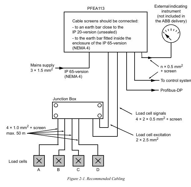
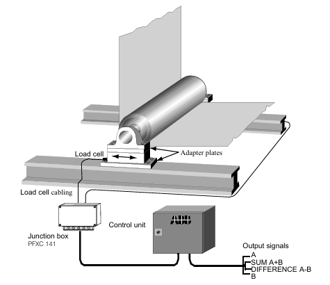
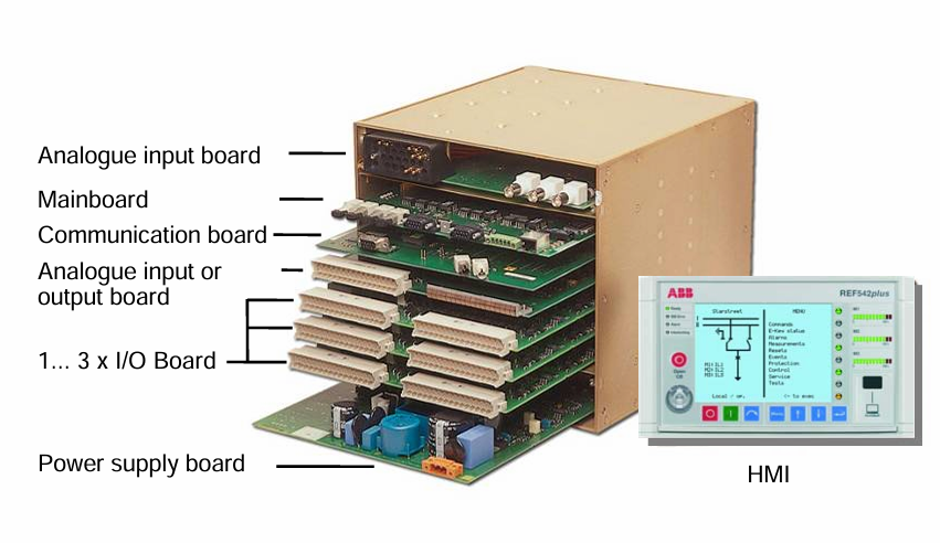
Core components: Tension electronic unit (PFEA113), weighing sensors (such as PFCL/PFTL series), junction box (PFXC 141), power module, and communication interface.

Measurement principle: Based on the magnetostriction effect, the sensor core is a stacked alloy sheet. A 330Hz AC current is passed through the primary winding to generate a magnetic field. The secondary winding induces a voltage signal proportional to the tension due to mechanical force, and has strong resistance to lateral and axial force interference (error ≤± 0.5%).

2. Core Features

Multi scenario adaptation: Supports single roll, double roll, and segmented roll applications, and can connect up to 12 sensors (cascaded through 3 PFEA113).

Flexible expansion: 6 configurable analog outputs, 4 digital outputs, supports Profibus DP communication, compatible with remote control and data upload.

High reliability: It has protection functions such as overvoltage (OVP), overcurrent (OCP), and over temperature (OTP), and supports fault self diagnosis.

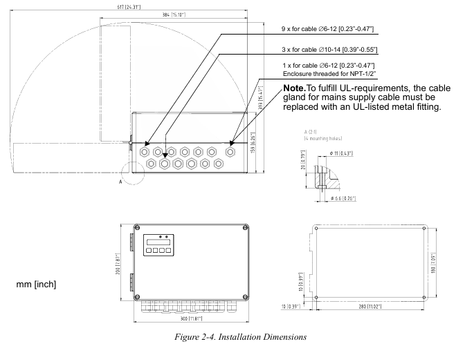
Installation and wiring specifications

1. Installation environment requirements

Physical environment: Operating temperature -10~+55 ℃ (IP20 version), -25~+70 ℃ (IP65 version), relative humidity ≤ 95% (no condensation), avoid strong electromagnetic interference sources (such as frequency converters).

Mechanical requirements: The flatness error of the installation surface should be ≤ 0.1mm, and the gap between the sensor and the adapter plate should be clean and free of debris to avoid force diversion affecting measurement accuracy.

2. Hardware wiring

Sensor wiring:

Analog input supports CT (1A/5A), VT (100V), and sensor signals, and the cable needs to be twisted shielded with a single end grounding of the shielding layer.

Switching input/output adopts optocoupler isolation, with digital output capacity 5A@250V  AC/DC, Inductive loads require parallel freewheeling diodes.

Power and Communication:

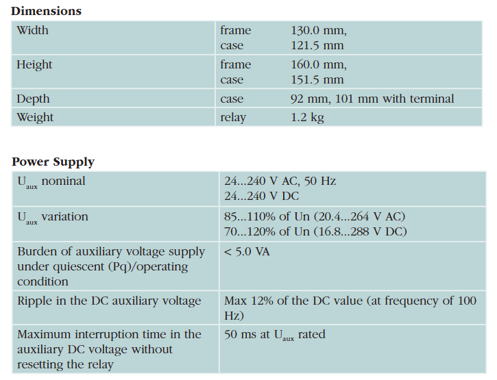
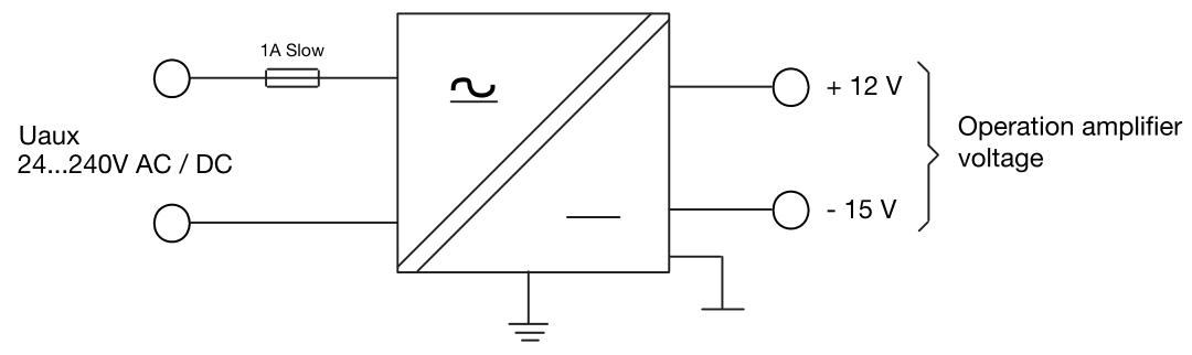
Wide range auxiliary power supply (24-250V AC/DC, IP20 version) or 85-264V AC (IP65 version), power consumption<15W.

The communication interface supports Profibus DP (RS485) and RS232, with a standard 120 Ω terminal resistor and a maximum communication distance of 1200m.

Debugging and configuration process

1. Basic settings

Quick configuration: Set language (English/German/French, etc.), unit (N/kN/kg, etc.), and web width (applicable to N/m, etc.) through panel buttons, supporting fast zero calibration and gain scheduling.

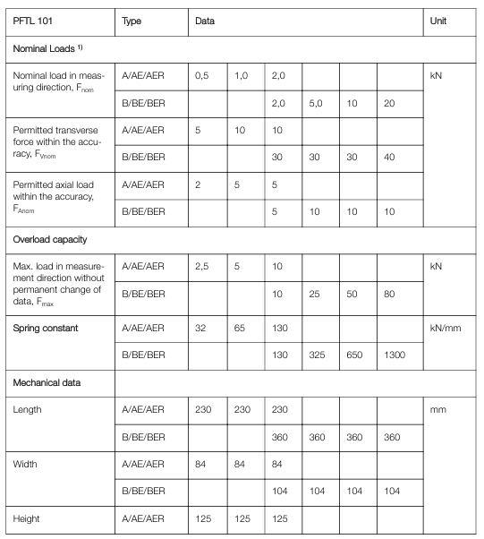
Complete configuration: including system definition (single roll/double roll/segmented roll), sensor type selection, nominal load setting, zero calibration, and wrrap gain calculation (calculated by hanging weight or formula).

2. Key parameter configuration

Wrap gain: the ratio of tension (T) to sensor measured force (FR), calculated as Wrap gain=T/FR, which needs to be derived through geometric relationships based on the installation angle (horizontal/inclined).

Communication settings: Profibus DP address (0-125), baud rate (up to 12Mbps), supports real-time data exchange with PLC or SCADA systems.

Operation and maintenance

Daily operating procedures

1. Startup and shutdown

(1) Startup steps

Pre inspection

Confirm that the main power supply voltage matches the rated value of the equipment (IP20 version: 24V DC; IP65 version: 85-264V AC).

Check that the sensors, junction boxes, and communication cables are securely connected without looseness or damage.

Power on operation

Turn on the external power switch, and the IP65 version requires the internal switch of the device to be turned on at the same time.

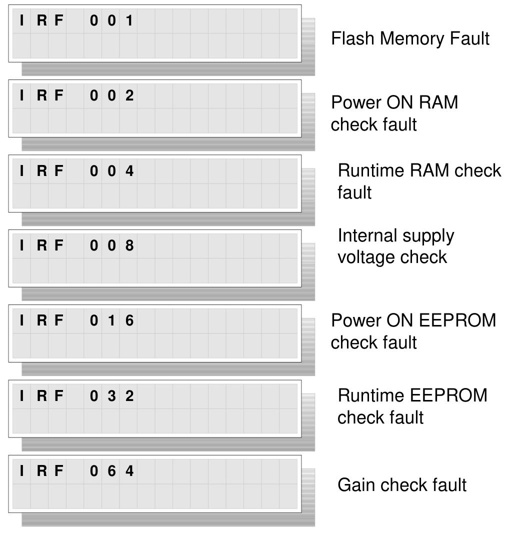
The “Power” indicator light (green) on the observation panel is on, and the “Status” indicator light (green) is constantly on, indicating that the system is normal; If the “Status” light is red, the fault information needs to be viewed through the display screen.

(2) Shutdown steps

Turn off the external power switch. For IP65 version, the internal switch of the device needs to be turned off first.

When the machine is shut down for a long time, it is recommended to disconnect the main power supply and protect the equipment from dust.

2. Operation monitoring

(1) Panel operation

Display switching: Use the “Step up/down” button to switch display content, including single sensor tension (such as Tension A), total tension (such as TensionRoll 1), differential tension (such as TensionDiff A-B), and analog output values (AO1-AO6).

Parameter viewing: Press and hold the “OK” button for 5 seconds to enter the menu, where you can browse the system status, fault records, and configuration parameters (such as w_rap gain _, nominal load).

(2) Remote monitoring

Through Profibus DP communication, the upper computer (such as PLC) can read tension values, sensor status, and alarm information in real time, and support remote sending of zero calibration, gain switching, and other instructions.

3. Key operational functions

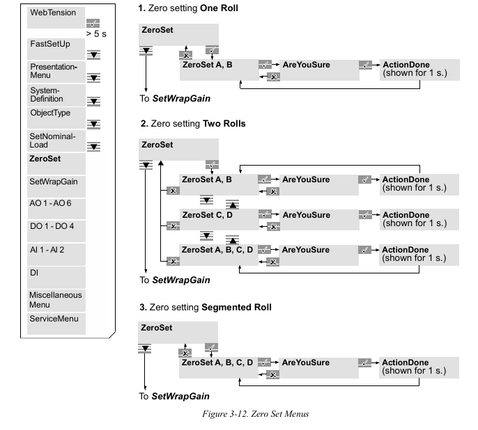
(1) Zero point calibration

Trigger condition: When no tension is applied (such as when the coil is not running), execute it through the “Zero Set” menu on the panel or remote command.

Operation steps:

Enter the “ZeroSet” menu and select the corresponding sensor group (such as A, B).

After confirming that there is no tension, press “OK” and the display screen will show “ActionDone” to indicate completion.

(2) Gain scheduling

Application scenario: Suitable for changes in coil path (such as different wrrap angles), switching preset wrrap gain parameters through digital input or Profibus.

Setting method: Enable “GainScheduling” in the “SystemDefinition” menu, and configure the w_rap gain 1_ and w_rap gain 2h respectively.

2、 Maintenance and upkeep

1. Preventive maintenance

(1) Regular check (recommended every 6 months)

Key operating points for inspection items

Check the torque of the fixing screws for sensors and connectors (e.g. 24Nm for M12 screws), and clean the dust or debris in the gap between the sensor and adapter board.

Confirm that the cable and shielding layer are not worn, and that the shielding layer is grounded at one end (distance ≤ 50mm) to avoid interference caused by grounding at both ends.

Ventilation openings for heat dissipation and environmental cleaning equipment ensure that the working environment temperature and humidity are within the rated range (without condensation or corrosive gases).

(2) Calibration and verification

Calibration cycle: It is recommended to perform accuracy calibration once a year, using standard weight or calibration equipment to verify measurement errors (should be ≤ ± 0.5% FS).

Verification method: Enter a known tension value through the simulation function in “DataMenu”, and compare the displayed value with the theoretical value.

ABB Presductor PFTL 101 series pillow block weighing sensor

Product positioning

PFTL 101 series sensors are based on Presductor ®  High precision force measurement equipment for technology is mainly used for tension detection of coils (such as paper and metal strips) in medium and low voltage industrial environments. By measuring the reaction force generated by the tension of the coil, precise control of the production process is achieved.

Product Overview and Core Features

1. Model and classification

The PFTL 101 series includes 6 models, divided into two categories based on range and material:

A-series: Range 0.5-2 kN (PFTL 102A/AE/EAR), suitable for low tension scenarios;

B series: Range 2-20 kN (PFTL 101B/BE/BER), suitable for medium tension scenarios.

Among them, the “AE/BER” model is made of acid resistant stainless steel (1.4404 material), suitable for corrosive environments; The “AER/BER” model is additionally equipped with fixed cables to enhance sealing.

2. Measurement principle

Based on the magnetostriction effect: The sensor core is a laminated alloy sheet, and a magnetic field is generated by passing 330Hz AC power through the primary winding. The secondary winding induces a voltage signal proportional to the tension due to mechanical force. It is only sensitive to forces in the measurement direction and has strong anti-interference ability against lateral and axial forces (with an allowable error of ≤± 0.5%).

3. Key technical parameters

Parameter A series (0.5-2 kN) B series (2-20 kN)

Accuracy level ± 0.5% FS ± 0.5% FS

Linear deviation<± 0.3% FS<± 0.3% FS

Lag error<0.2% FS<0.2% FS

Working temperature range -10~+105 ℃ -10~+105 ℃

Compensation temperature range+20~+80 ℃+20~+80 ℃

Overload capacity (without permanent deformation) 5 times rated load 4-5 times rated load

Material: Stainless Steel (1.4104)/Acid Resistant Steel (1.4404) Stainless Steel (1.4104)/Acid Resistant Steel (1.4404)

System composition and installation specifications

1. System composition

The complete measurement system includes:

2 weighing sensors (used in pairs);

Junction box (signal summary);

Control unit (such as PFXC 141, outputting signals A, B, A+B, A-B);

Adapt cables and installation accessories (adapter board, screws, etc.).

2. Installation requirements

Mechanical installation:

Installation surface flatness error ≤ 0.05mm, adapter plate thickness A series ≥ 30mm, B series ≥ 35mm;

The sensor is fixed with 6 screws (recommended 12.9 grade alloy screws, torque 136-649 Nm, depending on size) to avoid deformation caused by over tightening;

Horizontal or inclined installation is allowed, and when inclined, the measurement force needs to be corrected using the angle compensation formula (see manual 2.5.3).

Electrical connection:

The cable needs to be fixed to avoid generating additional force, and the shielding layer should be grounded at one end;

The primary winding provides a power supply of 0.5A/330Hz, and the secondary signal output impedance is 1-3 Ω, with strong anti-interference ability.

Debugging and maintenance

Debugging steps

Check the installation flatness, screw torque, and cable connection;

Perform zero calibration through the control unit (recalibration is required after replacing the sensor);

Calculate the measurement force under maximum tension (1/2 of the total force borne by each sensor) and set the control unit range.

ABB Procontic T200 Control System Hardware

Product positioning 

Procontic T200 is a compact industrial automation control system designed for small and medium-sized industrial processes such as machinery manufacturing, light industry, water treatment, etc. It achieves logic control, data acquisition, and process monitoring through modular hardware design, while also considering flexibility and reliability.

Hardware composition and core modules

System architecture

Modular design: composed of central processing unit (CPU), input/output (I/O) modules, power module, communication module, and rack, supporting distributed expansion (connected to remote I/O stations through bus), with a maximum expansion of 2048 I/O.

Redundancy option: Supports CPU, power, and communication bus redundancy in critical scenarios to enhance the system’s ability to withstand failures.

Core hardware modules

(1) Processor module (CPU)

Model examples: T200-CPU110, T200-CPU120, based on 16 bit/32-bit microprocessors, with computational capabilities supporting complex logic control (such as ladder diagram and functional block diagram programming).

Key parameters:

Program storage capacity: 128KB~512KB (non-volatile memory), supports online program modification.

Data storage: 64KB RAM (with battery backup, power-off data storage ≥ 72 hours).

Integrated communication interface: standard RS485 (supporting Modbus RTU), some models include Ethernet port (supporting TCP/IP).

(2) Input/Output (I/O) Module

Digital input module:

Models such as T200-DI16 (16 point DC input), supporting 24V DC signals, response time ≤ 1ms, optocoupler isolation (2500V AC), compatible with proximity switches, limit switches, and other sensors.

Digital output module:

Model such as T200-DO16 (16 point relay output), contact capacity 5A@250V  AC/DC, Support inductive loads (requiring external current diodes); Or transistor output (24V DC, 0.5A/point), response time ≤ 0.1ms.

Analog module:

Input module (T200-AI8): 8-channel, supports 4-20mA/0-10V signals, resolution of 12 bits, sampling period of 100ms, compatible with temperature transmitters, pressure sensors, etc.

Output module (T200-AO4): 4-channel, 4-20mA output, accuracy ± 0.1% FS, used to drive actuators such as regulating valves and frequency converters.

(3) Power module

Model: T200-PS24 (24V DC output), T200-PS110/220 (110V/220V AC input, 24V DC output), optional output current of 5A/10A, overload protection (150% load limited current), short circuit protection (self recovery).

When configuring redundant power supplies, it is necessary to achieve interference free switching through dedicated redundant modules.

(4) Communication and Expansion Module

Bus module: T200-BUS module supports PROFIBUS DP or MODBUS Plus bus, realizing communication between master station and remote I/O slave station, with a maximum transmission rate of 12Mbps and a distance of ≤ 1000m (without relay).

Ethernet module: The T200-ETH module provides a 10/100Mbps Ethernet port, supports TCP/IP and FTP, and is used to connect to HMI or SCADA systems on the upper computer.

Hardware installation and connection

1. Rack and module installation

Rack specifications: Standard 3U rack (19 inches), supporting 16 module slots, with plug-in design for modules. The front panel screws need to be locked to prevent loosening during installation.

Installation environment: Operating temperature of 0-55 ℃, relative humidity of 5% -95% (no condensation), vibration level ≤ 5g (10~500Hz), and should be kept away from strong electromagnetic interference sources (such as frequency converters and high-power motors).

2. Electrical connection specifications

Power connection: The input side is connected to the protective grounding (PE), and the output side 24V DC “+” “-” should correspond to the I/O module. It is recommended to use a 1.5mm ² shielded wire with a single ended grounding of the shielding layer.

I/O wiring: Digital signals use 0.5mm ² wires, while analog signals require twisted pair shielded wires (with a distance of ≥ 30cm from the power line). The wiring terminal numbers correspond one-to-one with the module channels (such as AI1 corresponding to terminal 1/2).

Communication wiring: The PROFIBUS bus uses a dedicated bus cable (impedance 150 Ω) with terminal resistors (150 Ω) at both ends. The connector uses a D-type 9-pin plug to ensure good pin contact.

System Expansion and Compatibility

Local expansion: Connect up to 3 expansion racks through rack expansion interfaces, with a total I/O point count of no more than 2048 and an expansion distance of ≤ 1m (between racks).

Remote expansion: Connect remote I/O stations (such as T200-RIO) through the PROFIBUS DP bus, supporting up to 31 slave stations and a distance of up to 10km (with relays).

Compatibility: Supports communication with other ABB Procontic products (such as T300) and third-party devices (such as Siemens S7 series, Schneider Modicon series), and is compatible with OPC servers for data integration.

​Application scenarios

Procontic T200, as a small and medium-sized distributed control system, is suitable for:

Logic control and production line linkage of packaging machinery and printing equipment;

Pump valve control and liquid level/flow regulation for water treatment and sewage treatment;

Temperature and pressure closed-loop control of reaction vessels in small and medium-sized chemical plants;

The conveyor belt speed control and material sorting system for warehousing and logistics.

ABB REF542plus multifunctional protection

Core functions and characteristics of the device

Protection function

Core protection: covering overcurrent, ground fault, circuit breaker failure and other protections, supporting timed and inverse time characteristics, and can be configured with multiple sets of fixed value groups to adapt to different operating conditions.

Featured features:

Three stage overcurrent protection (including quick break, time limited quick break, and overload).

Non directional grounding fault protection, supporting high-sensitivity zero sequence current detection.

Statistics of circuit breaker operation frequency and life monitoring, assisting in preventive maintenance.

Control and operation

Control mode: Supports 4 control modes (local, remote, no control, local+remote), switched by electronic key to prevent misoperation.

One device operation: The “select execute” mechanism on the HMI panel can be used to control the opening and closing of the circuit breaker, in conjunction with interlocking logic to ensure operational safety.

Measurement and monitoring

Measurement quantity: Real time monitoring of three-phase current, voltage, power, frequency, electrical energy, etc., with accuracy in accordance with IEC standards and a refresh cycle of about 0.5 seconds.

Events and Wave Recording:

Record 30 latest protection events (including time, fault type, measurement value) without loss during power outage.

Support fault recording, storing 4 analog signals (current/voltage waveforms) and 8 digital signals (switch status) for easy fault analysis.

Human Machine Interface (HMI)

Hardware composition

Display area: 320 × 240 resolution LCD, with a single line diagram (SLD) of the device displayed on the left and menus and data displayed on the right. It supports switching between multiple languages such as Chinese and English.

Operating components: 8 navigation buttons (menu, up and down, enter, etc.), 3 sets of LED indicator lights (M1-M3, displaying load rate), 8 programmable three color LEDs (indicating protection actions, alarms, etc.).

Security component: Electronic key sensor, distinguishing between “protection key” (modifying protection parameters) and “control key” (switching control modes), supporting hierarchical management of permissions.

Menu Structure

Main menu: Contains submenus such as commands, alarms, measurements, events, protection, control, services, and testing, supporting operations such as parameter viewing and modification, event queries, and device self checks.

Featured feature page:

Debugging mode: requires a super user key to enter, which can directly drive switch output and monitor analog input for wiring verification.

Time synchronization: Supports local settings or remote synchronization of time through GPS and SCADA systems.

Communication and Configuration

Communication capability

Supporting protocols: Modbus RTU, IEC 60870-5-103, SPA, LON, etc., standard RS485 interface, optional fiber optic communication module.

Data interaction: It can remotely upload/download configurations, read measurement values, record events and faults, and connect to a PC through infrared (IrDa) or RS232 interfaces.

Configuration management

Tool support: Configuration needs to be done through ABB’s dedicated operating tool (such as REF542comf), which supports offline configuration download and online configuration upload.

Parameter storage: Configuration and fixed values are stored in non-volatile memory, which is not lost when powered off. It supports two modes: temporary modification and permanent saving.

Installation preparation and environmental requirements

Environmental conditions

Temperature: Operating environment temperature -25 ℃~+55 ℃, storage temperature -40 ℃~+85 ℃, avoid drastic temperature changes.

Humidity: Relative humidity ≤ 93% (no condensation), avoid humid, dusty or corrosive gas environments.

Vibration and Shock: Compliant with IEC 60255-21 standard, vibration frequency 10-150Hz, acceleration ≤ 1g; shock acceleration ≤ 10g (11ms pulse).

Altitude: ≤ 2000m, if exceeded, it needs to be downgraded for use.

Installation space and safety

Space requirements: The device is approximately 177mm in width, 177mm in height, and 149mm in depth. At least 150mm of operating space should be reserved in front and behind for easy wiring and maintenance.

Safety regulations:

Only qualified personnel are allowed to install, strictly following local electrical safety regulations.

The device frame must be reliably grounded (grounding resistance ≤ 10 Ω) to avoid electrostatic damage to electronic components.

Cut off the auxiliary power supply before wiring to prevent electric shock.

Hardware installation and wiring

Mechanical installation

Installation method: Supports panel embedded installation, 19 inch rack installation, or direct installation of circuit breaker cabinets, fixed with matching brackets to ensure stability and no looseness.

Installation steps:

According to the installation hole position fixing device, check the levelness (deviation ≤ 1 °).

Connect the grounding terminal to ensure reliable grounding.

Install the HMI panel, fasten it firmly, and avoid dust from entering through large gaps.

Wiring specifications

(1) Power wiring

The auxiliary power interface (X10) supports 24~250V AC/DC and needs to distinguish between positive and negative polarities. It is recommended to use 1.5mm ² single core copper wire.

The power circuit needs to be equipped with a 2A fuse to avoid overcurrent damage to the device.

(2) Analog input (X80~X88)

Current input: Supports CT (1A/5A) or Rogowski coils, three-phase current requires continuous wiring (such as L1 connected to X81, L2 connected to X82, etc.), and neutral wire connected to the common terminal.

Voltage input: Supports VT (100V) or resistive voltage divider, and the wiring of line voltage and phase voltage needs to be configured with corresponding devices (set through operating tools).

Wiring requirements: Analog cables need to be shielded, with the shielding layer grounded at one end and a distance of ≥ 100mm from the power cable to avoid electromagnetic interference.

(3) Switching input/output (X20~X41)

Switching input: 14 channels/module, supporting 24-250V DC, using optocoupler isolation, input current 2-20mA, distinguishing between “common terminal” and “signal terminal” during wiring.

Switching output: 8 channels/module, including relay output (capacity) 5A@250V  AC/DC), Used to drive circuit breaker coils or alarm signals, the output contacts need to be connected in parallel with freewheeling diodes (when inductive loads are present).

(4) Communication wiring

RS485 interface (X60~X61): using shielded twisted pair, A and B wires are connected correspondingly, and the terminal needs to be connected to a 120 Ω matching resistor, with a maximum communication distance of 1200m.

Fiber optic interface (X62~X65): Glass fiber optic or plastic fiber optic, with a bending radius of ≥ 100mm, to avoid signal attenuation caused by excessive bending.

ABB REF601 digital feeder protection device

Core functions of the device

Protection function

Overcurrent protection:

Three stage overcurrent protection (I>, I>>, I>>>), supporting timed and inverse time characteristics (compliant with CEI 60255 standard), covering short-circuit faults.

The inverse time limit feature can be selected as “normal inverse time limit” or “extreme inverse time limit”, adapting to the action logic under different fault current levels.

Ground fault protection:

Two stage non directional grounding fault protection (I ₀>, I ₀>>), detects grounding faults through zero sequence current, and the action value can be set to 1% -800% of the rated current, supporting timed delay (0.02-60s).

Cable thermal overload protection:

Based on the current based thermal accumulation model, the cable temperature (θ>) is monitored to prevent insulation aging caused by long-term overload. The alarm/trip threshold can be set to 50% -100% of the rated temperature, with a time constant of 1-200 minutes.

Other auxiliary protections:

Phase sequence interruption protection (Δ I>): detects three-phase current imbalance, with an action value of 10% -100% (based on maximum/minimum phase current difference), and a delay of 1-300s.

Circuit Breaker Failure Protection (CBFP): Monitor circuit breaker faults, with an action time of 0.1-60 seconds, in conjunction with external fault detection logic.

Measurement and monitoring functions

Measurement quantity: Real time monitoring of three-phase current, residual current, phase imbalance, thermal overload level, 1-minute current demand and maximum value, with accuracy in accordance with IEC 61557-12 standard.

Event record: Store 100 events with time stamps (protection start, trip, self-test fault, etc.), without loss during power outage, and support reading through local interface.

Fault waveform recording: Record 4 analog signals (current waveform) and 8 digital signals (protection signal, circuit breaker status), non-volatile storage for easy analysis after faults.

Self monitoring function: Real time monitoring of power supply, hardware modules, and communication status, triggering alarms in case of faults to ensure device reliability.

Control and Communication

Control function: Supports local/remote opening and closing control of circuit breakers, adopts a “select execute” mechanism to prevent misoperation, and has built-in trip circuit monitoring (TCS) to monitor the integrity of the control circuit.

Communication interface: Standard RS485 interface, supports Modbus RTU protocol, can be connected to power distribution automation system (SCADA), realize remote parameter tuning, data uploading and status monitoring.

Hardware and Technical Parameters

Hardware structure

Compact design: Small in size (approximately 100mm x 160mm x 120mm in width x height x depth), suitable for embedded installation in small switchgear (such as ABB UniGear series).

Input/output:

Current input: Supports 1A or 5A rated CT, 3 phase currents+1 zero sequence current, low input impedance (<20m Ω at 5A).

Digital input: 2 main inputs (supporting 24-250V DC), expandable to 5 channels, response time<3ms.

Relay output: 2 trip outputs (SO1, SO2), 1 alarm output (SO3), rated current 5A (continuous), 30A (short-term 0.5s).

Key technical parameters

Power supply: Supports 24/48/110/220V DC or 110/230V AC, power consumption<8W (static),<12W (running), voltage fluctuation range ± 20%.

Environmental adaptability: working temperature -25 ℃~+55 ℃, storage temperature -40 ℃~+85 ℃, anti vibration (10-150Hz), anti electromagnetic interference (in accordance with IEC 61000-4 series standards).

Accuracy level: Current measurement level 0.5, protection setting error<± 5%, time error<± 5% or ± 50ms (whichever is greater).

Application scenarios

Typical applications: feeder protection for medium and low voltage distribution networks (cables/overhead lines), backup protection for small transformers, and protection for industrial distribution circuits.

Adaptation system: Italian local distribution system that meets CEI standards, especially suitable for small switchgear with strict space requirements, can replace traditional electromagnetic relays, improve protection accuracy and automation level.

Operation and maintenance

Local operation: Basic operations are achieved through panel buttons and LED indicator lights (run, alarm, trip), supporting local parameter tuning (password permission required).

Debugging tool: It is necessary to connect the device through specialized software (such as ABB PCM600 simplified version) for parameter configuration, fault record reading, and firmware upgrade.

Installation requirements: Reliable grounding (grounding resistance<10 Ω) is required to avoid close installation with strong interference sources (such as contactors and frequency converters), ensuring measurement accuracy and anti-interference ability.

Summarize

REF601 focuses on the basic protection needs of medium and low voltage distribution systems with “compact, reliable, and practical” as its core. By integrating protection, measurement, and communication functions, it simplifies switchgear design and adapts to the CEI standards of the Italian market. It is an economical choice for small distribution circuit automation.

ABB RELION ® 610 series REF610 feeder protection relay

Product overview

REF610 is ABB Relief ®  The feeder protection relay in the 610 series is designed specifically for feeder protection, measurement, and monitoring in power and industrial distribution systems, and is suitable for the following scenarios:

Protection of incoming and outgoing lines in distribution stations.

Backup protection for motors, transformers, and generators.

Special environments such as ships and offshore platforms.

Its core features include:

Modular design: Adopting a plug-in structure, it facilitates the debugging of switchgear and quick replacement of relays.

Multi protocol support: Compatible with communication protocols such as IEC 61850, IEC 60870-5-103, DNP3, Modbus, Profibus, etc., to meet the integration requirements of different automation systems.

Function integration: integrating protection, measurement, and monitoring, supporting extended functions such as arc protection and automatic reclosing.

Core functions

Protection function

Specific functional categories and key parameters

Three stage overcurrent protection (low setting value I>, high setting value I>>, instantaneous I>>>) starting value: 0.30-35.0 × In, time characteristics support definite time and inverse time (IEC 60255-3, IEEE C37.112)

Grounding fault protection two-stage non directional grounding fault (low setting value I ₀>, high setting value I ₀>>) Start value: 1.0% -800% In, supports timed and inverse time characteristics

Cable thermal overload protection based on current (θ>) Rated current: 0.30-1.50 × In, alarm/trip threshold: 50% -100%, time constant 1-200min

Phase sequence interruption protection detects phase current imbalance (Δ I>). Start value: 10% -100% (based on maximum/minimum phase current difference), with a delay of 1-300s

Circuit breaker failure protection monitoring circuit breaker fault (CBFP) action time: 0.10-60.0s, voltage threshold triggers external fault detection

Arc protection (optional) supports 2 fiber optic sensors to detect arc faults in switchgear, busbars, or cable terminals with an action time of less than 15ms (optical signal), in conjunction with current criteria to improve reliability

Automatic reclosing can be performed up to 3 times, supporting three-phase operation with a reclosing frequency of 0-3 times and a dead time of 0.1-300 seconds. After successful reclosing, the protection will resume with a delay in starting

The locking relay function records the tripping status of the circuit breaker to prevent misoperation and linkage with the tripping circuit, and supports remote reset

Monitoring and measurement functions

Measurement quantities: three-phase current, residual current, phase imbalance, thermal overload level, 1-minute demand, and maximum value.

Fault recording: 4-channel analog signal (current waveform)+8-channel digital signal (protection start/trip signal, etc.), non-volatile storage, supporting post fault analysis.

Event recording: Store 100 events with time stamps, without loss during power outages, for easy traceability of status before and after faults.

Circuit breaker monitoring: Built in counter records the number of operations, evaluates the wear status of the circuit breaker, and supports preventive maintenance plans.

Trip circuit monitoring: Real time monitoring of the on/off status and control voltage of the trip circuit, covering the opening/closing status of the circuit breaker.

Technical Parameter

Basic dimensions and weight

Describe numerical values

Width (frame) 177 mm

Width (shell) 164 mm

Height (frame, 4U) 177 mm

Height (shell) 160 mm

Depth (shell) 149.3 mm

Protective relay weight 3.5 kg

Backup unit weight 1.8 kg

Power parameters

Model Rated voltage range Voltage fluctuation range Static power consumption Operating power consumption

REF610CxxHxxx AC 100/110/120/220/240V; DC 110/125/220/250V AC 85%~110%; DC 80%~120% <9W <13W

REF610CxxLxxx DC 24/48/60V DC 80%~120% <9W <13W

Other DC ripple up to 12% (100Hz); Auxiliary voltage interruption<50ms without resetting; Start to trip response time<350ms —

Current input parameters

Description: 0.2A rated value, 1A rated value, 5A rated value

Rated frequency 50/60Hz ± 5Hz 50/60Hz ± 5Hz 50/60Hz ± 5Hz

Continuous heat tolerance of 0.5A; 1s 20A; 10s 5A continuous 4A; 1s 100A; 10s 25A continuous 20A; 1s 500A; 10s 100A

Dynamic current withstand (half wave value) 50A 250A 1250A

Input impedance<750 m Ω<100 m Ω<20 m Ω

Measurement range: 0-50 × In (phase current); 0~20 × In (grounding current) as above

Digital input parameters

Describe main inputs (DI1, DI2) and extended inputs (DI3~DI5, optional)

Rated voltage REF610CxHxxxx: 110/125/220/250V DC with the same main input or supporting 24/48/60V DC (REF610CxLxxx)

When the action threshold is 110V DC, the maximum voltage is 88V (-20%); Maximum 19.2V (-20%) at 24V DC as above

The working range is rated voltage ± 20% as above

Current consumption 2-18 mA as above

Power consumption<0.9 W/input as above

Output parameters

Signal output (SO1, SO4~SO5)

Describe numerical values

Rated voltage 250V AC/DC

Continuous current carrying 5A

3-second short-term current carrying 15A

0.5s short-term current carrying 30A

Breaking capacity (L/R<40ms) 1A at 48V DC; 0.25 at 110V DC

Core application areas

REF610 as Relief ®  The 610 series feeder protection relay is mainly used in the following scenarios:

Distribution station incoming and outgoing line protection: covering the incoming and outgoing circuits of public and industrial distribution systems, providing core protection such as overcurrent and grounding faults.

Equipment backup protection: As a backup protection for motors, transformers, and generators, it supplements the main protection function and improves system reliability.

Special Environmental Adaptation: Suitable for harsh environments such as ships and offshore platforms, meeting industrial grade requirements for anti vibration and temperature resistance.

Arc protection extension: Combined with optional fiber optic sensors, it enables rapid detection and isolation of arc faults in switchgear, busbars, and cable terminals.

ABB RE.216 series digital protection and control device operation

Hardware description

System composition

Modular structure: Composed of electronic equipment racks (such as 216MB66) and input/output units (I/O), the number of modules can be expanded according to demand (such as redundant power supplies and processor units).

Two versions:

Cabinet version: includes a 216MB66 rack, input transformer unit (216GW61), output relay unit (216GA61), etc., suitable for complex protection scenarios.

Compact version: Higher integration, such as 216MB68 rack, suitable for small switchgear, supports single system or redundant system configurations.

Core modules

Module Type Model Example Function Description

The auxiliary power supply unit 216NG61/62/63 converts the station battery voltage to 24V DC, supports redundant configuration, and is compatible with 48/60V, 110/125V, and 220/250V DC inputs.

The processor unit 216VC624 runs protection logic, stores configuration parameters, supports communication protocols such as SPA BUS and LON BUS, and has a computing power of 425%.

The analog input unit 216EA61 receives CT/VT signals and digitizes them, providing 24 analog input channels.

The binary input/trip unit 216DB61 processes 16 binary inputs and 8 trip outputs, supporting trip logic matrix control.

Injecting unit REX010 provides injection signals for stator/rotor ground fault protection, used in conjunction with REX011 transformer block.

Redundant Design

Support dual auxiliary power supply and dual processor unit configuration to ensure that a single fault does not affect system operation.

Parallel bus B448C enables communication between modules, and redundant power supply lines USA/USB ensure power continuity.

Protection function settings

Function Overview

Protection Library: Contains over 30 protection functions that can be flexibly activated and support multiple configurations (such as multi-stage overcurrent protection).

Computing power: A single processor unit supports up to 48 activation functions, and the complexity and repetition rate of these functions affect the computational load (such as differential protection accounting for 40% and overcurrent protection accounting for 2-5%).

Core Protection Functions

Differential protection

Generator Differential (Diff Gen): Suitable for two winding generators, based on nonlinear current characteristics, high stability against ride through faults, minimum operating current of 0.1IN, slope of 0.25.

Transformer Differential (Diff Transformer): Supports two winding/three winding transformers, including excitation inrush current suppression (second harmonic braking), compensating for differences in transformer ratio and wiring group.

Overcurrent protection

Current DT: Can be set as overcurrent or undercurrent, supports single-phase/three-phase measurement, with a delay of 0.02-60 seconds.

Current Inv: Compliant with BS142 standard, providing normal inverse time, extreme inverse time and other characteristics, suitable for different fault current levels.

Voltage and frequency protection

Stator EFP: 100% stator winding grounding fault is detected by injecting signals, and 95% voltage type protection covers the entire range.

Overexcitation protection: monitors the V/f ratio to prevent overheating of the iron core and supports inverse time characteristics.

special protection

Pole Slip protection: detects generator and system out of step, determines slip direction through impedance trajectory, and can set alarm and trip angle thresholds.

Distance protection: Multi segment impedance protection, suitable for power lines, supports power swing locking, weak feedback logic, and is compatible with multiple grounding systems.

Operation and maintenance

Human Machine Interface (HMI)

Configure parameters through PC or portable terminal, support function activation, fixed value modification, and event record viewing.

The local indicator light (LED) displays the operating status (such as “AL” alarm, “RUN” running).

Self monitoring and testing

Built in self-test function, monitoring power supply, module communication, and I/O channel faults, triggering corresponding alarms.

Support offline testing mode, inject simulated signals to verify protection logic, without affecting the actual circuit.

Installation and Wiring

The cabinet version requires the installation of racks and I/O units according to the drawing layout to ensure reliable grounding.

The compact version can be embedded in a 19 inch rack to save space, and the wiring needs to meet insulation requirements.

Application scenarios

Generator protection: covering differential, stator/rotor grounding, overcurrent, overexcitation, etc., suitable for different capacity units.

Transformer protection: Differential protection combined with backup overcurrent, suitable for two winding/three winding transformers.

Line protection: distance protection is the main protection, combined with directional overcurrent to achieve rapid selective tripping.

Industrial scenario: Suitable for overload and stall protection of motors such as pumps and fans, supporting integration of multiple communication protocols into automation systems.

Summarize

The RE.216 series devices are centered around modular design and flexible configuration, covering the protection needs of power generation, transmission, and industrial fields. Its rich protection functions, redundant design, and standardized communication enable seamless integration into modern power systems, ensuring safe equipment operation and simplifying maintenance processes. The manual provides a detailed explanation of the hardware architecture, functional parameter settings, and application cases, providing comprehensive guidance for engineering design and on-site debugging.

ABB REM615 Motor Protection and Control

Product Overview

REM615 is ABB Relion ®  The dedicated motor protection and control relay in the 615 series is designed specifically for the protection, control, measurement, and monitoring of asynchronous motors in the industrial field. Its characteristics include:

Compact design: adopting a withdrawable unit structure, suitable for compact space installation.

Communication standardization: fully supports IEC 61850 standard (including Edition 2), compatible with process bus IEC 61850-9-2 LE, and also supports IEC 60870-5-103, Modbus ®、 DNP3 and other protocols can support Profibus DPV1 through the protocol converter SPA-ZC 302.

Flexible configuration: Provides four standard configurations (A, B, C, D), which can be customized through the graphical signal matrix and application configuration function of PCM600 tool to meet specific user needs.

Standard configuration

The core differences and applicable scenarios of the four standard configurations are as follows:

Applicable scenarios for configuring core functions

A basic motor protection (including RTD temperature measurement option), including overcurrent, thermal overload, negative sequence overcurrent and other motors that only require basic protection, such as small pumps and fans

B adds voltage and frequency protection and measurement on the basis of A, supporting RTD temperature measurement for motors that require voltage/frequency monitoring, such as medium-sized compressors

C includes voltage and frequency protection and measurement, without RTD option for industrial motors with low temperature monitoring requirements

D supports voltage and frequency protection, using sensor inputs (instead of traditional CT/VT) to adapt to compact switchgear (such as ABB UniGear Digital) motors

All configurations include basic functions such as fault recording, event logging, self-monitoring, and can be expanded with options such as high-speed output module (HSO) and arc protection according to requirements.

Core functions

Protection function

Overcurrent protection: including three-stage non directional overcurrent (low/high/instantaneous), zero sequence overcurrent, covering motor short circuits and ground faults.

Motor specific protection: thermal overload protection (MPTTR), locked rotor protection (JAMPTOC), start-up monitoring (STTPMSU), phase sequence protection (PREVPTOC), etc., suitable for the entire life cycle of motor start-up and operation.

Voltage and frequency protection: under voltage (PHPTV), negative sequence overvoltage (NSPTOV), frequency anomaly (FRPFRQ), etc., to cope with voltage/frequency fluctuations in the power grid.

Enhanced protection: Optional arc protection (ARCSARC) can be used to quickly detect arc faults through light sensors, reducing equipment damage; Circuit breaker failure protection (CCBRBRF) ensures reliable fault removal.

Control function 

Support local/remote control of circuit breakers, isolating switches, and grounding switches, using a “select execute” mechanism to ensure operational safety.

Integrated Emergency Start Function (ESMGAPC) allows for forced start of hot state motors to adapt to emergency conditions.

Measurement and Monitoring

Real time measurement of electrical quantities such as current, voltage, power, frequency, etc., with an accuracy of ± 0.5% (current/voltage).

Status monitoring: Circuit breaker status (SSCBR), trip circuit monitoring (TCSSCBR), current circuit monitoring (CCSPVC), etc., supporting preventive maintenance.

Wave recording and logging: The disturbance recorder can record 12 analog signals and 64 switch signals. The event log stores 1024 events (with timestamps) and supports post fault analysis.

Communication and synchronization

Network redundancy: Supports redundant protocols such as HSR, PRP, RSTP, etc. to ensure communication reliability.

Time synchronization: Supports IEEE 1588 v2 (accuracy 4 µ s), SNTP, IRIG-B, and meets the time synchronization requirements of process buses.

Technical parameters

Power supply: Supports AC 100-240V or DC 24-250V, power consumption ≤ 21W.

Input/output:

Analog input: CT rated 1A/5A, VT rated 60-210V AC; Configuration D supports sensor input (75mV-9V).

Binary input: 24-250V DC, response time<3ms; output contact capacity up to 30A (short-term).

Environmental adaptability: Working temperature -25~+55 ℃, protection level IP54 (front)/IP20 (back), anti electromagnetic interference in accordance with IEC 61000-4 series standards.

Installation and Configuration

Installation method: Supports embedded, semi embedded, and 19 inch rack installation, compatible with various switchgear.

Configuration tool: Parameter setting, logic configuration, and graphical display editing can be performed through PCM600 software, and remote access to Web HMI is supported (must be enabled).

Human machine interface: Provides two sizes of LCD displays, with the large display supporting custom single line diagrams (SLDs) to visually display device status.

Application scenarios

Mainly used for asynchronous motor protection in the industrial field, including:

Rotating equipment such as pumps, fans, compressors, etc;

Heavy industrial motors such as crushers and mixers;

Suitable for medium voltage motors in compact switchgear.

Flexible configuration can meet the motor protection requirements of different voltage levels (medium and low voltage) and different operating conditions (continuous operation/intermittent start).

ABB RELION ®  650 series RET650 transformer protection device

Device application and core functions

General application scenarios

Suitable for two winding/three winding transformers, autotransformers, generator transformer groups, and parallel reactors, providing fast selective protection, monitoring, and control, supporting a wide frequency range (adapted to system disturbances and unit start stop).

Core features:

Differential protection with built-in transformer ratio matching and vector group compensation, without the need for intermediate CT;

2nd/5th harmonic braking suppresses excitation inrush current and overexcitation;

Supports IEC 61850-9-2LE process bus and can connect to 4 merging units (MU);

Pre configuration package (A01: single circuit breaker two winding transformer; A05: Single circuit breaker three winding transformer.

Main protection functions

Differential protection:

T2WPDIF (two windings)/T3WPDIF (three windings): Based on the theory of symmetrical components, it can detect internal inter turn faults with high sensitivity, support stable fault crossing and surge current braking.

REFPDIF (low impedance limited ground fault): Quickly detect winding ground faults, including directional zero sequence current criteria.

Backup protection:

Current protection: instantaneous phase overcurrent (PHPIOC), four step directional phase overcurrent (OC4PTOC), etc;

Voltage protection: Two step undervoltage (UV2PTUV), overvoltage (OV2PTOV), residual overvoltage (ROV2PTOV);

Frequency protection: Underfrequency (SAPTUF), Overfrequency (SAPTOF), Frequency Change Rate (SAPFRC).

Configuration and Analog Input

device configuration

The basic configuration includes one binary input module and one output module, supporting custom logic (such as automatic opening/closing logic) through PCM600 tool.

A01 configuration: Two winding transformer, including differential protection, overcurrent protection, voltage monitoring, etc., suitable for 12 analog inputs (7I+5U).

A05 configuration: Three winding transformer with extended winding related protection functions, supporting multiple circuit breaker scenarios.

Analog input settings

Current channel: CT transformation ratio (CTprim/CTzc) and star point direction (CTStarPoint: ToObject/FromObject) need to be set, examples include star/triangle CT connection methods and parameter calculations.

Voltage channel: Set the VT ratio (VTprim/VTsec), support star/open delta VT connections, and provide different wiring schemes for high/low impedance grounding systems.

Key parameters: The reference current (IBase) should match the CT rated current, and the minimum operating value should not be less than 4% of the rated value of the IED input (40mA for 1A input and 200mA for 5A input).

Local HMI and Operations

Hardware composition

320 × 240 pixel LCD display screen, 15 programmable tri color LEDs (red/yellow/green), navigation keyboard (including function keys, directional keys, confirm/cancel keys).

LED indication: Ready (running status), Start (protection start), Trip (trip), supports multi page display and priority control.

functional operation

Menu navigation: Access settings, events, measurements, and other functions through the Main menu, supporting parameter modification (numerical/string/enumeration types).

Communication port: Front end RJ-45 port (default IP: 10.1.150.3), only used for temporary debugging, not connected to LAN.

Detailed explanation of core protection functions

Differential protection (T2WPDIF/T3WPDIF)

Principle: Compare the current flowing into/out of the transformer, compensate for the ratio and phase difference, and distinguish internal/external faults through braking characteristics (proportional braking, second harmonic braking).

Key settings:

Minimum operating current (IdMin): default 0.3 times rated current;

Braking characteristics: Three slope sections (Section 1/2/3), suitable for different fault current ranges;

Zero sequence current compensation (ZSCurrSubtrWx): eliminates the influence of zero sequence current caused by external grounding faults.

Low impedance limited ground fault (REFPDIF)

Applied to windings directly grounded or grounded through a zig zag transformer, detecting the difference between neutral wire and phase current, the action value (IdMin) is usually set to 30% of the rated current of the winding.

Overexcitation protection (OEXPVPH)

Based on V/Hz ratio monitoring of iron core overexcitation, it supports custom inverse time characteristics and is suitable for scenarios such as generator step-up transformers. The action time is related to the overexcitation multiple (such as an action time of about 100 seconds at 1.2 times).

Control and Communication

device control

Support the control of circuit breakers (SXCBR) and isolating switches (SCSWI), including a “select execute” mechanism to ensure operational safety.

Automatic voltage control (TR1ATCC/TR8ATCC): regulates voltage through on load tap changers, supports single/parallel transformer control, including line voltage drop compensation and circulating current suppression.

communication protocol

Supports IEC 61850-8-1 (GOOSE for horizontal communication), DNP3.0, IEC 60870-5-103, etc., and is compatible with station level automation systems.

Network security: Supports role-based access control (RBAC), certificate management, and complies with power system security standards.

Monitoring and Logic

monitor function

Measurement quantities: current (CMMXU), voltage (VMMXU), power (CVMMXN), sequence components (CMSQI/VMS QI), with an accuracy of 0.5 level.

Event recording: Fault waveform recording (DRPRDRE), operation event (EVENT), supporting post fault analysis.

Logic function block

Trip Logic (SMPPTRC): Supports three-phase/single-phase tripping, including locking function;

General logic: AND, OR, TIMERSET, etc., customizable protection logic chain.

Summary

RET650 as RELION ®  The core product of the 650 series integrates differential, backup, control, and communication functions required for transformer protection, and adapts to complex power grid scenarios through flexible configuration and high-precision measurement. The manual provides detailed guidance on setting up from basic configuration to advanced functions, providing comprehensive support for engineering design, debugging, and operation and maintenance. It is suitable for transformer protection needs in the power generation, transmission, and industrial fields.

ABB RET670 Transformer Protection Device

Product positioning and application

RET670 is ABB Relion ®  The transformer protection device in the 670 series is mainly used for fast, selective protection, monitoring, and control of double winding, three winding transformers, autotransformers, generator transformer groups, and parallel reactors. Its design can adapt to a wide frequency range, cope with power grid disturbances and frequency changes during generator start stop, and is suitable for various circuit breaker configurations (single circuit breaker, multiple circuit breakers). It also provides six pre configuration schemes to meet different scenario requirements, such as transformer backup protection, voltage control, and the application of dual winding/triple winding transformers in single circuit breaker or multiple circuit breaker arrangements.

Core protection function

Differential protection

It includes dual winding (T2WPDIF) and triple winding (T3WPDIF) transformer differential protection, with automatic CT ratio matching and vector group compensation functions. It avoids excitation inrush current misoperation through second harmonic and wave blocking braking, and prevents overexcitation misoperation through fifth harmonic braking. It has high sensitivity to winding turn faults.

Low impedance limited ground fault protection (REFPDIF): As a supplementary protection for winding ground faults, it includes a zero sequence current direction criterion, with high sensitivity (as low as 5%) and rapid action.

High impedance differential protection (HZPDIF): can be used to limit ground faults or differential protection of autotransformers, tertiary reactors, etc., requiring external CT current summation, series resistance, and varistor coordination.

Impedance protection

Quadrilateral characteristic distance protection (ZMQPDIS, etc.): used for backup protection of transformer and connected power grid faults, supports multiple fault loops, can independently set directional or non directional modes, and has load intrusion detection function.

Mu Ou characteristic full range distance protection (ZMHPDIS, etc.): four zone protection, suitable for backup protection of lines and cables, supporting single pole automatic reclosing.

Current protection

Instantaneous/four step overcurrent protection: covering phase current, residual current, negative sequence current, etc., supporting direction and voltage control, providing multiple inverse time characteristic curves.

Thermal Overload Protection (TRPTTR): Based on a dual time constant thermal model, it estimates the internal temperature of the equipment and provides two-level warning and trip functions.

Circuit Breaker Failure Protection (CCRBRF): Quickly trip surrounding circuit breakers when the circuit breaker refuses to move, supporting current, contact, or adaptive criteria.

Other Protection

Voltage protection: including overvoltage (OV2PTOV), undervoltage (UV2PTUV), residual overvoltage (ROV2PTOV), etc., can be set with inverse time limit or definite time limit characteristics.

Frequency protection: including under frequency (SAPTUF), over frequency (SAPTOF), and frequency change rate (SAPFRC) protection, used for load shedding, power generation control, etc.

Overexcitation protection (OEXPVPH): prevents transformer/generator from overheating and damage due to high magnetic density, supports custom inverse time curve.

Control and monitoring functions

control function 

Synchronization Check and Synchronization (SESRSYN): Check the voltage synchronization on both sides of the circuit breaker, support manual and automatic reclosing, and adapt to dual busbar, ring busbar and other arrangements.

Equipment Control (APC): Used for controlling and monitoring circuit breakers, isolating switches, etc., supporting the “select execute” principle and providing command models for different safety levels.

Tap control (TR1ATCC, etc.): Automatically adjust the transformer tap to stabilize the secondary voltage, supporting control of single or multiple parallel transformers.

Monitoring and Recording

Measurement function: Real time monitoring of parameters such as voltage, current, power, frequency, etc., calculating positive sequence, negative sequence, and zero sequence components.

Event and disturbance recording: Built in disturbance recorder (DRPRDRE), records analog and switch data before and after faults, supports Comtrade format for easy fault analysis.

Counter and Measurement: The Pulse Counter (PCGGIO) records external pulses, while the Energy Calculation Function (ETPMMTR) calculates active/reactive energy and maximum demand.

Communication and Interface

Communication functions and protocols

RET670 has rich communication capabilities, supports multiple industry standard protocols, and can flexibly access automation systems at different levels, including:

Station level communication protocol

IEC 61850-8-1: Implemented through a single or dual channel fiber optic Ethernet interface (OEM module), supports GOOSE peer-to-peer communication, facilitates data exchange between intelligent electronic devices (IEDs) from different manufacturers, can upload perturbation files, and has a communication rate of 100BASE-FX.

LON protocol: Connected through an optical LON interface, supporting the expansion of existing ABB station level LON networks, achieving peer-to-peer communication and collaborative work with other ABB IEDs, with a communication rate of 1.25 Mbit/s.

SPA/IEC 60870-5-103 protocol: Implemented through serial and LON communication modules (SLM), SPA protocol is suitable for simple substation automation systems, IEC 60870-5-103 supports multi vendor device integration, and communication rates can be configured (such as 9600, 19200 Bd, etc.).

DNP3.0 protocol: implemented through electrical RS485 or fiber optic Ethernet interface, supporting TCP/IP and EIA-485 communication, with event transmission, time synchronization, and disturbance reporting functions, suitable for communication with RTU, gateway, or HMI systems.

Redundant communication: Supports IEC 62439-3 parallel redundancy protocol (Edition 1 and Edition 2), achieves redundant station level communication through dual ports, and improves communication reliability.

Remote communication: It can exchange analog and switch signals with remote IEDs through Line Data Communication Module (LDCM), supports IEEE/ANSI C37.94 standard, suitable for short distance (<60 km) and medium distance (extended to<3 km through optical to electrical converters) communication, supports multiple fiber types (multimode, single-mode) and wavelengths (850 nm, 1310 nm).

Search for products

Back to Top
Product has been added to your cart