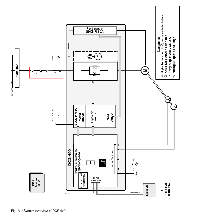
Positioning and Application: A new generation compact DC drive device with a rated current of 20-1000A and a power of 9-522kW, suitable for 230-500V AC power supply and widely used in industrial machinery drive scenarios.
Core advantages: Combining the ease of use of analog transmission with the advantages of digital transmission, compact size, easy installation, integrated exciter (including fuses and reactors), using IGBT excitation technology without the need for voltage adaptation transformers, supporting guided debugging and application macro configuration, improving efficiency and reducing errors.
Technical Parameter
Power and Environment:
Three phase power supply 230-500V, allowable ± 10% deviation, frequency 50/60Hz; electronic power supply 115-230V, allowable -15%/+10% deviation.
Working temperature: rated current+5~+40 ℃, power module+40~+55 ℃; Storage temperature -40~+55 ℃, transportation temperature -40~+70 ℃; Relative humidity of 5-95% without condensation.
Structure and size:
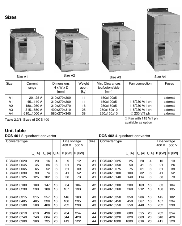
Divided into four sizes A1-A4, weighing 11-38kg, with a protection level of IP00 (power module), ventilation space needs to be reserved for installation (such as 150mm and 100mm above and below A1).
Overload capacity: Depending on the load cycle (DC I-DC IV), it supports 150% -200% overload, with a duration ranging from 10 to 120 seconds.
Cooling and power consumption: Some models require fan cooling (such as A1’s 45-140A with 2 × CN2B2 fans), and power loss varies with load (such as A1’s 20A model losing 49W at 100% load).
FUNCTION
Application macros: preset 8 macro configurations, define digital I/O, reference source and other functions. For example, Macro 1 (standard mode) supports analog speed reference and external torque limitation, while Macro 8 (torque control) uses analog quantity as torque reference.
Control function:
Speed control: supports speed generator, encoder, back electromotive force feedback, with functions such as S-shaped slope, 2 sets of acceleration and deceleration slopes, and automatic demagnetization.
Current/torque control: including current limit, torque limit, I ² t motor protection, supporting switching of second current limit.
Self optimization: It can automatically optimize parameters such as armature current, excitation current, speed controller, etc.
Communication and Interface: Supports RS232, Panel Port, and various fieldbuses (PROFIBUS, MODBUS, etc.) to transmit control commands, reference values, and status information through datasets.
Installation and Connection
Installation steps: Drill holes (92 × 92mm) according to DIN 43700 standard, and fasten the equipment with clamping claw screws to ensure ventilation space.
Wiring requirements:
The power and signal terminals are connected by plug-in screws, with a maximum wire cross-section of 1.5mm ² (2.5mm ² for relays) and a maximum relay output of 250V AC/1A.
Grounding and shielding: The protective grounding needs to be connected, and the shielding layer of the signal cable is fixed on the shielding terminal board.
Operation and Debugging
Control panel: parameter settings, fault diagnosis, local operations are implemented through the DCS400 PAN panel, supporting multilingual display and guided debugging.
Debugging process: Use the “Commissioning” function to configure motor parameters (rated current, voltage, speed, etc.) step by step, select control mode, and perform self optimization to ensure system matching.
Troubleshooting
Faults and alarms: Detailed list of fault codes (such as F07 for converter overheating, F09 for main power undervoltage) and alarm codes (such as A02 for main power low voltage), including possible causes and troubleshooting methods.
Diagnostic function: View detailed fault information through the “Diagnosis” parameter, support fault records (up to 16), and facilitate problem tracing.
Security and Authentication
Compliant with CE, UL 508C, CSA C22.2 and other standards, following the Machinery Directive, Low Voltage Directive and EMC Directive, installation must comply with safety regulations (such as power-off operation and correct grounding).
The Digitic 500 is a compact industrial controller suitable for single control loop instrumentation to small and medium-sized process automation, capable of completing simple to complex control tasks. Its documentation system includes installation manuals, debugging manuals, operation manuals, etc., and interface instructions (such as MODBUS) can also be provided upon request.
Basic configuration and functions
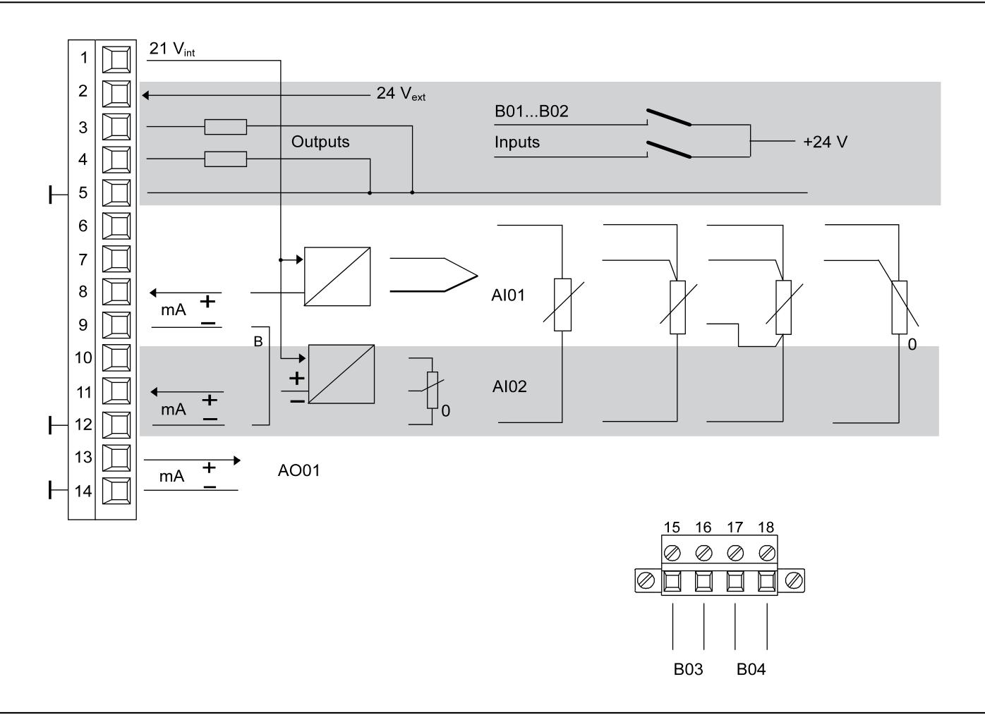
Basic version: Includes 1 universal input (supporting signals such as thermocouples, Pt100, transmitters, etc., with built-in standard sensor linearization table), 1 mA input (can be used as feedforward or setpoint input, and position feedback in stepper controllers), 1 mA output (for positioning signals, etc.), 2 configurable binary inputs/outputs, 2 relays (for executing signals, alarm outputs, etc.), and 4 module slots for expanding functions.
Programmer: Each controller includes a configurable programmer that can preset time related settings, store up to 10 programs, and each program contains 15 segments.
Controller output types: including two-point PID control, hot off cold control, step control, continuous control (optional split range output), etc.
Parameters and Configuration: Parameter settings require entering the password protected parameter level through the menu key; The configuration methods include list configuration (selecting standard functions from the built-in list of the device, which can be operated through IBISRR computer program) and free configuration (allowing customers to specific configurations, which can be added with logic control through the function plan editor).
Installation process
Model identification: Identify the model through the side nameplate.
Installation location: Suitable for front installation in control rooms, control cabinets, and machines, ensuring that it does not exceed the climate and mechanical capacity limits specified in the “Technical Data”.
Installation steps:
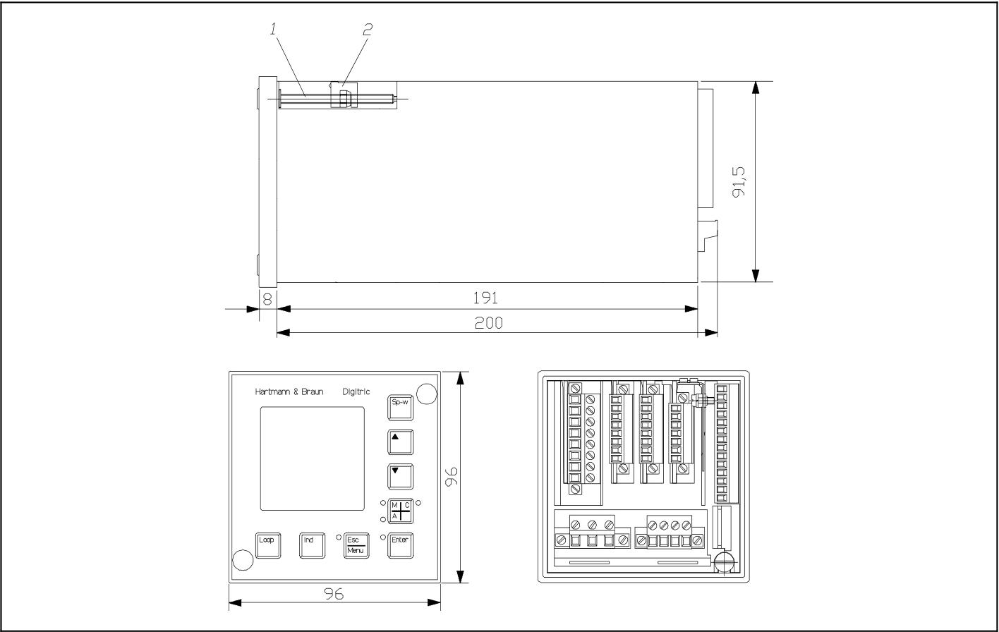
Panel opening: It must comply with DIN 43700 standard, with dimensions of 92+0.8mm × 92+0.8mm. When installed horizontally and tightly, the strip width should be at least 10mm, and at least 40mm ventilation space should be reserved above and below.
Fixed equipment: Remove the front panel dust cover, rotate the clamping claw screw counterclockwise until the clamping claw can be inserted into the panel, push the module into the panel opening, then rotate the screw clockwise to fix it, and finally reinstall the dust cover.
Connection instructions
Signal connection (basic model): using plug-in screw terminals, supporting solid or multi strand wires (maximum wire cross-section of 1.5mm ², maximum relay of 2.5mm ²), including interfaces for power connection, analog input/output, binary input/output, relay output, etc., with relay output up to 250V AC, 1A (cos φ=0.9).
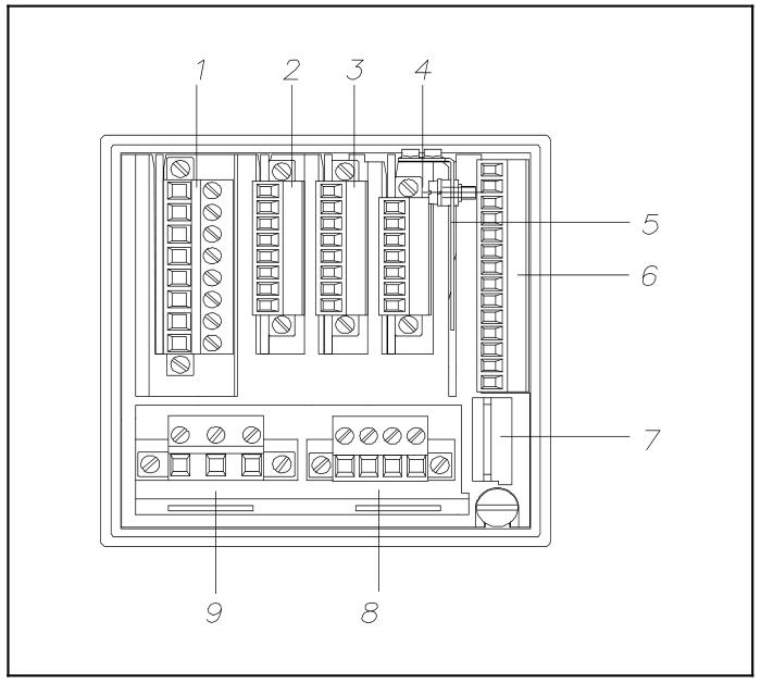
Module and computer connection: The backend includes shielded terminal boards, basic model signal connections, computer ports (configuration interfaces), relay outputs, power supply, and other interfaces.
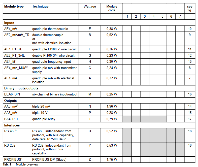
Module type and configuration
Available modules: including various analog input modules (such as 4 x mA, 2 x mA/thermocouple/mV, 4 x thermocouple, 4 x Pt100, etc.), binary input/output modules (6 channels), analog output modules (3 x mA, 3 x V), digital output modules (4 x relays), interface modules (RS-485, RS-232, PROFIBUS DP slave), etc., with a total of 4 module slots. There are no fixed slot restrictions for module allocation except for interfaces and relays.
Module installation and replacement: Before installation, all hazardous voltages need to be disconnected. Remove the sub component by rotating the twisting screw of the sub component, insert the module into the guide slot from above and install it on the bus PCB, then push back the sub component and lock it; The installation and disassembly of the bus PCB require the use of a screwdriver to operate the snap fastener.
Power supply and grounding
Power connection: Supports 115/230V AC (90-260V, 47-63Hz) or 24V UC. Please follow the relevant power installation specifications and connect the protective grounding conductor before connection. The 24V power supply also needs to be connected to the grounding conductor.
Shielding treatment: A shielding terminal board needs to be installed to fix the shielding layer of the data cable on the contact surface. If there are auxiliary wires in the shielding layer, they can be connected to the terminal.
Technical Parameter
Input: Universal input resolution of 12 bits, measurement tolerance ≤ 0.2% (relative to nominal range), temperature impact ≤ 0.2%/10 ℃; Binary input/output is configurable, with a nominal input level of 24V DC and a maximum output of 100mA.
Output: Analog output 0/4… 20mA (maximum 750 Ω, short circuit and open circuit protection), resolution of 12 bits; The maximum output of the relay is 250V AC, 1A.
Environmental conditions: working temperature 0… 50 ℃, storage temperature -20… 70 ℃, relative humidity ≤ 75% (annual average), short-term up to 95% (slight condensation allowed); Meets EMC related standards and has strong anti-interference ability.
Mechanical parameters: front panel protection level IP65, shell IP30, terminal IP20; The panel size is 96mm × 96mm, the installation depth is 200mm, the weight is 1kg (without modules), each module weighs about 40g, and the relay module weighs about 80g.
Other information
Firmware upgrade and configuration: The firmware can be updated by replacing the IC. To enable free configuration, a specific IC is required. If the password is lost, it can be reset by adjusting the jumper.
Packaging and Accessories: Insulation and buffering should be done for transportation or return packaging. Accessories include various modules, bus PCBs, PC cables, adapters, etc. Please refer to the catalog number when ordering.
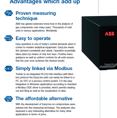
EasyLine is a new gas concentration monitoring equipment series launched by ABB, aimed at providing simple, economical, and reliable gas analysis solutions for various application scenarios. Its core advantages include:
Mature technology: Based on ABB’s years of experience in gas composition analysis, the product technology is mature and has been widely applied worldwide.
Easy to operate: Basic operations can be achieved through 4 buttons, menu navigation is clear, and all device control methods are unified, making it easy for users to quickly get started.
Easy to connect: Integrated with RS 232/485 interface and supporting Modbus protocol, it can easily connect with computers, SPC or process control systems. It also provides Modbus DDE driver for easy data reading, storage and visualization in Windows applications.
High cost-effectiveness: With competitive prices while ensuring that measurement technology is not discounted, it is an economical choice for various application scenarios.
Main product models and technical parameters
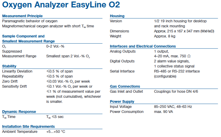
Oxygen analyzer (EasyLine O ₂)
Measurement principle: Based on oxygen paramagnetism, using magneto mechanical principle, with short response time.
Measurement range: The minimum measurement range is O ₂ 0-2 Vol. -%, supporting a suppression measurement range with a minimum span of 2 Vol. -% O ₂.
Stability: Linear deviation ≤ 0.5% of span, repeatability ≤ 0.5% of span, zero drift ≤ 0.03 Vol. -% O ₂/week, sensitivity drift ≤ 0.1 Vol. -% O ₂/week or ≤ 1% measurement value/week (whichever is smaller, not cumulative).
Dynamic response: T ₉₀ time ≤ 5 seconds.
Installation environment: ambient temperature+5…+50 ° C.
Equipment specifications: Adopting a 1/2 19 inch casing, supporting desktop and rack installation, with dimensions of approximately 215 x 167 x 347 mm (width x height x depth) and a weight of approximately 8 kg.
Interface and connection: 1 channel 4-20 mA analog output (maximum 750 Ω), 2 channels of alarm value signal and 1 channel of collective status signal digital output, supporting RS-485 or RS-232 interface (configurable).
Gas connection: The inlet and outlet ports are equipped with DN 4/6 hoses.
Power supply: Input voltage 85-250 VAC, 48-63 Hz, maximum power consumption 90 VA.
Infrared gas analyzer (EasyLine IR)
Measurement principle: Infrared photometer can measure 1 or 2 components. If used in conjunction with an electrochemical oxygen sensor, it can only measure 1 infrared gas component.
Measurement range: The measurable gases and minimum measurement range include CO 0… 500 ppm, CO ₂ 0… 500 ppm, SO ₂ 0… 500 ppm, CH ₄ 0… 500 ppm, NO 0… 1000 ppm. It can also be combined with O ₂ (0… 5 vol. -%) for measurement (specific combinations are shown in the document table).
Stability: Linear deviation ≤ 1% of span, repeatability ≤ 0.5% of span, zero drift ≤ 1% of span/week, sensitivity drift ≤ 1% of measured value/week.
Dynamic response: T ₉₀ time ≤ 2 seconds (O ₂ sensor ≤ 30 seconds).
Installation environment: ambient temperature+5 to+45 ° C (+5 to+40 ° C with O ₂ sensor).
Equipment specifications: Same as oxygen analyzer, 1/2 19 inch casing, size approximately 215 x 167 x 347 mm, weight approximately 8 kg.
Interface and Connection: Each sample component has 1 analog output and 2 digital outputs of alarm value signals, supporting RS-485 or RS-232 interfaces (configurable).
Gas connection: The inlet and outlet ports are equipped with DN 4/6 hoses.
Power supply: Input voltage 85-250 VAC, 48-63 Hz, maximum power consumption of 40 VA.
Thermal conductivity gas analyzer (EasyLine TC)
Measurement principle: Based on the difference in thermal conductivity of different gases, micro mechanical thermal conductivity analysis technology is used, which has a short response time and is less affected by temperature.
Measurement range: It can measure various gas combinations and the minimum measurement range, such as CO ₂ in N ₂ 0… 10 Vol. -%, CH ₄ in N ₂ 0… 6 Vol. -%, etc. (see document table for details), supporting suppression of measurement range.
Stability: Linear deviation ≤ 2% of span, repeatability ≤ 1% of span, zero drift ≤ 2% of minimum given measurement range/week, sensitivity drift ≤ 0.5% of minimum given measurement range/week.
Dynamic response: T ₉₀ time ≤ 2 seconds.
Installation environment: ambient temperature+5…+50 ° C.
Equipment specifications: Same as the two analyzers mentioned above, with a 1/2 19 inch casing, dimensions of approximately 215 x 167 x 347 mm, and a weight of approximately 8 kg.
Interface and connection: 1 channel 4-20 mA analog output (maximum 750 Ω), 2 channels of alarm value signal and 1 channel of collective status signal digital output, supporting RS-485 or RS-232 interface (configurable).
Gas connection: The inlet and outlet ports are equipped with DN 4/6 hoses.
Power supply: Input voltage 85-250 VAC, 48-63 Hz, maximum power consumption of 40 VA.
Typical application scenarios
This series of analyzers is widely used, including but not limited to:
Heat treatment (CO, O ₂)
Combustion process (CO)
Biological fermentation tank (CO ₂, O ₂)
Biogas (CO ₂, CH ₄)
Storage bin monitoring (CO, CH ₄)
Wastewater treatment (CO ₂)
Environmental air monitoring for buildings, tunnels, etc. (CO ₂ CO)
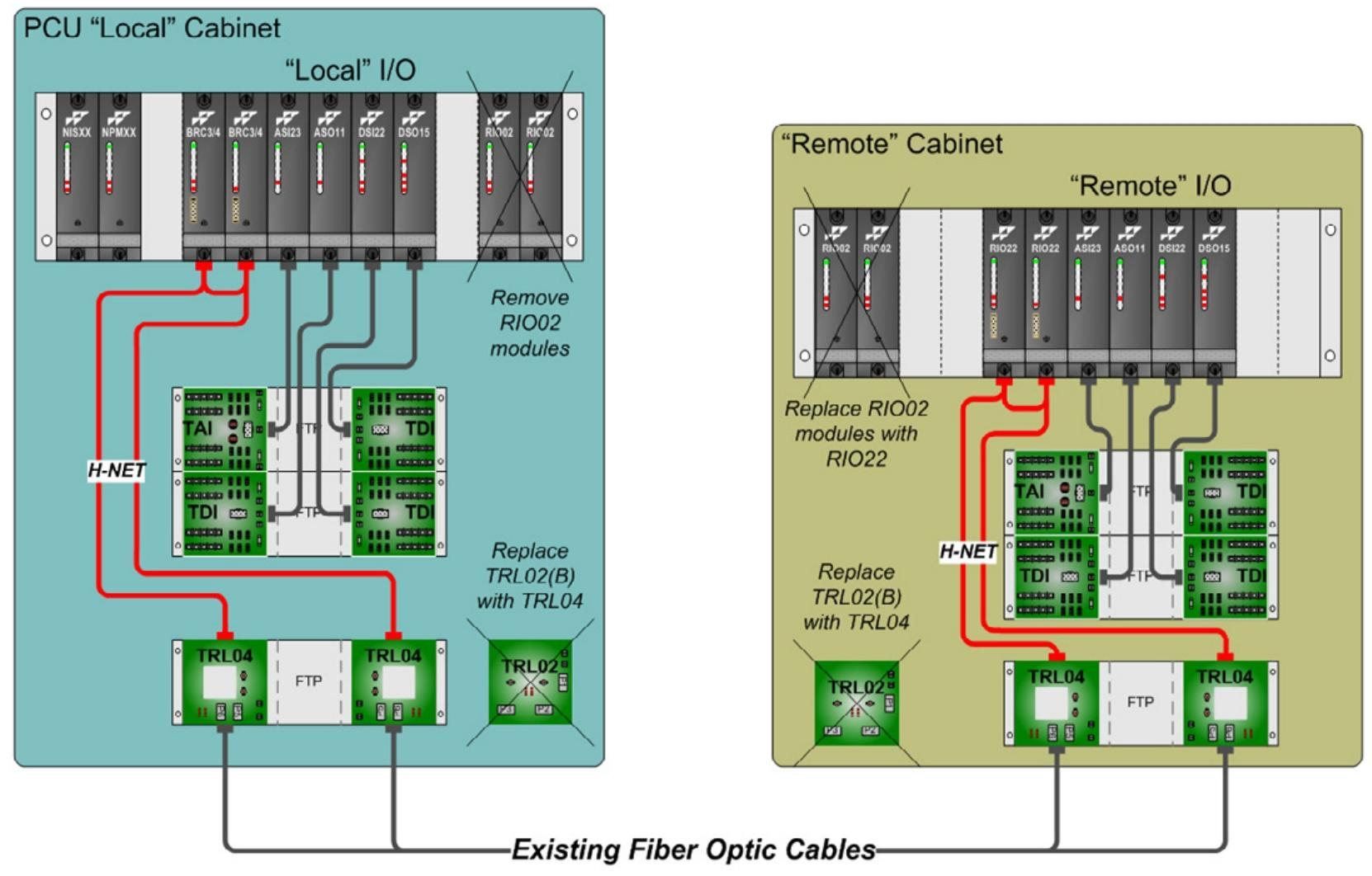
This upgrade kit is part of ABB’s lifecycle support for Symphony Harmony/INFI 90 process control systems, with the core component being a new low-cost IMRIO22 module designed to address the following issues:
Components are outdated and new parts are difficult to obtain
High cost of parts replacement and decreased maintenance capability
Electrical remote communication chain is affected by noise and lightning strikes
Difficulty in troubleshooting remote I/O issues
Slow communication link speed and time-consuming I/O point updates
Controller configuration requires special “tuning” using multiple control blocks
IMRIO02 has firmware compatibility issues with some I/O modules
System component replacement requires extra caution
The advantages of upgrading the kit
Reliability Enhancement: Adopting updated technologies to improve fiber optic communication and reduce interference effects.
Spare parts availability: Provide brand new replacement parts to address outdated issues.
Easy installation: compatible with existing remote I/O settings, with the same rack size, can reuse existing fiber optic cables, IMRIO22 directly replaces RIO02 in remote cabinets.
Space optimization: RIO02 no longer needs to be used in the local cabinet, and its functions are integrated into BRC300/400 (replacing MFP or MFC controllers in the local cabinet), reducing cabinet footprint.
Performance Enhancement: Increased memory capacity, improved execution and communication speed, faster communication link and remote I/O update speed.
Compatibility and maintainability: Improve the hardware/firmware compatibility of remote I/O processors and modules. The IMRIO22 module uses flash memory, making firmware upgrades easier.
Redundancy and Fault Tolerance: Improved redundancy capability, faster switching between primary and backup IMRIO22, enhanced error detection and diagnostic functions for easy troubleshooting, and equipped with redundant HNET remote communication channels.
System requirements and limitations
Minimum system requirements:
The BRC300/400 controller needs to be equipped with a Process Bus Adapter (PBA). If it is not equipped, an additional one needs to be added
Composer engineering tool version 5.0 or higher
Remote links require the use of 62.5/125 micron multimode fiber optic cables
Restrictions:
Only fiber optic point-to-point communication links are supported, and electrical links (dual axis or coaxial cables) must be replaced with fiber optic cables
Serial or daisy chain multi drop links are not supported. Multiple remote cabinets (up to 6) require a star configuration starting from the local cabinet
Model and components of the upgrade kit
model:
INRIOK01: Suitable for non redundant configurations
NTRL04, 4, 4, HNET fiber optic repeater terminal unit
Process bus adapter cable for PMKHRMPBA1T004, 2, 2, HNET
PHAMSCTER30000, 4, 4, HNET Bus Terminators
PMKHRMBRC3000A、 0,1. Redundant cables for bridge controller
System compatibility
The remote I/O function is compatible with all existing functions of Harmony BRC300/400 and higher version controllers, including support for multiple remote I/O links, hybrid I/O types (such as IOR/S800, Harmony rack I/O, Harmony block I/O), and reuse of existing fiber optic remote link cables.
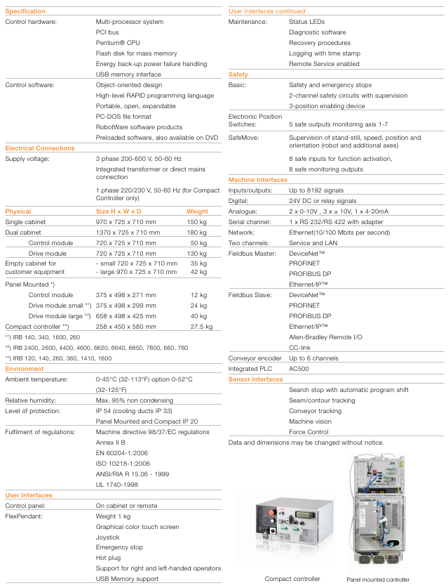
As a product based on ABB’s over 40 years of experience in robotics technology, IRC5 is centered around unique motion control technology, which combines flexibility, safety, modular design, customizable user interface, multi robot control, and PC tool support, setting an industry benchmark for industrial robot applications.
Key Features
Security: Passed third-party certification and complies with all relevant regulations. Equipped with electronic position switches and SafeMove safety systems, it achieves a new generation of safety protection and supports more flexible cell safety solutions (such as robot operator cooperation). Basic safety functions include safety emergency stop, dual channel safety circuit monitoring, and three position enabling devices.
Motion control: Based on advanced dynamic modeling, QuickMove achieves the shortest physical cycle time, TrueMove ensures precise path accuracy, and the path is independent of speed, automatically presenting predictable high-performance performance without the need for programmer debugging.
Modular design: Provides multiple variants to meet different needs, modules can be stacked, placed side by side, or distributed, optimizing footprint and cell layout. Including compact models (controlling low-end IRB series robots) and panel mounted models (inorganic cabinets, suitable for special environments).
Operation and programming: The FlexPendant interface adopts a color touch screen and 3D joystick, supporting customized applications; The RAPID programming language combines simplicity, flexibility, and powerful functionality, supporting structured programs, workshop languages, and various process applications.
Communication capability: Supports advanced I/O fieldbus and is a good node in the factory network, with functions such as sensor interface, remote disk access, socket communication, etc. Ethernet supports 10/100 Mbps, including service and LAN dual channels.
Remote services and tools: can be remotely monitored through GSM or Ethernet, providing advanced diagnostic, backup management, reporting, and preventive maintenance services; The RobotStudio tool supports online and offline processing of IRC5 data, with offline mode providing digital copies of the robot system and powerful programming and simulation capabilities.
MultiMove: A controller can control up to 4 robots, and for each additional robot, a compact drive module needs to be added to perfectly coordinate complex motion patterns.
Technical parameters
Maintenance: including status indicator lights, diagnostic software, recovery program, timestamp logging, and remote service functionality.
I/O signals: up to 8192, digital signals support 24V DC or relay signals, analog signals include 2 × 0-10V, 3 × ± 10V, 1 × 4-20mA, etc.
Fieldbus: Both master-slave modes support DeviceNet ™、 PROFINET、PROFIBUS DP、Ethernet/IP ™ It also supports Allen Bradley Remote I/O, CC link, and up to 6 channels of conveyor encoders, among other types.
Integrated PLC: AC500.
Sensor interface: supports search stop and automatic program displacement, weld/contour tracking, conveyor belt tracking, machine vision, force control, etc.
It is its original SQ-300 ® The redesign of the model, as the core component of the electrostatic precipitator (ESP) control system, can simultaneously control the dust collector, analyze alarms, and interface with computer-based data acquisition software.
With improved speed and processing capabilities, old or unreliable equipment can be replaced, helping to meet today’s government emission reporting requirements. It is also an ideal supplement to ESP upgrades and can generate key information for analyzing and improving dust collector performance.
Proven electrostatic precipitator solutions
To help keep your electrostatic precipitator (ESP) functioning at peak performance, Babcock & Wilcox Power Generation Group, Inc. (B&W PGG) provides innovative precipitator systems, mechanical and electrical components, controls and software.
New AVC design for improved performance and efficiency
B&W PGG’s SQ-300 ® i automatic voltage controller (AVC) is a redesign of our original SQ-300 ® model that has a reputation for optimizing ESP performance and collection efficiency in many worldwide industry applications.
Serving as an integral component of the precipitator control system, the SQ-300 ® i AVC simultaneously controls the precipitator, analyzes alarms, and interfaces with computer-based data acquisition software.
With its improved speed and process capability, the SQ-300 ® i controller can replace old or unreliable equipment and help maintain compliance with today’s governmental emissions reporting requirements. In addition, this versatile AVC is an ideal complement to an ESP upgrade for generating information that is critical to analyzing and improving precipitator performance.
Advanced AVC capabilities
• On-board five-trace oscilloscope permits triggering on events, such as sparking. Because the AVC cabinet can remain closed, users benefit from arc flash protection and improved personnel safety.
• Increased system flexibility provides operational benefits.
• Optional operator interface with large, color touch screen provides quick system access for simplified operation and system monitoring including VI curve, history and alarm log generation.
• Cost-effective, flexible design allows for simple or elaborate configuration.
• On-board data storage capacity for up to one year of data.
• No EEPROMs are required. Enhancements, troubleshooting and upgrades can be performed on-line and remotely from our diagnostic center.
Solid industry reputation
The SQ line of automatic voltage controls uses an advanced, patented spark response algorithm for higher performance, increased efficiency and improved emissions collection.
The SQ-300 ® i controller delivers the latest available technology and features, while maintaining the same high quality and benefits of its predecessors, the SQ-200 and SQ-300 controllers. Features include:
• Improved connectivity that interfaces with customer data acquisition systems, including Windows ® 7 operating system software
• Increased average power delivered to the field through the patented automated tuning of setback and spark rate, resulting in higher collection efficiency
• Obtains power quality analysis utilizing on-board waveform analysis
• On-board generation of Vl curves
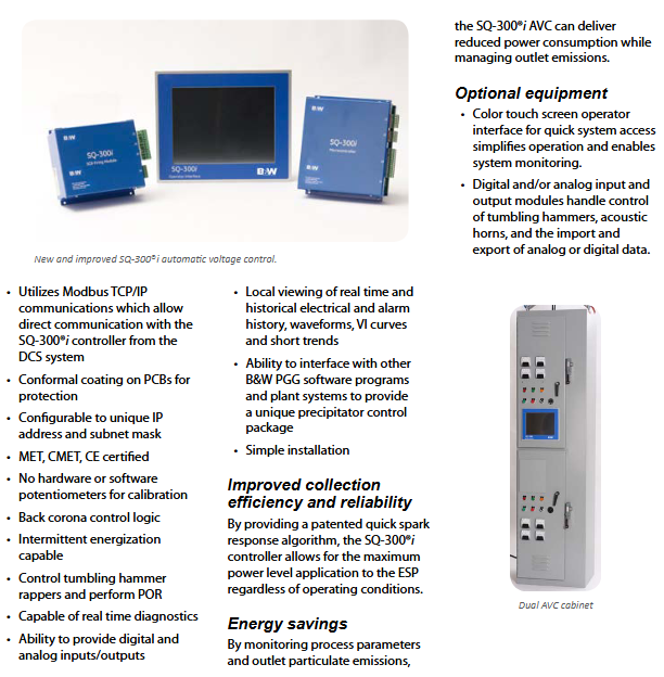
• Monitors key operations of the T/R and precipitator field during operation the SQ-300 ® i AVC can deliver reduced power consumption while managing outlet emissions.
Optional equipment
• Color touch screen operator interface for quick system access simplifies operation and enables system monitoring.
• Digital and/or analog input and output modules handle control of tumbling hammers, acoustic horns, and the import and export of analog or digital data.
• Utilizes Modbus TCP/IP communications which allow direct communication with the SQ-300 ® i controller from the DCS system
• Conformal coating on PCBs for protection
• Configurable to unique IP address and subnet mask
• MET, CMET, CE certified
• No hardware or software potentiometers for calibration
• Back corona control logic
• Intermittent energization capable
• Control tumbling hammer rappers and perform POR
• Capable of real time diagnostics
• Ability to provide digital and analog inputs/outputs
• Local viewing of real time and historical electrical and alarm history, waveforms, VI curves and short trends
• Ability to interface with other B&W PGG software programs and plant systems to provide a unique precipitator control package
• Simple installation
Improved collection efficiency and reliability
By providing a patented quick spark response algorithm, the SQ-300 ® i controller allows for the maximum power level application to the ESP regardless of operating conditions.
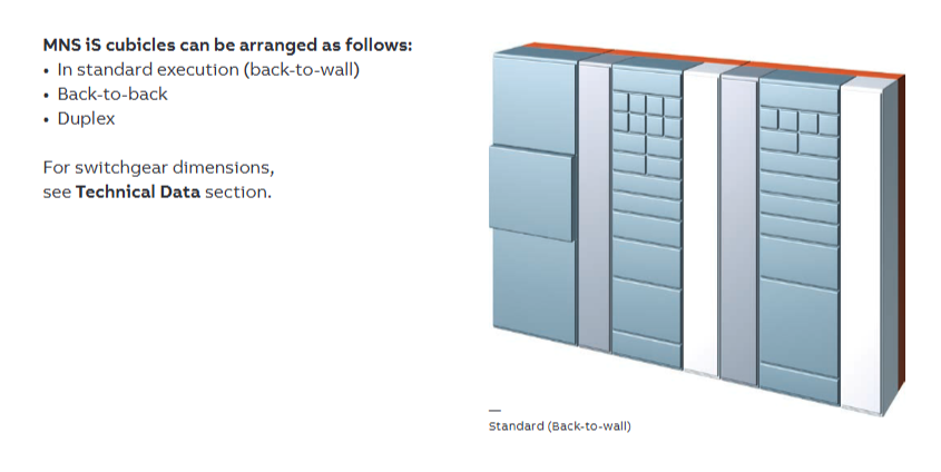
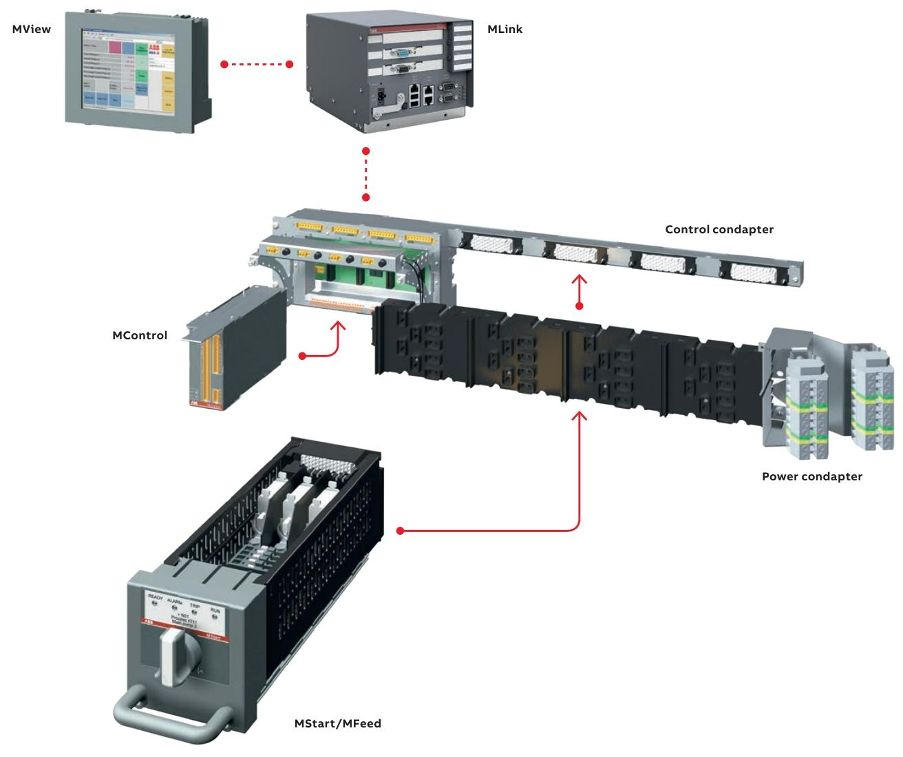
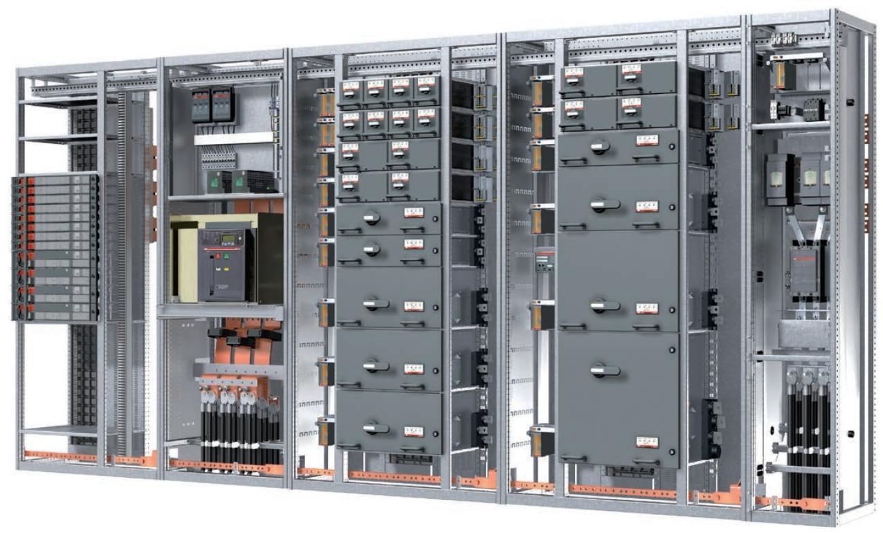
Product positioning: MNS iS is an intelligent motor control center upgraded based on MNS series technology, integrating protection, control, and monitoring functions, suitable for industrial production lines, energy facilities, and other scenarios. Through modular design, it achieves efficient operation and maintenance as well as full lifecycle cost optimization.
Core characteristics and values of the system
1. Core advantages
High safety: The power and control areas are physically isolated, complying with the IEC 61439 series standards, supporting arc fault protection (up to 100 kA/300 ms), ensuring the safety of personnel and equipment.
Standardization and flexibility: The fully pre installed power module (MStart) supports multiple starter types (direct start, star delta start, etc.), and the control module (MControl) can expand its functionality through software configuration without the need for additional hardware.
Low lifecycle cost: Reduce downtime through predictive maintenance (condition monitoring), standardize modules to lower inventory requirements, and simplify troubleshooting processes.
Intelligent information management: integrates web servers with industrial communication protocols (Profibus, Profinet, etc.), supports remote monitoring and data analysis, and achieves digital operation and maintenance.
2. Innovative design
Functional module separation: The power module (MStart) and control module (MControl) operate independently, supporting live module replacement and improving system availability.
Transformer free sensing technology: high-precision shunt sensors are used to measure current, voltage, and temperature, replacing traditional transformers and reducing energy consumption and space occupation.
Plug and play architecture: modules automatically identify location and type, communication networks automatically configure, reducing engineering complexity.
System Architecture and Components
1. Hardware composition
Power module (MStart):
Includes isolators, short-circuit protection devices (fuses or circuit breakers), contactors, and sensor modules.
Supports drawer style (6E/4 to 24E sizes) and fixed style (suitable for motors ≥ 250 kW) installation, compatible with voltage levels of 400 V, 500 V, and 690 V.
Control module (MControl):
The core controller is responsible for protecting algorithms (overload, phase loss, ground fault, etc.), logic control, and data acquisition.
Support the expansion of I/O interfaces (digital, analog, PTC/PT100 temperature input) to meet different on-site signal requirements.
Communication and Interface Module:
MLink: As a gateway connecting upper level systems, it supports protocols such as Profibus DP, Profinet, Modbus, and has a built-in web server.
MView: Local Human Machine Interface (HMI), supports touch operation and status monitoring, and can be accessed remotely through the network.
2. Structural design
Partition separation: Vertical and horizontal partitions strictly distinguish equipment areas, control cable areas, power cable areas, and busbar areas to avoid electromagnetic interference, and support different key lock control access permissions.
Busbar system: The main busbar is located at the rear of the cabinet and adopts a maintenance free design (copper material, optional silver plating or insulation sleeve). It is safely isolated from the equipment area through a multifunctional isolation wall (MFW).
Cable management: Power and control cable partition wiring, supporting up and down incoming lines, suitable for different installation scenarios.
Control and protection functions
1. Protection function module
Thermal Overload Protection (TOL): Based on the IEC 60947-4-1 standard, it calculates the motor’s thermal capacity, provides “trip time” and “reset time” warnings, and supports ATEX certification scenarios.
Motor abnormal protection: monitors phase loss, current imbalance, undervoltage, grounding faults, etc., and can be configured with alarm or trip actions.
Process monitoring and protection: including blockage, underload, no-load, and limit of starting times, to prevent mechanical failures (such as pump cavitation).
2. Maintenance and status monitoring
Predictive maintenance: Monitor parameters such as the number of contactor actions, module insertion times, operating hours, and contact temperature, and trigger an alarm when the threshold is exceeded.
System self diagnosis: Automatically verify module type and position matching, communication status, and control voltage to ensure system integrity.
Communication and Integration
Communication architecture and core components
1. Communication nodes and hierarchy
The communication system of MNS iS adopts a distributed architecture and is divided into three levels of nodes:
On site level: With MControl as the core, responsible for the protection, control, and data acquisition of a single motor, communicating with the power module (MStart) through an internal bus.
Network level: Multi node aggregation is achieved through MLink gateway, supporting interaction with upper level systems, and can connect up to 60 MControl modules.
Monitoring level: Integrated MView local human-machine interface and web server, supporting remote access and configuration.
2. Key communication components
Component Function Description
MControl has a built-in communication interface that supports real-time data exchange with MStart modules (current, temperature, status, etc.) and can be directly connected to Profibus DP/Profinet networks.
As a system gateway, MLink supports protocols such as Profibus DP, Profinet, Modbus RTU/TCP, OPC, etc., enabling integration with PLC, SCADA and other systems, while also providing web server functionality.
MView local touch panel (optional), displaying motor status, alarm information, and operation buttons based on a web interface, supporting permission management.
Communication Protocol and Interface
1. Supported protocol types
Industrial bus protocol:
Profibus DP/DP V1 (slave mode, supporting process data and diagnostic information transmission);
Profinet I/O (compatible with ABB systems and supports real-time communication);
Modbus RTU (serial communication) and Modbus TCP (Ethernet communication).
General Agreement:
Built in web server, supporting access to monitoring interface through standard browsers;
OPC interface, easy to integrate with third-party SCADA or MES systems;
NTP (Network Time Protocol) enables system wide time synchronization.
2. Data transmission capability
Internal communication: A 10 Mbps real-time bus is used between MControl and MLink, with a command response time of approximately 2 ms for a single MControl and a total system response time of ≤ 258 ms for 60 nodes.
External interaction:
The maximum transmission rate of Profibus DP is 12 Mbps;
Profinet and Modbus TCP support 100 Mbps Ethernet transmission;
Support data block read and write (such as motor current, temperature, tripping reasons, etc.) and remote control commands (start/stop/reset).
System integration capability
1. Integration with upper level systems
Process Control System (PCS): Using MLink as a gateway, the motor status and measurement values (current, power, energy consumption) are uploaded to PLC or DCS, and control instructions are received to achieve remote operation.
Electrical network monitoring system: supports sending electrical parameters (such as harmonics and power factor) to the energy management system (EMS) to assist in energy optimization.
Maintenance management system: Push equipment health data (contactor action frequency, operating hours, temperature trend) to CMMS (computerized maintenance management system) through OPC interface, supporting the development of predictive maintenance plans.
2. Redundancy and reliability design
Dual redundant communication: supports two independent communication paths (primary/backup MLink). When the primary link fails, it automatically switches to the backup link to ensure uninterrupted operation, with a switching time of ≤ 100 ms.
Communication fault protection: Configure the “fail safe” mode (such as keeping the motor running/stopping in case of communication interruption) to avoid unexpected shutdowns caused by network issues.
Time synchronization and data consistency
Synchronization mechanism: Implement system wide time calibration through NTP protocol, support access to factory level time servers (such as GPS synchronization sources), and ensure that the timestamp accuracy of event records (alarms, trips) is ≤ 1 ms.
Data timeliness: The update cycle of key measurement values (such as current and temperature) can be configured (default 100 ms) to meet real-time monitoring requirements; Historical data (energy consumption, number of actions) is stored at the minute level and supports trend analysis.
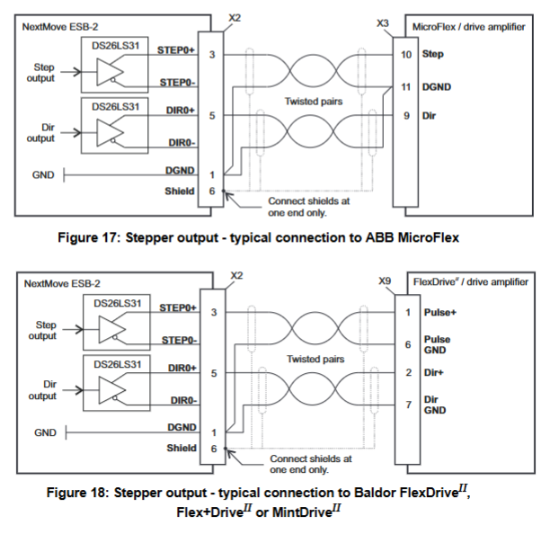
Product positioning: NextMove ESB-2 is a high-precision multi axis intelligent controller that supports servo motor and stepper motor control. It is suitable for automated production lines, precision machinery, and other scenarios, and uses Mint programming language to achieve complex motion control (such as point-to-point motion, electronic gears, cam synchronization, etc.).
Product Overview and Core Features
1. Model and classification
According to the number of servo axes, serial interface type, and stepper output type, there are 8 models, with the following core differences:
Model series, number of servo axes, number of stepper axes, additional encoder input, serial port, stepper output type
NSB202、3、4、2、RS232/485、 Differential Output
NSB203、3、4、2、RS232/485、 open collector
NSB204、4、4、1、RS232/485、 Differential Output
NSB205、4、4、1、RS232/485、 open collector
2. Core functions
Multi axis control: Supports 4 stepper axes+3/4 servo axes (model dependent), supports complex motion modes such as master-slave following and electronic gears.
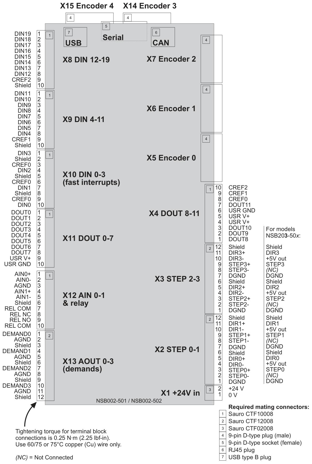
Rich I/O interfaces: 20 digital inputs, 12 digital outputs, 2 12 bit analog inputs, 4 12 bit analog outputs, suitable for various sensors and actuators.
Communication capability: comes standard with USB 1.1, RS232/RS485, CANopen (compatible with third-party devices), and Baldor CAN (proprietary protocol).
Programming flexibility: Based on Mint language (Structured Basic), it supports rapid development of simple motion programs and complex synchronous control logic.
Hardware and interface configuration
1. Power supply and installation
Power supply requirements:+24V DC (± 20%), continuous current of 2A, it is recommended to configure an independent power supply with 4A fuses.
Installation environment: Operating temperature of 0-45 ℃, relative humidity ≤ 80% (no condensation), vertical installation on non flammable surfaces, with a reserved heat dissipation space of ≥ 20mm around.
Mechanical dimensions: 245mm × 140mm × 45mm, weighing approximately 700g, fixed with M4 screws.
2. Key interface parameters
Analog input: differential input, ± 10V range, 12 bit resolution, input impedance of 120k Ω, maximum sampling rate of 4kHz
Analog output: Single ended output, ± 10V range, 12 bit resolution, maximum output current of 2.5mA, update frequency up to 10kHz
Digital input: Optocoupler isolation, supports level/edge triggering, 3 sets of common terminals (CREF0/1/2), input voltage 12~30V DC
Digital output: Maximum total current 500mA (DOUT0-7)/500mA (DOUT8-11), supports driving relays, solenoid valves, etc
Encoder input: Supports 5 incremental encoders (A/B/Z phase), RS422 differential signal, maximum input frequency 10MHz
CAN interface: Supports CANopen and Baldor CAN protocols, with a maximum baud rate of 1Mbps, requiring 12-24V power supply (optocoupler isolation)
Serial interface: RS232 (up to 115.2KBaud)/RS485 (supports multi machine cascading), USB 1.1 (compatible with USB 2.0/3.0)
Software and Programming Guide
Development Environment and Tools
1. Core software components
Mint WorkBench: An integrated development environment (IDE) used for programming, debugging, parameter configuration, and motion monitoring, supporting Windows XP and above systems (32/64 bit). The main functions include:
Code editing and syntax checking
Real time data collection and graphical display (position, velocity, current, etc.)
Axis parameter configuration and servo tuning
Firmware Update and System Diagnosis
Mint Machine Center (MMC): Used for managing multi controller networks, supporting scanning and connecting multiple NextMove ESB-2 nodes, creating visual system layouts, and saving workspace configurations.
2. Software installation and connection
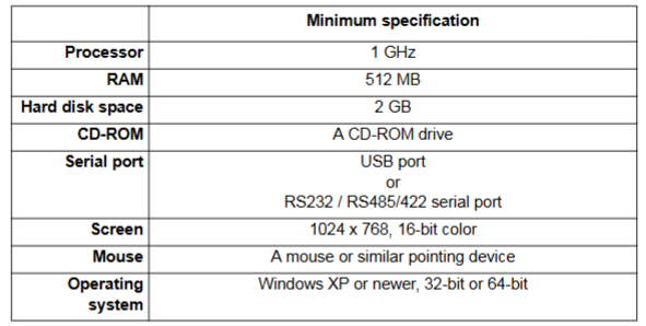
Installation requirements: The PC must meet the minimum configuration (1GHz processor, 512MB memory, 2GB hard disk space, USB or serial port), and administrator privileges are required for installation.
Connection method:
USB: Connect directly through USB Type B interface and automatically install drivers (compatible with Windows XP/Vista/7).
Serial port: RS232 (maximum 3m cable) or RS485 (supports multi machine cascading, requires terminal resistance matching).
Network: Connect distributed nodes through CANopen or Baldor CAN protocol.
Fundamentals of Mint Programming Language
Language characteristics
Mint is a structured language designed specifically for motion control, based on Basic syntax and extending motion control specific commands. Its features include:
Multi axis support: Control objects are distinguished by axis numbers (0-7), and multiple axes can be operated simultaneously.
Real time performance: The cycle time can be configured (1ms or 2ms) to ensure efficient execution of motion instructions.
Rich library functions: covering specialized commands such as point motion, speed control, synchronous following, etc
PFCL 201 series sensors are based on Presductor ® High precision force measurement equipment for technology is mainly used for tension detection of coils (such as paper, metal strips, plastic films) in medium and high voltage industrial environments. By measuring the vertical reaction force generated by coil tension, precise control of the production process is achieved.
Product Overview and Core Features
1. Model and classification
The PFCL 201 series includes three models, divided by structure and environmental adaptability:
PFCL 201C: Basic model, equipped with detachable cable connectors, suitable for conventional environments;
PFCL 201CE: Cable with fixed protective hose, enhanced mechanical protection, suitable for vibration scenarios;
PFCL 201CD: Made of acid resistant PTFE insulated cable and stainless steel material (1.4404), suitable for corrosive environments.
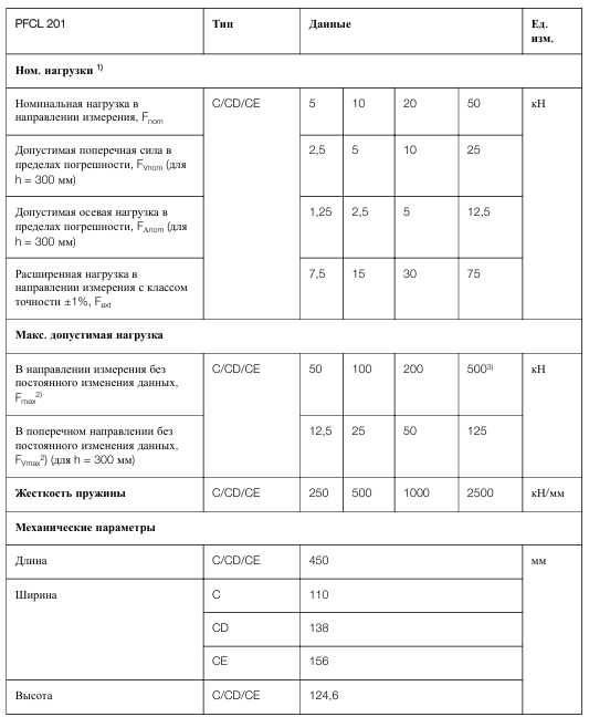
All three models support four ranges of 5kN, 10kN, 20kN, and 50kN, meeting the needs of different tension scenarios.
2. Measurement principle
Based on the magnetostrictive effect: The sensor core is a magnetostrictive diaphragm integrated in a steel block. The primary winding is fed with 330Hz AC power to generate a magnetic field, and the secondary winding induces a voltage signal proportional to the tension due to mechanical force. It is only sensitive to forces in the vertical direction (measurement direction) and has strong anti-interference ability against lateral and axial forces (with an allowable error of ≤± 0.5%).
3. Key technical parameters
Parameter specification range
Accuracy level ± 0.5% FS
Linear deviation<± 0.3% FS
Lag error<0.2% FS
Working temperature range -10~+90 ℃
Compensation temperature range+20~+80 ℃
Overload capacity (without permanent deformation) 10 times the rated load (up to 500kN for 50kN models)
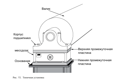
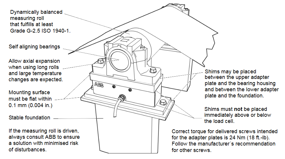
The sensor is fixed with 4 M16 screws (recommended 12.9 grade alloy screws, torque 170-286Nm) to avoid deformation of the base due to over tightening;
Horizontal or inclined installation is allowed (inclination angle ≤ 30 °), and the measurement force needs to be corrected through the angle compensation formula when tilting (see manual 2.5.3).
Electrical connection:
The cable needs to be twisted pair shielded, with the shielding layer grounded at one end (length ≤ 50mm) and a distance of ≥ 30cm from the power cable;
The primary winding provides a power supply of 0.5A/330Hz, and the secondary signal output impedance is 9-12 Ω, with strong anti-interference ability.
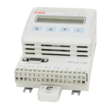
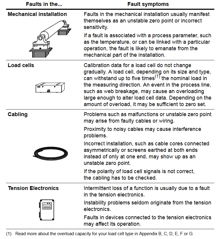
PFEA111/112 is based on Presductor ® A high-precision tension measurement and control system for technology, used for tension detection and control in the production process of coil materials such as paper, metal strips, and plastic films. Among them, PFEA111 is the basic model, and PFEA112 adds Profibus DP communication function, which is widely used in industries such as papermaking, printing, and metallurgy.
System composition and core technology
1. System composition
Core components: Tension electronic unit (PFEA111/112), weighing sensors (such as PFCL 301E, PFTL 301E, PFRL 101, etc.), junction box (PFXC 141), power module and communication interface (PFEA112 including Profibus DP).
Measurement principle: Based on the magnetostriction effect, the sensor core is a stacked alloy sheet. A 330Hz AC current is passed through the primary winding to generate a magnetic field. The secondary winding induces a voltage signal proportional to the tension due to mechanical force, and has strong resistance to lateral and axial force interference (error ≤± 0.5%).
2. Core Features
Functional differences:
PFEA111: Provides analog output (voltage/current), supports basic tension measurement and control.
PFEA112: Add Profibus DP communication on the basis of PFEA111, supporting remote data transmission and control.
Multi scenario adaptation: Supports single roll (1-2 sensors) and double roll (up to 4 sensors) applications, adapting to multiple types of weighing sensors.
High reliability: equipped with overvoltage, overcurrent, and overtemperature protection, supporting fault self diagnosis, with a protection level of IP20 (DIN rail installation) or IP65 (wall mounted).
Installation and wiring specifications
1. Installation environment requirements
Physical environment: Operating temperature -10~+55 ℃ (IP20), -25~+70 ℃ (IP65), relative humidity ≤ 95% (no condensation), avoid strong electromagnetic interference sources (such as frequency converters).
Mechanical requirements: The flatness error of the installation surface should be ≤ 0.1mm, and the gap between the sensor and the adapter board should be clean and free of debris to ensure accurate force transmission.
2. Hardware wiring
Sensor wiring:
The analog signal adopts twisted pair shielded cable, with the shielding layer grounded at one end (length ≤ 50mm) and a distance of ≥ 30cm from the power line.
The maximum allowable cable resistance of the sensor excitation circuit is ≤ 5 Ω, which needs to be measured and confirmed before debugging.
Power and Communication:
The power supply supports wide range input (IP20: 24V DC; IP65: 85-264V AC or 24V DC), with a power consumption of ≤ 8W.
The Profibus DP interface of PFEA112 supports a maximum transmission rate of 12Mbps and requires the use of a dedicated bus cable (impedance 150 Ω) with terminal resistors at both ends.
Debugging and configuration process
1. Basic settings
Quick configuration: Set the language (English/German/French, etc.), unit (N/kN/kg, etc.), and web width (applicable to N/m, etc.) through panel buttons, and support fast zero calibration and wrrap gain calculation.
Complete configuration: including system definition (single roll/double roll), sensor type selection, nominal load setting, zero calibration, and calculation of wrrap gain (derived from suspension weight or formula).
2. Key parameter configuration
Wrap gain: the ratio of tension (T) to sensor measured force (FR), calculated as Wrap gain=T/FR, which needs to be derived through geometric relationships based on the installation angle (horizontal/inclined).
Communication settings (PFEA112): Profibus address (0-125), baud rate (up to 12Mbps), supports real-time data exchange with PLC or SCADA systems.