Call us 24/7uaedcs@163.com
Welcome to the official website of CNIACS Automation Technology Co., Ltd!
Call us 24/7uaedcs@163.com

ALSTOM N70032702L High Performance Control Module

The ALSTOM N70032702L high-performance control module is a core component developed by ALSTOM for complex industrial control scenarios. It integrates advanced microelectronics technology and intelligent control algorithms, aiming to provide high-precision and high reliability control solutions for fields such as power, rail transit, and industrial automation. As the flagship model of ALSTOM’s industrial control product line, this module achieves collaborative control and real-time monitoring of multiple types of equipment through modular design and open architecture, improving system efficiency while reducing operational complexity.

Product positioning and architecture design

(1) Core positioning

The N70032702L module is positioned as the “nerve center” of industrial automation systems, mainly responsible for three core functions: data processing, logical operations, and equipment control. It adopts a 32-bit high-performance processor, combined with a real-time operating system (RTOS), which can achieve fast response to millisecond level signals and is suitable for key control scenarios that require high real-time performance, such as power grid relay protection, train traction control, and large-scale unit linkage control.

(2) Hardware architecture

Processing Unit: Equipped with an ARM Cortex-A53 processor with a main frequency of 500MHz, integrated with 1MB cache, supporting floating-point operations and digital signal processing (DSP) instruction sets, with a data processing capacity of 200MIPS (millions of instructions per second).

Storage system: Comes standard with 2GB DDR4 memory and 16GB eMMC flash memory, supports external SD card expansion to 128GB, meeting the needs of large data storage and program operation.

Interface configuration:

Communication interface: 4-channel Gigabit Ethernet (supporting IEEE 1588 precise clock synchronization), 2-channel RS-485/RS-32 serial interface, and 1-channel CANopen bus.

Input/output: 16 digital inputs (24V DC), 12 digital outputs (relay/transistor optional), 8 analog inputs (± 10V/4-20mA), 4 analog outputs (4-20mA).

Expansion interface: 2 PCIe Mini slots (supporting PCIe 2.0 x1), 1 USB 3.0 interface.

Power supply design: Supports dual power redundant input (85-264V AC/24-110V DC), built-in UPS backup power supply (maintenance time ≥ 10 minutes), ensuring that critical data is not lost in case of power failure.

(3) Software Architecture

Operating System: Pre installed with QNX Neutrino RTOS, supporting POSIX standards, with real-time performance reaching microsecond level, capable of running over 100 task processes simultaneously.

Development Environment: Provides an Eclipse based integrated development environment (IDE) that supports C/C++and Python programming, and is compatible with importing MATLAB/Simulink models.

Protocol support: Built in industrial communication protocol stacks such as Modbus, OPC UA, IEC 61850, EtherCAT, etc., supporting custom protocol development.

Key performance parameters

Processing performance

Instruction cycle: ≤ 50ns Data throughput: 1.2GB/s

Support multitasking parallel processing, suitable for high-density data acquisition and complex algorithm computation

real-time

Interrupt response time: ≤ 1 μ s Task switching time: ≤ 2 μ s

Satisfy scenarios with high real-time requirements such as power system protection and rail transit signal control

Accuracy control

Analog acquisition accuracy: ± 0.1% Digital synchronization accuracy: ≤ 100ns

Suitable for industrial process control that requires high-precision measurement, such as precision instrument drive and motor vector control

reliability

MTBF (Mean Time Between Failures): ≥ 100000 hours Operating temperature: -40 ℃~+70 ℃ Protection level: IP54 (optional IP65)

Can operate stably in harsh industrial environments, meeting the needs of outdoor, high temperature and other scenarios

anti-interference

Electromagnetic compatibility: compliant with EN 61000-6-2/3 vibration test: 5-2000Hz, 50g acceleration

Resist the effects of electromagnetic interference and mechanical vibration in industrial sites, and ensure the accuracy of data transmission and control instructions

Typical application scenarios

(1) Power system automation

Substation comprehensive automation: As a control unit for the interval layer, it achieves precise control of circuit breakers and isolating switches, supports IEC 61850 standard and GOOSE message transmission, and seamlessly cooperates with protection devices and measurement and control devices. For example, in a 220kV substation, this module can simultaneously process 100+remote signaling signals and 50+remote measurements, control 20+switch devices, and have a response time of ≤ 10ms.

New energy grid connection control: used for real-time monitoring and power regulation of inverters in wind farms and photovoltaic power stations, supporting active/reactive power decoupling control, with a power regulation accuracy of 0.5% of rated power, meeting the grid connection technical requirements of the power grid for new energy stations.

(2) Rail Transit

Train traction control: installed in the traction converter of the high-speed train, it realizes vector control of the traction motor, with a control accuracy of 0.1Hz, supports multiple power supply modes of 1500V DC/25kV AC, and is suitable for different vehicle types such as high-speed rail, subway, and light rail.

Signal system: as an on-board signal processing unit, it interfaces with ATP (automatic train protection) and ATO (automatic train operation) systems to process trackside signal and on-board sensor data, with communication delay ≤ 5ms to ensure traffic safety and punctuality.

(3) Industrial Process Control

Intelligent manufacturing production line: In the automotive welding workshop and electronic component production line, the motion trajectory and process parameters of the robotic arm are controlled, with a positioning accuracy of ± 0.1mm. It supports seamless integration with PLC and SCADA systems to achieve flexible production.

Petrochemical control: used for closed-loop control of reaction kettle temperature and pressure in refineries, supporting complex algorithms such as cascade control and feedforward control, with a control cycle of ≤ 100ms, ensuring that process parameters are stable within the set value ± 0.5% range.

(4) Special equipment control

Aerospace ground equipment: Real time control of high-pressure fuel pumps and cooling systems is achieved at satellite launch sites and aircraft engine test benches, supporting 1553B bus protocol and data transmission error rate ≤ 10 ^ -9.

Military equipment: compatible with shipborne radar servo systems and armored vehicle fire control systems, with wide temperature range and anti vibration characteristics, meeting the reliability requirements of military equipment through GJB 150 environmental testing standards.

Core advantages of the product

(1) High performance and high integration

Multi core heterogeneous processing: Adopting a “CPU+FPGA” architecture, the CPU is responsible for logical operations and protocol processing, while the FPGA achieves high-speed data acquisition and hardware acceleration, resulting in a performance improvement of more than three times compared to traditional single core controllers. For example, in the scenario of fault recording in the power system, 128 analog signals can be collected simultaneously with a sampling rate of 100kHz, and the fault waveform can be stored and analyzed in real time.

Functional density: It integrates the functions of traditional multiple control units within a volume of 200mm × 150mm × 50mm, reducing cabinet space occupation by 30% and lowering system wiring complexity.

(2) Openness and Scalability

Open API: Provides standardized API interfaces and software development kits (SDKs), supporting third-party application development, such as allowing users to customize algorithm modules and embed them into real-time control systems.

Modular Expansion: Specialized function cards such as FPGA acceleration cards and high-speed data acquisition cards can be added through PCIe Mini slots to meet personalized needs. In a case study of a steel enterprise, direct torque control (DTC) of the main motor of the rolling mill was achieved by extending the FPGA card, resulting in a 20% improvement in control performance.

(3) Reliability and safety

Fault tolerance mechanism: Supports hot standby redundancy (1+1 redundancy mode), with a main standby switching time of ≤ 50ms, ensuring uninterrupted control tasks. Built in triple watchdog circuit to prevent program from running away.

Information security: Integrated hardware encryption chip (supporting AES-256 algorithm), realizing data transmission encryption and device identity authentication, complying with IEC 62443 industrial network security standard, defending against network attacks and data tampering.

(4) Usability and low operational costs

Visual debugging: Built in web server, real-time data and configuration parameters can be viewed through a browser, supporting remote debugging and firmware upgrades, reducing on-site maintenance workload.

Predictive maintenance: Real time monitoring of internal temperature, voltage, fan speed and other health status parameters of the module, early warning of potential faults, and reducing equipment maintenance costs by 40% in a subway project application.

Technological innovation points

Mixed signal processing technology: using a 24 bit Δ – ∑ analog-to-digital converter (ADC) combined with digital filtering algorithm, the signal-to-noise ratio of analog signal acquisition is increased to 120dB, suitable for weak signal detection, such as transformer partial discharge monitoring.

Time sensitive network (TSN) support: Integrating TSN protocols such as IEEE 802.1Qbv and IEEE 802.1AS to achieve sub microsecond level network synchronization and meet the real-time communication requirements of the Industrial Internet of Things (IIoT).

Edge computing capability: built-in machine learning inference engine, support lightweight neural network model (such as TensorFlow Lite), can directly process sensor data at the edge side, and reduce cloud data transmission by more than 50%.

ALSTOM MVAJ1L1GB0771B Auxiliary Transmission Relay

Product Overview

MVAJ1L1GB0771B auxiliary transmission relay is mainly used for auxiliary protection and control of power transmission systems. It can accurately receive various signals, and through complex internal logic operations and processing, quickly respond, thereby achieving effective control and protection of power equipment. In the power transmission network, whether it is substations, transmission lines, or various types of power users, this relay can play an indispensable role.

Performance parameters

Rated voltage: Supports multiple common rated voltage specifications, such as 24V DC, 48V DC, 110V DC, 220V DC, etc., to meet the needs of different power systems. This multi voltage specification design enables the relay to be widely used in various occasions, whether it is small power equipment or large power engineering, suitable voltage matching can be found.

Action voltage: The action voltage is usually lower than a specific value of the rated voltage, which ensures that the relay can operate accurately when the voltage fluctuates. For example, when the voltage of the power system drops slightly but remains within the normal fluctuation range, the relay will not malfunction; When the voltage drops to the threshold that affects the normal operation of the equipment, the relay can quickly respond and perform corresponding protective actions.

Reset voltage: The reset voltage is lower than a specific value of the sustain voltage. After the fault is resolved and the power system returns to normal, the relay can quickly reset under appropriate voltage conditions, preparing for the next possible task and ensuring the continuous and stable operation of the power system.

Contact type: It has multiple sets of normally open (NO) or normally closed (NC) contacts, and the specific configuration depends on different application scenarios and customer needs. Normally, normally open contacts are in an open state and close when the relay is activated; Normally closed contacts are the opposite, closed normally and open when the relay is activated. This flexible contact configuration enables relays to meet the requirements of different control logics, such as starting devices, stopping devices, and sending signals.

Contact capacity: With high breaking capacity, it can reliably drive loads such as circuit breaker trip coils. When a fault occurs in the power system, the powerful contact capacity ensures that the relay can quickly cut off the fault current, protect the power equipment from damage, and ensure the safe and stable operation of the power system.

Response time: The response time is extremely short, usually in milliseconds. In the rapidly changing power system, fast response time is crucial. When an abnormal signal is detected, the relay can react in a very short time, execute protective actions in a timely manner, and minimize the impact of faults on the power system.

Power consumption: Extremely low power consumption, meeting the requirements of modern power systems for energy conservation and efficiency. Low power design not only reduces energy consumption, but also reduces the heating problem of the relay itself, improving the reliability and service life of the equipment.

Insulation strength: meets relevant insulation standards and can effectively prevent electrical short circuits and leakage problems. In complex power environments, good insulation performance ensures the stable operation of relays, avoiding equipment failures and safety accidents caused by poor insulation.

Working temperature: The working temperature range is -25 ° C to+70 ° C, which can adapt to various harsh working environments. Whether in cold northern regions, hot southern regions, or in high-temperature industrial environments or low-temperature outdoor environments, this relay can work normally to ensure the stable operation of the power system.

Application Fields

Transmission line protection: In the distance protection and directional overcurrent protection schemes of transmission lines, the MVAJ1L1GB0771B relay receives the tripping signal of the protection relay and quickly drives the line circuit breaker to quickly cut off the fault. For example, when a short circuit fault occurs in a transmission line, the relay can detect the fault signal within milliseconds and transmit the trip signal to the circuit breaker, causing the circuit breaker to quickly cut off the faulty line, prevent the fault from expanding, and ensure the safe operation of the transmission line.

Transformer protection: In differential protection, overcurrent protection and other protection schemes for transformers, this relay is used to drive the transformer circuit breaker to trip and isolate transformer faults. When faults such as winding short circuit and overload occur inside the transformer, the relay can respond promptly by driving the circuit breaker to trip, isolating the faulty transformer from the power system and protecting the transformer and other equipment from further damage.

Generator protection: Among various protection schemes for generators, MVAJ1L1GB0771B transmits the tripping command of the protection relay to the generator outlet circuit breaker to achieve fault removal. When internal faults occur in the generator, such as stator winding short circuit, rotor grounding, etc., the relay can quickly act to trip the generator outlet circuit breaker, protecting the safe operation of the generator and avoiding serious impact on the power system.

Bus protection: In schemes such as bus differential protection, this relay is used to drive circuit breakers related to faulty bus segments to trip. The busbar is an important part of the power system for collecting and distributing electrical energy. Once the busbar fails, the consequences can be unimaginable. The MVAJ1L1GB0771B relay can quickly respond to bus faults by driving the corresponding circuit breaker to trip and isolate the faulty bus section, ensuring the stable operation of the entire power system.

Motor protection: In the protection circuit of large motors, the relay receives the tripping signal of the protection relay, drives the motor circuit breaker to trip, and protects the motor. When the motor experiences faults such as overload, stalling, and phase loss operation, the relay can detect abnormal signals in a timely manner and quickly perform tripping operations to protect the motor from damage and extend its service life.

Product advantages

Extremely low burden: The design goal is to minimize the current demand on the drive circuit, thereby reducing the burden on the output contacts of the front-end protection relay, extending its service life, and improving the reliability of the system. In the power system, the output contacts of the front-end protection relay need to operate frequently, which imposes a heavy burden. The low load characteristic of MVAJ1L1GB0771B relay effectively reduces the wear on these contacts and lowers the probability of faults occurring.

High reliability: Using high-quality components and mature designs, ensuring reliable operation under various operating conditions, executing trip instructions, and ensuring the safety of the power system. As a well-known enterprise in the industry, ALSTOM strictly controls the quality of its product manufacturing process, selects high-quality components, and has undergone extensive experiments and practical operation verification, making the relay highly reliable and capable of stable operation in complex and harsh power environments.

Quick response: With extremely fast action speed, it can quickly drive the circuit breaker to trip upon receiving a trip signal, minimizing the duration of the fault. Every second, even every millisecond, is crucial when a power system failure occurs. The fast response characteristic of this relay can timely cut off the fault current, reduce the degree of equipment damage, and minimize the impact on the stability of the power system.

Multi contact output: Provides multiple sets of normally open or normally closed contacts, which can simultaneously drive multiple circuit breaker trip coils or be used for signal indication, improving the flexibility of the system. In some complex power systems, it may be necessary to simultaneously control multiple devices or emit multiple signals. The multi contact output function of MVAJ1L1GB0771B relay can meet the diverse control requirements, making the design and operation of power systems more flexible and efficient.

Strong anti-interference ability: It has good anti-interference ability and can work stably and reliably in complex power system environments. There are various sources of electromagnetic interference in the power system, such as the starting of large motors and frequent switching of switches. This relay effectively resists electromagnetic interference through special design and technology, ensuring its normal operation and avoiding misoperation caused by interference.

Multiple rated voltage options: Provides multiple DC rated voltage specifications to meet the needs of different power systems. Different power systems may use different voltage levels, and the multi rated voltage design of this relay enables it to be widely used in various power systems without the need for complex voltage conversion, reducing system costs and complexity.

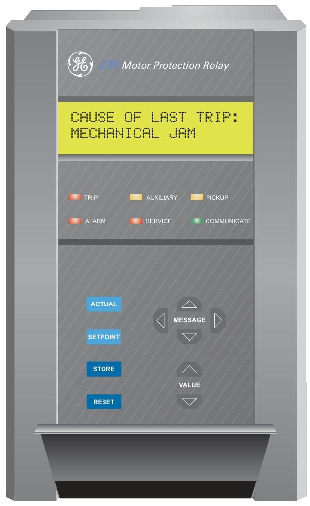
GE 239 MOTOR PROTECTION RELAY

Communication Overview

Protocol standard: Adopting a subset of the Modbus RTU serial communication standard, it is a single master multi slave protocol with 239 relays as slave devices. It does not support master mode and only supports RTU version (binary), not ASCII version.

Application scenario: Monitoring, programming, and control functions can be achieved through read and write register commands, suitable for communication scenarios with multiple device chain connections.

Hardware interface and data transmission

Electrical interface: Use a two-wire RS485 hardware interface for half duplex bidirectional data transmission, requiring a daisy chain configuration with terminal networks installed at both ends (such as Belden 9841 wire with a 120 Ω resistor connected in series with a 1nF ceramic capacitor). Use shielded wires and pay attention to polarity.

Data frame format: Asynchronous transmission, 10 bits per frame (1 start bit+8 data bits+1 stop bit), supports baud rates of 1200, 2400, 4800, 9600, 19200.

Data packet format: Both the master request and the slave response contain the slave address, function code, data, and CRC checksum. The slave address 0 is the broadcast command, and the function code>127 indicates an error response.

Error verification: CRC-16 verification is used. If the verification is incorrect, the slave device will not respond, and the algorithm involves polynomial division. Please refer to the document for specific steps.

Timing requirement: If the received character interval exceeds 3.5 characters, the communication link needs to be reset, such as exceeding 3.65ms at 9600 baud rate.

Supported Modbus Function Codes

03/04: Read set value and actual value, read up to 125 registers (hold register/input register), 16 bit value low byte priority request to read 3 registers starting from 006B at address 11

05: Execute operation, trigger relay action through operation code (such as reset, emergency restart) Reset relay (operation code 1)

06: Store a single set value, write the set value to a single register, and request the device to write 0064 to address 1020

07: Read device status, retrieve device status bytes (alarm, trip, etc. flag bits), request status from address 11

08: Loop back testing, testing communication link integrity, requesting/sending test data 0000 from the device

16: Store multiple set values, batch write up to 60 registers/write 0096 to 1028 and 1029

16 (Execute Command): Execute operations by writing registers. When the PLC does not support the 05 function code, it is necessary to write command function code 5 and operation code to address 0080 and 0081 to perform reset

Memory-mapped

User defined memory area: Address remapping is achieved through register index (0180H-01F7H) and data area (0100H-0177H) to improve data throughput, such as mapping current and temperature values of different addresses to adjacent addresses for reading.

Memory mapping table: Detailed listing of groups, descriptions, ranges, step sizes, units, etc. for each address, including 21 parts such as product information (0000-007F), commands (0080-00FF), user-defined registers (0100-017F), actual values (0200-027F), set values (1000-11EF), covering motor status, fault causes, current, temperature, relay configuration, etc.

Data format: defines the data types and bit masks corresponding to codes F1-F114, such as F1 being an unsigned integer, F5 being a trip reason code, F104 being a product option flag, etc.

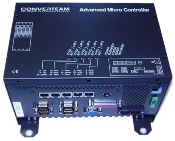
ALSTOM ADVANCED MICRO CONTROLLER 2

Description of AMC2

Controller Box Design: The main controller box for AMC-PLC, AMC-AU, and AMC-DP is designed by Converteam and supplied by Eltech, using the Arbor EmE7x-i701 controller board.

Appearance and Performance

A small and sturdy flange mounting box that can be installed on vertical panels.

The temperature rating without a fan is 70 ° C.

Through type testing, including 15g impact testing (compliant with IEC1131 standard).

Based on commercial off the shelf (COTS) Pentium M-class embedded CPU, the cost is low. Special orders can provide higher performance 1.40 GHz Pentium M.

Equipped with LED indicators for power supply and normal operation status, as well as an identity encryption dog port for defining the controller ID.

Integrated with 5 Ethernet ports and 4 serial links (RS232), 3 of which are available for application use, as well as high-density serial interfaces for ship DP.

Application areas: Used for ship architecture (DP and automation controllers, on-site station PLCs and redundant boxes), PEC drive controllers, and general PLC applications.

Technical Parameter

CPU: 600MHz Celeron M.

Memory: 256MB DRAM, 256MB Compact Flash.

Relative performance: Approximately twice that of AMC1 (depending on the application code).

Power supply: 24V DC ± 20% power supply, consuming approximately 0.9A.

Network: 5 LAN ports.

Serial: 4 serial ports.

USB: 2 (with Yamaichi latch system).

Expansion slots: 4 PMC/PC104+slots, suitable for 16 channel Serial 16+FIP, Profibus master, Profibus slave fieldbus, fiber optic Ethernet, etc.

Installation method: Panel installation.

Size: 234 x 206 x 120 mm.

Other features: fanless, watchdog, temperature monitoring, removable compact flash drive.

Supported software platforms: Marine Controller (Isagraf) HPCi.

Order Code

AMC is assembled and installed with basic firmware by the supplier before delivery. The ordering reference is Converteam’s OIS, which defines the parts kit. Users only need to specify the ordering code.

For the 1.40 GHz Pentium M version, please contact the Ship Procurement Department (P1xx-6×53).

Partial ordering code example

AMC2 controller (5 network ports): P110-6052.

AMC2 controller (5 network ports, 1 Serial 16+): P111-6052.

AMC2 controller (5 network ports, 2 Serial 16+): P112-6052.

AMC2 controller with Windows XP (5 network ports): P106-6052, suitable for general embedded PC applications.

The ordering codes and applicable scenarios for other different configurations (such as including FIP cards, Profibus master/slave ports, etc.) are detailed in the document table.

Search for products

Back to Top
Product has been added to your cart