Only qualified electricians are allowed to perform installation and maintenance. After power failure, wait for 5 minutes for the intermediate circuit capacitor to discharge.
Measure and confirm that the voltage at the input terminals (U1/V1/W1) and DC terminals (UDC+/UDC -) is close to 0V before starting the operation.
Do not operate when the control cable is live to avoid conducting insulation tests on the drive.
Grounding requirements
The drive, motor, and ancillary equipment must be independently grounded, and the specifications of the grounding conductor must comply with safety standards (such as copper conductor ≥ 10 mm ²).
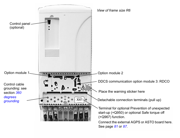
European CE compliant installation requires 360 ° high-frequency grounding to suppress electromagnetic interference.
Mechanical and Electrical Safety
Avoid single person operation during transportation, pay attention to the high temperature risk of the heat sink, and prevent conductive dust from entering the drive.
When handling printed circuit boards, it is necessary to wear a grounding wristband, and the bending radius of fiber optic cables should not be less than 35 mm.
Driver Overview and Compatibility
Product positioning
ACS800-04/U4 is an IP20 driver module suitable for industrial automation scenarios, supporting direct torque control (DTC) and compatible with permanent magnet synchronous motors.
Framework classification
Divided by power into R2 to R6 frames, different frames correspond to size, heat dissipation requirements, and installation methods (such as flange installation IP55).
Installation and Debugging
Mechanical Installation
Sufficient heat dissipation space needs to be reserved (such as 200mm space above the R2 frame), and the ventilation design of the cabinet needs to meet the air flow requirements.
During flange installation, IP55 protection must be ensured, and grounding must be connected independently.
electrical installation
Power connection: The input cable should match the rated voltage (208-690 V AC), use a symmetrical shielded cable, and ground the shielding layer 360 °.
Motor connection: Select cable specifications based on the frame (e.g. R2 frame motor cable ≤ 16 mm ²), avoiding the use of power factor compensation capacitors.
Control connection: Analog signals require twisted pair shielded cables, while digital inputs/outputs require attention to logic thresholds (12 V DC is “1”).
Installation of safety features
Prevent accidental startup (+Q950): An external AGPS board is required, powered by 230 V AC, and locked by a switch to prevent accidental startup.
Safe torque shutdown (+Q967): External ASTO board, 24 V DC power supply, in compliance with EN 61800-5-2 standard.
Technical parameters and performance
RATING
Current/power: For example, the R2 frame has a rated current of 5.1 A (230 V AC) and a continuous power of 1.1 kW; the R6 frame has a rated current of 290 A (690 V AC) and a continuous power of 200 kW.
Overload capacity: light load (10% overload) can last for 1 minute/5 minutes, heavy load (50% overload) can last for 1 minute/5 minutes.
Electrical characteristics
Input voltage fluctuation ± 10%, frequency 48-63 Hz, power factor 0.98 (rated load).
Output voltage 0 to input voltage, frequency 0-300 Hz, switching frequency 3 kHz (2 kHz for 690 V units).
Heat dissipation and derating
When the ambient temperature exceeds 40 ° C, the rated current will decrease by 1% for every 1 ° C increase; When the altitude exceeds 1000 meters, the rating will decrease by 1% every 100 meters.
Maintenance and component replacement
Routine maintenance
Clean the heat sink every 6-12 months and check the fan’s operating status annually (with a lifespan of approximately 6 years).
Capacitor replacement cycle: R4 and above frames take about 10 years and need to be reformed according to the manual.
component replacement
When replacing the fan, attention should be paid to model matching (such as the R2 frame fan requiring a flow rate of 35 m ³/h), and the functionality of the capacitor needs to be verified after replacement.
ABB UAD149A0011 3BHE014135R0011 is a powerful controller module that occupies an important position in industrial automation control systems. It is designed specifically for ABB’s AC 800M and AC 800PEC control systems, and can efficiently achieve key tasks such as data exchange, signal processing, and equipment control within the system. It is one of the core components for building a stable and intelligent industrial automation architecture.
Function characteristics
Communication function: As a communication module, it enables the AC 800M system to communicate smoothly with other devices on the Profibus network. Profibus is a widely used fieldbus standard in the industrial field. With excellent communication protocol conversion and data transmission capabilities, UAD149A0011 ensures fast and accurate data exchange between different devices, effectively improving the information flow efficiency of the entire industrial network.
Integrated I/O: This module integrates analog and digital I/O signal processing functions and can support multiple types of input and output signals. Whether it is analog signals from sensors such as temperature and pressure, or digital signals representing equipment status such as switch on/off and motor on/off status, they can be accurately collected and processed by it, and control signals can be output according to the system’s preset logic to achieve precise control of various industrial equipment.
High reliability diagnosis: Built in powerful self diagnostic function that can monitor its own working status in real time. By continuously monitoring hardware circuits, software programs, and data transmission processes, once a fault or abnormality is detected, the module will quickly issue an alarm and generate detailed diagnostic reports to help maintenance personnel quickly locate the problem, greatly reducing system downtime and ensuring the continuity and stability of industrial production.
Fast scanning and response: With fast scanning speed, it can complete the acquisition and processing of input signals in a very short time, and output control instructions in a timely manner. This feature significantly reduces the response delay of the system, enabling industrial automation systems to quickly respond to various changes in the production process, improving production efficiency and product quality.
Technical Parameter
Electrical parameters
Rated input voltage: 24VDC, suitable for common industrial DC power supply systems, ensuring stable power supply.
Isolation voltage: reaches a high standard, such as 2500Vrms, effectively isolates electrical interference between different circuits, ensuring the safety and reliability of the system.
Power consumption: Maintain at a reasonable level, with specific values depending on the actual workload. Lower power consumption helps reduce system operating costs.
Physical parameters
Size: Approximately 145mm x 145mm x 145mm, the compact design allows for flexible installation within limited control cabinet space, saving space resources.
Weight: Moderate weight facilitates installation and maintenance operations. Specific weight values can be found in the product manual.
I/O parameters
Analog input: Supports multiple types of analog input signals, such as 0-10V, 4-20mA, etc., with high resolution and accuracy, capable of accurately collecting analog data.
Analog output: It can output stable analog signals, which are used to control regulating valves, frequency converters and other equipment. The output accuracy is high and can meet the strict requirements of industrial control.
Digital input/output: With multiple digital input/output channels, it can quickly process digital signals, respond quickly, and is suitable for various switch control scenarios.
Application scenarios
Industrial automation production line: In automated production lines such as automobile manufacturing and electronic equipment production, UAD149A0011 can connect various sensors, actuators, and controllers to achieve comprehensive monitoring and precise control of the production process. For example, it can control the movement of the robotic arm based on the position information of the parts fed back by sensors, ensuring accurate grasping and assembly of the parts, and improving the automation level and production efficiency of the production line.
Process control system: In the field of process control in industries such as chemical, power, metallurgy, etc., this module can collect real-time process parameters such as temperature, pressure, flow rate, etc., and output control signals according to preset control strategies to adjust various equipment in the production process, such as valves, pumps, etc., to ensure stable operation of the production process, optimize production processes, improve product quality and production safety.
Intelligent building control system: In intelligent buildings, UAD149A0011 can be used to connect and control lighting systems, air conditioning systems, security systems, etc. By analyzing and processing various sensor data, intelligent adjustment of the building’s interior environment can be achieved, such as automatically adjusting lighting brightness based on indoor light intensity, automatically controlling air conditioning operation based on temperature changes, and improving the intelligence level and energy utilization efficiency of the building.
BSM N series: low inertia, high dynamic response, using neodymium iron boron magnets, peak torque can reach 4 times continuous torque, supports multiple feedback devices (rotary transformers, Hall sensors, incremental/absolute encoders), protection level IP54/55, working temperature -20 ℃ to+70 ℃, with IEC and NEMA configurations.
BSM C series: high inertia, economical and practical, peak torque is 3 times the continuous torque, suitable for applications that require higher inertia matching, and also supports multiple feedback devices and protection configurations.
SSBSM series: made entirely of stainless steel material, designed for food, liquid, sanitary, and corrosive environments, with a protection level of IP67, capable of withstanding 1500 psi flushing, and certified by BISSC, UL, cUL, and CE.
BSM 25&33 series: Durable circular shell design, supporting foot installation, using standard and reliable neodymium magnet design, can take advantage of brushless technology advantages such as low maintenance, quiet operation, fast acceleration, high torque and power output.
Technical Parameter
Electrical parameters: Different series of motors have different rated voltage, current, frequency and other parameters, such as BSM N series rated voltage 220V, rated current 15A, frequency 50/60Hz, isolation voltage 2500Vrms, etc.
Mechanical parameters: including motor size, weight, inertia, speed range, etc. For example, the BSM50N has dimensions of approximately 172mm × 95mm × 142mm, a weight of 2.4lbs/1.1kg, and a maximum rotational speed of 10000rpm.
Performance parameters: continuous stall torque, peak torque, torque constant, voltage constant, thermal resistance, thermal time constant, etc. For example, BSM50N-133 has a continuous stall torque of 3.9lb in (0.45Nm) and a peak torque of 15.9lb in (1.8Nm).
Performance Curve
The document provides current torque speed performance curves for different models of motors in various series, demonstrating the performance of the motors under different working conditions, helping users intuitively understand the operating status of the motors under various working conditions.
Dimensions and installation
IEC mounting: Detailed lists the installation dimensions of each series of motors, including parameters such as P, AB, U, AH, as well as the lengths of different models of motors with and without feedback devices, and the length and weight increase when equipped with brakes.
NEMA mounting: Introduces the relevant dimensional parameters of NEMA mounting, such as the dimensions of BSM50 series NEMA 23, BSM63/80 series NEMA 34/42, etc.
Options
Cooling kit: BSM90/100 and BSM132 series have blower cooling options, and different models of motors correspond to different blower kit numbers, voltages, currents, and air volumes.
Braking: Data on the holding torque, power, voltage, current, action time, and inertia of various series of motor brakes.
Connectors and cables: connector models, descriptions, and numbers for motor power, feedback, and other connections, such as MCSPOW-08, MCSRES-12, etc.
Engineering information
Motor identification matrix: BSM N, C series and BSM25, 33 series motor identification rules, including frame, series, size, winding code, options, etc.
Selection of servo motors: This article introduces the methods for calculating the requirements of servo motors, including determining the friction and inertia of the load, as well as calculating parameters such as speed, torque, inertia, etc. under different mechanical transmission modes (direct drive, gear drive, tangential drive, ball screw drive).
Motion Curve Analysis: How to interpret the speed time curve, calculate acceleration torque, operating torque, deceleration torque, and root mean square torque, and determine the torque demand of the motor throughout the entire working cycle.
Temperature calculation: Calculate the temperature rise of the motor winding based on power loss and thermal resistance, and determine whether the motor is operating within the safe temperature range.
Drivers and controllers
Servo drive: MicroFlex analog、MicroFlex e100、MicroFlex e150、MotiFlex e100、MotiFlex e180 The characteristics, parameters, models, and selection information of the series of drivers.
Motion controllers: The functions, number of axes, communication methods, and order codes of controllers such as NextMove ESB-2, NextMove e100, and NextMove PCI-2.
Software tool
ABB DriveSize and MCSize software tools can be used for the selection of servo motors and drives. MCSize has a motor database and selection criteria to help users easily and accurately choose suitable servo motors and drive systems.
PLC system
This article introduces the system overview, expansion capabilities, and features of the AC500, AC500 eCo, and AC500-XC series PLCs. For example, the AC500 CPU can locally expand up to 10 I/O modules, while the AC500-XC is suitable for extreme environments.
ALSTOM DFI-150-0003 Limelight Diagnostic Board is a high-performance flame detector circuit board designed specifically for industrial environments. Its core task is to accurately detect flames during welding, cutting, and various combustion processes, and to undertake the responsibility of safety monitoring. With advanced technology and reliable performance, it has become a key component in ensuring stable equipment operation and improving production efficiency in many industrial production processes.
Brand background
ALSTOM, as a leading global supplier of energy and transportation solutions, has an outstanding reputation in the industry. Over the years, with profound technological accumulation and a spirit of continuous innovation, ALSTOM’s products have widely penetrated into multiple important fields such as power, railway, and industry. Its strict control over quality and precise insight into customer needs make every product synonymous with reliability and advancement. The DFI-150-0003 Limelight diagnostic board is a typical representative of this brand philosophy.
Specification parameters
Electrical parameters
Rated voltage: 220V, suitable for common industrial power supply standards.
Rated current: 15A, meeting the current requirements for stable operation of the equipment.
Frequency: 50/60Hz, compatible with power frequencies in different regions.
Input voltage range: Supports DC working voltage and has certain voltage adaptability.
Isolation voltage: up to 2500Vrms, effectively ensuring circuit safety and preventing electrical faults from interfering.
Overvoltage protection: ± 30V, capable of handling instantaneous voltage fluctuations and protecting internal circuit components.
Static current: ≤ 5mA, with extremely low energy consumption in standby and other static states.
Dynamic current: ≤ 25mA, stable current during operation to ensure efficient operation of the equipment.
Physical and environmental parameters
Protection level: Available in IP66 or IP20 ratings. IP66 rating can achieve dust, water, and strong water spray prevention, suitable for extremely harsh industrial environments; The IP20 rating provides basic dust protection and is suitable for places with relatively good environments.
Working temperature range: -20 ℃ to+70 ℃, can work stably in cold or high temperature industrial scenarios.
Size: Typically 172mm x 95mm x 142mm, the compact design makes it easy to install inside various devices.
Interface and signal parameters
Output signal type: equipped with multiple switch output and analog output interfaces, convenient for connecting with different types of control systems. Simultaneously supporting RS485 communication ports to achieve efficient data transmission and communication.
Interface type: Provides digital or analog interfaces, which can be flexibly customized according to actual application needs to meet diverse device connection requirements.
Signal type: Supports infrared, ultraviolet, ion current, visible light, and multi band flame signal input, greatly improving the accuracy and comprehensiveness of flame detection.
Response time: less than 1 second, able to quickly capture changes in flame state and provide timely feedback information.
Core functions
Flame detection: Utilizing advanced sensor technology to accurately identify multiple flame signals. Both weak welding flames and high-temperature combustion flames can be quickly and accurately detected, providing reliable basis for subsequent control and decision-making.
Fault diagnosis: Built in powerful self diagnostic program, constantly monitoring its own working status. Once internal circuit faults or signal abnormalities are detected, clear alarm signals should be immediately issued to help maintenance personnel quickly locate the fault point and shorten equipment downtime.
Process control: Real time feedback of detected flame status information to the control system in the form of digital or analog signals. The control system adjusts the operating parameters of the equipment accordingly, such as adjusting the fuel supply of the burner, controlling the power of the cutting equipment, etc., in order to achieve precise control of the industrial production process, improve product quality and production efficiency.
Digital display: Equipped with an intuitive digital display screen, it presents real-time key parameters of the flame, such as flame intensity, combustion stability, etc. Operators do not need complex instrument detection, and can quickly understand the flame status through the display screen, which facilitates equipment debugging, maintenance, and daily monitoring.
Working principle
The DFI-150-0003 Limelight diagnostic board receives signals such as infrared, ultraviolet, ion current, and visible light generated by flames through specific sensors. After being preliminarily amplified by a preamplifier, these signals are transmitted to the signal processing circuit. The signal processing circuit uses complex algorithms to analyze, filter, and extract features from signals, in order to distinguish between real flame signals and environmental interference signals. Once the flame signal is confirmed to be valid, the diagnostic board will generate corresponding control signals and status information based on preset rules and algorithms. On the one hand, this information is transmitted to the external control system through the output interface for device operation control; On the other hand, it is visually presented on a digital display screen, making it convenient for operators to monitor in real-time. At the same time, the self diagnostic module will continuously check the hardware and software operation status of the diagnostic board itself to ensure the reliability of the entire system.
Key advantages
High sensitivity and anti-interference: Advanced signal processing technology and high-sensitivity sensors are used to accurately detect extremely weak flame signals. At the same time, through multiple filtering and anti-interference algorithms, the impact of environmental noise, electromagnetic interference and other factors on the detection results is effectively reduced, greatly reducing the false alarm rate and ensuring the accuracy and reliability of the detection results.
Quick response and alarm: When detecting flame abnormalities or equipment failures, it can respond in a very short time (less than 1 second) and quickly emit clear and loud alarm signals. This feature has won valuable time for timely handling of potential hazards and avoiding accidents, effectively ensuring the safety of industrial production.
Industrial grade design: From hardware material selection to software algorithms, strict industrial standards are followed for design. The high protection level shell, wide temperature range adaptability, and stable and reliable circuit design enable it to operate stably for a long time in harsh industrial environments such as high temperature, humidity, dust, and strong electromagnetic interference, with excellent durability and reliability.
Self diagnostic function: The powerful self diagnostic function can monitor the working status of the diagnostic board in real time, including the integrity of hardware circuits, the operation of software programs, etc. Once abnormalities are detected, maintenance personnel are immediately notified through the alarm system, greatly improving the convenience and efficiency of equipment maintenance and reducing equipment failure rates.
Digital reading function: The intuitive digital display screen presents the flame state and equipment operating parameters in a clear and easy to understand manner, allowing operators to quickly read information without complex training. This not only facilitates the daily operation and maintenance of the equipment, but also improves work efficiency and reduces operational errors caused by human error.
Precautions
Installation environment: It should be installed in a dry, well ventilated environment without strong electromagnetic interference. Avoid installing in high temperature, humid or dusty places to prevent affecting equipment performance and service life. If used in an environment with explosion-proof requirements, it is necessary to ensure that the equipment installation complies with the corresponding explosion-proof standards.
Electrical connection: When making electrical connections, it is necessary to strictly follow the requirements of the product manual. Ensure that the wiring is secure and avoid loose connections that may cause poor contact or short circuit faults. At the same time, attention should be paid to the matching of input and output voltage and current to prevent equipment damage due to mismatched electrical parameters.
Regular maintenance: It is recommended to regularly inspect and maintain the equipment, including cleaning the casing, checking for loose wiring, and testing the sensitivity of sensors. Regular maintenance helps to promptly identify potential issues and ensure that the equipment is always in optimal working condition.
Software upgrade: Follow the official software upgrade information released by ALSTOM and update the device’s software in a timely manner. Software upgrades typically fix known vulnerabilities, optimize performance, and enhance device stability and functionality.
Troubleshooting: When the device malfunctions and alarms, do not blindly disassemble or forcefully restart it. You should first refer to the fault diagnosis guide in the product manual to investigate the possible causes of the fault. If you are unable to resolve the issue on your own, please contact ALSTOM’s professional technical support personnel or authorized repair agencies in a timely manner.
ABB’s GCC960C102 motor driver is a high-performance drive device widely used in the industrial field, designed to provide precise and stable drive control for various types of motors. It can adapt to various types of motors, including AC asynchronous motors, synchronous motors, etc., and can meet the diverse needs of motor drive in different industrial scenarios. In industrial automation production lines, GCC960C102 can drive conveyor belt motors to ensure stable material transportation; In equipment such as fans and pumps, efficient driving of motors can also be achieved to optimize equipment operating efficiency.
Specification parameters
(1) Electrical parameters
Input voltage range: GCC960C102 can adapt to a wide range of input voltages and can operate stably between 380VAC and 690VAC. This wide voltage adaptability enables it to be used in industrial settings with different power environments, ensuring reliable operation in both modern factories with stable power supply and traditional industrial areas with certain voltage fluctuations.
Output current capability: Its maximum output current can reach [I1] A, which can meet the driving requirements of motors of various power levels. From small motors to medium and even some large motors, GCC960C102 can provide sufficient driving current to ensure the normal operation of the motor.
Frequency adjustment range: The output frequency adjustment range is 0Hz-600Hz. In practical applications, the output frequency can be flexibly adjusted according to the working requirements of the equipment driven by the motor, achieving a wide range of motor speed adjustment. For example, in some equipment that requires low-speed and high-precision operation of the motor, the output frequency can be precisely adjusted to a lower value; In devices that require high rotational speed, the frequency can be increased to a higher level.
Power factor: This driver has a high power factor, usually above 0.95. High power factor means that during the operation of the motor, the driver can more effectively utilize the power grid, reduce reactive power loss, lower the electricity cost of the enterprise, and also help improve the power supply quality of the grid.
(2) Mechanical parameters
Size: As mentioned earlier, its external dimensions are designed to be compact, measuring [L1] mm in length, [L2] mm in width, and [L3] mm in height. This size makes it easy to install inside equipment with limited space such as control cabinets and distribution boxes, effectively saving installation space for industrial equipment and optimizing system layout.
Weight: Approximately [W1] kg, which ensures the stability of the equipment and does not impose excessive burden on installation and handling. During the installation and maintenance of the equipment, staff can easily operate it, improving work efficiency.
Protection level: The protection level reaches IP [P1], which can effectively prevent dust from entering the interior of the drive, and also has the ability to protect against a certain degree of water splashing. This enables GCC960C102 to operate normally in complex industrial environments such as dusty and humid environments, such as textile workshops and food processing plants, greatly improving the product’s environmental adaptability and reliability.
(3) Communication parameters
Communication protocol support: Supports multiple common industrial communication protocols, such as Modbus RTU and Modbus TCP protocols. Through these communication protocols, GCC960C102 can communicate and connect with different brands and models of programmable logic controllers (PLCs), smart meters, upper computers, and other devices to achieve data exchange and collaborative control. In a typical industrial automation system, the driver can receive control instructions sent by the PLC through the Modbus protocol, such as commands for starting, stopping, and speed adjustment of the motor. At the same time, the operating status data of the motor, such as current, speed, fault information, etc., is fed back to the PLC, so that the operator can grasp the real-time operation of the equipment.
Interface type: Equipped with RS-485 interface and Ethernet interface. The RS-485 interface has strong anti-interference ability and a long transmission distance. In the complex electromagnetic environment of industrial sites, it can stably transmit data and can connect up to multiple node devices, achieving distributed control. The Ethernet interface provides high-speed data transmission capability, which can meet the communication needs of large data volumes and high real-time requirements. For example, in smart factories, a large amount of equipment status data needs to be quickly uploaded to the management system, and control instructions need to be issued to the drivers in a timely manner. Ethernet interfaces can meet these requirements well, ensuring the efficient operation of the system.
Core functions
Precise control of motor: Through advanced control algorithms and hardware circuits, GCC960C102 can achieve precise control of motor speed, torque, and steering. In terms of speed control, the speed accuracy can reach ± 0.1%, which can meet the extremely high requirements for speed accuracy in industrial applications, such as motor drive in precision machining equipment. In terms of torque control, the output torque can be adjusted in real time according to changes in motor load, and the torque control accuracy can reach ± 1%, ensuring that the motor can operate stably under different working conditions. At the same time, quick switching of motor direction can be achieved through simple control instructions to meet the requirements of different working modes of the equipment.
Rich protection functions: To ensure the safe operation of the motor and driver, GCC960C102 has multiple protection functions. The overcurrent protection function can quickly cut off the output current when the motor is overloaded or short circuited, preventing the motor and driver from being damaged due to excessive current. The overvoltage protection function can automatically take protective measures when the input voltage is too high, avoiding internal electronic components from burning out due to excessive voltage. The undervoltage protection function can stop the driver from working when the voltage is too low, preventing the motor from malfunctioning due to insufficient voltage, and also protecting the hardware of the driver. In addition, it also has an overheat protection function. When the internal temperature of the driver is too high, it will automatically reduce the output power or stop working to prevent component overheating and damage, and automatically resume operation after the temperature returns to normal.
Data monitoring and feedback: Equipped with powerful data monitoring functions, it can collect real-time operational data of motors, such as current, voltage, speed, temperature, etc. On the one hand, these data can be uploaded in real-time to the control system through a communication interface, providing operators with equipment operation status information and facilitating timely understanding of equipment working conditions; On the other hand, closed-loop feedback is used for motor control. For example, when the actual speed of the motor deviates from the preset speed, the driver automatically adjusts the output voltage or frequency based on the collected speed data to quickly restore the motor speed to the set value, ensuring the stability and accuracy of the motor operation. Through long-term monitoring and analysis of motor operation data, preventive maintenance of equipment can also be achieved, potential fault hazards can be detected in advance, equipment failure rates can be reduced, and production efficiency can be improved.
Flexible parameter settings: Users can flexibly set various parameters based on actual application needs through the driver’s operation panel or upper computer software. Basic parameters such as rated power, rated voltage, and rated current of the motor can be set, and advanced parameters such as control mode, acceleration and deceleration time, and torque compensation can also be adjusted. This flexible parameter setting function enables GCC960C102 to adapt to different types of motors and complex industrial application scenarios, meeting the diverse control needs of users. For example, in fan applications, appropriate acceleration and deceleration time and torque compensation parameters can be set according to the characteristic curve of the fan to achieve efficient and smooth operation of the fan; In the application of water pumps, the control mode can be adjusted according to the working requirements of the water pump to optimize its operational performance.
Key advantages
High reliability: ABB, as a globally renowned electrical equipment manufacturer, always adheres to strict quality standards in product development and production processes. The GCC960C102 motor driver uses high-quality electronic components and advanced manufacturing processes, and has undergone extensive simulation testing and practical verification to ensure stable and reliable operation in complex industrial environments. In harsh environments such as high temperature, high humidity, and strong electromagnetic interference, this drive can maintain normal operation with an extremely low failure rate, effectively reducing equipment downtime, ensuring production continuity, and reducing maintenance costs for the enterprise.
Excellent control performance: With advanced vector control algorithms and high-performance hardware platform, GCC960C102 achieves precise control of the motor. Its high precision in speed and torque control, fast dynamic response speed, can meet the strict requirements of various complex industrial applications for motor control. In fields such as precision machining and automated production lines, the excellent control performance of this driver can effectively improve product quality and production efficiency. For example, in electronic device manufacturing production lines, drivers can precisely control the movement of motors, ensuring accurate placement and welding of electronic components, and improving product yield.
Good compatibility: Supports multiple communication protocols and interface types, and can seamlessly integrate with devices of different brands and models. Whether it is ABB’s own automation products or other brands of PLC, sensors, actuators and other equipment, communication and collaborative work can be easily achieved. This good compatibility makes GCC960C102 have a wide range of application prospects in industrial automation systems. Whether it is the renovation and upgrading of old equipment or the construction of new automated production lines, it can be easily integrated into them, improving the flexibility and convenience of system integration.
Efficient and energy-saving: By optimizing the motor control strategy, GCC960C102 can dynamically adjust the output power according to the actual load situation of the motor, achieving energy-saving operation. Compared with traditional motor drive methods, using this driver can reduce motor energy consumption by 10% -30%. In the long-term operation process, it can save a lot of electricity costs for enterprises, which is in line with the concept of green industrial development. For example, in industrial fan and water pump applications, real-time adjustment of motor speed based on actual operating conditions avoids energy waste during constant speed operation of the motor, achieving significant energy-saving effects.
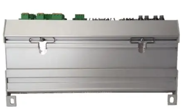
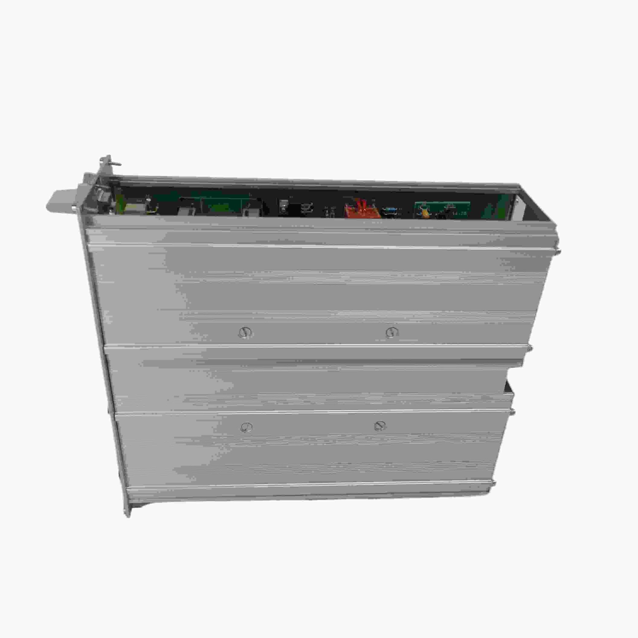
The UCU-22, UCU-23, and UCU-24 control units launched by ABB Industrial Drives are the core components in the field of industrial transmission control. These control units are mainly used to precisely regulate the operating status of various motors. On industrial automation production lines, they can accurately control the speed, direction, and torque output of motors based on preset programs and real-time feedback signals, thereby ensuring the stable and efficient operation of production equipment. From the perspective of appearance design, they adopt a compact structure.
Precautions
Installation environment requirements: It should be installed in a dry, well ventilated environment without severe vibration and electromagnetic interference. High temperature environment (over 50 ° C) may cause overheating of electronic components inside the control unit, affecting its performance and service life; High humidity environment (humidity greater than 85%) may cause electrical short circuit faults; Severe vibrations may cause internal components to loosen, resulting in poor contact and other issues; Strong electromagnetic interference may interfere with the transmission of control signals, leading to abnormal control. Therefore, it is necessary to choose a suitable installation location during installation, such as being away from strong electromagnetic interference sources such as large motors and transformers. If necessary, shielding measures can be taken.
Electrical connection specifications: When making electrical connections, it is necessary to strictly follow the product manual to ensure that the wiring is firm and correct. Incorrect wiring can lead to serious electrical faults such as short circuits and open circuits, damaging control units and motor equipment. At the same time, attention should be paid to the input and output voltage and current parameters of the control unit, and appropriate power sources and loads should be connected. It is strictly prohibited to operate beyond its rated parameters to prevent equipment damage from overvoltage and overcurrent.
Communication parameter settings: When communicating with other devices, it is necessary to correctly set communication protocol, baud rate, data bits, parity bits, and other parameters. The communication parameters between different devices should be matched with each other, otherwise it may cause communication failures and prevent data exchange and collaborative control. During the system debugging phase, it is necessary to carefully check the communication parameter settings to ensure stable and smooth communication.
Maintenance points: Regularly inspect and maintain the control unit, including checking whether the wiring is loose, whether there is dust accumulation on the module surface, and whether the cooling fan is running normally. Loose wiring may lead to increased contact resistance, affecting the stability of equipment operation; Excessive accumulation of dust may affect heat dissipation and cause equipment overheating; A faulty cooling fan may cause the control unit to overheat and damage internal components. If any abnormal situation is found, it should be dealt with in a timely manner, such as tightening the wiring, cleaning dust, replacing faulty fans, etc., to ensure the continuous and stable operation of the control unit.
Similar model supplement
ABB UCU-30 series: Compared with UCU-22, UCU-23, and UCU-24, the UCU-30 series has further expanded its functionality. It has added more communication interface options, in addition to the common RS-485 and Ethernet interfaces, it also supports CANopen protocol interfaces, which can meet some industrial application scenarios with special requirements for communication protocols. In terms of motor control performance, the UCU-30 series has higher control accuracy, with speed control accuracy up to ± 0.05% and torque control accuracy up to ± 0.5%. It is suitable for high-end manufacturing industries that have extremely strict requirements for motor control accuracy, such as semiconductor manufacturing equipment, precision medical equipment production equipment, etc.
ABB UCU-15 series: This series is positioned as an entry-level product and is relatively simplified in terms of functionality and performance compared to UCU-22 and others. It is mainly suitable for small industrial enterprises or simple automation equipment with low control function requirements and limited budget. The UCU-15 series only supports Modbus RTU communication protocol. In terms of motor control, the speed adjustment range is relatively narrow, from 0-2000 revolutions per minute, and the control accuracy is slightly lower, with a speed control accuracy of ± 0.5% and a torque control accuracy of ± 3%. But it has cost advantages, relatively low prices, and can meet the basic automation control needs of small businesses.
Operation principle and hardware
Hardware description
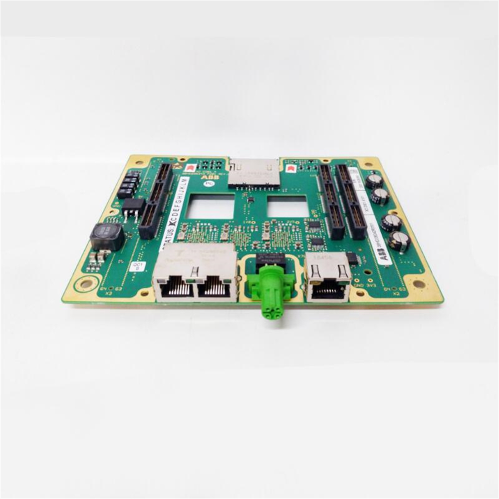
The control unit is an interface for external converter control signals, and it controls converter modules via fiber optic links. The control unit contains a control board and connector boards. The control unit contains integrated branching unit functionality for collecting and storing real-time data from the converter modules to help fault tracing and analysis. The data is stored on a memory card which can be analyzed by
ABBservice personnel.
The control unit requires an external 24 V DC power source. It has three option slots for I/O extensions, encoders and fieldbus adapters and functional safety modules,and aremovable memoryunit. If it is necessary to replace the control unit, you can keep the parameter settings by moving the memory unit from the defective control unit tothenewone.ThecontrolunithasoneoptionslotforconnectingaRDCODDCS communication option module. The control unit also has a connection for a control panel.
Thedrive-to-drive link (XD2D) is a daisy-chained RS-485 transmission line that allows basic master/follower communication with one master and multiple followers. The X485 connection provides a connection for the optional CIO-01 I/O module.
The control unit has two Ethernet ports for control network and two Ethernet ports fortool/gatewaynetwork.Environmentalsensorsonthecontrolunitmeasurehumidity and temperature
Mechanical installation
Examining the delivery
Makesurethat these items are included:
• controlunitwiththeI/Oconnector plugs
• memoryunit(UMU-01)
• microSDHCflashmemorycard(insertedinitsslot inside the memory unit)
• optionslotadapters(USCA-02)
• real-timeclock battery (BR2032).
Makesurethat there are no signs of damagetotheitems.
■ Identifying different control unit types
Before you install the control unit, make sure that it has the correct control program.
The control program is shown on the label attached to the memory unit.
Makesurethat the control unit is correct for your equipment configuration.
Additional information on the connections
■ Powersupplyforthecontrol unit (XPOW)
Refer to the control unit connector data for the current and voltage ratings of the power supply.
Connect an additional external power supply to the free +24 V and GND terminals of the XPOWterminal block if:
• thecontrolunitmustbekeptoperationalduringinputpowerbreaks,forexample,because of continuous fieldbus communication
• immediaterestartisnecessary after a power break (that is, no control unit power-up delay is permitted).
■ Digital interlock (DIIL)
Digital interlock input (DIIL) terminal is originally intended for interlock signals that stop the drive/unit when necessary. In the ACS880 primary control program, DIIL terminal is the source for the run enable signal by default. The inverter unit or drive cannot start, or it stops when there is no DIIL signal. In other control programs (and units), the default use of the DIIL terminal varies. Refer to firmware manual for more information.
Note: This input is not SIL or PL classified.
■ Control panel connection (XPAN)
The XPANconnectorcanbeusedtoconnectanassistant control panel or FDPI-02 diagnostics andpanelinterfaceunittothecontrolunit.WithFDPI-02,itispossibleto connectonecontrolpaneltotwoormorecontrolunitsinachaintopology,alsoknown asapanelbus.Formoreinformation,refertoFDPI-02diagnosticsandpanelinterface user’s manual (3AUA0000113618 [English]).
The XPANTERMswitchsetsthetermination for the panel bus. Must be set to ONif thereisnopanelbus,orifthecontrolunitisthelastoneinapanelbus.Onintermediate units in a panel bus, set termination to OFF (1).
■ TheXD2Dconnector
The XD2DconnectorhasanRS-485connection that can be usedfor
• basicmaster/follower communication with one master drive/unit and multiple followers
• fieldbuscontrol through the embeddedfieldbus interface (EFB)
• drive-to-drive (D2D) communication implemented by application programming.
Refer to the firmware manual for the availability of these features and related parameter settings.
Terminate the bus on the units at the ends of the drive-to-drive link. Disable bus termination on the intermediate units.
Useashieldedtwisted-paircablefordata,andanotherpairorawireforsignalground(nominalimpedance100 165ohm,forexampleBelden9842).Forthebestimmunity use high quality cable. Keep the cable as short as possible. Avoid unnecessary loops and parallel runs near power cables such as motor cables.
ABB XDD501A101 bus terminal module, product number XDD501A101, corresponding to 3BHE036342R0101, originated in Sweden, is a key component for equipment connection and signal transmission in the field of industrial automation. Its design is compact, although there is currently no official exact size, it can be inferred from similar products that it can adapt to the limited space of various control cabinets and distribution boxes, which is conducive to system integration layout. Weighing approximately 2kg, it balances the stability of internal components with stable performance, making it easy to handle, install, and maintain.
Brand background
ABB Group is a globally renowned leader in the fields of power and automation technology, with operations in over 100 countries and 132000 employees. In 1988, it was formed by the merger of ASEA from Sweden and BBC from Switzerland, with its headquarters located in Zurich, Switzerland. ABB has a deep foundation in the field of electrical equipment manufacturing, having developed numerous major technologies such as the world’s first three-phase transmission system, high-voltage direct current transmission technology, and the first electric industrial robot, and being the first to achieve commercial applications. Occupying a dominant position in the field of high-voltage direct current transmission systems, it is one of the four giants of global industrial robots. Its sales volume, installation volume, and transportation volume of power grid equipment rank first in the world. In the process automation market of the process industry, it has long held the top spot with its powerful DCS control system.
Specification parameters
Working voltage: It usually supports a wide voltage range, such as 24VDC to 48VDC, which can adapt to power configurations in different industrial scenarios and ensure stable operation in various power environments.
Weight: Approximately 2kg, convenient for staff to carry out transportation operations during installation, commissioning, and maintenance.
Communication Protocol: It is highly likely to support common industrial communication protocols such as Modbus to achieve efficient communication connections with PLCs, smart meters, upper computers, and other devices of different brands and models, and to build a massive industrial control network.
Interface type: Equipped with standard electrical interfaces, such as RS-485 interface, utilizing its excellent anti-interference ability and long transmission distance to stably transmit data in complex electromagnetic environments of industrial sites, and can connect up to multiple node devices; It may also have Ethernet interfaces to achieve high-speed data transmission, meeting communication scenarios with high data volume and real-time requirements.
Core functions
Signal transmission: Efficiently and accurately transmit analog signals (such as continuously changing voltage signals from temperature sensors and current signals from pressure sensors) and digital signals (such as on/off status signals of switches and start/stop signals of motors) generated by on-site equipment to the control system. At the same time, the control instructions of the control system are transmitted in reverse to on-site executing devices (such as motors and valves) to ensure bidirectional data exchange and coordinated operation of the entire industrial automation system. For example, on an automated production line, sensors transmit information such as product location and quantity to the PLC control system through this module. After processing, the PLC sends control signals to the motor through this module to adjust the running speed and start stop of the conveyor belt.
Device Connection: As a bridge connecting on-site devices and control systems, it can connect various types of sensors, actuators, and other devices to achieve interconnectivity between different devices, integrating various dispersed devices into an organic automation control system. In smart buildings, sensors and controllers of lighting systems, air conditioning systems, security systems, and other equipment can be connected and centrally managed and intelligently regulated through a central control system.
Working principle
When the on-site equipment generates a signal, whether it is analog or digital, the XDD501A101 bus terminal module will first collect the signal. For analog signals, they may be converted into digital signals through internal analog-to-digital conversion circuits for subsequent processing and transmission. Next, the module packages the processed signals into specific format data packets based on the supported communication protocol (such as Modbus), and sends them to the control system through the corresponding interface (such as RS-485 or Ethernet interface). When the control system issues a control command, the module receives the command data packet, parses the control information, and converts it into a signal form suitable for on-site execution equipment (such as analog output signal controlling valve opening, digital output signal controlling motor start stop), thereby driving the execution equipment to complete the entire control process.
Key advantages
High reliability: Using high-quality electronic components and advanced manufacturing processes, it has good electrical insulation performance and anti-interference ability. It can operate stably in complex industrial environments (such as strong electromagnetic interference, high humidity, and high dust), reduce equipment failure rates, and ensure the reliable operation of the system.
Flexible compatibility: Supports multiple communication protocols and interface types, seamlessly connects and communicates with devices of different brands and models, adapts to diverse industrial automation system architectures, greatly improving the flexibility and convenience of system integration.
Compact design: With its compact size and light weight, it is not only easy to install in equipment such as control cabinets with limited space, but also reduces transportation and installation costs, improving system deployment efficiency.
Powerful signal processing capability: capable of quickly and accurately collecting and transmitting various signals, meeting the real-time and accuracy requirements of industrial automation systems, ensuring the timeliness and accuracy of system control.
Precautions
Installation environment: It should be installed in a dry, well ventilated environment without severe vibration and electromagnetic interference, avoiding installation in high temperature, high humidity or dusty places to ensure the normal operation and service life of the module.
Electrical connection: When making electrical connections, it is important to ensure that the wiring is firm and correct to avoid short circuits, open circuits, and other situations. At the same time, it is necessary to strictly connect the appropriate power supply and load according to the electrical parameter requirements of the module to prevent overvoltage and overcurrent damage to the module.
Communication settings: When communicating with other devices, it is necessary to correctly set communication protocol, baud rate, data bits, parity bits, and other parameters to ensure stable and smooth communication. The communication parameters between different devices should match each other, otherwise it may cause communication failures.
Maintenance: Regularly inspect and maintain the module, such as checking for loose wiring and dust accumulation on the module surface. If any abnormal situation is found, it should be dealt with in a timely manner to ensure the continuous and stable operation of the module.
Similar model supplement
ABB XDD502A101: Similar in functionality to XDD501A101, but with an increased number of ports, it may be suitable for complex system scenarios that require connecting more devices, further improving system integration.
ABB XDD501B101: Optimized in terms of communication performance, supporting higher communication rates and better adaptability for industrial automation applications that require extremely high data transmission speeds, such as data acquisition and control for high-speed production lines.
Product positioning: S800 I/O DTM 5.3 is a device type manager software component launched by ABB for S800 I/O modules, which complies with the FDT 1.2 specification and can be used in conjunction with framework applications that comply with this specification.
Support modules: covering various S800 I/O modules, including communication interface modules (such as CI801, CI840), analog input/output modules (such as AI801, AO801), digital input/output modules (such as DI801, DO801), and pulse counter modules (such as DP820, DP840).
Version and Release Information: The document version is 3BSE027630-510 A, released in February 2013, suitable for S800 I/O DTM 5.3 version, supporting 64 bit operating systems and 800xA 5.1 Feature Pack 3 scenarios.
Function characteristics
Core functions
Equipment configuration and diagnosis: Provide a graphical configuration interface for various types of S800 I/O modules, which can set parameters such as signal range, filtering time, redundancy mode, etc; Equipped with comprehensive diagnostic functions, it can display module status, channel errors, and diagnostic information related to HART devices.
Data collection and processing: It can collect analog and digital data in real time, process, display, and store them, and support dynamic data viewing and monitoring.
Communication and Interface: Supports multiple communication protocols (such as Modbus) and interfaces (Ethernet, serial port, CAN bus, etc.) to achieve data exchange with other devices and systems; Some modules support the HART protocol and can communicate with HART instruments.
Redundancy and security mechanism: Some modules support redundant configuration (such as CI840, AI845, etc.) to improve system reliability; Equipped with fault diagnosis and monitoring functions, it can monitor equipment status in real-time and issue alarms.
Featured Features
HART tool routing: supports HART DTM connection, enables configuration and monitoring of HART instruments, and can perform HART parameter settings, device scanning, and other operations.
Event Sequence (SOE): Some digital input modules (such as DI825, DI830, etc.) support SOE functionality and can record timestamps of digital input signals for fault analysis and event tracing.
Dynamic data monitoring: Provides real-time display of dynamic data from various modules, such as analog values, digital status, pulse counting, etc., supporting periodic reading and single update.
Installation and system requirements
System prerequisites
Operating system: Supports Windows Server 2008 (32/64 bit), Windows 7 (32/64 bit), etc.
Software dependencies: ABB FDT Shared Components 13.0.0.0 and ABB FDT Base Container 13.0.0.0 need to be installed. Remote I/O requires PROFIBUS master DTM, and HART functionality requires HART DTM (such as Basic HART DTM).
Installation process
Insert the installation CD, run Setup. exe, and follow the wizard to select the installation components.
You can choose to install locally or copy to the server, and support generating installation logs.
Maintenance and uninstallation: Maintenance operations can be performed through the control panel, including changing components, repairing programs, or uninstalling; During uninstallation, it is necessary to confirm and wait for the process to complete.
Operation and Handling
User Interface and Roles
Interface composition: including title bar, toolbar, application area, status bar, etc. Different applications (such as diagnosis, configuration, observation, etc.) have corresponding interface layouts.
User roles: divided into operators, maintenance personnel, planning engineers, etc., different roles have different access permissions to various application functions (such as read/write permissions).
Main application functions
About DTM: Display DTM version, release information, etc.
Identification: Display module hardware information, such as type, manufacturer, location, version, etc.
Diagnosis: Display module and channel diagnostic status, including error types, warning messages, etc.
Observe: Real time monitoring module for dynamic data, such as analog values and digital status, supporting periodic refreshing.
Configuration: Set module parameters such as signal range, filtering time, redundancy mode, OSP value, etc.
Parameterization: Set HART parameters for the HART module, such as retry count, scan status, etc.
Service: Execute special function commands, such as resetting modules, reading diagnostic history, switching redundant modules, etc.
Dynamic data: Each module defines pre dynamic data connections, such as station warnings and redundant power failure signals for CI801, analog values and channel states for AI801, digital values for DI801, etc. The data types include bytes, integers, Boolean values, etc.
Application area
Industrial automation: suitable for production line automation control, data acquisition and processing, equipment status monitoring and maintenance, etc. It can control equipment such as motors, valves, sensors, etc.
Railway transportation: used for train tracking and signal management, safety mechanism control, onboard system diagnosis and communication, etc., such as implementing PROFIBUS communication through CI801/CI840 modules.
Energy management: Monitoring and controlling equipment and systems involved in energy production, transmission, and distribution processes in industries such as electricity, oil, and natural gas.
Intelligent building: Centralize control and management of mechanical and electrical equipment (such as elevators, air conditioning, lighting systems) within the building to achieve intelligent operation and energy conservation.
Precautions and limitations
Compatibility: S800 I/O DTM 1.0/0 and higher versions do not support FDT 0.98 specification framework applications; Some module functionalities (such as SOE) are only supported in specific framework applications (such as AC870P/Composer).
Security and Permissions: Operations involve security measures (such as user access, password security, etc.), and users are required to conduct risk assessments and be responsible for the correct configuration, installation, and maintenance of related equipment and software.
HART function limitation: When the HART instrument is connected to modules such as AI895/AO895 during operation, it needs to manually perform “Perform master reset” to be detected; When the HART communication main module fails, manual switching is required.
This module has excellent data collection capabilities and can quickly and accurately receive data from various sensors and other external devices. Both analog data such as temperature, pressure, and flow rate, as well as digital data such as position and switch status, can be efficiently collected. Moreover, it integrates high-performance processors internally, which can perform real-time analysis, calculation, and processing of collected data, providing accurate basis for subsequent control decisions. For example, on industrial production lines, real-time collection of equipment operating parameters can be used to determine whether the equipment is operating normally after processing.
Control signal output
It can generate and output diverse control signals for precise control and regulation of various actuators and systems in trains, vehicles, and industrial equipment, such as motors, valves, cylinders, etc. Through precise signal output, precise control of equipment motion speed, position, torque and other parameters is achieved to ensure stable operation of the equipment according to preset process requirements. In the automated production process, it is possible to accurately control the motor speed to adjust the material conveying speed or control the valve opening to adjust the liquid flow rate according to the production process requirements.
Rich communication interfaces
Equipped with various types of communication interfaces, such as Ethernet interface, serial port (RS-232/RS-485), CAN bus interface, etc. These interfaces enable the module to conveniently interact and communicate with other devices and systems, building a large and efficient industrial control network. With the help of Ethernet interfaces, high-speed data transmission can be quickly achieved with devices such as upper computers and PLCs, enabling remote monitoring and control; Through the CAN bus interface, stable communication and collaborative work can be achieved with other node devices on the bus.
Programmable and flexible configuration
With the characteristics of programmability and flexible configuration, users can set parameters, define functions, and write control logic for modules through professional programming software according to specific application scenarios and needs. Both simple sequential control and complex logical operations and closed-loop control can be easily implemented. This flexibility enables the module to be widely applied in projects with different industries and process requirements, greatly improving its versatility and applicability.
Fault diagnosis and monitoring
Built in comprehensive fault diagnosis and monitoring functions, capable of real-time monitoring of its own working status and the operation of connected devices. Once an abnormality is detected, such as communication failure, data error, equipment overload, etc., an alarm can be quickly issued and the fault information can be fed back to the upper computer or operator through the communication interface. At the same time, the module will automatically record detailed information such as the time and type of the fault occurrence, which facilitates subsequent troubleshooting and analysis, effectively ensuring the reliability and safety of the system, and reducing equipment downtime and maintenance costs.
Performance parameters
Electrical parameters
Input voltage: The working voltage range is relatively wide, usually between 24V and 110V, which can adapt to the application needs of different power environments. Whether it is low-voltage small equipment or high-voltage large industrial systems, they can be stably connected and work.
Output voltage: It can provide a stable 5VDC output voltage to provide reliable power supply for connected load devices, ensuring that the equipment operates normally at a stable voltage.
Input current: The maximum input current can reach 2A, which can meet the access requirements of some sensors or external devices with high current requirements, ensuring the stability of data acquisition and communication.
Processor speed: The equipped processor runs at a speed of up to 26MHz and has powerful data processing capabilities. It can quickly respond to various control instructions, efficiently process collected data, and achieve real-time and precise control of the device.
Memory capacity: Equipped with 128-256MB DDR memory, it provides sufficient space for data storage, program execution, and intermediate data processing, ensuring that the module can run smoothly under complex work tasks without experiencing lag or data loss due to insufficient memory.
communication parameters
Communication protocol support: Supports multiple common and widely used communication protocols, such as Modbus TCP/IP, Modbus RTU, DNP3, etc. This enables the module to seamlessly communicate with devices of different brands and types, making it easy to integrate into various industrial automation systems. For example, through the Modbus protocol, it is easy to exchange data and collaborate with devices such as PLCs and smart meters that support this protocol.
Interface type: Equipped with standard electrical interfaces, such as Ethernet interfaces, it can achieve high-speed and long-distance data transmission, with transmission rates up to 10/100Mbps or even higher, meeting communication scenarios with high data volume and real-time requirements; The RS-232 interface is suitable for short distance, low-speed data communication and is commonly used to connect debugging equipment, simple sensors, etc; The RS-485 interface has stronger anti-interference ability and longer transmission distance, which can stably transmit data in the complex electromagnetic environment of industrial sites, and can connect up to multiple node devices. The CAN bus interface plays an important role in industrial control networks due to its high-speed, reliable, and multi master communication characteristics, and is suitable for connecting devices that require extremely high real-time and reliability.
Environmental adaptability parameters
Working temperature range: It can work stably in harsh temperature environments, with a working temperature range from -20 ° C to+60 ° C. This allows the module to operate normally in cold northern winter outdoor equipment and hot southern summer high-temperature workshops without the need for additional temperature control equipment, greatly improving its applicability in different regions and working environments.
Storage temperature range: Even in non working conditions, the module can adapt to a wider range of temperature storage conditions, with a storage temperature range of -55 ° C to+125 ° C. This ensures that the module will not be damaged due to changes in environmental temperature during transportation, inventory, and other processes, extending its service life and reliability.
Humidity adaptability: It also has good adaptability to humid environments and can work normally in environments with relative humidity of 5% to 95% and no condensation phenomenon. Whether in humid coastal areas or production workshops in industries such as chemical and textile with high humidity, modules can perform tasks stably, ensuring the continuous operation of the system and preventing faults such as short circuits and corrosion caused by humidity issues.
Dimensions and physical characteristics
Size: The module adopts a compact design with external dimensions of 20cm x 20cm x 20cm. This small volume allows it to be easily integrated into various space limited control panels, control cabinets, or vehicle systems, without occupying too much installation space, facilitating system layout and design.
Weight: The weight is about 10kg, which ensures the stability of the electronic components and structure inside the module, and is not too heavy. It is easy to install, disassemble, and maintain, reducing the difficulty and labor intensity of manual operation.
Protective design: The shell is made of sturdy and durable materials, with a certain level of protection, which can effectively prevent dust and foreign objects from entering, and also provide good mechanical protection for internal electronic components. In complex industrial environments such as mines and cement plants with large amounts of dust, it is possible to ensure the normal operation of modules and reduce the occurrence of failures caused by external factors.
Application Fields
Railway transportation field
Train tracking and signal management: In the railway network, accurate tracking of trains and intelligent management of signals are achieved by collecting real-time information such as train position and speed, and communicating with the signal system. Ensure safe operating intervals between trains, control the display of signal lights reasonably, and guarantee the efficiency and safety of railway transportation.
Security mechanism control: Integrate automatic train protection (ATP) and other safety functions to monitor and control the real-time operation status of the train. Once abnormal situations are detected, such as overspeed or signal intrusion, corresponding safety braking measures will be immediately triggered to ensure the safe operation of the train and prevent accidents from occurring.
On board system diagnosis and communication: responsible for data collection, processing, and communication of the train’s onboard system, transmitting various operating parameters of the train, such as vehicle status, equipment failure information, etc., to the central control system in real time, facilitating staff to timely understand the train’s operating conditions, conduct remote diagnosis and maintenance, and improve the availability and reliability of the train.
Industrial automation field
Production line automation control: It can be used to control the start stop, speed adjustment, material handling system operation, and robot arm movements of various industrial production lines. By precise control signal output, the automation and intelligence of the production process can be achieved, improving production efficiency, reducing labor costs, and enhancing the consistency and stability of product quality.
Data Collection and Processing Center: As the core module of data collection and processing in industrial automation systems, it collects sensor data from various links on the production line, such as temperature, pressure, flow rate, position, etc., and performs real-time analysis and processing. Based on the processing results, optimize and adjust the production process to achieve refined control, improve resource utilization and production efficiency.
Equipment status monitoring and maintenance: Utilize its fault diagnosis and monitoring functions to monitor the operating status of production equipment in real time and predict possible equipment failures. Through early warning, staff can arrange maintenance plans in a timely manner, carry out preventive maintenance, avoid production interruptions caused by sudden equipment failures, reduce equipment maintenance costs, and extend equipment service life.
Other areas
Energy management system: used in energy industries such as electricity, oil, and natural gas to monitor and control various equipment and systems involved in energy production, transmission, and distribution processes. For example, in power plants, it is possible to control the start stop and load regulation of generator units, as well as monitor and adjust the power parameters of the grid to ensure stable and efficient energy supply.
Intelligent building control system: In large commercial buildings, office buildings and other intelligent buildings, it is responsible for centralized control and management of various mechanical and electrical equipment inside the building, such as elevators, air conditioning, lighting systems, etc. By collecting and analyzing data, intelligent operation of equipment can be achieved, achieving the goals of energy conservation, comfort, and convenience, and improving the management level and user experience of buildings.
Communication protocol support: Supports multiple common communication protocols, such as Modbus protocol, for data exchange and collaborative work with other devices. Through the Modbus protocol, it is easy to connect with devices such as PLCs and upper computers, receive control commands, and provide feedback on the working status of modules, achieving centralized control and monitoring of the entire automation system.
Interface type: Equipped with standard electrical interfaces, such as [interface type, such as RS-485 interface, etc.]. These interfaces have good universality and compatibility, making it easy to connect with various external devices. For example, the RS-485 interface can achieve long-distance data transmission, has strong anti-interference ability, and can meet the data communication needs in complex industrial environments.
Functional Features
Precise pulse control: capable of generating high-precision pulse signals at a predetermined frequency and number of pulses, and can accurately control the start, stop, speed, and position of external devices. For example, in positioning mode, mechanical components can be accurately moved to preset positions.
Multiple working modes: According to different application scenarios, it has multiple working modes, such as positioning mode, speed mode, and torque control mode. In speed mode, the speed of the actuator is determined by controlling the pulse frequency; In torque control mode, the motor current is controlled by pulse signals to control the output torque.
Signal isolation and amplification: To ensure the stability and reliability of the signal, it usually has signal isolation function, which can prevent external interference from affecting the system, and amplify the pulse signal to meet the driving requirements of different loads.
High reliability design: Using high-quality electronic components and advanced manufacturing processes, it has strong anti-interference ability and stability, and can operate stably for a long time in harsh industrial environments, ensuring the reliable operation of the system.
Application area
Industrial automation: In production lines, it can be used to control the movement of robotic arms, the start stop and positioning of conveyor belts, etc., achieving automation and precise control of the production process. For example, in the automobile manufacturing production line, controlling the robotic arm to perform component assembly work.
Numerical Control Machine Tool: Used to control the precise positioning and movement of machine tool tools, achieve high-precision machining of workpieces, and improve machining quality and efficiency. On a CNC milling machine, the path of the tool is precisely controlled through a pulse output module to process
Complex shaped parts.
Robot control: It can accurately control the joint movements of robots, achieve precise movements such as positioning, grasping, and operation, and is widely used in industrial robots, service robots, and other fields.
Packaging Machinery: Used in packaging production lines to control precise measurement, filling, and packaging operations of materials, such as precise cutting of continuous feed, accurate counting and positioning of packaged items, etc., to improve packaging efficiency and quality.
Working principle: This module is usually used in conjunction with control systems such as programmable logic controllers (PLCs). The PLC sends instructions to the ALSTOM N897164610L pulse output module according to the preset program and logic. After receiving the instructions, the module generates pulse signals of corresponding frequency, pulse number, and duty cycle according to the instructions. These pulse signals are transmitted to external devices such as stepper motors, servo motors, etc., to control the movement and operation of the equipment.