Call us 24/7uaedcs@163.com
Welcome to the official website of CNIACS Automation Technology Co., Ltd!
Call us 24/7uaedcs@163.com

ABB INSUMMCU2 MCU2A02V24 motor control unit

Product overview

Product positioning: MCU is an electronic motor control and protection device with fieldbus interface, mainly used for the protection, control, and monitoring of three-phase/single-phase AC motors and starting equipment. It is divided into MCU1 (basic type) and MCU2 (high-end type).

Mechanical structure: It consists of a base plate, a main unit, a current measurement unit, and a voltage unit (optional only for MCU2). The outer shell is made of polycarbonate containing 10% glass fiber, with a fire rating of UL 94 V-0, halogen-free, and a color of RAL 7012.

Model specifications: MCU2 has two current ranges of 0.1-3.2A and 2.0-63A, supporting 380-690VAC voltage and 24VDC/230VAC auxiliary power supply.

Interface function

Power interface: Supports 24VDC (MCU1 and MCU2) and 230VAC (MCU2 only) auxiliary power supplies, with power consumption of 4.7W and 8.2W (maximum), respectively.

Digital input: MCU1 has 12 channels, MCU2 has 17 channels, with a type of 10mA/24VDC, and can be configured as normally open or normally closed.

LED output: 9 channels, used to indicate motor operation status, alarms, and trips, requiring external current limiting resistors.

Contactor control output: MCU1 has 2 channels and MCU2 has 3 channels, equipped with a watchdog relay to prevent abnormal operation of the contactor in case of microprocessor failure.

Communication interface: LonTalk is used ®  Protocol, FTT-10A transceiver, supporting LONWorks fieldbus, can achieve parameter configuration and status monitoring through network variables.

Function characteristics

Starter type: Supports multiple starter types, including NR-DOL (unidirectional direct start), REV-DOL (bidirectional direct start), NR-S/D (star delta start), REV-2N (dual speed non reverse), etc. Each type corresponds to different contactor control logic and parameter settings.

Protection function:

Thermal Overload Protection (TOL): Simulate motor thermal capacity, calculate thermal accumulation based on current, and support both standard and EEx e models.

Phase loss protection: detects phase current imbalance to prevent motor phase loss operation.

Underload/no-load protection: detects motor load abnormalities based on current and power factor.

Locked rotor protection: monitors the overcurrent status during motor start-up or operation.

Ground fault protection: Detecting ground faults through residual current transformers or phase current vector sum.

Monitoring and Diagnosis:

Contactor watchdog: monitors the status of the contactor and cuts off the control voltage in case of abnormalities.

Feedback supervision: Verify the consistency between the contactor action and the control command.

Running time counting: records the number of motor running hours and the number of contactor actions, used for maintenance reminders.

Fault record: stores alarm and event information, with timestamps, supports network queries.

Communications and Networking

Protocol and Interface: Using LONWorks fieldbus, supporting SNVT (Standard Network Variable Type), it can communicate with other devices in the INSUM system (such as MMI, gateway).

Network configuration: Supports service/flashing installation mode, achieves device recognition and network connection establishment through testing location input.

Time synchronization: Receive system clock synchronization messages to ensure the accuracy of event timestamps.

​Parameter setting and maintenance

Parameterization process: To download parameters through INSUM Operator Station or MMI, the MCU needs to be set to offline mode and support partial or complete parameter file transfer.

Fault code: Display a fault code when parameter settings are incorrect, indicating specific parameter issues (such as out of range, invalid values, etc.).

Technical data: Operating temperature -5 ℃ to+55 ℃, storage temperature -25 ℃ to+85 ℃, protection level IP20, compliant with IEC 60947 and other standards, passed EMC compatibility testing.

ABB INSUM ®  Advantages of MCU

Strong communication and integration capabilities: Supports LONWorks fieldbus, can communicate with multiple devices, and achieve system integration. If combined with other ABB devices such as MMI and gateway, it can build an efficient motor management network in complex industrial environments. In the automated production lines of large factories, seamless integration with the upper control system enables centralized monitoring and management of a large number of motors, which is difficult for many other brands to achieve. In contrast, some other brands of motor control units support fewer types of communication protocols, making it difficult to integrate with devices from different manufacturers, which limits the scalability and compatibility of the system.

Comprehensive and precise protection functions: equipped with multiple protection functions such as thermal overload, phase loss, underload/no-load, locked rotor, grounding fault, etc. Its thermal overload protection simulates the motor’s thermal capacity and can accurately monitor the motor’s operating status, effectively avoiding damage to the motor due to abnormal working conditions. Taking the manufacturing industry as an example, in the application scenario of frequent starting and stopping of motors, timely response and protection of motors can be achieved, reducing equipment failure rates and ensuring production continuity. The protection functions of some other brands may not be complete enough, or there may be a lack of protection accuracy, which cannot be compared to ABB INSUM ®  MCU provides comprehensive and precise protection for motors.

High product stability: The hardware design adopts a polycarbonate shell containing 10% glass fiber, with a fire rating of UL 94 V-0, halogen-free, and good mechanical stability and electrical insulation performance. The working temperature range is -5 ℃ to+55 ℃, which can adapt to various industrial environments. In some high temperature, high humidity, or corrosive industrial environments, ABB INSUM ®  MCU can operate stably, while some other brands of motor control units may not be able to adapt to such harsh environments, resulting in decreased stability and affecting the normal operation of the motor.

Rich product selection: ABB offers different models such as MCU1 and MCU2, suitable for different motor powers and application scenarios. MCU2 has two current ranges to choose from, 0.1-3.2A and 2.0-63A, to meet diverse motor control needs. In contrast, some other brands’ product lines may not be rich enough to meet the specific needs of different users.

Abb Electric Vehicle Motor Controller - Jean Meridith

ABB REF 542plus multifunctional protection

Product Core Value

REF 542plus, as an intelligent electronic device for medium voltage distribution systems, integrates protection, measurement, control, monitoring, and power quality analysis functions. The configuration tool enables device parameter customization, functional logic design, and system integration through a graphical interface and programmable logic, ensuring safe and efficient operation of equipment in scenarios such as substations and industrial automation.

Installation Guide for Configuration Tools

2.1 System Hardware Requirements

Processor: Intel Pentium series and above

Memory: At least 128MB RAM (recommended 256MB or more)

Storage: 50MB of available hard disk space (recommended to reserve over 100MB)

Peripherals: CD-ROM/VD-ROM drive, mouse

Interface: At least 1 RS-232 serial port (for serial connection), 1 Ethernet interface (for TCP/IP connection)

2.2 Software Environment Requirements

Operating systems: Windows NT 4.0 SP6, Windows 2000, Windows XP, Windows Vista

Supporting components: NET Framework 2.0 and above (some features depend on)

Language support: English, German, Italian, Czech, Slovak (default English)

ABB 馈线终端 REF541 数字继电器 - 启明自动化

2.3 Detailed explanation of installation process

Start the installation program: Insert the installation media, run setup. exe, and automatically detect the system language (such as English, German, etc.).

Select installation type:

Full installation: Includes all components (configuration tools, sample files, help documentation), occupying approximately 80MB of space.

Custom installation: Optional installation of components (such as installing only core tools or language packs).

Configuration options:

Select the installation path (default C: \ Program Files \ ABB \ REF 542plus).

Check the required language pack (such as English, German).

Optional installation of sample project files (for easy learning and use).

Installation completed: The program automatically creates desktop shortcuts and start menu folders, and some systems require a restart to take effect.

2.4 Unloading and Troubleshooting

Uninstalling steps: Use Control Panel → Add/Remove Programs → REF 542plus Configuration Tool to uninstall.

Common problems:

Installation failed: Check disk space and compatibility with the operating system, close antivirus software and try again.

Start error: Confirm NET Framework components are complete, reinstall the runtime environment.

Core operating interface of configuration tool

3.1 Main interface layout

Menu bar: Includes seven menus: File, Connect, View, Configure, Utilities, Options, and Help.

Toolbar: Shortcut buttons include New, Open, Save, Connect Device, Download Configuration, etc.

Project workspace: Display the current project structure, including hardware configuration, FUPLA diagrams, HMI settings, etc.

Status bar: displays information such as connection status, current operation progress, error prompts, etc.

3.2 Project Management Process

New Project:

Click on File ->New to automatically generate the new.ref project file.

Fill in project information (project name, feeder name, customer information, etc.).

Open project:

Support opening. ref format project files, allowing browsing of historical project records (last 4).

ABB PP886 Compact Product Suite hardware selector

Product positioning and functional overview

Product positioning: PP886 is a standard touch screen in the Panel 800 series, belonging to the Compact Product Suite hardware product. It focuses on usability, high-performance graphic display, and multi protocol connectivity, suitable for human-machine interaction (HMI) needs in various industrial automation scenarios.

Core functions

Equipped with a 15.4-inch high-resolution TFT/LED display screen, supporting resistive touch, integrating rich templates and libraries, efficiently developing projects in Windows environment through Panel Builder tool, and supporting application simulation.

Core Features and Advantages

Usability: Provides comprehensive and integrated templates and libraries, Panel Builder tool is based on Windows environment, supports multiple languages, and facilitates rapid engineering development.

Graphic display: Using vector graphics technology, the TFT/LED display screen has a resolution of 1280 × 800 (16:10), a brightness of 450 cd/m ², supports brightness adjustment, and an icon based interface for easy navigation and control.

Durability: The shell is made of powder coated aluminum alloy, with a front panel protection level of IP65 (NEMA 4X/12), suitable for working temperatures ranging from -10 ℃ to+60 ℃ and non condensing humidity environments of 5% -85%. It is resistant to vibration of 1G and impact of 15G.

Openness: Based on The open architecture of the. NET framework supports multi brand controller connections, with 2 10/100 Base-T Ethernet ports, 2 USB 2.0 interfaces, and multiple serial ports (RS232, RS422/485, etc.) to meet local communication, expansion, and remote access needs.

Simulation function: The application can be directly simulated and run through Panel Builder 800 to reduce debugging risks.

Technical Parameter

Hardware configuration: Equipped with a 1 GHz ARM9 processor, 1 GB main memory, 2 GB SSD (1.5 GB can be used as application storage), and built-in real-time clock.

Power supply and power consumption: 24 V DC power supply (compatible with 18-32 VDC), power consumption of 31.2 W.

Communication interface: 2 Ethernet ports, 2 USB 2.0 ports, 1 RS232, 1 RS422/485 serial port (an additional RS485 is required when COM2 is RS485).

Certification and Compliance

Safety certification: Complies with CE, FCC, KCC, UL 61010-2-201 standards, certified by classification societies (DNV, KR, GL, etc.), meets RoHS (2011/65/EU) and WEEE (2012/19/EU) directives.

Physical specifications

Size and weight: The external dimensions are 410 × 286 × 61 mm, the cutting size is 394 × 270 mm, the installation depth is 53 mm (including a gap of 153 mm), the weight is 3.85 kg, and it supports panel installation and VESA 75 × 75 standard installation.

Environmental adaptability and certification

Protection level: front panel IP65 (NEMA 4X/12), rear shell IP20, suitable for humid and dusty environments.

Temperature range: working temperature -10 ℃~+60 ℃, storage temperature -20 ℃~+70 ℃, humidity 5%~85% (non condensing).

Mechanical performance: Resistant to 1 G of random vibration and 15 G of impact, meeting the stability requirements of industrial machinery.

Compliance certification: CE, FCC, UL 61010-2-201, classification society certification (DNV, KR, GL, etc.), compliant with RoHS and WEEE directives.

​Software and Development Support

Engineering tool: Developed using Panel Builder 800, compatible with Windows environment, supports multilingual programming and template library reuse.

Simulation function: It can directly simulate applications in Panel Builder, reducing on-site debugging risks.

Open Architecture: Based on NET framework, supporting multi brand controller connections (such as PLC, drivers), compatible with industrial protocols such as OPC UA, Modbus, etc.

Typical application scenarios

Manufacturing production line: Real time monitoring of equipment status, integrated MES system data, supporting formula management and alarm prompts.

Energy and Power: Substation human-machine interface, displaying grid parameters and fault diagnosis, compatible with IEC 61850 protocol.

Process control: Visualization of chemical/pharmaceutical industry processes, supporting PID regulation and trend curve display.

Ship and Ocean Engineering: Compliant with DNV certification, suitable for cabin monitoring and power system control.

Selection comparison and adaptation suggestions

PP886:15.4 “, 1280 × 800, centralized monitoring of medium and large equipment, supporting wide temperature and high protection, suitable for complex environments

PP883:12.1 “, 1280 × 800, local operation for small and medium-sized devices, more compact, lower power consumption

PP895:19 “, 1280 × 1024 large control center panoramic display, higher resolution and brightness

ABB AC500 V3 PLC Enhanced connectivity and performance

Product positioning and core architecture

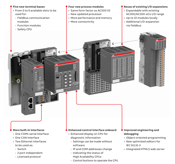
AC500 V3 is the third-generation programmable logic controller launched by ABB. As a technological iteration product of the AC500 series, its core positioning is to bridge industrial automation and the Internet of Things (IoT). This series extends the original AC500 V2 platform with four new CPUs (PM5630/5650/5670/5675), achieving comprehensive upgrades in performance, connectivity, and network security while maintaining hardware compatibility. Its 

Architectural features are as follows

Processor and Memory: Adopting a new generation processor, the computing speed has been significantly improved. Taking PM5670-2ETH as an example, the bit operation cycle is only 0.002 μ s, which is 10 times higher than the V2 platform. It is equipped with 160MB program memory and 8GB flash drive (PM5675), supporting complex algorithms and data storage.

Dual Ethernet architecture: Two independent Ethernet interfaces onboard, configurable as switches or independent ports, supporting IEEE 802.3 standard, integrated with web servers and multiple industrial protocol stacks, without the need for additional communication modules.

Core technical characteristics

1. Performance and computational capability

Instruction efficiency: Supports bit/word/floating-point operations, with the floating-point operation cycle shortened from 0.120 μ s in V2 to 0.002 μ s (PM5670), meeting the requirements of high-speed closed-loop control.

Memory allocation: Programs, data, and web memory are independently partitioned, supporting dynamic allocation. It can run up to 200+task instances simultaneously and is suitable for multi axis motion control and complex logical operation scenarios.

2. Industrial communication and protocol support

Fieldbus integration:

Control layer: Built in CANopen master station, Ethernet IP (under development) Modbus TCP/RTU, Supports PROFINET and EtherCAT (requires module expansion).

Management: OPC UA Server supports data access and alarm services, MQTT client connects to cloud platform through TLS encryption to achieve device data cloud (such as ABB Ability) ™ Platform).

Special fields: KNX (Building Automation), BACnet (Intelligent Buildings), IEC 61850 (Substation Communication) and other protocols are activated through license to adapt to cross industry requirements.

Network topology flexibility:

Dual ports can be configured as “redundant ring network” or “three-layer routing”, for example, port 1 connects to the factory intranet (OPC UA), and port 2 connects to the Internet (MQTT), supporting port mirroring and traffic monitoring.

3. Network security design

Firmware protection: Hardware security chips implement firmware digital signatures to prevent malicious tampering; The transmission of engineering files adopts AES encryption and is integrated with ABB Ability ™  Two way certificate authentication is required for Automation Builder.

Communication encryption: HTTPS/FTPS is used for file transfer, OPC UA supports role-based access control (RBAC), MQTT messages are encrypted through TLS 1.2 to block man in the middle attacks.

Special Version: AC500-XC V3 (Extreme Environment Type)

Designed for harsh industrial scenarios, with multiple environmental adaptability certifications:

Climate adaptability:

Temperature: -40 ° C to+70 ° C for continuous operation, meeting the needs of cold storage and metallurgical high-temperature areas.

Humidity: 100% humidity+condensation protection, meets G3 level corrosion standards, suitable for offshore platforms and chemical workshops.

Mechanical reliability:

Vibration: 4g root mean square random vibration (500Hz), 2g sine vibration, tested according to IEC 60068-2-6, suitable for construction machinery.

Altitude: 4000 meters (620hPa pressure), supporting the application of power stations in high-altitude areas.

Engineering Tools and Development Process

​ABB Ability ™  Automation Builder

Integrated development: integrating PLC programming (IEC 61131-3), safety logic (Safety PLC), HMI configuration, driver debugging, supporting cross device collaborative development.

Simulation and testing: Offline simulation function (under development) can simulate CPU operation, verify program logic without hardware, and shorten debugging cycle.

Version control: Built in Subversion client, supports collaborative development among multiple people, automatically records code change history, and reduces project risks.

ABB SYNCHROTACT ® 5 Synchronous and Parallel Devices

Product overview

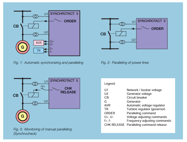
Positioning and Function: SyncHROTACT ®  5 is the fifth generation synchronous equipment produced by ABB Switzerland, used for automatic synchronization of generators and power lines, as well as parallel connection of synchronous lines. It is designed for fully automatic operation of dual channel or single channel systems and can be used as a manual parallel monitoring element or an independent fully automatic synchronization unit to ensure safe and reliable synchronization.

Application scenarios: including automatic synchronization and parallel connection of generators and power lines, automatic parallel connection of synchronous and asynchronous lines and busbars, automatic or manual parallel monitoring (synchronous inspection) of power lines, generators, and voltage free lines (no-load busbars).

Security and usability design

Safety design:

Dual channel system: adopting a compact dual channel system, including two hardware and software independent devices connected in series, the first channel performs automatic synchronization, and the other is independently monitored, designed by different engineers and using different microprocessors to prevent systematic failures.

Manual synchronous monitoring: Manual synchronization is ensured by connecting the monitoring device (synchronous check) in series with the manual parallel switch to ensure safety.

Usability Design: Provides multiple redundant configurations, such as a dual channel main synchronization system with manual parallel switch bypass synchronization system and synchronization check parallel, or two automatic dual channel systems, to achieve the highest safety and maximum availability. The dual channel, automatic channel, and single monitoring channel systems are each housed in one enclosure, while the redundant dual channel system is housed in one enclosure with interconnecting wiring.

Function and Type

Special function: It can store up to seven sets of parameters from different parallel points, with freely configurable digital inputs and outputs. It supports rated frequencies of 50Hz, 60Hz, and 16 2/3Hz and can replace the old SYNC HROTACT system or other manufacturers’ synchronization units.

Reduce engineering costs: The output contacts can carry higher currents, reduce the need for auxiliary relays, isolate all I/O, eliminate the need for a separate power unit, have prefabricated units to choose from, and reduce wiring through a bus control system.

Quick debugging: Use the “SynView” software to recommend parameter values and display ranges. The system includes an intelligent program that can recommend parameters based on generators, circuit breakers, etc., or control debugging through the front panel.

Easy to integrate: It can be easily integrated into modern bus control systems, with communication interfaces supporting MODBUS RTU, Profibus DP, or LON Bus protocols, while maintaining independent protection modules.

Remote maintenance: provide a remote maintenance interface, and communicate with TCP/IP protocol through the Ethernet interface after obtaining the IP address. The PC software “SynView” can directly access the device through the Internet.

Equipment types: including SYN 5100 for simple synchronization check, SYN 5200 for advanced functionality, SYN 5201 for single channel automatic synchronization with frequency and voltage regulation, SYN 5202 for dual channel automatic synchronization system with series synchronization check, SYN 5302 for redundant automatic dual channel synchronization system, and SYN 5500 for auxiliary equipment connecting multiple parallel points.

SynView tool

Function: Used for simple and fast debugging of SYNC HROTACT 5 devices, supports German, English or French, runs on Microsoft Windows 95, 98, 2000 or NT systems, and has four main functions: parameter setting, actual value display, transient recorder function, event and error recording, etc.

Technical Parameter

Power supply and power consumption: The nominal voltage range includes 24/48V DC, 100-125V AC/DC, 220-250V, and the allowable voltage range is DC 0.75-1.25 × Un. The maximum power consumption (SYN 5302) is 25W/35VA.

Measurement input: nominal voltage range 50-130V AC, allowable voltage range 0-1.3 × Un, nominal frequency 16 2/3/50/60Hz.

Digital input and relay: The digital input current consumes DC 6-8mA, the maximum switching voltage of parallel relays is 250V AC/DC, and the maximum switching current is continuously 5A. The maximum switching voltage of adjustment, command, and signal relays is 250V AC/DC, and the maximum switching current is continuously 1.5A.

Measurement range: Voltage 0-1.3 × Un, angle matching from α -179 to+180 degrees, frequency 10-100Hz, slip s0-50%, acceleration ds/dt0-10%/s, parallel time tON0-1s.

ABB SUE 3000 high-speed switching device

Product overview

Positioning and Function: The SUE 3000 is a high-speed switching device mainly used to automatically switch to a backup power source in case of power interruption or voltage drop to ensure continuous power supply for users, protect auxiliary processes from expensive downtime, and also support manual start-up switching to simplify device operation.

Application scenarios: Suitable for occasions sensitive to power outages, such as auxiliary facilities in power plants (steam, gas turbines, combined cycles, nuclear power plants), environmental protection technology facilities (flue gas purification, waste incineration), continuous industrial processes (chemical plants, highly automated industrial facilities, fiber manufacturing, petrochemical processes), etc.

Switchgear configuration

Dual circuit breaker configuration (variant 1): commonly used in auxiliary facilities of thermal power plants. Under normal circumstances, one of the two power sources is supplied by the busbar, and the other is disconnected. It is not allowed for both to supply power simultaneously. In case of a fault, it switches to the second power source. The device is designed symmetrically and can be started and switched from either side.

Two line, one bus configuration (variants 2 and 4): The load is divided into two sections of busbars due to redundancy, and the contact circuit breaker is usually disconnected. Both lines are running. When one line fails, it switches from the fault line circuit breaker to the contact circuit breaker, and can be manually switched back after the fault line is restored.

Three line two option configuration (variant 3): Used for situations where three lines are needed and two options are available, only switching between the pre selected two lines, with fixed input signal connections, and pre selection logic can be combined with additional logic conditions.

Triple line selection configuration (variant 5): When the triple line is available, switching operations can be performed between any two lines. The input signal is hard wired, and the selection logic can be associated with other logic conditions.

Core functions

Working mode: Equipped with fast processing logic and high-precision analog signal processing, it permanently compares the bus voltage with the backup power supply voltage, generates synchronization standards such as phase angle, frequency difference, backup power supply voltage, and bus voltage, ensuring the shortest switching time during startup and reducing transient effects on users.

Permanent determination of network conditions: synchronous standard online calculation, with a determined switching mode at startup, can be started immediately to increase the probability of rapid switching, and the device is only ready when the two circuit breakers are in different states and in their working positions.

Switch Mode

Quick switching: Both the main power supply and the backup power supply are executed within the specified limits during startup, with two types of control: simultaneous control and sequential control. The no current switching time controlled simultaneously depends on the time difference between circuit breaker operation. Sequential control requires waiting for the disconnection indication of the incoming circuit breaker before issuing the command to close the backup circuit breaker.

First phase coincidence switching: When there is no synchronization condition during startup, disconnect the original incoming line first, determine the first phase coincidence point and the time when the closing command is issued through predictive calculation, and connect the backup power supply when the voltage difference is minimized. Careful engineering design and debugging are required.

Residual voltage switching: Used when the first phase coincidence switching is not feasible. When the bus voltage drops to the preset allowable value, connect the backup power supply without evaluating the angle or frequency difference. Transient effects are controllable.

Timed switching: Quick switching is executed when it is not completed within the preset time, which belongs to the safe stage and generally does not occur under normal operating parameters.

Special support functions: including decoupling (automatically reversing to avoid illegal network coupling when mechanical faults are detected), circuit breaker tripping switching (monitoring the position of the circuit breaker and performing switching when disconnected for no reason), and non independent network switching mode (using a programmed time frame to determine if the backup power source is ready).

Configuration and Parameters

Configuration method: LED indicators, single line diagrams, control schemes, automation sequences, etc. are configured through software functional modules. FUPLA programming language is used to provide multiple logic functional modules, and parameters can be modified through HMI control units or connected to configuration computers.

Variable functional parameters: including frequency difference for quick switching, network angle, bus voltage value, backup power supply voltage value, maximum frequency gradient for initial phase coincidence switching, bus residual voltage value for residual voltage switching, original power undervoltage value and delay time for undervoltage startup, timed closing command time, circuit breaker command delay time, etc.

Fault recording: Equipped with a fault recording module, it can record analog and binary data. The analog signal sampling rate is 1.2kHz, and the recording time includes pre trigger and post trigger times. It is stored in a circular buffer and can be exported for analysis.

Operation interface

LCD display: Backlit LCD display, with a single line diagram on the left and measurement values, menus, protection signals, and event records on the right. It can display up to eight switch device icons and other motor, transformer, and other icons.

Status indication: including operating status (green LED “Ready”), communication status (green LED, turns red in case of fault), alarm indication (red LED), interlock status (unused).

1VCR007346028 | ABB

ABB REF542plus multifunctional protection

Product positioning and system architecture

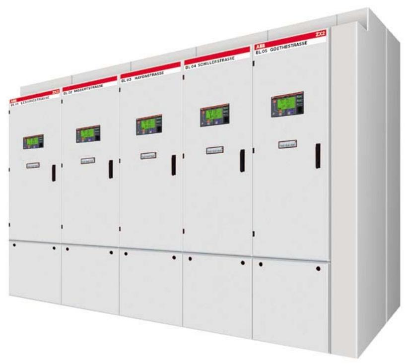
REF542plus is a new generation of intelligent electronic device (IED) for medium voltage distribution systems launched by ABB, designed specifically for scenarios such as gas insulated switchgear (GIS) and air insulated switchgear (AIS), integrating protection, measurement, control, monitoring, and power quality analysis functions. Its core architecture adopts a three processor separation design:

DSP (Digital Signal Processor): Independently executes protection algorithms and high-precision measurements to ensure that fault response is not affected by control tasks.

MC (microcontroller): handles switch control, logic interlocking, and automation sequences, supporting FUPLA graphical programming.

CP (Communication Processor): Supports protocols such as IEC 61850, Modbus, DNP3, etc., to achieve high-speed data exchange with substation automation systems.

Hardware is divided into central unit and HMI control unit:

Central unit: including power module, I/O interface (analog/binary) and optional communication board, supporting standard chassis (2I/O board+1 communication board) or wide chassis (3I/O board+1 analog output board).

HMI control unit: independently installed on the switchgear door panel, equipped with backlit LCD, 8 operation buttons, 3 sets of LED light columns, and electronic key interface, supporting RS485 communication with the central unit.

Core Function Analysis

1. Protection function system

REF542plus supports over 20 protection algorithms, covering all fault types in the entire distribution network scenario:

Overcurrent protection: three-stage non directional overcurrent (50/51), two-stage directional overcurrent (67), supporting ANSI/IEC inverse time characteristics (Normal/Very/Extreme inverse), starting accuracy ± 1.5%, instantaneous response time<16ms.

Ground fault protection: Directional grounding (67N) is based on the Io UO phase criterion, while non directional grounding (51N) supports admittance type protection (Yo criterion), suitable for ungrounded/resonant grounding systems, with a sensitivity of 0.01mS.

Voltage and frequency protection: three-phase overvoltage/undervoltage (59/27), residual overvoltage (59N), frequency anomaly (81), supports df/dt change rate monitoring to prevent system oscillation.

Equipment specific protection: Transformer differential (87), motor stalling (51LR), thermal overload (49), supporting thermal memory function and environmental temperature compensation.

Arc protection: 3-channel optical sensor input, combined with current criterion, can quickly trip within 9ms, reducing the risk of damage caused by switchgear faults.

2. Measurement and monitoring capabilities

Direct measurement: 8-channel analog input (3 sets of current/voltage), supporting traditional CT/PT or Roche coil/resistive voltage divider sensors, with accuracy up to Class 1 (measurement)/Class 3 (protection).

Calculation parameters: line voltage, positive and negative sequence components, active/reactive power, power factor, electrical energy, supporting maximum demand recording and historical data storage.

Equipment status monitoring: mechanical life counting of circuit breakers, spring energy storage status, SF6 gas pressure monitoring, assisted by event recording (30 recent events) and fault waveform recording (5 x 5s, 1.2kHz sampling) for fault analysis.

3. Control and Automation

Local/remote control: Circuit breaker opening and closing can be achieved through HMI buttons or station control system, supporting electronic key permission management (protection parameter setting/control mode switching).

Interlocking and Automation Sequence: Based on FUPLA programming, cross interval interlocking (such as interlocking between bus tie switch and incoming switch), automatic reclosing (three-phase primary/secondary reclosing), and synchronous inspection (25) are implemented to meet the requirements of power grid interconnection.

Technical parameters and interface characteristics

Electrical parameters

Analog input:

CT input: 1A/5A, dynamic range 0.5-200In, supports Roche coil( 150mVrms@In ).

PT input: 100V (compatible with 110V), supports resistive voltage divider( 2Vrms@Un ).

Binary I/O:

Mechanical relay output: 8A/250VAC, supports coil breakage monitoring.

Static output: 12A/265VDC (short-term), suitable for motor drive.

ABB Relion REF615 feeder protection and control device

Product overview

Positioning and Function: REF615 is an intelligent electronic device (IED) designed specifically for public substations and industrial power system feeders, used for the protection, control, measurement, and monitoring of radial, ring, and mesh distribution networks (including distributed generation). It is a Relion ®  The members of the 615 protection and control series products adopt compact and withdrawable unit designs, fully leveraging the potential of the IEC 61850 standard for communication and interoperability between substation automation equipment.

Core Capability: Provides primary protection for overhead lines and cable feeders, and can also serve as backup protection for independent redundant protection systems. Based on selected standard configurations, it is suitable for protecting overhead lines and cable feeders in isolated neutral points, resistance grounding, compensation, and solid-state grounding networks. After configuring specific parameters, it can be directly put into use and supports multiple communication protocols.

Standard configuration

Configuration type: REF615 has 8 standard configurations, and different configurations have different combinations of protection functions. For example, A and B configurations include non directional overcurrent and directional ground fault protection, while C and D configurations include non directional overcurrent and non directional ground fault protection.

Function support: The standard signal configuration can be changed through the graphical signal matrix or optional graphical application function of PCM600. Its application configuration function supports the use of various logic elements (including timers and triggers) to create multi-layer logic functions, combining protection functions with logic function blocks to adapt IED configuration to user specific application needs.

Protection function

Main protection function: Provides directional and non directional overcurrent, thermal overload protection, as well as directional and non directional ground fault protection. According to standard configuration, admittance type ground fault protection can replace directional ground fault protection, and also has sensitive ground fault, phase to phase open circuit, transient/intermittent ground fault, overvoltage and undervoltage, residual overvoltage, positive sequence undervoltage, and negative sequence overvoltage protection functions.

Additional protection function: The standard configuration H of the IED provides frequency protection (including over frequency, under frequency, and frequency change rate protection), enhanced by optional hardware and software, with three optical detection channels for metal enclosed indoor switchgear circuit breakers, busbars, and cable room arc fault protection. The arc fault protection sensor interface is on the optional communication module.

Application scenarios

Network type: Can be equipped with directional or non directional grounding fault protection. Directional grounding fault protection is mainly used for isolated neutral points or compensating networks, while non directional grounding fault protection is suitable for direct or low impedance grounded neutral point networks, and can be used for ring and mesh distribution networks as well as radial networks containing distributed generation.

Specific applications: Different standard configurations are suitable for different scenarios, such as standard configuration G containing one conventional residual current input and three sensor inputs, suitable for compact medium voltage switchgear with limited space, and standard configuration H suitable for industrial power systems, etc.

Supported ABB solutions

System integration: The 615 series of protection and control IEDs and COM600 station automation equipment form a true IEC 61850 solution for reliable power distribution in public and industrial power systems. Through the provided connection package, IEDs can be easily configured and integrated with COM600 or MicroSCADA Pro network control and management systems through the PCM600 protection and control IED manager.

Communication and Functionality: The 615 series IEDs natively support the IEC 61850 standard, including binary and analog level GOOSE message passing. The COM600 provides enhanced substation level functionality using interval level IEDs for data content, with a web-based HMI and gateway functionality, providing seamless connectivity between substation IEDs and network level control and management systems.

Control function 

Circuit breaker control: The IED provides control over a circuit breaker, equipped with dedicated buttons for opening and closing the circuit breaker. The optional large graphic LCD includes a single line diagram (SLD) indicating the position of the circuit breaker, and the interlocking scheme required for the application is configured through the signal matrix or application configuration function of PCM600.

Synchronization check: According to the standard configuration, the IED also includes a synchronization check function to ensure that the voltage, phase angle, and frequency on both sides of the disconnected circuit breaker meet the conditions for secure interconnection between the two networks.

Measurement and recording function

Measurement parameters: Continuously measure phase current, current symmetry component, and residual current. If voltage measurement is included, residual voltage, phase voltage, and voltage sequence component are also measured. According to the standard configuration, frequency measurement is also provided to calculate the current demand value within the user’s selectable preset time frame, thermal overload of the protected object, and phase imbalance value based on the ratio of negative and positive sequence currents. Three phase power and energy measurement, including power factor, are provided.

REF615 | ABB | Feeder Protection

Bentley 3500/45 Position Monitor

Product Overview and Core Features

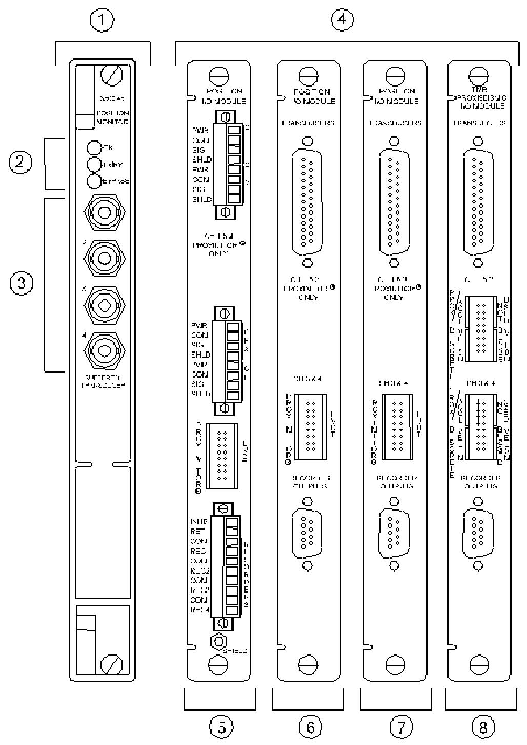
The 3500/45 position monitor is a 4-channel precision monitoring device developed by Bently Nevada, specifically designed for monitoring position related parameters of rotating machinery. Its core function is to receive signals from proximity sensors (Proximitors), rotary position sensors (RPTs), AC/DC linear variable differential transformers (AC/DC LVDTs), and rotary potentiometers. Through signal conditioning and comparison with user programmable alarm thresholds, it achieves mechanical protection and status monitoring.

Core competencies:

Multi parameter monitoring: supports 8 measurement functions including axial (thrust) position, differential expansion, casing expansion, valve position, etc. Channels are programmed in pairs (such as channels 1-2 and 3-4 can perform different functions separately, but casing expansion only supports channels 3-4).

Flexible configuration: Customize the full-scale range, filtering parameters, and alarm thresholds through the 3500 configuration software to adapt to different mechanical operating conditions.

Redundancy design: Supports TMR (Triple Modular Redundancy) configuration, improves system reliability through a 2 out of 3 voting mechanism, and is suitable for monitoring critical equipment.

3500/45-01-CN | Bently Nevada | Position Monitor

Application scenarios:

Used for monitoring parameters such as axial displacement of rotors, thermal expansion difference between shafts and casings, valve opening, etc. in large rotating machinery such as steam turbines and compressors, to prevent equipment failures such as rubbing and overload caused by abnormal positions.

Detailed explanation of technical specifications

1. Input characteristics

Signal type: Supports sensor inputs such as Proximitor (e.g. 3300XL series), DC LVDT (25-508 mm range), AC LVDT (25-254 mm range), rotary potentiometer (50 ° -300 ° rotation range), etc.

Impedance and power consumption:

The input impedance of DC LVDT is 1M Ω, the Proximitor/RPT is 10K Ω, and the rotary potentiometer is 200K Ω.

The power consumption varies depending on the I/O module: typically 7.7W when using position I/O modules, 8.5W for AC LVDT modules, and 5.6W for rotary potentiometer modules.

2. Sensitivity and accuracy

Thrust position: Sensitivity 3.937 mV/mm (100 mV/mil) or 7.874 mV/mm (200 mV/mil), accuracy ± 0.33% of full scale (typical), maximum ± 1%.

Differential expansion:

Standard single slope: Sensitivity 0.394-7.874 V/mm (10-200 mV/mil), accuracy varies depending on the slope angle and range, with a maximum error of ± 2% (such as when the full-scale span is less than 3 Vdc).

Shell expansion: DC LVDT sensitivity is 0.05-0.20 V/mm (1.25-5.00 V/in), AC LVDT is 9.45-28.74 mV/V/mm (0.24-0.73 mV/V/mil).

Valve position: The sensitivity of the rotary potentiometer is 41 mV/degree, the RPT is 50-140 mV/degree, and the AC LVDT is 3.94-28.74 mV/V/mm.

3. Output characteristics

LED indication:

OK light: It lights up when the module is running normally.

TX/RX light: Flashes when communicating with other modules in the rack.

Bypass light: It lights up when the channel is bypassed.

Analog output:

The recorder outputs 4-20 mA, proportional to the full range (such as 20 mA for a full range of 10 mm), with a load resistance of 0-600 Ω, a resolution of 0.3662 μ A/bit, and a temperature drift of ± 0.7%.

Buffer sensor output: 1 coaxial interface per channel, short circuit protection, DC LVDT channel 3-4 offset -10 Vdc, AC LVDT output is the DC characteristic value of the AC signal.

4. Signal conditioning and filtering

Frequency response:

Thrust/differential expansion: Direct filter -3 dB at 1.2 Hz, gap filter -3 dB at 0.41 Hz.

Shell expansion/valve position: Position filter -3 dB at 0.41 Hz, suitable for low-frequency mechanical displacement monitoring.

Alarm mechanism:

The Alert threshold can be set to 0-100% full scale, and the Danger threshold supports any two proportional value configurations, with a time delay of 1-60 seconds (Alert) or 0.1 seconds (Danger), and an alarm accuracy of ± 0.13% of the target value.

Configuration plan and I/O module

1. I/O module types and adaptation scenarios

Module model and function applicable to sensors

01 Internal terminal module directly connects to Proximitors, RPTs, DC LVDTs, suitable for non hazardous areas such as 3300XL series, 25 mm Extended Range, etc

02 External terminal module is connected to external terminal blocks through cables, simplifying rack wiring as above

03 Discrete TMR External Module Triple Redundancy Configuration, with independent sensors for each channel, enhances reliability Proximitor/DC LVDT

05 AC LVDT internal module is dedicated to AC LVDT signal conditioning, supporting a range of 25-254 mm AC LVDT 25 mm/50 mm, etc

The internal module of the 07 rotary potentiometer is compatible with rotary potentiometers (50 ° -300 °) for valve opening monitoring

2. Key points of TMR configuration

Discrete and bus modes:

Discrete mode (module 03): Three independent sensors are connected to three modules respectively, suitable for critical measurements (such as thrust position).

Bus mode (module 04): Single sensor signals are distributed to three modules through the bus, which has lower cost but slightly lower reliability.

Voting mechanism: When the deviation between the output of a module and other modules exceeds the set threshold (such as 5%), an event log is triggered to ensure data consistency.

3. Typical configuration examples

Turbine thrust monitoring:

Sensor: 3300XL 8mm Proximitor with a sensitivity of 200 mV/mil.

Channel configuration: 1-2 channels are set as thrust positions, with a full range of 25-0-25 mil, an Alert threshold of 15 mil, a Danger threshold of 20 mil, and a filtering frequency of 1.2 Hz.

Boiler pipeline expansion monitoring:

Sensor: 50 mm DC LVDT, sensitivity 0.10 V/mm (2.50 V/in).

Channel configuration: 3-4 channels are set for chassis expansion, with a full range of 0-50 mm and an alarm delay of 2 seconds, adapted to the slow change characteristics of thermal expansion.

Ordering and installation information

1. Component numbering rules

3500/45-AXX-BXX:

AXX: I/O module type (e.g. 01=internal terminal, 05=AC LVDT).

BXX: Authentication options (01=CSA/NRTL/C Class I, Div 2).

Example: 3500/45-01-01 represents an internal terminal module with CSA certification.

2. External components and spare parts

Terminal block:

Proximitor/DC LVDT: 125808-06 (Euro interface) or 128015-06 (terminal block).

AC LVDT: 141208-01 (Euro interface), supports signal conditioning and isolation.

Cable:

Sensor to terminal block: 129525 series, length 5-100 feet, supports assembly/non assembly.

Spare parts:

Module spare parts: 176449-04 (3500/45 complete machine), 135137-01 (internal terminal module).

Consumables: 00530843 (I/O module four pin splitter), used for sensor type matching.

3. Installation requirements

Space occupancy: The monitor occupies one full height front slot, and the I/O module occupies one full height rear slot, which needs to be used in conjunction with a 3500 rack.

Environmental compatibility:

Working temperature -30 ° C~65 ° C, storage -40 ° C~85 ° C, humidity ≤ 95% non condensing, in compliance with EN 61000-6-4 electromagnetic compatibility standard.

Explosion proof certification: Equipped with CSA certification module, suitable for Class I, Div 2 Groups A-D hazardous areas, meeting the needs of petroleum, chemical and other scenarios.

Application precautions

Sensor matching:

Differential expansion requires the use of an Extended Range Proximitor (e.g. 25 mm) to ensure that the range covers the expansion difference between the shaft and the casing.

It is recommended to use DC LVDT for casing expansion to avoid AC LVDT phase drift affecting accuracy.

Software version requirements:

TMR configuration requires 3500 configuration software 2.41 or above, and when using RPT for valve position, software 3.00 or above is required.

Maintenance suggestion:

Regularly verify the alarm function (such as triggering Alert/Ranger with input analog signals), and check the consistency between the LED status and the recorder output.

When hot plugging modules, power should be turned off to avoid static electricity damaging the circuit board (it is recommended to wear an anti-static wrist strap).

Summary

The 3500/45 position monitor provides accurate position parameter monitoring for rotating machinery through multi-channel and high-sensitivity design. Its modular configuration and TMR redundancy mechanism ensure system reliability, making it suitable for key fields such as power, petrochemicals, and metallurgy. Users can choose the appropriate combination of I/O modules and sensors based on the type of machinery and monitoring requirements, and achieve customized protection solutions through flexible software configuration, providing data support for the safe operation of equipment.

Bentley 3500/42 Proximitors ®/ Earthquake monitoring module

Product Overview

Core functions

3500/42 Proximitor ®/  The earthquake monitoring module is a four channel monitoring device that can receive input signals from a proximity probe and seismic sensors, and achieve monitoring functions such as radial vibration, thrust position, eccentricity, differential expansion, acceleration, and velocity through configuration. Its core function is to drive alarm output by comparing the current machine vibration value with the preset alarm threshold, and provide machine status data for operation and maintenance personnel.

Key Features

TMR architecture: Supports triple modular redundancy (TMR) configuration, avoids single point of failure through a 2 out of 3 voting mechanism, and ensures system reliability.

Flexible configuration: Customize channel types, alarm thresholds, filtering parameters, etc. through 3500 rack configuration software to adapt to different monitoring scenarios.

Real time diagnosis: Built in self checking function, quickly locate faults through LED indicator lights and event logs.

Safety certification: Compliant with standards such as IEC 61508, suitable for hazardous areas (such as Class I, Division 1/2).

Product Architecture and Working Principle

Hardware Architecture

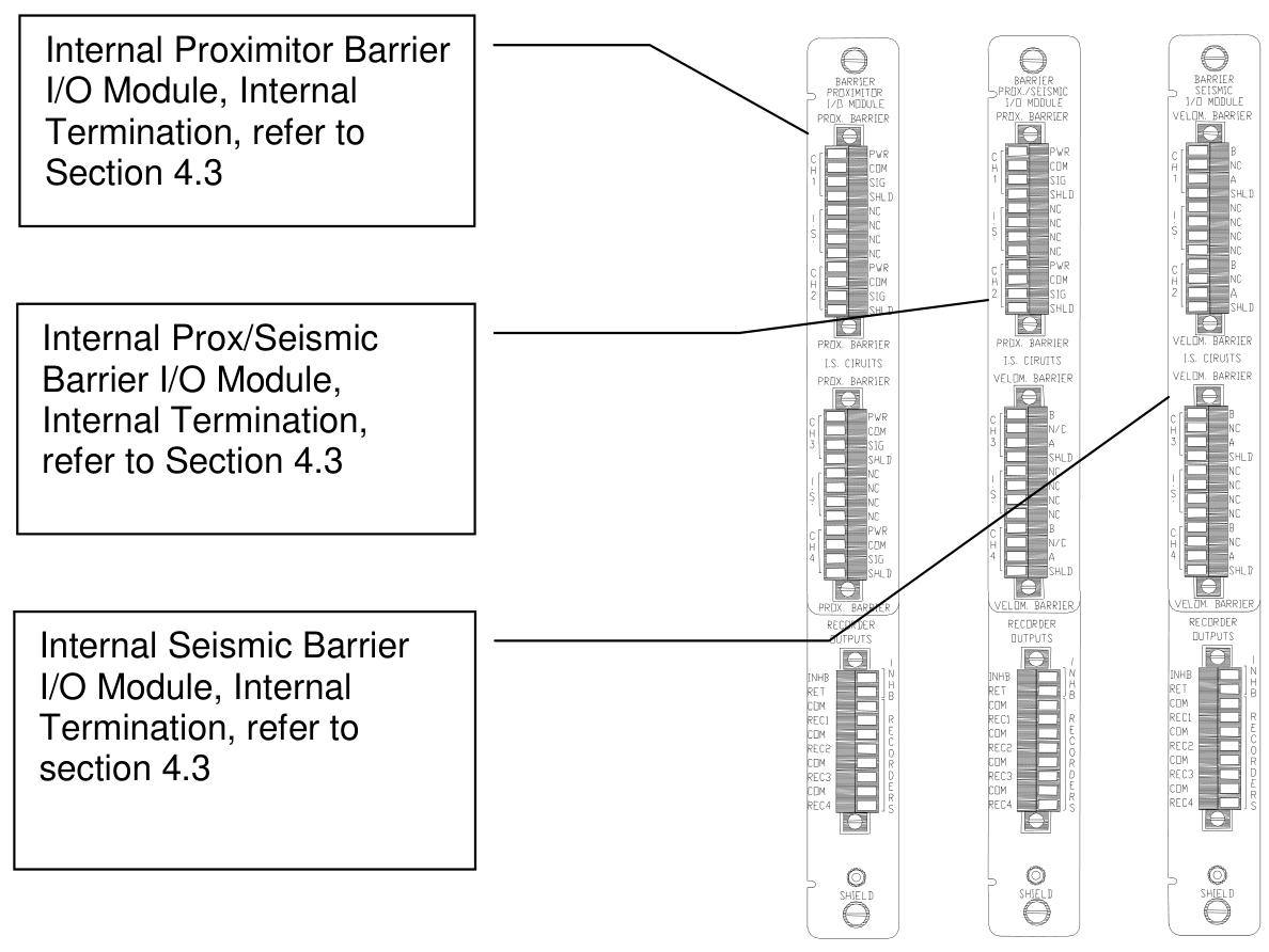
Input module: support multiple I/O modules, including internal terminal, external terminal, TMR terminal and terminal module with barrier, and adapt to different sensor wiring requirements (such as Proximitor, accelerometer, speed sensor).

Signal processing: Each channel integrates filtering, amplification, and digitization circuits, supporting bandpass, high pass, and low-pass filtering, with a configurable frequency response range (such as radial vibration channels supporting 1 Hz to 4000 Hz).

Communication interface: communicates with other modules through the rack backplane, supports serial protocols such as RS-232/485, and can be connected to the upper computer for data monitoring.

TMR redundancy mechanism

Voting logic: In the TMR configuration, three monitoring modules vote 2 out of 3 for the input signal. If the deviation between the output of one module and that of other modules exceeds the set threshold (such as% Comparison), event logging will be triggered.

Input configuration:

Bus configuration: A single non redundant sensor signal is distributed to three modules through the bus.

Discrete configuration: Three redundant sensors are connected to three modules respectively to improve reliability.

Data output and status monitoring

Proportional value output: Output different parameters based on channel type, such as Direct (peak to peak), 1X/2X amplitude, phase lag, etc. for radial vibration; Gap (gap voltage) and Direct (axial displacement) at the thrust position.

Status identification: Feedback module health status, communication status, and alarm events through LED (OK, TX/RX, BYPASS) and event logs (System Event List, Alarm Event List).

Configuration Guide

Software Configuration Tool

Use 3500 Rack Configuration Software for parameter settings, with core configuration items including:

Channel type: Select radial vibration, thrust position, etc. Different types correspond to different filtering and scaling factors.

Full range: For example, radial vibration Direct can choose 0-10 mil pp (peak to peak), and acceleration can choose 0-20 g pk (peak to peak).

Alarm threshold: Set the Alert/Alarm 1 and Danger/Alarm 2 thresholds for each proportional value, and support lag adjustment (e.g., hysteresis is 1/64 of full scale).

Filter parameters: Set the cut-off frequency of the high/low-pass filter (e.g. acceleration channel supports 3 Hz to 30 kHz).

Example of Key Parameter Configuration

Radial vibration channel:

Select a 3300-8 mm Proximitor sensor and set the Scale Factor to 200 mV/mil.

Set the 1X Amplitude full-scale to 10 mil pp, the Alert threshold to 6 mil pp, the Danger threshold to 8 mil pp, and the delay time to 1 second.

Thrust position channel:

The Zero Position voltage is set to -9.75 Vdc (corresponding to the center value of the gap), the full range is set to 25-0-25 mil, and the direction is set to “Forward Probe” (displacement increases when the rotor moves towards the probe).

Key points of TMR configuration

Three monitoring modules need to be installed adjacent to each other and configured with Comparison Voting (if comparing 1X Amplitude, a deviation of 5% is allowed).

Bussed External Termination Block is used for bus configuration, while three independent sensors and terminal blocks are used for discrete configuration.

I/O modules and wiring

Module type and function

Internal terminal module: directly connected to sensors and recorders, suitable for non hazardous areas, wiring should pay attention to electrostatic protection (such as using anti-static wrist straps).

Internal Barrier Module: Integrated Zener Barrier, suitable for explosion-proof areas (such as Class I, Division 1), to restrict energy flow into hazardous areas.

External terminal module: Connect the sensor with a 25 pin cable and the recorder with a 9-pin cable to simplify the internal wiring of the rack.

Wiring specifications

Proximitor sensor: The power supply (PWR) is connected to -24 Vdc, the signal (SIG) is connected to the channel input, and the shielding layer (SHLD) is grounded.

Seismic sensors (such as Velomitor) require series connection of resistors and capacitors (such as 4 k Ω resistors+10 μ F capacitors) for signal conditioning.

TMR wiring: In discrete configuration, three sensors are connected to independent channels of three modules, and in bus configuration, sensor signals are shared through a Bussed Terminal Block.

Maintenance and testing

Regular verification testing

Testing cycle: It is recommended to conduct it once a year. If the equipment is a critical unit or operates in harsh environments, it can be shortened to once every quarter.

Testing equipment: function generator, multimeter, oscilloscope, Keyphasor Multiplier/Diverder, etc.

Test steps (taking radial vibration channel as an example):

Simulate sensor signals (such as a 100 Hz sine wave with a peak to peak value of 2 V).

Verify the display accuracy of proportional values such as Direct and 1X Amplitude (error ≤ ± 1% of full scale).

Trigger Alert/Arm 1 and Danger/Arm 2 thresholds, confirm that the alarm delay time is consistent with the configuration.

Disconnect the input signal and verify the OK state recovery time (Timed OK Channel Defeat set to 30 seconds).

Scale factor and zero position adjustment

Scale Factor: Used to calibrate the linearity deviation of sensors, such as the default 200 mV/mil for 3300-8 mm Proximitors, which can be adjusted by ± 15%.

Zero Position: For channels such as thrust position and eccentricity, adjust the voltage to make the displayed value zero (such as setting the zero position of thrust position to -9.75 Vdc, corresponding to mechanical zero position).

Recorder output verification

The 4-20 mA output should correspond to the full-scale proportional value. For example, when the full-scale is 10 mil pp, 20 mA corresponds to 10 mil pp, and 4 mA corresponds to 0 mil pp, with an error of ≤± 1%.

Troubleshooting

LED fault diagnosis

OK light off: It may be due to module failure, hardware malfunction, or sensor disconnection. Check the power and wiring, restart the module, or replace spare parts.

BYPASS light on: The channel is bypassed by software or the sensor is faulty. Check the Software Switches configuration and confirm that the sensor is in an OK state.

TX/RX light does not flash: communication failure, check the rack backplane connection and serial port parameters (baud rate, data bits).

Analysis of System Event List

Event 11 (Flash Memory Failure): Flash memory failure, module replacement required immediately.

Event 62 (I/O Module Mismatch): The I/O module type does not match the software configuration. Check the module model and reconfigure it.

Event 493 (Kph Lost): Keyphasor signal loss. Check the Keyphasor sensor and wiring to confirm if the speed is within the valid range (60-60000 cpm).

Common alarm handling

Alert/Arm 1 trigger: If the vibration value exceeds the threshold, check whether the machine is unbalanced, misaligned, or has bearing faults.

Trigger of Danger/Arm 2: Emergency stop condition, immediately stop the machine and troubleshoot equipment faults. If the shaft displacement exceeds the limit, it may cause dynamic and static friction.

Technical specifications and ordering information

key parameter

Input impedance: Proximitor channel 10 k Ω, TMR configuration with bus mode 50 k Ω and discrete mode 150 k Ω.

Frequency response: The radial vibration Direct channel supports 1 Hz-4000 Hz, and the acceleration channel supports 3 Hz-30 kHz.

Environmental conditions: Operating temperature -30 ℃~65 ℃ (non barrier module), storage temperature -40 ℃~85 ℃, humidity ≤ 95% non condensing.

Order Parts

Monitor module: 3500/42-01-00 (discrete internal terminal, no authentication), 3500/42-03-01 (TMR external terminal, CSA authentication).

Spare parts: I/O module (such as 128229-01), terminal block (125808-02 Euro style), cable (129525-0010-01, 10 foot assembly cable).

Safety and Compliance

Explosion proof certification: With barrier module supporting Class I, Division 1 (Groups A-D) and EEx ia IIC, suitable for explosive gas environments.

Static protection: When operating the module, wear an anti-static wrist strap and store it in a conductive bag to prevent static electricity from damaging the circuit board.

Maintenance warning: When hot plugging modules, ensure that the rack is powered off to avoid the risk of short circuit or electric shock caused by live operation.

Search for products

Back to Top
Product has been added to your cart