Call us 24/7uaedcs@163.com
Welcome to the official website of CNIACS Automation Technology Co., Ltd!
Call us 24/7uaedcs@163.com

ABB AC 800M Controller Hardware

Product overview

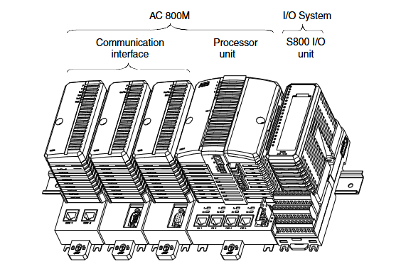
AC 800M Overall: It is a configurable and programmable hardware platform that becomes an AC 800M or AC 800M HI controller after configuration programming, including hardware units such as processor units and high integrity processor units. It can be used as an independent process controller or perform local control tasks in a control network, supporting multiple I/O system connections, requiring firmware loading and application creation using Control Builder M. It is suitable for various applications ranging from small PLCs to advanced DCS. The AC 800M HI controller can run non SIL and SIL classification applications.

Processor unit:

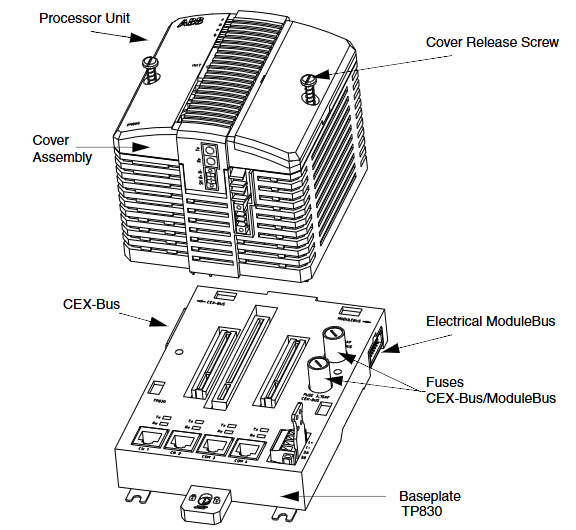
PM8xx/TP830: Composed of a processor unit and a base, the CPU board contains a microprocessor, etc. The power board generates power, and the base has multiple connections. In a single CPU configuration, S800 I/O clusters can be directly connected, and CEX Bus can expand communication ports.

PM891: High performance controller, connected to S800 I/O system through optical Modulus, can run independently or in control network, supports redundant configuration, has multiple interfaces and connectors, including redundant links.

Redundancy: PM861 and other processor units support redundancy, and the controller contains two processor units, one as the main and one as the backup. In case of failure, seamless switching is required, and the system can restore redundancy after replacing the faulty unit. PM86x/TP830 and PM891 each have their own characteristics in redundant configuration.

High integrity: AC 800M can be configured for safety critical applications, with main components such as PM865. PM865 has enhanced internal diagnostics, while SM810 and SM811 each have their own characteristics. The high integrity system’s Module Bus telegram uses the concept of long frames.

Control software: It is the generic name for the functions of a controller, consisting of hardware, firmware, and application program functions, and requires the Control Builder M tool to create applications.

Ethernet address: The TP830 base and PM891 unit of PM8xx (excluding PM891) both have unique Ethernet addresses.

Key features: modularity, easy installation, convenient troubleshooting, protection level, EMC certification, support for multiple I/O and communication protocols, battery backup, CPU redundancy, etc.

Product release history: lists the new content and corresponding user documentation for each version of AC 800M.

Installation

Site planning: Temperature, vibration, cooling, grounding and other site selection and building requirements need to be considered, and there are corresponding specifications for cable laying, power supply and enclosure.

Installation steps: including installing the AC 800M unit onto DIN rails, metal plates, and prefabricated aluminum profiles, as well as installing various processor units in different configurations, CEX Bus related units, various interfaces ModuleBus、 The installation of power supply unit, main circuit breaker unit, voting unit, external battery unit, and I/O unit should also pay attention to the installation in the cabinet and the ventilation installation dimensions.

Configuration

Basic information: Use the Control Builder tool to configure hardware and create applications, with relevant documentation and online help providing information.

Connection and Communication: Introduces the connection methods of Control Builder, the characteristics and connections of control networks, the communication ports and functions of processor units, and the setting methods of controller IP addresses under different configurations.

System configuration: It explains various methods for connecting I/O systems, the composition and connection capabilities of ModulaBus, PROFIBUS DP、PROFINET IO、FOUNDATION Fieldbus HSE、TRIO/Genius Remote I/O、Satt I/O  The relevant configurations, as well as the connection method of ABB drive system and the configuration of power system.

Operation

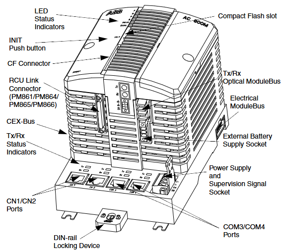
AC 800M Controller (PM8xx): Introduces its composition, functions of LED indicator lights, switches and buttons, as well as the role of connectors.

Startup and Mode: including startup related reference information, redundant configuration startup precautions, operation and characteristics of different startup modes (hot start, cold start, controller reset), and automatic switching to backup CPU.

Operation verification: It explains how to verify the normal operation of AC 800M, including the verification methods for single CPU and redundant CPU.

Maintenance

Preventive maintenance: specifies the frequency and operation of regular system hardware checks, battery replacement, and other preventive maintenance.

Battery replacement: Detailed instructions and precautions for replacing internal batteries, SB821 external battery units, and SB822 rechargeable external battery units.

Online Unit Replacement: Introduces units that can be replaced online and precautions, including CPU replacement under different configurations, online replacement of RCU link cables, etc.

Corrective maintenance: It explains the replacement methods for Module Bus and CEX Bus fuses, as well as the fault finding procedures for various units.

Appendix

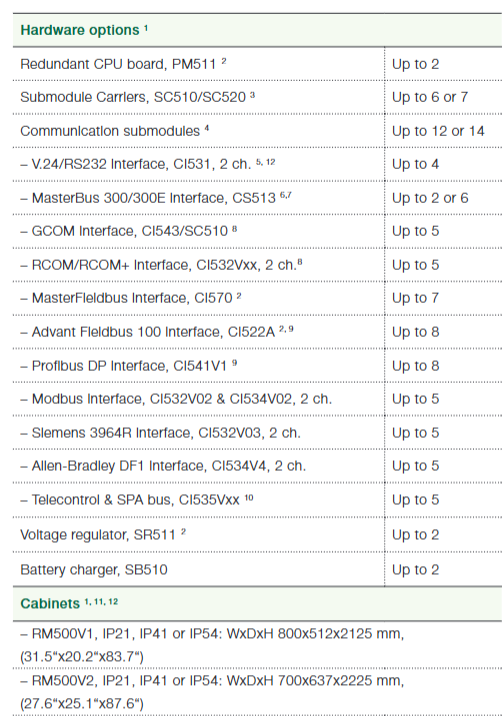
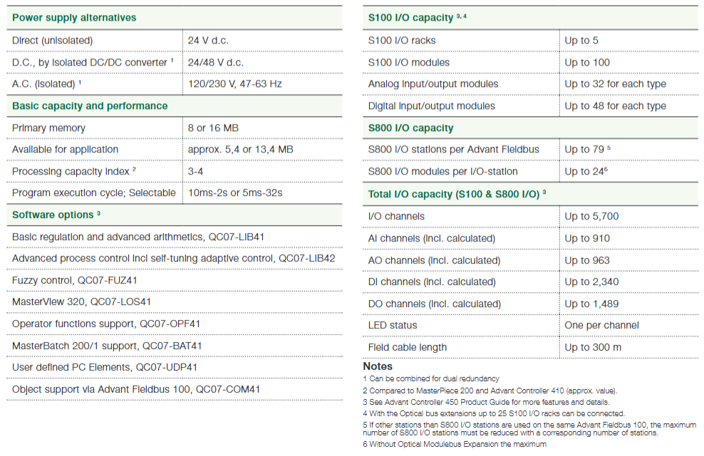
Hardware Unit: Provides detailed information on various processor units, CEX Bus interconnect units, SM810 and SM811, various interfaces, power supply units, voting units, modem units, external batteries, DIN rails, and other key features and technical data of devices.

Power consumption: Provides standard fuse requirements for 40 ° C environment, as well as current consumption and power consumption data for various AC 800M units, as well as related calculation methods and maximum current supply information.

Recommended components: mention relevant recommended component information.

Instruction considerations: involve electromagnetic compatibility and low-voltage instruction related content.

Standard: Includes certification information for hazardous locations.

Environmental data: Provided environmental data for AC 800M products, including climate and mechanical environmental conditions.

ABB ACS1000 series medium voltage frequency converter

Product positioning and core advantages

ACS1000 is a medium voltage AC drive solution launched by ABB, designed specifically for controlling medium and high voltage motors. It covers a power range of 1.1-63 MW and is compatible with voltage levels of 2.3-11 kV. Its core advantages include:

Efficient and reliable: Adopting direct torque control (DTC) technology, the dynamic response is fast (speed step response ≤ 10 ms), the speed regulation accuracy is high (± 0.1% rated speed), and the power factor is ≥ 0.95 (at full load), reducing power grid losses.

Flexible adaptation: Supports multiple motor types (asynchronous motor, synchronous motor), can be configured as a single drive or multi drive system, and adapts to the load characteristics of different industrial scenarios (such as constant torque, variable torque).

High availability: Modular design supports online maintenance, key components such as power modules and cooling systems can be redundantly configured, with a long mean time between failures (MTBF), reducing the risk of downtime.

Environmental Protection and Compliance: The input current harmonic distortion (THD) is low (≤ 5%), and it can meet international standards without the need 

Technical architecture and core components

1. Topological structure

Adopting a three-level NPC (neutral point clamp) inverter design, precise control of voltage and frequency is achieved through IGBT power devices. Compared to traditional two-level topologies, the output harmonics are lower and the motor insulation is friendly.

2. Core components

Power module: including rectifier, inverter, and buffer circuit, divided into different frame sizes according to power level (such as Frame 1-6), supporting parallel expansion.

Control unit: Based on ABB DTC technology, integrated PLC function, supports logic control, sequence control, and PID regulation, and can be operated through Panel Control panel or upper system.

Cooling system: Provides two solutions: air cooling (AC) and water cooling (WC). Water cooling is suitable for high power density scenarios (such as 10 MW or more) and supports connection to heat exchangers or cooling towers.

Auxiliary equipment: optional EMC filters, input isolation transformers, braking units, sine wave filters (to reduce motor harmonic losses), etc.

Model specifications and performance parameters

1. Power and voltage range

Voltage level (kV) Power range (MW) Suitable motor current (A) Typical application scenarios

2.3 1.1-18 300-4500 fans and pumps

3.3 1.5-25 250-4800 Compressor and Conveyor Belt

4.16 2.0-30 300-4200 rolling mill and crusher

6.6 3.0-40 250-3500 Mine Hoist

11 5.0-63 250-3200 Large pump stations, power plant auxiliary equipment

2. Key Performance

Speed range: 1:1000 (closed-loop control), 1:100 (open-loop control).

Overload capacity: 110% rated load for 60 seconds, 150% rated load for 2 seconds (applicable for starting impact loads).

Efficiency: ≥ 97% under rated load (including isolation transformer).

Protection level: Power unit IP21/IP23 (air cooling), IP54 (water cooling), control cabinet IP42/IP54.

Application scenarios and typical configurations

1. Main industry applications

Electricity: boiler fan, feedwater pump, condensate pump, desulfurization system.

Metallurgy: main drive of rolling mill, coiler, blast furnace fan.

Oil and gas: oil pumps, compressors, and natural gas pipeline pressurization.

Water treatment: large sewage pumps, water supply booster pumps.

Mining: Mine hoist, crusher, scraper conveyor.

2. Typical configuration examples

Standard configuration for fans/pumps: ACS1000 host+air cooling+input isolation transformer+MODBUS communication.

High precision transmission configuration: ACS1000 host+water cooling+encoder feedback+PROFIBUS-DP+sine wave filter.

Service and Support

Full lifecycle services: including installation and commissioning, training, preventive maintenance, remote monitoring (through ABB Ability) ™ Platform, spare parts supply, etc.

Customized solution: Cabinet layout, interface protocols (such as PROFINET, EtherNet/IP), redundant configuration, etc. can be designed according to customer needs.

ABB ACS800-31/U31 series transmission module

Product Overview and Core Features

Positioning: Wall mounted low harmonic AC drive module, used to control AC motors, supports multiple voltage levels (208-690 VAC), suitable for industrial automation scenarios such as fans, pumps, conveyors, etc.

Core advantages:

Adopting direct torque control (DTC) technology, supporting high-precision speed and torque control.

Integrating the input side rectifier and motor side inverter, energy conversion is achieved through IGBT modules, with low input current harmonic distortion (THD).

Support multiple extension functions (such as brake chopper, EMC filter, anti misoperation device), suitable for complex industrial environments.

Technical parameters and specifications

1. Rated performance

Power range: 5.5-110 kW (IEC standard), 7.5-125 HP (NEMA standard).

Voltage and frequency: Supports three-phase 208/230/400/480/690 VAC, frequency 48-63 Hz.

Overload capacity:

Light overload: Allow 10% overload for 1 minute every 5 minutes.

Heavy overload: 50% overload is allowed every 5 minutes for 1 minute.

Efficiency: Approximately 97% at rated power.

2. Structure and Protection

Dimensions: available in R5 (width 265 mm) and R6 (width 300 mm), with protection levels of IP21 (UL Type 1) or IP20 (UL Type Open).

Cooling method: forced air cooling, air flow rate of 350-405 m ³/h, noise level of 70-73 dB.

3、 Hardware composition and interfaces

Core module:

Incoming side rectifier: Rectify AC power into DC power, including EMC filter (optional) to suppress harmonics.

Motor side inverter: Convert DC power into adjustable frequency AC power to drive the motor to operate.

Control board (RMIO): Provides digital/analog I/O, relay output, communication interfaces (such as DDCS fiber optic communication), and supports fieldbus expansion (PROFIBUS, MODBUS, etc.).

Key interfaces:

Power interface: input (U1/V1/W1), output (U2/V2/W2), braking circuit (UDC+/UDC -).

Control interface: Analog input (0-10 V/4-20 mA), digital input (6 channels), relay output (3 channels), control panel interface (CDP312R).

Installation and wiring

1. Mechanical installation

Support wall mounted or cabinet installation, with reserved cooling space (at least 50-200 mm around) to avoid vibration and high temperature environments.

Weight: R5 is about 65 kg, R6 is about 100 kg, and lifting devices are required for handling.

2. Electrical installation

Power cable: Shielded cable is required, with a cross-sectional area selected according to the current (6-185 mm ²), and the shielding layer needs to be grounded 360 ° to reduce electromagnetic interference.

Control cable: For analog signals, it is recommended to use double shielded twisted pair cables, while for digital signals, single shielded cables should be used to avoid parallel wiring with power cables.

Grounding requirements: Strictly follow the PE grounding specifications, and the cross-sectional area of the grounding conductor should not be less than 1/2 of the phase line (or 16 mm ², whichever is larger).

Safety and Maintenance

Safety Notice:

High voltage warning: After power failure, wait for 5 minutes to confirm that the capacitor has discharged completely (voltage<50 V) before operation.

Static protection: When handling printed circuit boards, it is necessary to wear a grounding wristband.

Anti misoperation: An optional AGPS board (+Q950) can be used to block power output through an external switch to prevent accidental startup.

Maintenance cycle:

Cooling radiator cleaning: Every 6-12 months (depending on the amount of dust in the environment).

Cooling fan replacement: Every 6 years (approximately 50000 hours).

Capacitor replacement: Every 10 years (affected by ambient temperature).

ABB ACV700 series frequency converter

Scope and purpose of application

Covering the entire range of ACV700 frequency converters, we provide customers and professional recycling institutions with recycling and processing standards that comply with the EU WEEE directive, guiding material separation, disassembly, and environmentally compliant operations.

Product material composition

The ACV700 frequency converter is mainly composed of an incoming line unit (LSU), a capacitor bank unit (CBU), and an inverter unit (INO). The materials for each part are as follows:

Unit, main components, core materials

Incoming unit rectifiers, fuses, circuit breakers, etc. made of copper (Cu), aluminum (Al), steel (Fe), ceramics, plastics (PP, PC, PVC), silver (Ag), nickel (Ni), etc

Aluminum (Al) electrolytic capacitor unit, electrolytic solution

Inverter unit power semiconductor, circuit board and other glass fiber (GF), copper (Cu), tin (Sn), plastic, heat dissipation grease (including silicon, zinc chromium, etc.)

Packaging materials: including wooden pallets, corrugated cardboard, anti-static polyethylene film, VCI rust proof film, etc., all of which are recyclable materials.

Environmental characteristics of production and use

Production management: ABB Oy (Finland)’s production system complies with ISO 9001 (quality) and ISO 14001 (environment) certifications, ensuring environmental compliance in the production process.

Advantages during the usage phase:

Energy saving benefits: By adjusting the motor speed, significant energy consumption can be reduced and operating costs can be minimized.

Optimization control: Accurately adjust speed and torque to enhance process stability.

Extend lifespan: Reduce motor and equipment wear and tear, and lower maintenance requirements.

Product waste disposal and recycling

Handling principle:

Adhere to international and national regulations, prioritize dismantling and separating materials for recycling, and reduce landfill and incineration.

Disassembly method:

Manual disassembly: Separate by material classification (black metal, aluminum, plastic, printed circuit board, electrolytic capacitor, etc.).

Mechanical crushing: Harmful substances (such as electrolytic capacitors) need to be removed first, and then the materials are crushed and sorted using specialized equipment.

Hazardous substance control:

Compliant with the EU RoHS II directive, restricting the use of harmful substances such as lead and mercury, with specific reference to the ABB List of Prohibited and Restricted Substances.

WEEE compliance requirements:

The product is labeled with the “Wheelie Bin” recycling label (with a horizontal line indicating production after 2005), and must be processed through dedicated recycling channels. Mixing with ordinary household waste is prohibited.

Recycling examples and environmental information

Typical recycling methods:

Directly recycling and reusing metal materials such as steel and aluminum; Plastic is used for energy recovery (incineration power generation); Printed circuit boards and electrolytic capacitors are treated as electronic waste; Landfilling of ceramic materials.

Further resources:

More environmental policies, sustainable development goals, and material safety data sheets can be obtained through the ABB official website, or local ABB representatives can be contacted for recycling support.

ABB Advant Controller 31 40&50 Series controllers

Product positioning and core features

The 40 series and 50 series of Advant Controller 31 are small and medium-sized programmable logic controllers (PLCs) suitable for industrial automation scenarios with 14 to 1000+inputs/outputs, featuring the following core features:

Flexibility and Scalability: Supports local expansion (up to 6 binary or analog expansion modules) and remote expansion (up to 31 slave units connected via CS 31 bus), covering single machine control to distributed large-scale systems.

Multi scenario adaptation: widely used in fields such as mechanical control, water treatment, building management, greenhouse environmental regulation, etc., supporting functions such as complex logic control, sequence control, and data processing.

Communication capability: Integrate multiple communication protocols (MODBUS, ASCII, CS 31 bus), support interconnection with upper computer, HMI (such as TC50 display), frequency converter and other devices.

Hardware composition and technical parameters

1. Central unit (40 series vs 50 series)

Features 40 series (such as 07 CR 41, 07 CT 41) 50 series (such as 07 KR 51, 07 KT 51)

Core configuration includes 8 isolated inputs (24V DC), 6 relay/transistor outputs, 8 isolated inputs (24V DC), and 6 relay/transistor outputs, including CS 31 bus interface

Power supply 24V DC or 120/230V AC 24V DC or 120/230V AC

Scalability up to 6 local expansion modules+31 remote slaves (CS 31 bus)

Communication interface RS232 (programming/ASCII/MODBUS) RS232/RS485 (supporting CS 31 bus master/slave mode)

Memory and Backup 17000 Word User Program Memory, RAM with Battery Backup (40 Days) Same as 40 Series, Supports Data Backup and Recovery

2. Expansion module

Binary extensions: such as XI 16 E1 (16 inputs), XO 08 R1 (8 relay outputs), XC 08 L1 (8 configurable I/O), etc., supporting the expansion of binary signal processing capabilities.

Simulation extension: such as XM 06 B5 (4 inputs+2 outputs), XE 08 B5 (8 inputs), supporting signals such as current (4-20mA), voltage (± 10V), temperature (Pt100/Pt1000), etc., with a resolution of 12 bits.

3. CS 31 bus

Physical layer: RS485 shielded twisted pair, maximum transmission distance of 500 meters (without amplifier) or 2000 meters (with 3 amplifiers).

Communication characteristics: master-slave protocol, supporting up to 31 slave stations, with a maximum transmission rate of 187.5 kbps, using CRC8 verification to ensure data reliability.

Programming and Software

1. Programming software and language

AC31GRAF: Supports Windows system, provides programming languages such as ladder diagram (LD), function block diagram (FBD), instruction list (IL), etc., and is compatible with IEC 1131-3 standard.

Core functions: variable declaration, program editing, compilation, online debugging, parameter configuration (such as cycle time, communication mode).

2. Program Structure

Supports the main program, up to 12 sub programs, and interrupt programs (hardware triggered or periodic), enabling complex logic and real-time response.

Built in rich functional blocks: logical operations (AND/OR), timers (TON/TOF), counters (CTU/VRZ), PID regulation, communication control (MODBUS/CS 31), etc.

Communication and Integration

Core Communication Protocol and Interface

CS 31 bus

Positioning: The core bus of distributed control adopts a master-slave architecture (RS485 standard), supporting communication between remote expansion units and central units.

Technical parameters:

Transmission medium: shielded twisted pair (AWG 24-18), maximum length of 500 meters (without amplifier) or 2000 meters (with 3 NCB/NCBR amplifiers).

Communication speed: up to 187.5 kbps, using CRC8 verification to ensure data reliability.

Connectivity: The master station can manage up to 31 slave stations (remote units, expansion modules, third-party devices such as frequency converters, etc.).

Application scenario: Suitable for workshop level distributed control, such as signal acquisition and control instruction transmission at each workstation of the production line.

MODBUS protocol

Support type: MODBUS RTU (master/slave mode), compatible with industrial standard equipment (such as HMI, PLC, frequency converter).

Interface and configuration:

Physical interface: RS232 (40 series) or RS232/RS485 (50 series), connected through a dedicated cable (07 SK 51/53).

Communication parameters: default 9600 baud, 8 data bits, 1 stop bit, no checksum, can be adjusted through software configuration.

Function: Supports reading and writing coils (01/05 function codes) and registers (03/06 function codes), enabling data exchange with upper level computers (such as SCADA) or HMI (such as TC50 displays).

ASCII protocol

Positioning: point-to-point text communication, used for interacting with ASCII devices such as printers and terminals.

Features: Communication parameters (rate, parity, etc.) need to be configured through SINIT functions, support custom message formats, suitable for simple data printing or instruction transmission.

Integration capability and expansion methods

Native Extensions

Connect binary/analog expansion modules through dedicated interfaces, such as:

Binary extensions: XI 16 E1 (16 inputs), XO 08 R1 (8 relay outputs), supporting up to 6 modules.

Simulation extension: XM 06 B5 (4 inputs+2 outputs), XE 08 B5 (8 inputs), supports signals such as current (4-20mA), voltage (± 10V), temperature (Pt100/Pt1000), etc.

Remote integration

Connect remote units (such as ICMK 14 F1/N1) through CS 31 bus to achieve decentralized I/O acquisition and control, suitable for large equipment or long-distance scenarios (such as workshop cross area control).

Support third-party device access, such as ABB ACS series frequency converters (via NCSA-01 interface), high-speed counters (ICSF 08 D1), etc., communicating through CS 31 protocol.

HMI and upper system integration

TC50 monitor: Connected via RS232/RS485, supports 128 page display, parameter modification, alarm prompts, and is compatible with MODBUS protocol.

Programming and Monitoring: Program download and online debugging are achieved through AC31GRAF software (Windows environment), which supports real-time data interaction with PC.

Communication optimization and diagnosis

Redundancy and reliability

The CS 31 bus supports media redundancy (dual cables) and bus redundancy (dual master stations), and achieves automatic fault switching through NCBR amplifiers to reduce the risk of communication interruption.

Communication timeout detection: The master station identifies faulty slave stations through CRC checksum timeout mechanism (default 250ms), triggers alarms, and records error codes.

diagnostic function

Error classification: Divided into 4 levels (fatal error, serious error, light error, warning), the specific cause (such as bus disconnection, address conflict) is displayed through the ERR indicator light and software (AC31GRAF) of the central unit.

Communication status monitoring: Real time monitoring of communication health through variables IW 62.15 (CS 31 bus status) and MW 255. x (MODBUS watchdog).

ABB Advant Controller 410 Process Controller

Product positioning and core advantages

Advant Controller 410 is a medium-sized process controller suitable for binary, regulating, and monitoring control. Its main advantages include:

Comprehensive functionality: supports various functions such as logic control, arithmetic operation, data processing, sequence control, PID regulation, etc., to meet the needs of complex industrial scenarios.

Flexibility and Scalability: Both hardware and software can be flexibly expanded, supporting online configuration and adding modules without interrupting operation.

Strong compatibility: Supports multiple communication protocols (such as MasterBus 300/300E, Advant Fieldbus 100, PROFIBUS-DP, etc.), and can be integrated with I/O systems such as S100 and S800.

High reliability: Supports redundant configurations such as power and communication, with RAM memory backed up by batteries (at least 4 hours) to ensure data security.

Core functions and technical features

1. Control and processing capabilities

CPU and Memory: Based on Motorola 68020 microprocessor (25 MHz), equipped with 4 or 8 MB dynamic RAM with error correction, supporting system program and application program storage.

Programming and Execution: Using ABB Master Programming Language (AMPL), supporting functional block (PC element) programming, program cycle time can be configured (usually 10 ms -2 s, extended 5 ms -32 s).

I/O capacity: Supports up to 4300 I/O points, including analog input (AI), analog output (AO), digital input (DI), and digital output (DO), supporting S100 (local I/O) and S800 (distributed I/O) systems.

2. Communication and Integration

Communication interface: Supports various buses such as MasterBus 300/300E, Advant Fieldbus 100, PROFIBUS-DP, LONWorks, etc., and can connect operator stations, printers, external devices, etc.

Data exchange: Data transmission is achieved through data sets, supporting cyclic and on-demand transmission, and remote communication (such as RCOM/RCOM+, MODBUS).

3. Diagnosis and maintenance

Self diagnosis: equipped with hardware fault detection, communication error monitoring and other functions, displaying system status (such as running, error, timeout, etc.) through LED indicator lights.

Time synchronization: Supports internal clock and external synchronization (accuracy<3 ms), with event time marking accuracy up to 1 ms.

Hardware components

1. Core module

Processor module (PM150V): includes CPU, RAM, program card interface (PCMCIA), submodule slots (supporting communication interfaces, etc.), front panel with status indicator lights and operation switches (start/stop mode).

Power system: Supports 120/230 VAC or 24/48 VDC input, can be configured with redundant power supply (dual power supply+3 voltage regulators) to ensure stable power supply.

I/O system:

S100 I/O: Up to 15 I/O boards, supporting analog, digital, pulse counting, and other signals, placed on the same shelf as the CPU.

S800 I/O: Distributed I/O connected via Advant Fieldbus 100, supporting up to 79 stations per bus and up to 24 modules per station.

2. Expansion and redundancy

Submodule: supports communication interfaces (such as CI531 for RS-232-C, CI541V1 for PROFIBUS-DP), power regulators, etc., and is hot swappable.

Redundant configuration: Power supply, communication bus, CPU, etc. can be redundant to improve system availability.

Software components

Basic and optional modules

Basic module (QC01-BAS11): includes core PC elements such as logic, arithmetic, and data processing, supporting I/O systems and basic communication.

Optional modules:

QC01-LIB11: Extended process control functions (such as PID regulation, filters).

QC01-LIB12: Advanced process control (such as adaptive regulation, ratio control).

QC01-OPF11: Supports operator station functions such as trend display and alarm management.

ABB Advant Controller 450 Controller

Product positioning and core advantages

AC 450 is a process controller suitable for high demand industrial applications, with the main features including:

Upgrade and compatibility: As an upgrade path for MasterPiece 200, it supports a longer lifecycle and can be fully integrated with System 800xA systems.

High performance and scalability: With high processing capabilities, it is suitable for complex applications and can support process expansion while controlling engineering costs.

High availability: Supports redundant backup of communication, power, CPU, and I/O boards to ensure high availability of the factory.

Multi protocol support: compatible with multiple communication protocols such as MODBUS, Profibus, Masterbus 300/300E, Advant Fieldbus 100, etc., facilitating the construction of optimized control system architectures.

I/O Capacity and Configuration

1. S100 I/O capacity

Supports up to 5 S100 I/O racks and 100 S100 I/O modules.

The maximum number of analog input/output modules is 32, and the maximum number of digital input/output modules is 48.

Note: Up to 25 S100 I/O racks can be connected through optical bus expansion.

2. S800 I/O capacity

Each Advant Fieldbus supports up to 79 S800 I/O stations (if there are other stations on the bus, they need to be reduced accordingly).

Each I/O station can have up to 24 S800 I/O modules (without optical expansion).

3. Total I/O capacity (S100+S800)

Total I/O channels: up to 5700.

Analog inputs (including calculated values): up to 910; Analog output (including calculated values): up to 963.

Number input (including calculated values): up to 2340; Digital output (including calculated values): up to 1489.

Other features: Each channel is equipped with LED status indicator lights, and the longest on-site cable length is 300 meters.

Hardware Options

CPU and Redundancy: Up to 2 redundant CPU boards (PM511), supporting dual redundancy configuration.

Submodule carrier: up to 6 SC520 or 7 SC510, totaling up to 8 modules including CPU.

Communication submodule: up to 12 (with redundant CPUs), supporting multiple interfaces:

V. 24/RS232 (CI531, 2 channels): up to 4;

MasterBus 300/300E (CS513): up to 2 (executed by the main CPU) or 6 (executed by the slave CPU);

Advance Fieldbus 100 (CI522A), Profibus DP (CI541V1): up to 8 each;

Modbus, Allen Bradley DF1 and other protocol interfaces: up to 5 each.

Power supply and auxiliary equipment: up to 2 voltage regulators (SR511), 2 battery chargers (SB510).

Cabinet: Provides RM500V1 (IP21/IP41/IP54, size 800 × 512 × 2125mm) and RM500V2 (IP21/IP41/IP54, size 700 × 637 × 2225mm), which can be combined into multiple cabinet groups.

ABB Arc Welding Robot Automation Solution

Core advantages and applicable scenarios

Efficiency and economy: Robot automation can improve welding efficiency, reduce waste, and improve quality. The investment payback period for single or dual robot units can be as short as 6 months, which is not only suitable for long series production in the automotive industry, but also meets the short series or even single piece production needs of small and medium-sized enterprises.

Usability: Simplify programming and operation through specialized software tools, allowing operators to quickly program and reprogram, reducing implementation time.

One stop solution: Provide a complete arc welding package, including equipment and software, to simplify the procurement process, reduce costs, shorten delivery time, and all components are tested in the laboratory to ensure collaborative work.

Main components and functions

1. Robots

Core models: including IRB 140, IRB 1410, IRB 1600 series, IRB 2400 series, IRB 4400 series, IRB 4450S, etc., with a load range of 5-60kg, a working radius of 0.81-2.55m, and a repeat positioning accuracy of 0.03-0.1mm, suitable for different welding scenarios.

Typical applications: IRB 1600 is fast and has a large stroke, suitable for most applications. Its dual robot configuration can cover long workpieces, and when combined with orbital motion (such as RTT 1600), it can expand the operating range.

2. Power sources

MigRob 500: an integrated inverter power supply designed specifically for robot welding, supporting MIG/MAG welding, with a voltage range of 8-60V and a current of 16-500A. It includes 300 ready-made collaborative welding circuits, and the operator can automatically match the voltage after selecting the wire feeding speed.

RPB series: including RPB 320/420/520, current range 10-520A, supports short arc, spray arc, fast arc and other processes, suitable for different load requirements.

3. Positioners

Classification and Parameters: Divided by model into IRBP R/C/L/A/K/B/D series, with a load capacity of 250-5000kg, a maximum diameter of 1000-3200mm, and a maximum length of 900-5000mm, it is used to fix and rotate workpieces, making it convenient for robots to weld in all directions. For example, IRBP K 750 has a load of 750kg, can rotate axially and rotate itself, making it easy to load and unload workpieces.

4. Controller System&Interface

IRC5 controller: Modular control system, supports MultiMove function, can control up to 4 robots to work together or independently, including control module and drive module, with a protection level of IP54.

FlexPendant: Lightweight interface unit, 7.5-inch screen, supports touch operation and joystick control, programmable with 8 buttons for single point programming of robots and power supply, controlling up to 4 robots.

5. Welding gun system and auxiliary equipment

Welding gun system: including gas cooled PSF 315 M and water-cooled PKI-S/PKI-D series, with a current range of 170-500A, suitable for welding wire diameters of 0.8-2.4mm, PKI 500 D can replace Dresspack without disassembling the welding gun, saving time.

Welding Gun Service Center (TSC): Automatic cleaning and lubrication of welding guns, cutting of welding wires, automatic calibration after collision, ensuring uninterrupted welding.

Track motions: such as IRBT 1003S and RTT series, adapted to different robots, with a speed of 0.8-1.8m/s and a repeat positioning accuracy of ± 0.05-0.15mm, expanding the robot’s operating range.

6. Software products

RobotStudio: a simulation and offline programming software that allows for robot programming to be completed in the office without affecting production, making it convenient for MultiMove programming.

ArcWeld PowerPac (AWPP): A plugin for RobotStudio designed specifically for generating arc welding programs, including ready-made welding templates for easy editing by users.

WebWare: a monitoring system that analyzes production trends, identifies fault causes, backs up robot systems, and accesses them through a web interface.

VirtualArc: Offline prediction and adjustment of welding parameters, simulating arcs to predict welding quality, contour, and defects, optimizing productivity and quality.

Typical Configuration Example

1. Dual station long workpiece welding unit (efficient mass production configuration)

Core objective: To achieve parallel loading, unloading, and welding of workpieces through a dual station design, maximizing robot utilization and suitable for welding workpieces up to 4 meters in length.

Component model/specification and function description

Robot IRB 1600 2 robots work together, with a load of 5-7kg, a working radius of 1.2-1.45m, a repeat positioning accuracy of ± 0.05mm, and high-speed welding to ensure efficiency.

The IRBP K 750 displacement machine has a load of 750kg and supports axial rotation of the workpiece (facilitating full angle welding of the robot) and self rotation (achieving dual station switching). The maximum workpiece length is 4000mm and the diameter is 1400mm.

The MigRob 500 power supply integrates IGBT inverter, supports MIG/MAG welding, with a current of 16-500A and 300 collaborative welding parameters, automatically matching wire feeding speed and voltage.

The welding gun system PKI 500 D water-cooled dual interchangeable welding gun can quickly replace Dresspack (without disassembling the welding gun), adapt to welding wire diameters of 0.8-1.6mm, and has a current of 400A at 100% load duration.

The IRC5 modular control system includes one control module and two drive modules, supports MultiMove function, and enables two robots to work independently or collaboratively.

The TSC welding gun service center automatically cleans and lubricates the welding gun, cuts the welding wire, and automatically calibrates after collision to ensure uninterrupted welding.

Workflow:

When the operator is loading and unloading workpieces at workstation A, the robot is welding at workstation B; After workstation B is completed, the positioner rotates to switch workstations, achieving seamless connection.

2. Single robot track configuration (flexible adaptation to long workpieces)

Core objective: Expand the robot’s operating range through orbit, suitable for welding small and medium-sized batches of diverse long workpieces, and reduce equipment investment.

Component model/specification and function description

The IRB 1600+RTT 1600 orbital robot is installed on the track, with a track speed of 1.06m/s and a repeat positioning accuracy of ± 0.05mm. It can cover workpieces up to 6 meters long.

The RPB 520 power supply has a current of 10-520A and supports processes such as short arc and spray arc. It can output 520A at 80% load duration and is suitable for high-strength welding requirements.

The IRBP 500 L displacement machine has a load of 500kg and a maximum workpiece length of 4000mm. It rotates the workpiece horizontally to match the welding angle of the robot.

The software ArcWeld PowerPac uses the RobotStudio plugin to quickly generate welding programs, simplify parameter settings using preset templates, and shorten programming time.

Advantages: The combination of single robot and track reduces costs, and the coordinated control of track motion and robot ensures consistent welding of long workpieces.

3. Compact single workstation configuration (for small and medium batch production)

Core objective: Small footprint, suitable for scenarios with limited workshop space, balancing flexibility and economy.

Component model/specification and function description

Robot IRB 1410 has a load of 5kg and a working radius of 1.44m, suitable for small and medium-sized workpieces, with a repeat positioning accuracy of ± 0.05mm.

The MigRob 500 power supply features an integrated design that saves space and supports pulse arc welding to ensure the quality of thin-walled welding.

The displacement machine IRBP 250 R has a load of 250kg, a maximum workpiece diameter of 1000mm, and achieves multi angle welding through axial rotation.

Interface unit FlexPendant 7.5-inch touch screen+joystick, single point control of robot and power supply, simplifying operation.

Typical Configuration Example

Applicable scenarios: Small and medium-sized welding of tools, agricultural machinery, etc., optimized production rhythm and reduced downtime through WebWare monitoring system.

Common characteristics of configuration

Software and hardware collaboration: All components (such as robots, power supplies, and positioners) have been tested by ABB laboratory to ensure compatibility and reduce integration difficulty.

Flexibility: Supports offline programming (RobotStudio) and parameter optimization (VirtualArc), quickly adapting to different workpiece switching.

Reliability: The protection level of the core components reaches IP54, adapting to workshop dust and splash environments and reducing maintenance requirements.

ABB CP400 series human-machine interface

Product positioning and core advantages

The CP400 series is a high-performance human-machine interface launched by ABB, aimed at improving operational efficiency and productivity in industrial automation scenarios. Its core advantages include:

Simplified development: Supports macro instructions and ladder diagram functions, provides ready-made modules such as arithmetic operations, and can quickly obtain PLC variables through variable import, simplifying the project creation process.

Flexible adaptation: Provides multiple sizes, display types, and functional models to meet different scene requirements, supporting communication with AB MicroLogix, AC31, AC500 and other controllers/PLCs.

Enhance visual experience: Support custom fonts and dynamic GIF import to improve interface aesthetics and interactivity.

Comprehensive compatibility: Compliant with ROHS standards, with a protection level of IP65, suitable for industrial environments, and a working temperature range of 0-50 ℃.

Main models and technical parameters

Model, display characteristics, core configuration, communication and expansion, physical parameters

CP410M: 3-inch LCD-STN (16 grayscale), 160 × 80 resolution 4MB flash memory, 16 keys (10 customizable), real-time clock (RTC), 1 communication interface, no Ethernet, size 173 × 106 × 52mm, weight 0.65kg, power consumption<330mA

CP415M: 3.5-inch touch FSTN (16 grayscale), 240 × 240 resolution 4MB flash memory, supports alarm management, RTC、 1 communication interface, no Ethernet, size 96 × 96 × 40.6mm, weight 0.23kg, power consumption<330mA

CP420B: 4.7-inch touch STN (16 blue), 240 × 128 resolution 4MB flash memory, 5 keys+menu key, supports trend management, 2 communication interfaces, no Ethernet, size 170 × 103 × 45mm, weight 0.47kg, power consumption<500mA

CP430B: 5.7-inch touch STN (16 blue), 320 × 240 resolution 4MB flash memory, supports alarm, trend management, 2 communication interfaces, no Ethernet, size 195 × 145 × 60mm, weight 0.81kg, power consumption<840mA

CP430BP-ETH: 5.7-inch touch STN (16 blue), 320 × 240 resolution, 4MB flash memory, supports recipe management and CF card storage, RTC、 Including Ethernet, 2 communication interfaces, 1USB host+1 device size 195 × 145 × 60mm, weight 0.81kg, power consumption<840mA

CP430T-ETH: 5.7-inch touch TFT (64K color), 320 × 240 resolution 4MB flash memory, supports data storage, trend analysis, including Ethernet, 2 communication interfaces, USB printing support, size 231 × 176 × 47mm, weight 0.81kg

CP435T-ETH: 7-inch touch TFT (64K color), 800 × 480 resolution, 8MB flash memory, supports multi recipe management, 2 USB hosts and 3 communication interfaces, Ethernet, supports CF card, size 231 × 176 × 47mm, weight 1.20kg, power consumption<1A

CP440C-ETH: 7.5-inch touch STN (64K color), 640 × 480 resolution 8MB flash memory, 7-key+menu key, supports complex trends, 3 communication interfaces, Ethernet, USB expansion, size 297 × 222 × 52mm, weight 1.20kg

CP450T-ETH: 10.4 inch touch TFT (64K color), 640 × 480 resolution 8MB flash memory, supports large capacity data storage, 3 communication interfaces, Ethernet, 2USB host+1 device, size 297 × 222 × 52mm, weight 1.90kg, power consumption<1.25A

Programming software and accessory details

programming software

Name: CP400Soft

Order number: 1SBS 260 284 R1001

Function: Used for project development of CP400 series HMI, supporting macro instructions, ladder diagram programming, variable import, online/offline simulation and other functions, simplifying interface design and logic configuration.

Communication and programming cables

Type, purpose, order number

TK401, RS232 programming cable, 1SBN 260 216 R1001

TK402、 Universal programming cable, 1SBN 260 217 R1001

TK403, RS232 interface, used for communication with AC31 controllers (40&50 series), 1SBN 260 218 R1001

TK405, RS232 interface, used for AC500 controller communication, 1SBN 260 221 R1001

TK406, RS485 interface, used for AC500 eCo controller communication, 1SBN 260 224 R1001

General characteristics

Hardware compatibility: All cables and programming software are compatible with the CP400 full range HMI and support communication with mainstream PLCs/controllers such as AB MicroLogix, AC31, AC500, etc.

Industrial standards: Compliant with ROHS environmental protection standards, the cables are made of durable materials that are suitable for complex industrial environments.

ABB Procontic CS31 Intelligent Distributed Automation System

System Overview

Positioning and advantages: CS31 is a distributed automation system that simplifies the wiring and implementation of industrial control through a decentralized architecture, reducing costs (up to 80% of wiring costs can be reduced), and is suitable for scenarios with high modular requirements and cost sensitivity. Its core advantages include modular design, flexible expansion, powerful diagnostic capabilities, support for online expansion units, and remote I/O channels that can be programmed like centralized devices.

Composition structure: It consists of a central processing unit (CPU), a remote input/output unit (I/O), and an RS485 twisted pair bus. The central unit can be installed in the control cabinet, while the I/O unit can be installed nearby sensors and actuators.

Hardware components

Central Processing Unit (CPU)

Model, main features, power options

07 KR 31 2K: User Program (EEPROM), 12 channel 24VDC input, supports high-speed counting (10kHz), RS485 bus 24VDC, 120VAC, 230VAC

07 KT 31: Similar to 07 KR 31, the output is 8-channel 24VDC/0.5A transistor output 24VDC, 120VAC, 230VAC

07 KR 91:7K FLASH EPROM, 20 channels of 24VDC input, 12 channels of relay output, supporting advanced functions such as PID 24VDC, 115/230VAC

07 KT 92:14K FLASH EPROM, 4 analog inputs (12 bits), 2 analog outputs (12 bits), supporting ARCNET 24VDC, 120/230VAC

07 KT 93:24 channels 24VDC input, 16 channels 24VDC/0.5A transistor output, supports high-speed counting (10kHz) 24VDC

UCZA/UCZB: 8K/16K instructions, supports dual CS31 bus expansion, suitable for large systems 24VDC, 120VAC, 230VAC

Remote I/O unit

Binary input units: such as ICSI 08 D1 (8-channel 24VDC non isolated input), ICSI 16 E1 (16 channel 24VDC isolated input), supporting input delay configuration (2-32ms).

Binary output units: such as ICSO 08 R1 (8-way relay output, 250VAC/2A), ICSO 16 N1 (16 way 24VDC/0.5A transistor output, short-circuit protection).

Hybrid I/O units: such as ICSK 20 F1 (12 24VDC inputs+8 relay outputs), ICFC 16 L1 (16 configurable inputs/outputs, 24VDC/0.5A).

IP65 protection unit: such as ICPI 16 D1 (16 channel 24VDC input, IP65), ICPO 16 H1 (16 channel 24VDC/2A output, IP65), Suitable for harsh environments.

Analog unit:

Input: ICSE 08 A6 (8 voltage/current channels, 8-bit resolution), ICST 08 A8 (8 PT100 temperature channels, -50~150 ℃).

Output: ICSA 04 B5 (4-channel voltage/current, 12 bit resolution).

Mixed: ICSM 06 A6 (4 inputs+2 outputs, 8-bit).

Special element

High speed counter ICSF 08 D1: supports 3 high-speed counting channels (up to 50kHz), 3 counting modes (incremental encoder, addition and subtraction counting, etc.), and 7 transistor outputs for threshold triggering.

Remote display TCAD: 2-line 32 character display, 127 programmable messages, supports buzzer alarm.

Bus amplifier: NCB (extending the bus to 2km), NCBR (redundant amplification to improve reliability).

Search for products

Back to Top
Product has been added to your cart