Call us 24/7uaedcs@163.com
Welcome to the official website of CNIACS Automation Technology Co., Ltd!
Call us 24/7uaedcs@163.com

ABB CI855 communication interface

Equipment Overview

Core function: CI855 is a communication interface used to implement the MasterBus 300 (MB300) communication protocol in AC 800M controllers. This protocol is suitable for communication between controllers and operator stations in devices based on Advant OCS and equipped with Master software. It is connected to the CEX bus through the backplane.

Supporting components: The TP853 motherboard is equipped with RJ45 connectors with two Ethernet ports, supporting network redundancy and providing a convenient DIN rail installation method.

Key advantage: Supports peer-to-peer communication between new factory areas using AC 800M controllers and existing controllers based on MB300, such as Advance Controller 410, Advance Controller 450, MasterPiece 200/1, etc.

Basic information

Product Code: 3BSE018106R1

Communication protocol: ABB’s MasterBus 300

Master slave attribute: Master device

Transmission speed: 10 Mbit/s, 200 datasets/second

Line redundancy: supported

Module redundancy: not supported

Hot swappable: Supports

Used in conjunction with HI controller: Supports

CE certification: Yes

Classification Society Certification: BV, DNV-GL, LR

RoHS compliance: Compliant with Directive 2011/65/EU (EN 50581:2012)

WEEE Compliance: Compliant with Directive/2012/19/EU

Detailed parameters

Maximum number of units on CEX bus: 12

Connector: RJ-45 female head (8-pin)

24V power consumption (typical value): 150 mA

Environment and Certification

Working temperature:+5 to+55 ° C (+41 to+131 ° F)

Storage temperature: -40 to+70 ° C (-40 to+158 ° F)

Corrosion protection: Complies with the G3 standard of ISA 71.04

Protection level: IP20 compliant with EN60529 and IEC 529

Size and weight

Width: 59 mm (2.3 in.)

Height: 185 mm (7.3 in.)

Depth: 127.5 mm (5.0 in.)

Weight (including base): 700 g (1.5 lbs)

Functional Features

Convenient selection and comparison: It allows users to quickly browse and select suitable hardware devices, while also being able to compare different hardware options, making it easier for users to make decisions based on their own needs.

Flexible filtering: supports filtering based on various conditions, such as functional requirements, performance indicators, application scenarios, etc., to help users accurately locate the desired product from numerous Compact Product Suite hardware products.

Data download: Users can download PDF overview files for specific product areas, as well as export detailed data tables for individual products for reference and analysis during the selection process.

Association with CI855

Communication function matching: ABB CI855 is a high-performance communication interface module suitable for industrial automation systems, supporting communication protocols such as Ethernet/IP and Modbus TCP/IP. Hardware selectors can help users select other hardware devices that match the communication protocol, data transmission rate, and other aspects of CI855, ensuring smooth data interaction throughout the system.

Environmental adaptability coordination: CI855 can operate reliably in an environment with a temperature range of -25 ° C to+60 ° C and humidity up to 95%. Through hardware selectors, other hardware that can work stably under the same or similar environmental conditions can be selected to ensure the overall stability of the system in harsh industrial environments.

I/O configuration collaboration: The CI855 module has up to 8 configurable input/output channels. Hardware selectors can assist users in selecting other devices that can work together with them in terms of I/O points, types, etc., to achieve optimized configuration of system input and output functions.

ABB REF615R feeder protection and control

Equipment Overview

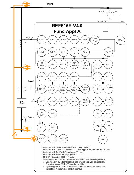
Core function: REF615R is a dedicated intelligent electronic device (IED) for feeder lines, designed specifically for the protection, control, measurement, and monitoring of utility substations and industrial power systems. It is an ABB Relion ®  Part of the 615 series products adopts a compact and withdrawable design.

Unique features

Provide four major replacement conveniences for ANSI and IEC DPU2000R users: the same appearance and size, no need to cut panels or reposition racks; I/O and CT/VT connections similar to wiring greatly reduce drawing modification time; Has considerable protection and control functions, and includes more functions; Close to SCADA compatibility in terms of DNP 3.0 points and Modbus registers.

Other features: six setting groups, pull-out design, optional underground and overhead cable fault detection (CFD), optional high-speed (<1 ms) output, on-site selection of 1A or 5A CT input, advanced user programmable function block, 16 programmable buttons, etc.

Standard configuration

Main applications: feeder protection and control, providing a standard configuration whose relay functions and characteristics are based on the analog inputs ordered for that configuration.

Configuration A: Directional phase and ground overcurrent, voltage and frequency protection, synchronous inspection, control, and power system metering (for one circuit breaker).

Compatible configuration: It can meet and exceed DPU2000R ANSI and IEC configurations, such as standard type, synchronous check type, SEF type, etc.

Protection function

Main protection functions: Provides protection against non directional phase and ground overcurrent, phase step distance, thermal overload, phase imbalance, and phase discontinuity, with sensitive ground fault (SEF), high impedance fault detection (HIZ), directional phase, ground, and neutral overcurrent, as well as phase, ground (residual), positive and negative sequence undervoltage and overvoltage protection.

Other protection functions: Provide three pole multiple automatic reclosing function for overhead distribution feeders of public utilities; Enhanced Arc Flash Detection (AFD), with three light detection channels, is used to detect arc faults in cable compartments of circuit breakers, busbars, and metal enclosed switchgear.

Application scenarios

Provide DPU2000R users with an economical and convenient solution for upgrading and replacing existing ANSI or IEC DPU2000R relays, without the need to change drawings, cut or replace wiring harnesses, cut metal, or add adapter plates.

Suitable for new users looking for the 19 inch rack installation form of ABB Relion 615 series.

Can be applied to various protection, control, and metering scenarios, supporting comprehensive utility and industrial distribution feeder solutions.

Supported ABB solutions

Together with the COM600 grid automation controller, it forms a true IEC 61850 solution for reliable distribution in utility and industrial power systems.

Provide a connection package that includes software and IED specific information, facilitating configuration through PCM600 protection and control of the IED manager, and integrating with COM600 station automation equipment or MicroSCADA Pro network control and management system.

Supports connection with systems such as MicroSCADA Pro and System 800xA.

Control, measurement, and recording functions

Control function: Provide the status and control of a circuit breaker through a set of buttons on the local human-machine interface (LHMI) on the front panel, support remote circuit breaker control, and configure interlocking schemes through the signal matrix tool in PCM600.

Measurement function: Continuously measure phase current and voltage, sequence components and residual current, calculate demand and minimum/maximum demand current, thermal overload of protected objects, phase imbalance values, etc. It can also measure voltage, power and energy, etc.

Recording function: including digital fault recorder (DFR), event sequence recorder (SER), which can store fault records, demand and minimum/maximum demand current data, and has load curve recording function.

Monitoring and diagnostic functions

Circuit breaker status monitoring: including checking the wear and tear of the circuit breaker, the spring charging time of the circuit breaker operating mechanism, the gas pressure in the circuit breaker chamber, etc., monitoring the action time and operation frequency of the circuit breaker.

Trip circuit monitoring: Continuously monitor the availability and operability of the trip circuit, and detect the loss of circuit breaker control voltage.

Self diagnosis: The built-in self diagnostic system continuously monitors the hardware status and software operation of the relay. When a fault or malfunction is detected, it will alert the operator. Permanent relay faults will prevent the protection function of the relay.

Other monitoring functions: fuse fault protection, current circuit monitoring, etc.

Input/Output and Communication

input/output

Analog inputs: including current (CT) and voltage (VT) analog inputs, phase current inputs can be programmed by users to 5A or 1A CT secondary ratings, etc.

Binary Input/Output: The threshold for opening binary input can be programmed by adjusting the parameters of the relay, and all binary input and output contacts can be freely programmed using the signal matrix tool in PCM600 software.

Communication function: Supports multiple communication protocols, including IEC 61850, Modbus ®  And DNP3.0 Level 2+; Provide multiple communication interface options, such as Ethernet interface, serial interface, etc; Support multiple time synchronization methods.

Technical data

Physical characteristics: Width 19.0 inches (482.6 mm), height 5.22 inches (132.6 mm), depth 9.08 inches (230.66 mm), unpacked weight 11.9 pounds (5.4 kg), boxed weight 16.4 pounds (7.44 kg).

Power supply: There are two types of power supplies, with different input voltage ranges and power consumption.

Environmental conditions: working temperature range -25 ° C to+55 ° C, short-term working temperature range -40 ° C to+85 ° C (<16 hours), relative humidity<93% (non condensing), etc.

Electromagnetic compatibility: Passed multiple electromagnetic compatibility tests and meets relevant standards.

Installation and Accessories

Installation methods: rack mounted, semi embedded, and panel mounted. Rack mounted installation requires ordering installation kits.

Accessories: including tools (such as PCM600 V2.5 user tools), cables (such as optical sensor cables for arc protection), installation accessories (such as panel mounting frame/cover kit), spare parts, etc.

ABB EL3020 Model EasyLine Continuous Gas Analyzers

Equipment Overview

Core function: EL3020 is a multi-component continuous gas analyzer that can simultaneously measure up to 5 gas components, suitable for various process and emission monitoring scenarios, and supports flammable gas measurement.

Core features: Equipped with automatic calibration function (including pump and valve control), it can simplify calibration through air or built-in calibration units, without the need to test gas cylinders; Provide customizable analog outputs, digital inputs/outputs, and Modbus interfaces; Adopting a modular design, it is easy to maintain and has self-monitoring function, which can prompt maintenance needs.

Shell design: 19 inch rack mounted shell (3 height units) with a protection level of IP20.

Measurement technology (analyzer)

Uras26 infrared photometer

Measurement object: Infrared active gas components such as CO, NO, SO ₂, etc.

Measurement range: adjustable between 0-500ppm (NO 750ppm), 0-1000ppm, 0-3000ppm, and 0-1Vol. -% to 0-100Vol. -%, with a maximum range ratio of 1:5. Specific ranges can be set according to factory requirements, but the range should not be set within the ignition limit.

Performance indicators: Linear deviation ≤ 1% range; Repeatability ≤ 0.5% range; Zero drift ≤ 1% range/week; Sensitivity drift ≤ 1% measured value/week; Output fluctuation (2 σ) ≤ 0.2% range; Detection limit (4 σ) ≤ 0.4% range.

Influencing factors: Flow rate within the range of 20-100l/h affects within the detection limit; The impact of environmental temperature changes on zero point is ≤ 2% of the range/10 ° C, and on sensitivity (without a thermostat) is ≤ 3% of the measured value/10 ° C. If a thermostat is installed (55 ° C), the impact is ≤ 2% of the measured value/10 ° C. After calibration by a pressure sensor, the impact of pressure changes on sensitivity is ≤ 0.2% of the measured value/1% of the pressure change.

​Magnos206 Oxygen Analyzer

Measurement object: O ₂ in process gas or nitrogen.

Measurement range: minimum range of 0-2Vol. -% O ₂, maximum range of 0-100Vol. -% O ₂, can be set to suppress zero point range (such as 98-100Vol. -% O ₂).

Performance indicators: Linear deviation ≤ 0.5% range; Repeatability ≤ 1% range; Zero drift ≤ 0.1Vol. -% O ₂/week; Sensitivity drift ≤ 0.1Vol. -% O ₂/week or ≤ 1% measured value/week (whichever is smaller); Output fluctuation (2 σ) ≤ 0.5% minimum range; Detection limit (4 σ) ≤ 1% minimum range.

Influencing factors: Flow rate within the range of 30-90l/h affects ≤ 0.1Vol. -% O ₂; Multiple associated gases have different effects on zero point; The impact of ambient temperature on zero point is ≤ 1% range/10 ° C (≤ 2% range/10 ° C when combined with Uras26), and the impact on sensitivity is ≤ 0.2% measured value/10 ° C. After correction, the impact of pressure changes is ≤ 0.01% measured value/1% pressure change or ≤ 0.002Vol. -% O ₂/1% pressure change (whichever is greater).

Caldos27 Thermal Conductivity Analyzer

Measurement object: Binary gas mixtures with different thermal conductivities, such as Ar in O ₂, H ₂ in Ar, CH ₄ in N ₂, etc.

Measurement range: There are different minimum ranges and ranges with zero suppression for different gas combinations, with a maximum range of 0-100Vol. -% or 0Vol. -% to saturation. The range can be freely adjusted within a given range, but should not be set within the ignition limit.

Performance indicators: Linear deviation ≤ 2% range; Repeatability ≤ 1% range; Zero drift ≤ 2%, minimum possible range/week; Sensitivity drift ≤ 0.5% minimum possible range/week; Output fluctuation (2 σ) ≤ 0.5% minimum range; Detection limit (4 σ) ≤ 1% minimum range.

Influencing factors: When the flow rate changes by 10l/h, it affects the range by ≤ 0.5%; The impact of environmental temperature changes is ≤ 1% range/10 ° C; the impact of air pressure changes on the minimum range is ≤ 0.25% range/10hPa, and the larger the range, the smaller the impact.

Electrochemical oxygen sensor

Measurement object: O ₂, and can only be used in combination with Uras26 infrared photometer.

Measurement range: adjustable from 0-5Vol. -% O ₂ to 0-25Vol. -% O ₂, with a minimum range of 0-5Vol. -% O ₂.

Performance indicators: Linear within the range of>1Vol. -% O ₂; Repeatability ≤ 0.5% range; Zero point long-term stability; Sensitivity drift ≤ 1% measurement range/week; Output fluctuation (2 σ) ≤ 0.2% measurement range; Detection limit (4 σ) ≤ 0.4% measurement range.

Influencing factors: Flow rate within the range of 20-100l/h affects ≤ 2% of the measurement range; The impact of changes in ambient temperature within the range of 5-40 ° C is ≤ 0.2Vol. -% O ₂/10 ° C; the impact of changes in air pressure without pressure correction is ≤ 1% of the measured value/1% of the air pressure change, and ≤ 0.2% of the measured value/1% of the air pressure change with correction (to be connected to Uras26 with pressure sensor).

Integrated gas feed (optional)

Version: A module that includes a microfilter and a flow sensor; Another type includes a microfilter, solenoid valve, pump, coarse filter, capillary tube, and flow sensor module.

Performance: The maximum feed rate of the pump is 60l/h (depending on the analyzer type and inlet/outlet pressure), and the flow rate is adjustable; The retention rate of the filter for particles larger than 0.1 μ m is 99.99%.

Restriction: Cannot be used for measuring flammable gases and flammable gas/air or gas/oxygen mixtures.

general data

Shell material: galvanized steel plate (painted on the outer surface), analyzer rear panel made of aluminum and PVC-C, keyboard board made of polyester, with colors of light gray (RAL 7035) and basalt gray (RAL 7012), weighing approximately 7-15kg.

Display and operation: Backlit graphic display screen (240 × 160 pixels), capable of displaying numerical values (with physical units and bar charts), up to 5 measurement values, and flow bar charts, with status display function; Use the 5 keys (cursor cross and OK) to perform menu assistance operations.

Power supply: 100-240V AC (-15%,+10%), 50-60Hz (± 3Hz), maximum power consumption of 187W, equipped with a 3-pin plug and a 2m long connecting cable.

Environmental conditions: working temperature of 5-45 ° C (5-40 ° C when combined with other analyzers), storage and transportation temperature of -25-65 ° C; relative humidity<75%, slight condensation allowed; When installing multiple enclosures in a 19 inch rack, at least one height unit should be separated to ensure sufficient air circulation.

Electrical and gas connections

Electrical connections: including power connections, I/O modules (analog output, digital input/output, RS232/RS485, etc.), Ethernet interfaces, etc., with a maximum terminal capacity of 1mm ² wires.

Gas connection: Different analyzers (Uras26, Magnos206, Caldos27) have different gas inlet and outlet designs, including two versions of hose connection (4mm inner diameter) and pipeline connection (1/8 NPT internal thread). The specific interface functions vary depending on the version and configuration.

authentication

Compliant with the EU Low Voltage Directive (73/23/EC) and EMC Directive (89/336/EC).

Obtained CSA certification in the United States and Canada, compliant with CAN/CSA-C22.2 No.61010-1-04/UL 61010-1:2004 (2nd edition) standards, suitable for general environments.

MOLEX SST-PB3-VME-1 and SST-PB3-VME-2 Hardware

MOLEX SST-PB3-VME-1 and SST-PB3-VME-2 Hardware Reference Guide

​Basic Information

Equipment Overview

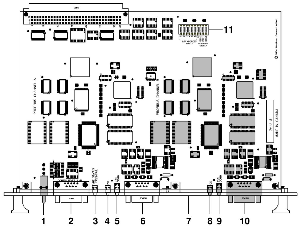
Function: As a VME interface for communication with Profibus networks, SST-PB3-VME-1 includes one Profibus network interface (or channel), while SST-PB3-VME-2 includes two independent interfaces controlled by independent CPUs, each executing downloadable application firmware modules.

Features: Each channel can serve as a DP master and DP slave, sending and receiving FDL (Layer 2) messages, supporting Class 1 and Class 2 master messages, supporting simultaneous operation in all modes mentioned above, supporting standard Profibus baud rates, supporting 16 bit transmission, etc.

Byte order: Adopting Intel style (small end) byte order, for host systems using Motorola (large end) byte order, byte order must be compensated for in the software.

Hardware Description

LED indicator light

SysFail LED: Indicates system status, green indicates default power on status, and red indicates system error.

Watchdog LED: Indicates whether the channel has experienced a watchdog timeout. If it is turned off, it indicates that the status is good and no timeout has occurred; Red indicates that a watchdog timeout has occurred.

Sys LED: Indicates the status of each channel on the card. The meanings of different statuses (off, green, red, amber) should refer to the firmware reference guide.

COMM LED: Indicates the communication status of each channel on the card, with different states (off, green constant, green flashing, red) corresponding to different communication situations.

Profibus connector: Each channel has a standard Profibus DB9 female connector, which introduces recommended connectors and cables.

DIP switch (S1): A 10 bit DIP switch used to set the basic I/O addresses for card configuration, including short I/O addresses, access permissions, interrupts, and other settings.

Hardware installation

System requirements: The controller must comply with the VMEbus specification VME64 (VITA 1.1 1997), have at least 256K windows in the host memory mapping, and be able to generate and receive 16 bit data transfers.

Preventive measures for handling: The card contains components that are sensitive to electrostatic discharge. Proper ESD procedures should be followed during handling to avoid touching the card’s connectors or pins. When not in use, store in an anti-static bag.

Installation steps: Turn off the computer power, ground it, unplug the relevant cables, remove the computer cover, take out the card and set the DIP switch, install the card onto the VME connector, fix the card, reconnect the cables, and cover the computer cover.

Firmware Download: Refer to the relevant section for instructions on downloading firmware to the card.

Connecting to Profibus Network: Introduces the connection, termination, power supply, and grounding details of DB9.

Hardware register details

Host register layout: Each channel has its own set of registers located in the short I/O space, and the base I/O address is set through switches.

Short I/O registers: including control registers, AddrMatch registers, Bank Address registers, WinSize registers, HostIrq ID registers, LedReg registers, Debug registers, HDR registers, VMEReg registers, etc. The bit settings and functional descriptions of each register are introduced.

Troubleshooting

COMM LED is red: The channel is not running or there is an error when the firmware is running. You can check the WdToot bit and refer to the relevant firmware manual. If the problem persists, you can perform general troubleshooting.

Memory Conflict: Check the resource allocation in the operating system. If the operating system does not manage resources, check other hardware requirements to select a conflict free memory window.

General troubleshooting: You can check the website’s technical specifications, common questions, or contact technical support.

Guide code operation

Serial Port: The serial port of the card allows for the transfer of network configuration files and firmware modules to flash memory. This article introduces the methods and commands for connecting to the serial port.

Card Error: Introduces possible errors that may be reported during the startup self-test, including HDR messages and fatal hardware self-test flashing codes.

Technical specifications

Environmental specifications: storage temperature, working temperature, working humidity, etc.

Network specifications: isolation, protocol, data rate, etc.

VME bus specifications: size, resources, etc.

Card size: A size chart of the card is provided.

Loading firmware module

Introduced the basic steps of manually loading firmware modules onto the card, including verifying the existence of the card, checking conflicting RAM, testing card RAM, loading and starting firmware modules, etc.

Precautions

1、 System requirements related

The installation and operation of the card must meet specific system requirements, including the use of a controller that complies with the VMEbus specification VME64 (VITA 1.1 1997), at least 256K windows in the host memory mapping, and the ability to generate and accept 16 bit data transfer (VME D16), supporting VME A24 standard address and VME A16 short I/O address transfer; If interrupt function is required, there must be a physical interrupt, and the interrupt on the 2-channel card will be shared between channels.

2、 Electrostatic protection related

This card contains components that are sensitive to electrostatic discharge, and proper electrostatic protection measures must be followed during operation:

Before touching the card, it is necessary to take electrostatic protection measures, and it is strongly recommended to use a grounded wristband.

It is strictly prohibited to touch any connector or pin of the card, and it should be handled through the edge or bracket of the card.

When the card is not in the computer, it must be stored in a dedicated anti-static bag.

3、 Installation steps related

Before installation, make sure that all computer power is turned off and unplug the power cord, modem (if applicable), and any network cables.

Be careful not to touch the connectors or pins when removing the card from the packaging.

Before installation, the DIP switch should be set to the selected short I/O address according to the instructions in Section 1.4.3.1.

During installation, firmly press the card onto the VME connector and secure it using the provided bracket.

After installation, all previously unplugged items need to be reconnected and the computer cover needs to be closed.

4、 Connecting to Profibus network related

When connecting DB9, it is necessary to follow the prescribed pin connection method and clarify the connection requirements for each pin.

The network terminals and wiring must strictly refer to the provisions of the Profibus document.

Grounding should follow the guidance in the Profibus network documentation.

Eaton XVH300 MICRO PANEL

Basic Information

Document information: Released in November 2014, replacing version M001506. The German version is the original description, and other language versions are translated versions. The copyright belongs to Eaton Automation Co., Ltd. Reproduction and dissemination are prohibited without permission.

Equipment Overview

Name: XVH300 and MH2 are different names for the same product.

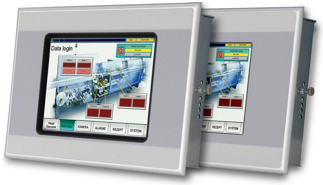
Function: As an HMI device, it is mainly used in mechanical and system manufacturing, specifically for visualization and operation of machines and systems. Other uses require prior consultation with the manufacturer.

Version: Divided into multiple versions based on touch type (resistive, infrared) and interface (no fieldbus, CAN, Profibus, Suconet K, RS232, etc.), such as XVH-330-57BAS, XVH-340-57CAN, etc.

Packaging content: Includes MICRO PANEL host, fixed bracket with threaded pins for installing equipment, installation sealing strip, power connector, etc., and accessories such as handwriting pens can also be ordered.

Safety regulations

Symbol meaning: Different symbols are used according to the degree of danger, such as “DANGER” indicating extreme danger that may result in death or serious injury; Warning “indicates potential danger that may result in death or serious injury.

Personnel requirements: Installation, operation, maintenance, and service personnel must have sufficient qualifications, undergo training, and understand the hazards and risks related to the equipment.

Prohibited use: The use of this device for safety purposes (related to personnel and machine protection) is prohibited.

Equipment related hazards and prevention

There is a risk of explosion, and specific requirements must be followed when operating in potentially explosive environments, such as avoiding dangerous impacts, disconnecting plug connections after power failure, etc.

There are live parts inside the equipment. It is forbidden to open the equipment to prevent electric shock.

The protective grounding system between different devices may generate large balanced currents, and equipotential bonding conductors need to be installed if necessary.

Static discharge may damage electronic components, so it is necessary to release body static electricity before coming into contact with the equipment.

Resistive touch surfaces are sensitive, avoid touching with sharp objects, and ensure gloves are clean when operating.

Operation and indication components

Front: There is a touch sensor (detecting the triggering of operating elements on the display screen) and a display screen (displaying operating and indicating elements).

Service side: There are operating components such as CF card slot cover, CF slot, eject button, control button, as well as indicator components such as CF ACT, CAN ACT/PROFIBUS ACT. Different indicator lights have different meanings, such as CF ACT light on indicating that the CF card is being accessed.

On the connector side of the SKS device, there are indicator lights such as “COM PORT ERROR” and “COM PORT ACT”, as well as a “LINE TERM. COM PORT” switch, which are used to indicate data transmission errors, data transmission activity, and control the terminal resistance of the RS485 interface.

Installation

Installation location requirements: It needs to be installed in an approved location, and the power supply must meet the requirements. Considering the engineering acceptance conditions of UL certification, the installation location should avoid direct sunlight, ensure that the operating components and cable connections on the service side of the equipment are accessible, meet environmental conditions and ventilation requirements, and the installation surface must meet specific thickness, flatness, and roughness requirements.

Interface: Different versions of devices have different interfaces, including Ethernet, CAN, Profibus, RS232, RS485, USB device interfaces, power interfaces, etc. Each interface has corresponding wiring requirements and specifications.

Installation steps: Check for equipment transportation damage, prepare installation cuts in control cabinets and other locations, install sealing strips, place the equipment into the installation cut from the front, fix it with fixed brackets, etc. Pay attention to relevant safety regulations during installation.

Operation

Safety regulations: Before operation, it is necessary to read the safety regulations section and pay attention to protecting the resistive touch surface to avoid turning on the device when condensation occurs due to climate change.

Start the device: Insert a CF card with an operating system, turn on the power, and the device will start. After initial debugging, adjust the system settings and install the required applications.

Turn off the device: Disconnect the power of the device. Before turning off, make sure that no software is writing to the CF card to avoid frequent device switching to extend the backlight life.

Maintenance and Service

Safety regulations: Before maintenance, it is necessary to read the safety regulations chapter.

Maintenance work: Resistive touch devices are basically maintenance free, and can be cleaned or recalibrated if necessary; Infrared touch devices require regular cleaning of the infrared frame and do not require recalibration.

Battery: The built-in battery is non replaceable and has a certain lifespan.

Maintenance: The equipment can only be opened by the manufacturer or authorized maintenance center. Maintenance requires contacting the local supplier or Eaton technical support. Transport equipment must be in its original packaging.

Troubleshooting: Listed the reasons and solutions for common faults such as device failure to start, error messages during startup, screen dimming, and unresponsive touch.

Storage, transportation, and disposal

Storage: Must meet environmental conditions requirements.

Transportation: During transportation, it is necessary to prevent equipment damage and meet environmental conditions. After arrival, inspect the equipment for transportation damage.

Disposal: The equipment contains explosive and toxic materials such as lithium batteries and cold cathode tubes, which need to be properly disposed of or returned to the manufacturer in accordance with national regulations. The materials used for the equipment and packaging should be explained.

Eaton XV-303/XV-313 multi touch display

Basic Information

Document information: Released in March 2025, version 01.1, copyright belongs to Eaton Corporation. Reproduction, dissemination, etc. are not allowed without permission.

Equipment Overview

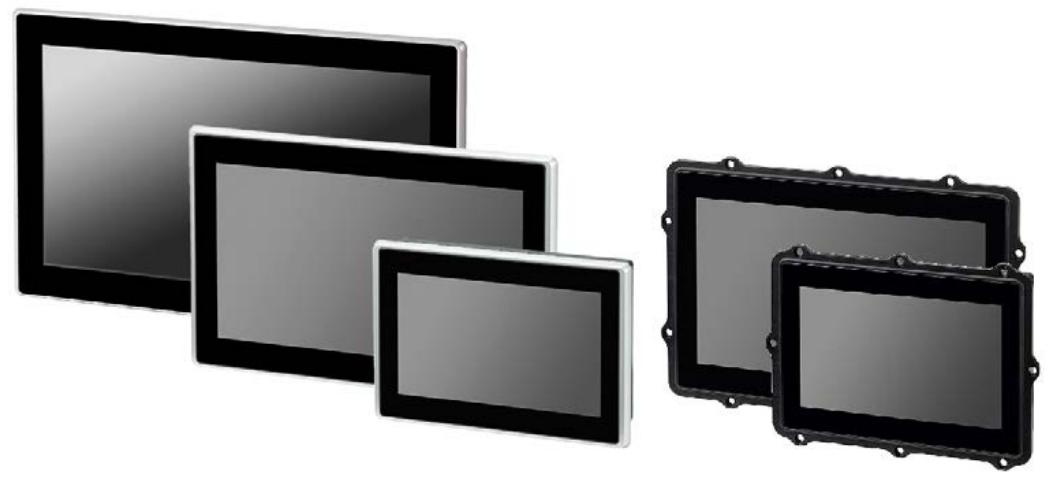
Function: It can be used as an operation and monitoring device, or as an operation and control device with PLC function. It adopts industrial high-resolution capacitive multi touch technology, has an intuitive gesture based user interface, and a powerful graphics processing unit.

Model difference: XV-303 is a front mounted type, while XV-313 is a rear (panel) mounted type.

Display size: There are three widescreen sizes: 7.0 inches, 10.1 inches, and 15.6 inches, with resolutions of 1024×600 pixels and 1366×768 pixels, respectively.

Processor and Memory: Equipped with an 800MHz ARM Cortex-A9 processor, 1GB of internal memory and 128kB of non-volatile data storage, the memory can be expanded through an SD card.

Operating system: Linux operating system is used.

Safety regulations

Personnel qualifications: Installation, operation, maintenance, and repair personnel must possess corresponding qualifications, undergo appropriate training, and understand the hazards and risks related to the equipment.

Precautions before installation: Installation must be carried out by a qualified electrician. Before installation, disconnect the equipment power supply to prevent re triggering, verify isolation from the power supply, grounding and short circuit, cover adjacent live parts, etc.

Equipment specific hazards and prevention

There is a risk of explosion, and it can only be used in non hazardous areas and hazardous areas defined by the ATEX directive in Zone 22 to avoid dangerous impacts.

Improper handling of lithium batteries may cause explosions, and professional equipment disposal is required.

Static discharge may damage components, and static electricity should be released before contacting the equipment.

Non galactic isolated interfaces may damage equipment due to potential differences, and power must be disconnected before connecting and disconnecting connectors.

Installation

Installation location requirements

The environmental temperature, air pressure, humidity, etc. must comply with regulations and avoid direct sunlight and heat sources.

The installation location should ensure that the device controls and connectors are accessible, taking into account the space required for removing the SD card.

There are specific requirements for the installation angle and panel thickness of different models.

Installation steps

Unpack and inspect the equipment for any transportation damage, and verify the contents of the packaging.

The front installation type and the rear installation type have different fixing and sealing methods and steps.

Preparation for operation: Connect the grounding function and pay attention to the specifications of the grounding wire; Connect the power supply by an electrician, paying attention to voltage polarity and requirements.

Debugging

Initial debugging: Configure system settings and install required software packages.

Operation: After connecting to the power supply, the device will start without the need for a separate switch. Lowering the brightness can extend the lifespan of the monitor backlight. In case of any malfunctions, please refer to the troubleshooting section.

External connection

Interface types: including SD card slots, USB host and device interfaces, Ethernet interfaces, RS-232, RS-485, CAN1 interfaces, etc. Different interfaces have corresponding specifications and connection requirements.

Connection precautions: Avoid stray currents, use appropriate cables and correctly assemble terminations, follow relevant standards and instructions.

Troubleshooting

Listed the reasons and solutions for common malfunctions such as device failure to start, monitor dimming, unresponsive or incorrectly responsive touch technology.

Maintenance

Cleaning and maintenance: The equipment is basically maintenance free. When the touch technology gets dirty, it can be cleaned with a clean, soft, and damp cloth, and recalibrated if necessary.

Maintenance: Maintenance requires contacting the supplier or Eaton technical support, and the equipment can only be opened by the manufacturer or authorized center.

Storage, transportation, and disposal: Storage and transportation must comply with environmental conditions, avoid UV light and condensation water, and equipment scrapping must be professionally disposed of, following local recycling regulations.

ABB Panel 800 Version 6 Operator Panel

Product overview

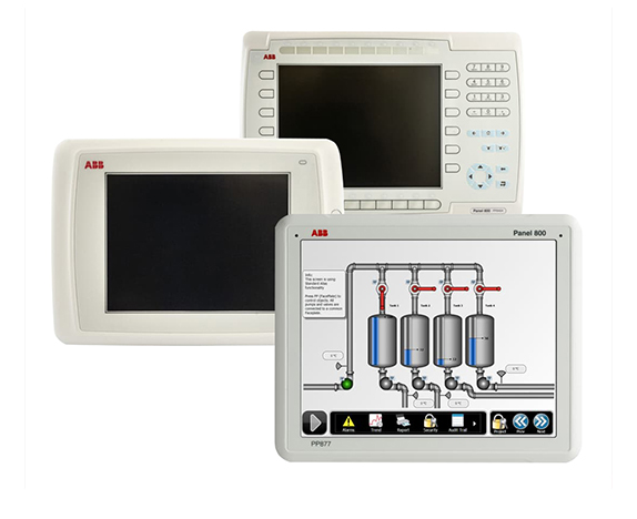
ABB PP877 3BSE069272R2 is a 10.4-inch touch standard panel in the ABB Panel 800 Version 6 series, mainly used in industrial automation and control systems, providing operators with a convenient human-machine interaction interface.

The ABB Panel 800 Version 6 series operator panel is designed to be user-friendly, intuitive to operate, and ergonomic, combining compact and space saving dimensions with rich advanced features, aiming to simplify process automation operations. The panel controls the process and equipment through the function keys next to the screen or by touching the LCD display screen, making it suitable for various industrial automation scenarios.

Basic information

Belonging to the Panel 800 Version 6 series, this series is designed to meet the needs of human-machine communication, with rich functions and easy operation.

Product type: Touch standard panel, realizing monitoring and control of industrial processes through touch operation.

Origin and brand: The origin is Sweden, the brand is ABB, and it has a high reputation in the fields of electrical and automation.

Performance parameter 

Display performance: Equipped with a TFT-LCD display screen with a resolution of 640 × 480 (4:3), LED backlight, brightness of up to 450cd/m ², viewing angle of 160 °/140 °, clear display, wide viewing angle, ensuring image quality even when viewed from different angles. Equipped with dimming function, the screen brightness can be adjusted according to the ambient light.

Processing capability: Equipped with ARM9 (400MHz) processor, it has 128MB (DDR2) main memory and 80MB application memory, which can meet the basic needs of industrial application program operation and data processing.

Storage Expansion: Equipped with one SD card slot (supporting SDHC), convenient for storing project files, data records, etc.

Communication interface: Integrate one 10/100Base-T Ethernet interface (shielded RJ45) for network communication with other devices; It also has 2 combination ports, supporting 2 × RS232 and 2 × RS422/485 serial communication, making it easy to connect various serial devices.

Mechanical specifications: The external dimensions are 280 × 228 × 51mm, and the installation opening size is 262 × 209mm. It adopts panel installation and VESA 75 × 75 installation methods, making installation convenient. Net weight of 1.5kg, made of powder coated aluminum, with a sturdy and lightweight structure.

Electrical parameters: The power supply is+24VDC (18-32VDC), with a power consumption of 9.6W, which can adapt to a certain range of voltage fluctuations and ensure stable operation in different power supply environments.

Environmental adaptability: The protection level is IP66 (front)/IP20 (back), which can effectively prevent dust and water from entering and is suitable for various industrial environments. The working temperature range is -10 ° C to+60 ° C, the storage temperature is -20 ° C to+70 ° C, and the relative humidity is 5-85% (non condensing), which can adapt to a certain degree of temperature and humidity changes.

Functional Features

Interface and operation: The resistive touch screen supports 1 million touch operations, combined with an intuitive user interface, making it easy for operators to monitor and control industrial processes. Built in multiple functions, such as text display and control, dynamic indication, time channel, alarm and formula processing, etc., make it convenient for users to manage industrial processes.

Communication capability: Supports multiple communication protocols and can be used as a master or slave to communicate with other devices, such as ABB COMLI protocol, Modbus protocol, etc. It can exchange data with devices of different brands and types.

Convenient configuration: The Panel Builder configuration tool can be used to configure on a PC, supporting multiple languages, and the operating interface is similar to the Microsoft Windows environment, making it easy for users to get started.

Application areas: Widely used in multiple industrial fields such as power systems, manufacturing, water treatment, facility management, HVAC systems, machine control, power generation, and distribution, to achieve real-time monitoring and precise control of industrial processes

Main models and classifications

(1) Standard panel

PP871, 3BSE069270R2, 4.3 “, 480 × 272 (16:9), TFT-LCD 64k color, LED backlight, brightness 350 cd/m ², viewing angle 140 °/115 °, resistive touch (1 million touch operations)

PP874, 3BSE069271R2, 7 “, 800 × 480 (16:9), TFT-LCD 64k color, LED backlight, brightness 350 cd/m ², viewing angle 140 °/130 °, resistive touch (1 million touch operations)

PP877, 3BSE069272R2, 10.4 “, 640 × 480 (4:3), TFT-LCD 64k color, LED backlight, brightness 450 cd/m ², viewing angle 160 °/140 °, resistive touch (1 million touch operations)

PP874K, 3BSE069273R1, 7 “, 840 × 480 (16:9), TFT-LCD 64k color, LED backlight, brightness 350 cd/m ², viewing angle 140 °/130 °, buttons (1 million button operations)

PP877K, 3BSE069274R1, 10.4 “640 × 480 (4:3), TFT-LCD 64k color, LED backlight, brightness 450 cd/m ², viewing angle 160 °/140 °, buttons (1 million button operations)

(2) High performance panel

PP882, 3BSE069275R1, 12.1 “, 1280 × 800 (16:10), TFT-LCD 262k color, LED backlight, brightness 400 cd/m ², viewing angle 176 °/176 °, resistive touch (1 million touch operations)

PP885, 3BSE069276R1, 15.4 “, 1280 × 800 (16:10), TFT-LCD 262k color, LED backlight, brightness 450 cd/m ², viewing angle 160 °/140 °, resistive touch (1 million touch operations)

(3) Other specific model panels

Including PP874M, PP885M, PP885H, etc. Taking PP885H as an example, it has a display size of 15.4 inches, a resolution of 1280 × 800 (16:10), TFT color LCD, 16.7 million colors, LED backlight, brightness of 1000 cd/m ², and resistive touch (5 million touch operations).

(4) Durable panel

PP880R, 3BSE069295R1, 7 “, 800 × 480 (16:9), TFT color LCD, 16.7 million colors, LED backlight, brightness 500 cd/m ², viewing angle 140 °/120 °, resistive touch (1 million touch operations)

ABB触摸屏PP877K 10.4英寸新型PP877 3BSE069272R2 - 雄霸工业

ABB 1SVR011718R2500 Analog Signal Converter

Product overview

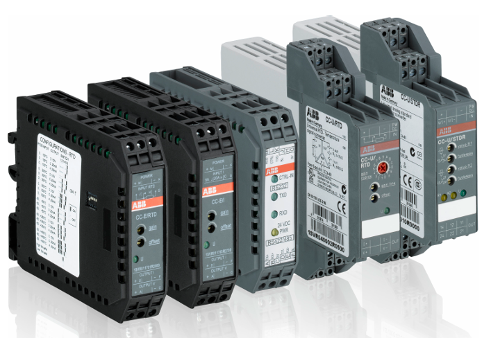
The ABB 1SVR011718R2500 analog signal converter belongs to the CC-E/STD series and is widely used in industrial automation, building automation, and process control fields for the processing and conversion of analog signals.

ABB analog signal converters include two series, CC-E and CC-U, which are mainly used for the conversion, measurement, amplification, filtering, and isolation of analog signals in industrial processes. They solve compatibility, interference, grounding loops, and other problems in signal transmission, ensuring accurate reception and processing of signals by control systems.

CC-E series

(1) Product features and advantages

Contains both general configuration devices and single function devices, with adjustment and operation components located on the front.

Equipped with electrical three-way isolation to ensure safe operation, with clear and distinct identification of wiring terminals.

Single function devices do not require adjustment or balancing; General equipment can configure input and output ranges through the DIP switch on the side, and the potentiometer on the front can adjust gain and offset by ± 5%.

(2) Main types and functions

Standard signal converter (CC-E/STD, etc.): processes the conversion of standard signals (0-5V, 0-10V, 0-20mA, 4-20mA, etc.) to achieve various conversions such as voltage voltage, voltage current, current voltage, and current current.

Thermal Resistance Converter (CC-E/RTD): It converts the temperature signal of PT100 thermal resistance, supports 2-wire or 3-wire connection, and outputs multiple standard signals.

Thermocouple Converter (CC-E/TC): processes J-type and K-type thermocouple signals, with cold junction compensation function, and outputs standard signals.

Current measurement converter (CC-E/I, etc.): measures AC/DC current signals from 0-5A and 0-20A and converts them into standard signals; CC-E IAC/ILPO does not require an auxiliary power supply and is used for sinusoidal current measurement.

Circuit power supply current isolator (CC-E I/I-1/2): realizes electrical isolation of current signals, with an internal voltage drop of ≤ 2.5V, and has 1 or 2 independent channels.

(3) Technical parameters

Power supply: 24V DC or 110-240V AC, typical power consumption is 1.5W/1.5VA.

Working temperature: 0…+60 ° C, storage temperature: -20…+80 ° C.

Accuracy: ± 0.5% full scale (some types), response time varies depending on the type, such as standard signal conversion of about 200 µ s and temperature signal conversion of about 10ms.

Protection level IP20, compliant with multiple standards and directives (EN 50178, Low Voltage Directive, etc.).

CC-U series

(1) Product features and advantages

One device can provide 8 different standard signal outputs, and both input and output sides can be configured universally. Some models come with 2 threshold relay outputs.

The regulating and operating components are located on the front, with electrical three-way isolation, using plug-in terminal blocks, and clearly labeled.

All devices can be configured with the required input and output range through the DIP switch on the side. The wide input range of the gain and offset stages makes signal conversion more flexible, and there are DC or AC (50/60Hz) power supply versions available.

(2) Main types and functions

Universal Signal Converter (CC-U/STD): Supports over 120 configurations and can configure the output response when the input signal is interrupted. The output signal has short-circuit protection.

Thermal resistance converter (CC-U/RTD): suitable for PT10, PT100, PT1000 and other thermal resistors, supporting 2-wire or 3-wire connections.

Thermocouple Converter (CC-U/TC): Processing signals from various types of thermocouples (K, J, T, S, etc.), capable of temperature difference measurement, with optional cold end compensation.

Voltage measurement converter (CC-U/V): measures true RMS (TRMS) from 0-600V, suitable for voltage signals of various waveforms.

Signal converters with relay outputs (CC-U/SDDR, CC-U/TCR): CC-U/SDDR processes standard signals, CC-U/TCR processes thermocouple signals, both with two threshold relay outputs, and the threshold and hysteresis can be independently adjusted.

Current measurement converter (CC-U/I): measures true RMS current signals of 0-1A and 0-5A, suitable for various waveforms.

Technical Parameter

Physical parameters

Size: 75mm high x 22.5mm wide x 107mm deep, compact in size and structure, easy to install in various control cabinets, saving space.

Weight: Approximately 99.875g (0.084kg or 0.22lbs), lightweight, easy to transport and install.

Protection level: IP20, capable of preventing solid foreign objects with a diameter greater than 12.5mm from entering, and can be used in general industrial environments.

Installation method: Standard DIN rail installation, convenient and fast, easy to install and layout in industrial control cabinets.

Environmental parameters

Working temperature range: -20 ° C to+60 ° C (some sources mention up to -40 ° C to+85 ° C or 0…+60 ° C), can adapt to industrial environments with certain temperature changes, but exceeding this range may affect equipment performance and lifespan.

Storage temperature range: -20…+80 ° C. Storing devices within this temperature range ensures stable performance and prevents damage due to temperature issues.

Relative humidity: 5% -95% RH (no condensation), with certain requirements for the humidity of the usage environment. Avoid using in high humidity and easily condensing environments to prevent affecting the electrical performance and service life of the equipment.

Other

Isolation design: It has 3 electrical isolation channels, which can effectively isolate input and output signals, prevent interference, and improve the safety and stability of the system.

Standard compliance: Compliant with RoHS, UL 61010-1, UL 61010-2-201, CE and other standards to ensure product quality and safety.

ABB BC810K02 CEX Bus Interconnection Unit Kit

Product overview

BC810K02 is a CEX Bus interconnect unit kit launched by ABB, mainly composed of BC810 interconnect unit, TP857 base board, TK851 interconnect cable, and TB850 CEX Bus terminator, used to enhance the availability of CEX Bus. Its core function is to divide CEX Bus into independent sections, support redundant communication interface units, enhance the stability of the system under redundant communication interface configuration, and be suitable for industrial automation systems that require high availability.

Composite and structure

Core components: The kit includes 2 BC810 interconnect units, 2 60mm wide TP857 base plates, 1 1.0-meter-long TK851 interconnect cable, and 2 TB850 CEX Bus terminators.

BC810 unit structure: consisting of a base board (TP857) and a power/logic board.

Base board: Integrated with CEX Bus connector and external power interface, grounded to DIN rail through shell metal components, and carrying voting diodes and fuses for external power supply.

Power/Logic Board: Includes+3.3V converter, logic circuit, CEX Bus interconnect driver, and interconnect cable connectors.

Compatibility and system characteristics

Compatible with CPU modules: Can be used in conjunction with CPU modules such as PM857, PM861A, PM862, PM863, PM864A, PM865, PM866, PM866A, PM867, and PM891.

Redundancy support: Supports redundant system configuration, enabling online replacement of CPU base boards without interfering with CEX communication in fully redundant systems with dual BC810 interconnection and equipped with primary/backup CPU pairs; But when replacing BC810, the communication of the connected CEX section will be suspended.

CEX Bus function: Used to expand onboard communication ports to connect communication interface units, supports redundant communication interfaces, and improves bus availability by partitioning.

Key features and advantages

Support redundant communication interface units to enhance system communication reliability.

Allow online CPU replacement to ensure continuous system operation.

Powered by an external power source, stable and reliable.

Support hot swapping for easy maintenance and component replacement.

​Technical Parameter

Product Code 3BSE031155R1 (BC810K02)

Redundancy capability: support

High integrity: support

Power consumption: typical 50mA at+24V voltage, maximum 70mA; typical power consumption 1.2W

Power input: 24V DC (allowable range 19.2-30V DC)

Working temperature:+5 to+55 ° C (+41 to+131 ° F)

Storage temperature: -40 to+70 ° C (-40 to+158 ° F)

Relative humidity: 5% -95% (without condensation)

Protection level: IP20 (compliant with EN60529, IEC 529)

Certification of CE mark; Electrical safety complies with UL 61010-1 and UL 61010-2-201; Certification for hazardous locations: cULus Class 1, Zone 2, etc; Ship certification ABS, BV, DNV-GL, LR; Compliant with RoHS (EN 50581:2012) and WEEE (Directive/2012/19/EU) standards

Dimensions: Width 59mm (2.9 inches), Height 185mm (7.3 inches), Depth 127.5mm (5.0 inches)

Weight (including base): 1.5kg (3.31 pounds)

Working principle

Hardware collaboration principle: It consists of a base board (TP857) and a power/logic board. The base board is responsible for connecting the CEX Bus and external power supply, and is grounded through the metal components of the housing to ensure electrical safety. It also carries the voting diode and fuse of the external power supply, and performs preliminary treatment on the power supply. The power/logic board converts external power to+3.3V for internal use, while its logic circuit and CEX Bus interconnect driver are responsible for data processing and transmission, and interacts with other devices through interconnect cable connectors.

System communication principle: In industrial automation systems, CEX Bus is used to expand onboard communication ports. BC810K02 reduces communication interference between different devices and improves communication efficiency and reliability by dividing CEX Bus into separate sections. In a fully redundant system, two interconnected BC810s work with primary/backup CPUs, supporting online replacement of CPU base boards without interfering with CEX traffic and maintaining stable system communication; But when replacing BC810 itself, the communication of the connected CEX section will temporarily stop. In addition, it supports redundant communication interface units. When a communication interface fails, the redundant interface can take over the work in a timely manner, ensuring uninterrupted data transmission and improving the availability of the entire system.

ABB RELION ®  615 series REU615 voltage protection

Product overview

REU615 is ABB RELION ®  There are two standard configurations (A and B) for voltage protection and control relays in the 615 series. Configuration A is applicable to voltage and frequency based protection schemes in power systems and distribution systems, including networks with distributed generation; Configuration B is specifically designed for automatic voltage regulation of power transformers equipped with on load tap changers. Both configurations have additional functions such as circuit breaker control, measurement, and monitoring, and adopt a compact withdrawable unit design, fully utilizing the potential of IEC 61850 standard in communication and interoperability between substation automation equipment.

Core functions and features

Protection function

Voltage protection: including three-phase overvoltage protection (3U>), three-phase undervoltage protection (3U<), residual overvoltage protection (Uo>), positive sequence undervoltage protection (U1<), negative sequence overvoltage protection (U2>), etc., which can cope with different voltage abnormal situations.

Frequency protection: It has over/under frequency (f>/f<) and frequency change rate (df/dt) protection functions to prevent damage to network components caused by abnormal system frequency.

Overcurrent protection: Configuration B includes three-phase non directional overcurrent protection (low, high, instantaneous stages) for detecting overcurrent and short circuit faults.

Thermal overload protection: Configure B’s three-phase thermal overload protection (with two time constants) to monitor the thermal stress of the transformer winding and prevent premature aging of the winding insulation.

Other protections include arc protection (optional configuration A), multi-purpose protection, and other functions.

Control function: Supports circuit breaker control, isolation switch control, grounding switch control, on load tap changer control, etc., which can achieve effective control and interlocking of primary equipment.

Measurement function: It can measure various electrical parameters such as three-phase current, voltage, residual current, residual voltage, sequence current, sequence voltage, power, energy, frequency, etc. It can also perform RTD/mA measurement (configuration B is optional).

Data recording and event recording

Disturbance recorder: capable of recording analog and digital channel data, with sampling frequency varying depending on the rated frequency, adjustable recording length, and diverse triggering methods.

Fault record: Record fault related data for easy fault analysis and diagnosis.

Load curve recording: The load history of the corresponding feeder can be observed.

Communication function: Supports multiple communication protocols, including IEC 61850 (supporting Edition 2), IEC 61850-9-2 LE (process bus) IEC 60870-5-103、Modbus ®、 DNP3, etc., have Ethernet redundancy (HSR, PRP), self-healing Ethernet ring and other functions, which can achieve secure communication.

Human Computer Interaction: Equipped with Local HMI (LHMI) and Web HMI (WHMI), LHMI includes a display screen, LED indicator lights, and keyboard for easy local settings, monitoring, and control; WHMI can securely access relays through a web browser.

Authorization and Audit Tracking: Four predefined user categories (VIEWER, OPEROTOR, ENGINEER, and ADMINIST) are defined, each with different permissions; Equipped with audit tracking function to record critical systems and security related events.

Standard configuration

Configuration A

Application scenario: It is applicable to voltage protection and synchronization check in the medium voltage network. It can handle the fault caused by abnormal voltage in the power system, and can handle the synchronization and power on check of two galvanically interconnected networks.

Main functions: including voltage protection (overvoltage, undervoltage, residual voltage, sequence voltage, etc.), frequency protection, load shedding and recovery, arc protection (optional), synchronous inspection, as well as control functions such as circuit breakers, isolation switches, grounding switches, etc.

Configuration B

Application scenario: Used for automatic voltage regulation of power transformers equipped with on load tap changers, including three-phase non directional overcurrent protection, three-phase undervoltage and overvoltage protection, etc.

Main functions: In addition to voltage protection, overcurrent protection, thermal overload protection, etc., it also has functions such as on load tap changer control and voltage regulation, tap changer position indication, etc. The optional RTD/mA input module is used for temperature measurement, etc.

Technical parameters and requirements

1、 Requirements for measuring transformers

(1) Current Transformer (CT)

Requirements for CT for overcurrent protection

Accuracy level and accuracy limit coefficient: The accuracy level of current transformers used for protection is usually represented by “P” (meaning protection), followed by the number indicating the maximum allowable composite error at the rated accuracy limit current. For example, 5P10 represents an accuracy level of 5P and an accuracy limit coefficient of 10. Both 5P and 10P levels are suitable for non directional overcurrent protection, with 5P level having higher accuracy.

Actual accuracy limit coefficient calculation: The actual accuracy limit coefficient (F a) is related to the rated accuracy limit coefficient (F n), CT rated load (S n), CT internal secondary load (S in), and actual external load (S). The calculation formula is:

F a ≈ F n × ∣ S n+S ∣∣ S in+S n ∣ CT selection principle: For non directional overcurrent protection, it is recommended to choose a CT with an actual accuracy limit factor of at least 20. The rated primary current (I 1n) of the CT should meet the requirement of I 1n>I kmax/100 (I kmax is the maximum fault current) to avoid exceeding the thermal and dynamic intensity of the input current measurement of the protective relay.

Suggestion for starting current setting: If I kmin is the lowest current that should be activated during the highest set overcurrent stage, the starting current should be set to:

The current starting value, with a coefficient of 0.7, takes into account protection relay error, CT error, and short-circuit calculation deviation.

2、 Input parameters

(1) Incentive input

Phase current (configuration B)

Terminals: X120:7-8 (IL1), X120:9-10 (IL2), X120:11-12 (IL3)

Can be used for single-phase or two-phase applications, where some excitation inputs can be left vacant, but at least X120:7-8 needs to be connected

Residual current (configuration B)

Terminal: X120:13-14 (Io)

Phase voltage (configuration B)

Terminals: X120:1-2 (U1), X120:3-4 (U2), X120:5-6 (U3)

Phase voltage (configuration A)

Terminals: X130:11-12 (U1), X130:13-14 (U2), X130:15-16 (U3)

SECRSYN1 reference voltage (configuration A)

Terminal: X130:9-10 (U12B)

Residual voltage (configuration A)

Terminal: X130:17-18 (Uo)

(2) RTD/mA input (configuration B optional)

Terminals and corresponding functions:

X130:1-2:mA1(AI1)

X130:3-4:mA2(AI2)

X130:5-6:RTD1(AI3)

X130:7-8:RTD2(AI4)

X130:9-10:RTD3(AI5)

X130:11: RTD channels 1-3 common ground

X130:12: RTD channels 4-6 common ground

X130:13-14:RTD4(AI6)

X130:15-16:RTD5(AI7)

X130:17-18:RTD6(AI8)

Search for products

Back to Top
Product has been added to your cart